Corrosion has become an important issue in refineries as incoming crude conditions change and plants age. By following best practices in design, chemical treatment and corrosion monitoring, refineries can mitigate corrosion risk. This article will discuss how to do this in hydroprocessing units.
The growing demand for transportation fuels and the shift toward diesel makes hydroprocessing increasingly important. Hydroprocessing units help the refining industry meet global demand for cleaner fuels, even with an increasingly challenging feedstock of heavier crude slates with higher contaminant levels. Hydroprocessing units are key components of a competitive refinery configuration to shift available feedstocks into desirable and marketable product distributions.
In these units, hydrocarbon intermediates and products are reacted with hydrogen in the presence of a catalyst to produce high-value clean and lighter products. Feedstock and operating conditions such as temperature, partial hydrogen and absolute system pressure depend on the final application. Feedstocks can include every refinery intermediate and product, as well as straight-run and cracked feedstocks.
Higher system pressures and the appropriate catalyst generally enable a deeper chemical conversion and cracking of carbon-carbon bonds, while milder hydroprocessing removes contaminants.
Process designTwo of the major hydroprocessing applications are hydrotreating and hydrocracking.
Hydrotreating removes undesired feedstock components and reduces contaminants, such as sulfur and nitrogen, to avoid catalyst poisoning and mitigate downstream corrosion. Hydrocarbon components such as aromatics are removed to enhance product qualities. Blending pool properties like cetane number, density and smoke point can be improved with customised catalysts and process configurations. Dewaxing capabilities of certain catalysts improve cold-flow properties for blending components in the middle distillate pool.
Hydrocrackers break down carbon-carbon bonds of a heavy feed to produce higher value products, such as gasoline, kerosene and diesel components. A hydrocracker uses significant
While solutions exist to combat corrosion in refineries, sensors are required to measure effectiveness. Christiane Lederer, Emerson Automation Solutions, USA, explains why.
GETTING THE MEASURE OF CORROSION
GETTING THE MEASURE OF CORROSION
Reprinted from November 2017 HYDROCARBON ENGINEERING
quantities of hydrogen, which is boosted to 150 bar pressure by large gas compressors. Sulfur and nitrogen in the first stage hydrocracker are removed by adding hydrogen to the feed, heating this mixture in a furnace, and passing the feed into high pressure reactor vessels over a catalyst.
In both hydrotreaters and hydrocrackers, the feed is passed to exchangers, heated by the reactor effluent and a fired heater, and fed to the reactors at 700 – 750°F (370 – 400°C). Pressures in hydrotreaters normally range from 350 to 500 psia (2415 – 3450 kPa); the pressure in the hydrocracker ranges from -1500 to 2000 psia (10 340 – 13 790 kPa).
Depending on the process application, the feedstock molecules are broken down and cracked. The released sulfur
reacts to form hydrogen sulfide (H2S) and mercaptans together with traces of ammonia and hydrogen cyanides. The reactor effluent of hydrotreaters is subsequently cooled through a series of exchangers before being sent to a high pressure separator vessel to remove the hydrogen sulfide downstream from the separated gas.
The hydrogen sulfide-free gas is recycled back to the feed. The liquid phase from the high pressure separator is passed through a letdown valve to a low pressure separator.
Liquids from the low pressure separator are then fed to a fractionator.
In a hydrocracker, the effluent of the first stage is also cooled and sent to a high pressure separator. In many of the hydrocracking processes, the liquid from the high pressure separator is fed to a heater and to a second stage reactor. The effluent from the second stage usually undergoes exchange cooling, high and low pressure separation, and fractionation. The bottom product of the fractionator is often recycled to the feed of the second stage hydrocracker.
Particularly in the first stage, hydrocrackers are treated the same as hydrotreaters for materials selection. A design pressure of 650 psia (4480 kPa) differentiates low pressure hydrotreating unit materials from high pressure units for hydrocracking.1
Design considerations and guidelinesService of steels in high temperatures over 450°F (232°C) and under high pressure hydrogen require material selection and design standards to mitigate corrosion and cracking. Mitigating high temperature and high pressure hydrogen attack by choosing appropriate reactor materials for the given process application is addressed by API RP 491. The Nelson curves for different materials define the acceptable operating window below the curves, with the hydrogen partial pressure and operating temperature as diagram axes. The curves are periodically revised based on industry experience.
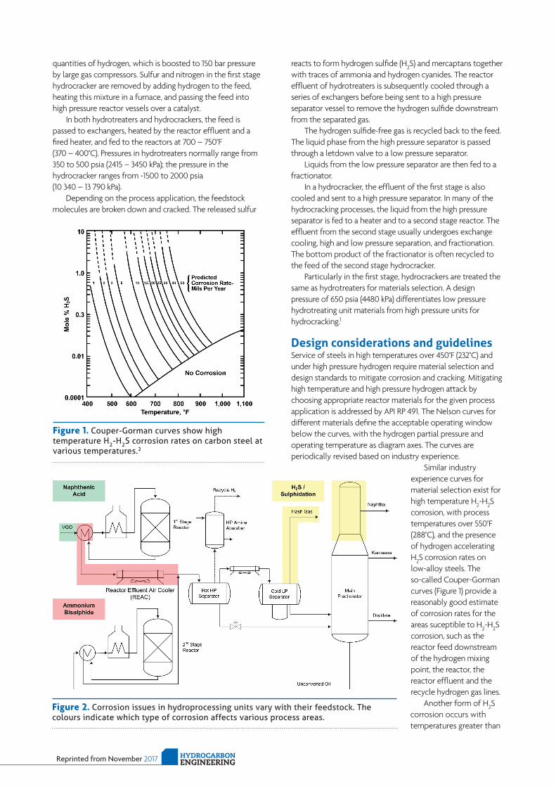
Similar industry experience curves for material selection exist for high temperature H2-H2S corrosion, with process temperatures over 550°F (288°C), and the presence of hydrogen accelerating H2S corrosion rates on low-alloy steels. The so-called Couper-Gorman curves (Figure 1) provide a reasonably good estimate of corrosion rates for the areas suceptible to H2-H2S corrosion, such as the reactor feed downstream of the hydrogen mixing point, the reactor, the reactor effluent and the recycle hydrogen gas lines.
Another form of H2S corrosion occurs with temperatures greater than
Figure 1. Couper-Gorman curves show high temperature H2-H2S corrosion rates on carbon steel at various temperatures.2
Figure 2. Corrosion issues in hydroprocessing units vary with their feedstock. The colours indicate which type of corrosion affects various process areas.

Reprinted from November 2017HYDROCARBON ENGINEERING
500°F (260°C) and where little to no hydrogen is present. Susceptible hydroprocessing unit sections are the feed areas upstream of the hydrogen mixing point and fractionators after the hydrogen gases have been separated (Figure 2). McConomy curves are most commonly used when designing these areas.
Other design and process procedure considerations include the mitigation of chloride stress corrosion cracking, hydrogen induced cracking and stress-oriented hydrogen induced cracking.
Careful design considerations are the foundation for the safe and efficient operation of a hydroprocessing unit. Loss of containment with hydrocarbon processing units at elevated operating temperatures have potentially catastrophic consequences, especially with units operating at such high pressures and with an abundance of hydrogen.
Changing crude slates and ageing assets create novel corrosion challenges that economically threaten refiners due to unplanned shutdowns, calling for an active approach to asset integrity monitoring and corrosion mitigation.
Depending on the corrosion mechanism and application, various strategies can be used, including changing the metallurgy, chemical injection to inhibit corrosion, manual inspections and corrosion monitoring. Corrosion monitoring can include intrusive methods (monitoring the process fluid) and non-intrusive methods (continuously monitoring the pipe wall thickness with ultrasonic sensors). This article will examine non-intrusive methods for continuous corrosion monitoring.
Areas at risk of corrosion attackAs shown in Figure 2, the three main types of corrosion (ammonium bisulfide, naphthenic acid and H2S corrosion) affect different areas of a hydroprocessing unit. The major units affected by corrosion are outlined below.
Reactor feed systemNaphthenic acid with process temperatures over 450°F (232°C) upstream of the hydrogen mixing point can cause corrosion in the feedstock piping. Increasing amounts of organic acids – in particular, napthhenic acids with heavy crude diets – lead to accelerated corrosion in both the hydrotreater and hydrocracker units, upstream of the hydrogen mixing point.
Distillation section and overhead condensersThe exposure to both H2S and water makes overhead condensers susceptible to H2S corrosion. Excessive water carryover from the separator and the presence of ammonia and chloride can lead to overhead corrosion. Filming amine inhibitors have proven to be successful treatments.
Reactor effluent air coolersAmmonium bisulfide corrosion can cause corrosion in the unit itself, as well as the inlet and outlet piping.
Ammonium bisulfide (NH4HS) corrosion is a well-known problem in hydrotreater and hydrocracker effluent air cooler REAC areas.3 Ammonium bisulfide corrosion can occur as H2S gases and ammonia react to ammonium salts and crystallise out of vapour phase. As the reactor effluent stream cools
down, NH4HS salts precipitate in the reactor effluent streams when temperatures drop within the range of 120 – 150°F (49 – 66°C).
The formation of solid ammonium bisulfide leads to under-deposit corrosion in low flow areas, and clogged exchanger tubes and erosion-corrosion in high velocity locations. Controlling flow velocities is one of the key measures for mitigating corrosion in reactor effluent air coolers (REACs).
Low flow velocities may result in NH4HS salt deposits and lead to localised under-deposit corrosion if insufficient water is available to dissolve the precipitated NH4HS salts. The salts are not corrosive unless they become hydrated, at which point they become very corrosive. Water wash injection control is designed to provide sufficient excess water to ensure an adequate amount of water remains as liquid to dilute the NH4HS salts.
NH4HS readily dissolves in water. As such, a common practice is to inject water ahead of the REAC to form an aqueous bisulfide diluted solution. Corrosion increases with increasing NH4HS concentration and velocity. Proper water injection rates ahead of the cooler are key to controlling corrosion efficiently. Below 2 wt%, solutions are generally not corrosive. Oxygen and iron in the wash water injected into hydroprocessing reactor effluent can lead to increased corrosion and fouling.
Good design practice should consist of symmetrical and hydraulically balanced exchanger flow and maintaining velocities within industry guidelines of 10 – 20 ft/sec. for carbon steel. Special attention should be paid to localised velocities as process conditions change, particularly as NH4HS weight concentrations exceed 2%.
Continuous monitoring data can be used to justify resistant materials upgrades, such as Alloy 825 and duplex stainless steel.4
Hydrocracker REAC inlet monitoringIn one refinery, standard manual ultrasonic inspections had shown an uptick in corrosion rates in the REAC inlet piping. Inspection data indicated a corrosion rate of 0.5 – 0.75 mm/yr
Figure 3. Permasense ultrasonic corrosion sensors (red devices) are installed in locations requiring pipe wall thickness monitoring.

Reprinted from November 2017 HYDROCARBON ENGINEERING
on the heavy wall carbon steel lines with an average wall thickness of approximately 1 in.
During a turnaround, chemical corrosion inhibitor injection equipment was installed. At that time, 69 of Emerson’s non-intrusive Permasense ultrasonic corrosion sensors were mounted in areas of greatest concern to enable continuous monitoring of corrosion, and to compare these wall thickness measurements with the addition of the inhibitor (Figure 3).
The sensors were installed in the known damage areas and in areas of high corrosion risk and concern. Sensors were installed with the unit in operation, so it was not necessary to shut down the process.
Data from the corrosion sensors were plotted (Figure 4). At first, the inhibitor had no effect and even accelerated corrosion compared to the rates measured prior to the inhibitor injection.
Corrosion engineers suspected that the filming amine created an emulsion that limited the hydrocarbon’s ability to wet the wall in some locations. Based on feedback from the corrosion sensors, the inhibitor formulation and dosage were optimised, and the corrosion rate was stabilised.
Monitoring corrosionCorrosion mitigation strategies, such as controlling flow and operating temperatures, as well as adding chemical inhibitors and water injection, can be very effective. However, to determine efficacy, it is best practice to continuously measure wall thickness and compare relative measurements over time.
Several corrosion monitoring tools are available with different
benefits and limitations, including in-line probes and non-intrusive sensors. Often, a combination of technologies will give the most comprehensive and reliable information. In-line probes and ultrasonic sensors can also be combined in the same wireless network.
Ultrasonic corrosion monitoring is one of the technologies available (Figure 5). It is suitable for this purpose as it provides the data required to make proper decisions on a continuous basis, and provide this information directly to plant personnel.
The installation costs of ultrasonic sensors are low as they do not require intrusion into the process. Process shutdown is not required because sensors are installed without pipe penetrations. Wireless data retrieval enables cable-free installation, further reducing installation and operating costs. The sensor power modules are designed to last until the next plant turnaround (typically, nine years is achievable), so no access is required between turnarounds. Sensors are often installed as multi-point arrays at high risk locations to provide more detailed information.
Ultrasound measurements are affected by process temperature variations due to the change in speed of sound through the metal. The latest generation of corrosion sensors use an integrated thermocouple to measure the metal surface temperature, and can automatically compensate wall thickness measurements for temperature variations.
Once installed, these sensors measure the thickness of the pipe wall and send data directly to server-based analysis software via a wireless network, or to any plant monitoring system. This allows refinery engineers to analyse the effectiveness of anti-corrosion measures.
Corrosion control techniques can be effective when evaluated for efficacy and optimised in real time. This can be accomplished with ultrasonic corrosion sensors.
References1. WHITE, R. A. and EHMKE, E. F., ‘Materials Selection for
Refineries and Associated Facilities’, National Association of Corrosion, ISBN-10: 0915567458, ISBN-13: 978-0915567454, (November 1991).
2. ‘Corrosion Control in the Refining Industry’, NACE Course Manual, (July 2013).
3. SHARGAY, C. A., et al, ‘Survey of Materials in Hydrotreater Units Processing High Tan Feeds’.
4. API 571 Standard, Section 5.0 Refining Industry Damage Mechanisms.
Figure 5. Permasense WT210 ultrasonic sensors can monitor corrosion on a real time basis, allowing refineries to measure the effectiveness of corrosion control methods.
Figure 4. Monitoring corrosion in real time enables process and inhibitor optimisation.
Recommended