Embed Size (px)
Citation preview
Hydroprocessing Units
November 2004
Pedro da Silva
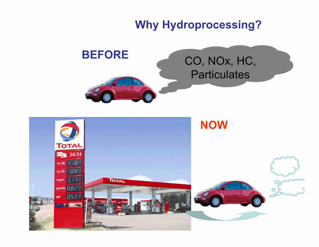
Why Hydroprocessing?
CO, NOx, HC, Particulates
BEFORE
NOW
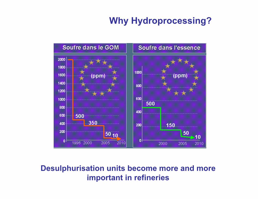
Why Hydroprocessing?
Desulphurisation units become more and more important in refineries
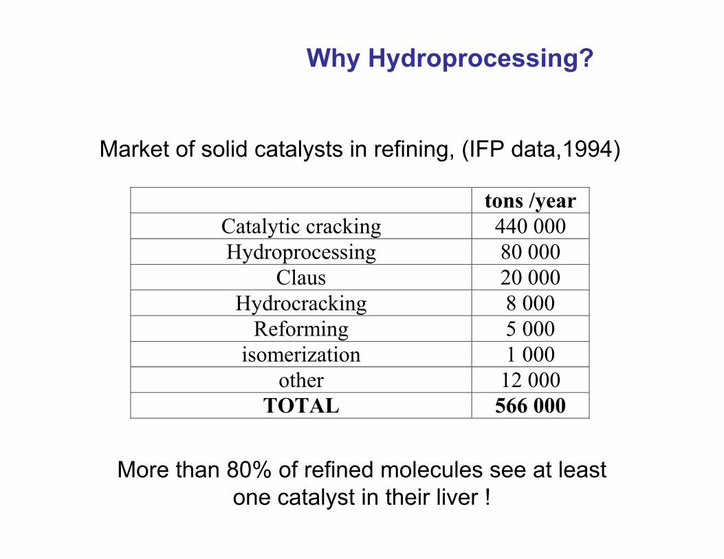
Market of solid catalysts in refining, (IFP data,1994)
tons /year Catalytic cracking 440 000 Hydroprocessing 80 000
Claus 20 000 Hydrocracking 8 000
Reforming 5 000 isomerization 1 000
other 12 000 TOTAL 566 000
More than 80% of refined molecules see at leastone catalyst in their liver !
Why Hydroprocessing?
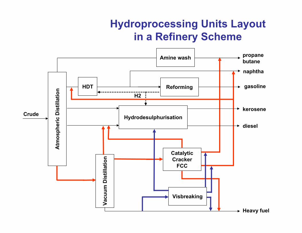
Hydroprocessing Units Layoutin a Refinery Scheme
Atm
osph
eric
Dis
tilla
tion
Heavy fuel
Crude
Vacu
um D
istil
latio
n
CatalyticCracker
FCC
Visbreaking
Reforming
propanebutane
gasoline
naphtha
Hydrodesulphurisationkerosene
diesel
H2
Amine wash
HDT
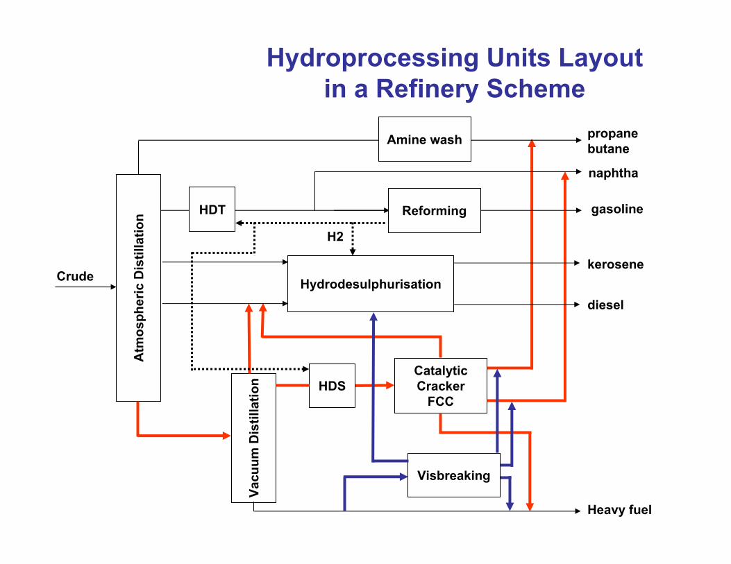
Hydroprocessing Units Layoutin a Refinery Scheme
Atm
osph
eric
Dis
tilla
tion
Heavy fuel
Crude
Vacu
um D
istil
latio
n
CatalyticCracker
FCC
Visbreaking
Reforming
propanebutane
gasoline
naphtha
Hydrodesulphurisationkerosene
diesel
H2
Amine wash
HDT
HDS
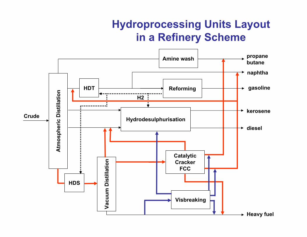
Hydroprocessing Units Layoutin a Refinery Scheme
Atm
osph
eric
Dis
tilla
tion
Heavy fuel
Crude
Vacu
um D
istil
latio
n
CatalyticCracker
FCC
Visbreaking
Reforming
propanebutane
gasoline
naphtha
Hydrodesulphurisationkerosene
diesel
H2
Amine wash
HDT
HDS
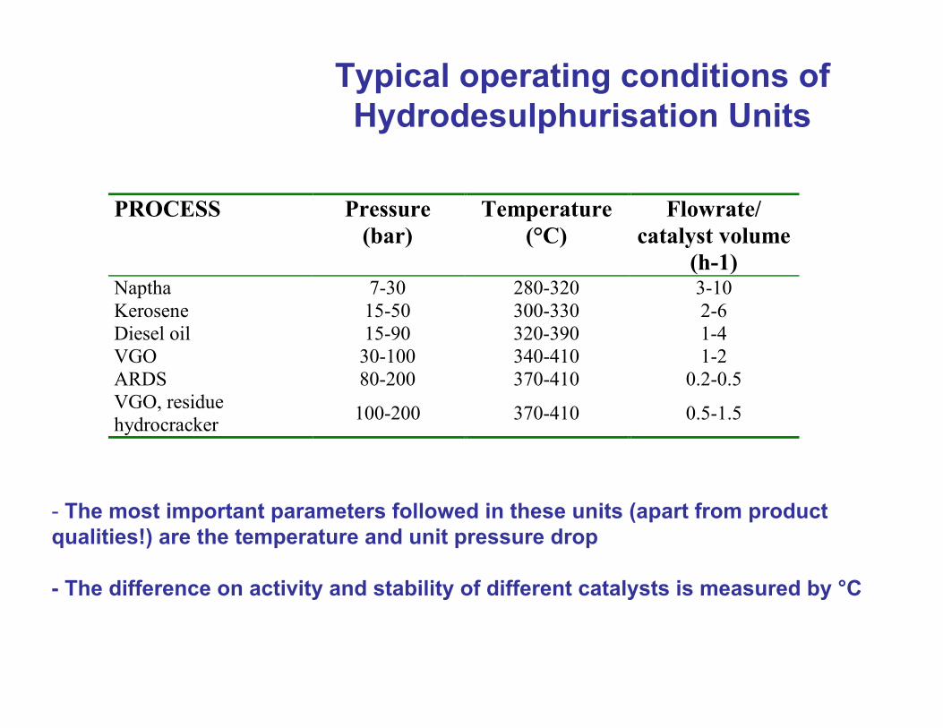
Typical operating conditions of Hydrodesulphurisation Units
PROCESS Pressure (bar)
Temperature (°C)
Flowrate/ catalyst volume
(h-1) Naptha 7-30 280-320 3-10 Kerosene 15-50 300-330 2-6 Diesel oil 15-90 320-390 1-4 VGO 30-100 340-410 1-2 ARDS 80-200 370-410 0.2-0.5 VGO, residue hydrocracker 100-200 370-410 0.5-1.5
- The most important parameters followed in these units (apart from product qualities!) are the temperature and unit pressure drop
- The difference on activity and stability of different catalysts is measured by °C
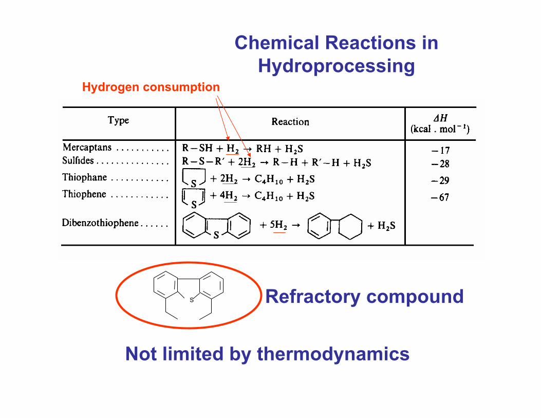
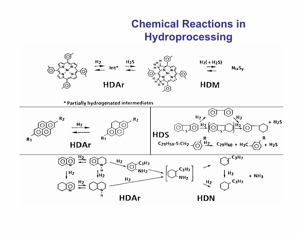
Chemical Reactions in Hydroprocessing
Not limited by thermodynamics
Refractory compoundS
Hydrogen consumption
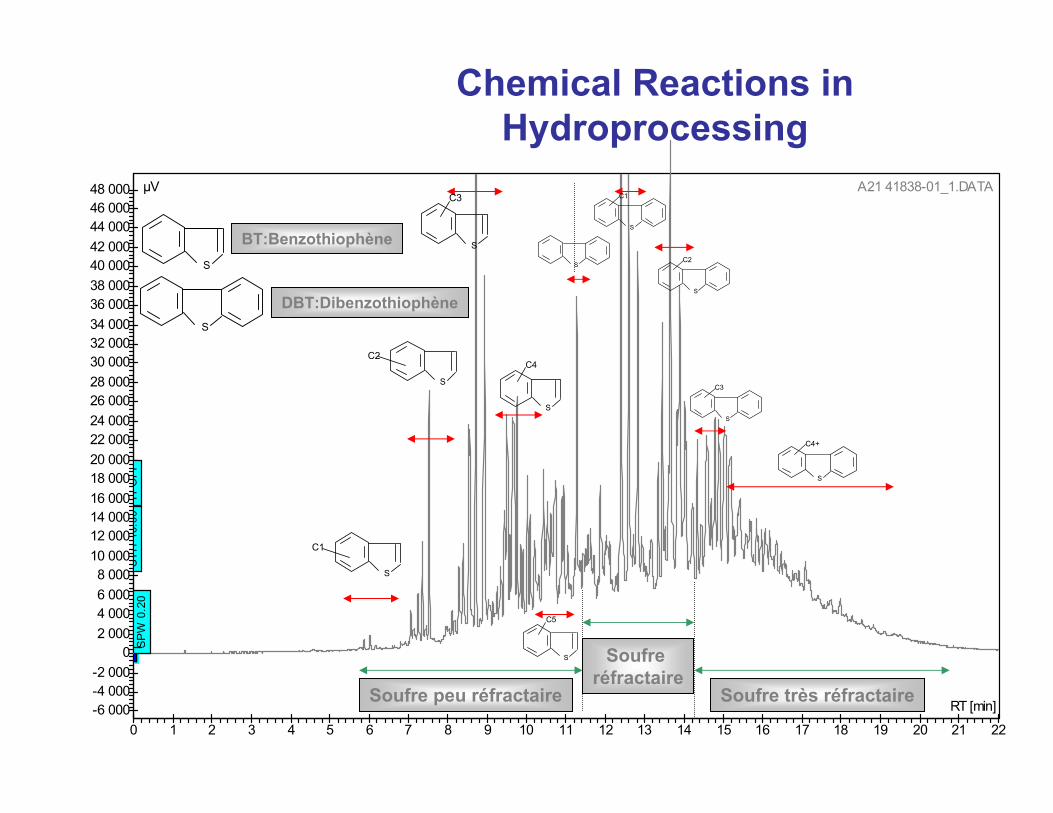
Chemical Reactions in Hydroprocessing
222120191817161514131211109876543210
48 00046 00044 00042 00040 00038 00036 00034 00032 00030 00028 00026 00024 00022 00020 00018 00016 00014 00012 00010 0008 0006 0004 0002 000
0-2 000-4 000-6 000
SP
W 0
.20
ST
H 1
0.00
TI
OF
F
RT [min]
µV A21 41838-01_1.DATA
S
C1
S
C2
S
C4
S
C3
S
S
C1
S
C2
S
C3
S
C4+
S
C5
Soufre peu réfractaire Soufre très réfractaire
Soufre réfractaire
S
S
BT:Benzothiophène
DBT:Dibenzothiophène
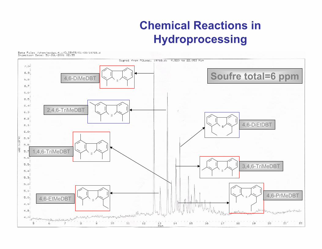
Soufre total=6 ppmS
S
S
S
S
S
S
4,6-EtMeDBT
1,4,6-TriMeDBT
2,4,6-TriMeDBT
4,6-DiMeDBT
4,6-DiEtDBT
3,4,6-TriMeDBT
4,6-PrMeDBT
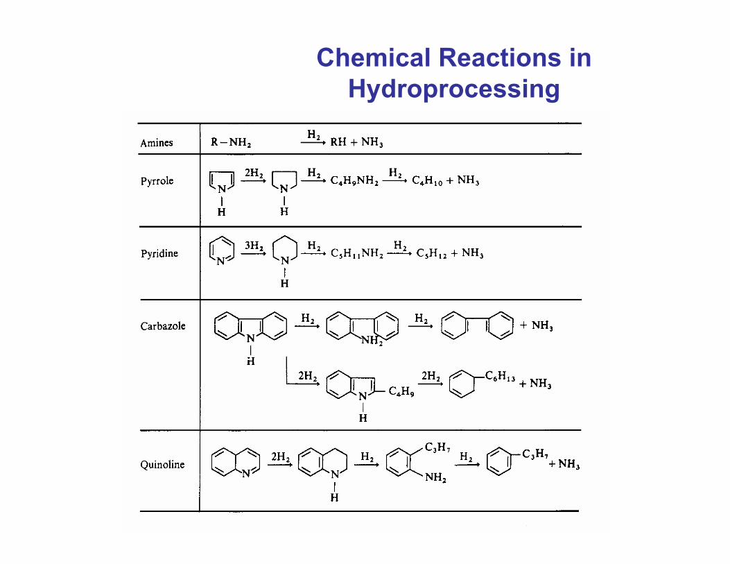
Chemical Reactions in Hydroprocessing
Chemical Reactions in Hydroprocessing
Chemical Reactions in Hydroprocessing
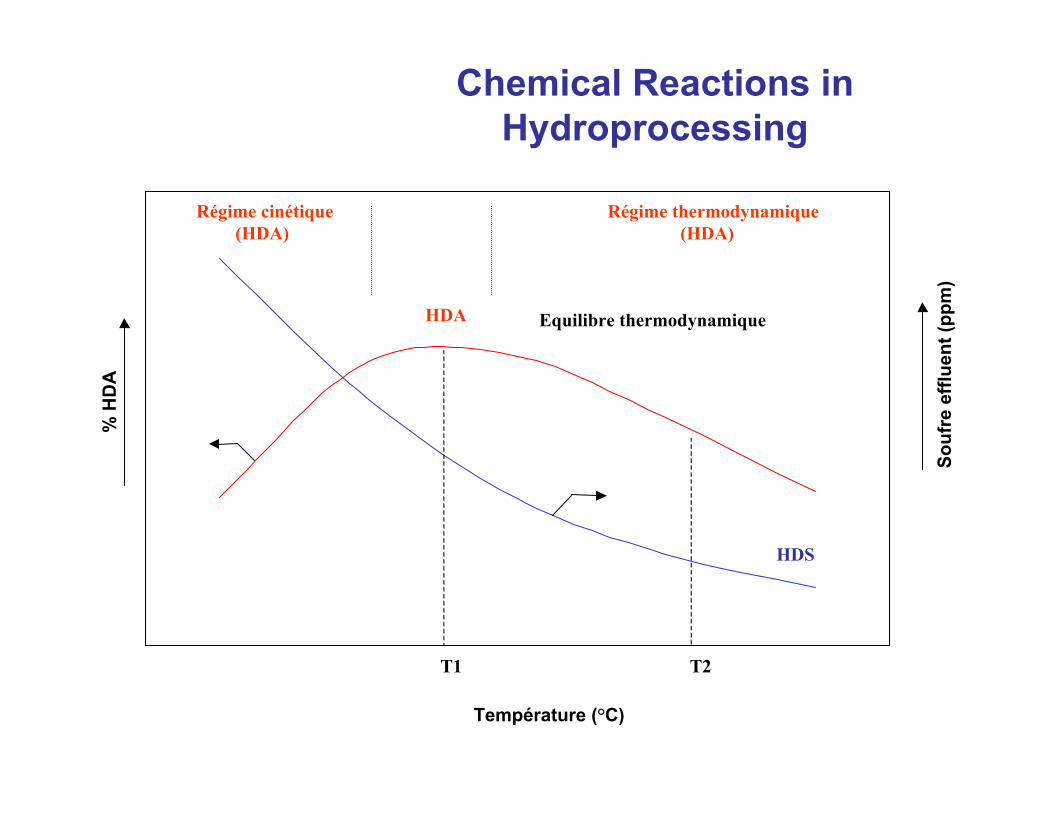
Température (°C)
% H
DA
Souf
re e
fflue
nt (p
pm)
T1 T2
HDS
Régime thermodynamique(HDA)
Régime cinétique(HDA)
Equilibre thermodynamiqueHDA
Chemical Reactions in Hydroprocessing
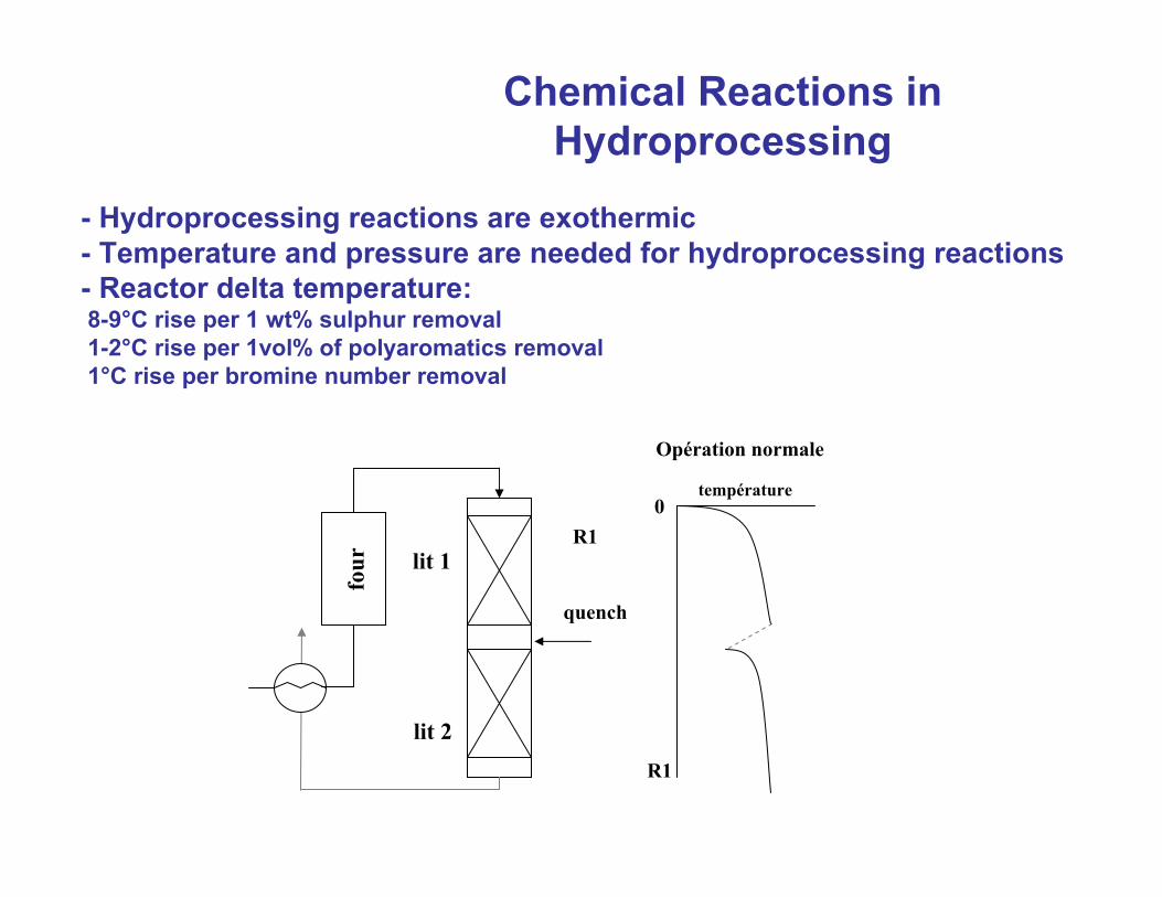
Chemical Reactions in Hydroprocessing
- Hydroprocessing reactions are exothermic- Temperature and pressure are needed for hydroprocessing reactions- Reactor delta temperature:8-9°C rise per 1 wt% sulphur removal1-2°C rise per 1vol% of polyaromatics removal1°C rise per bromine number removal
quench
four lit 1
lit 2
0
R1
Opération normale
R1
température
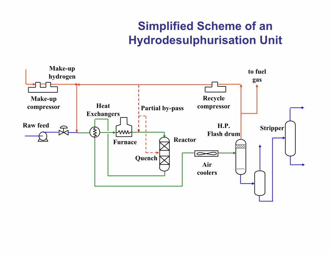
Simplified Scheme of an Hydrodesulphurisation Unit
2
Partial by-passRecycle
compressor
Raw feed
Make-up compressor
Make-up hydrogen
to fuel gas
H.P.Flash drum
Furnace Reactor
Air coolers
Heat Exchangers
Stripper
Quench
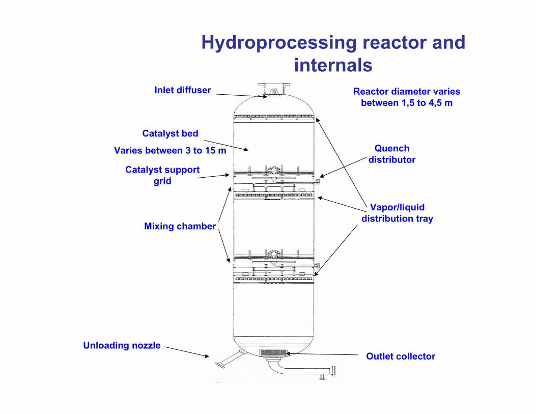
Hydroprocessing reactor and internals
Vapor/liquid distribution tray
Catalyst bed
Varies between 3 to 15 m
Catalyst support grid
Quench distributor
Mixing chamber
Outlet collector
Inlet diffuser
Unloading nozzle
Reactor diameter varies between 1,5 to 4,5 m
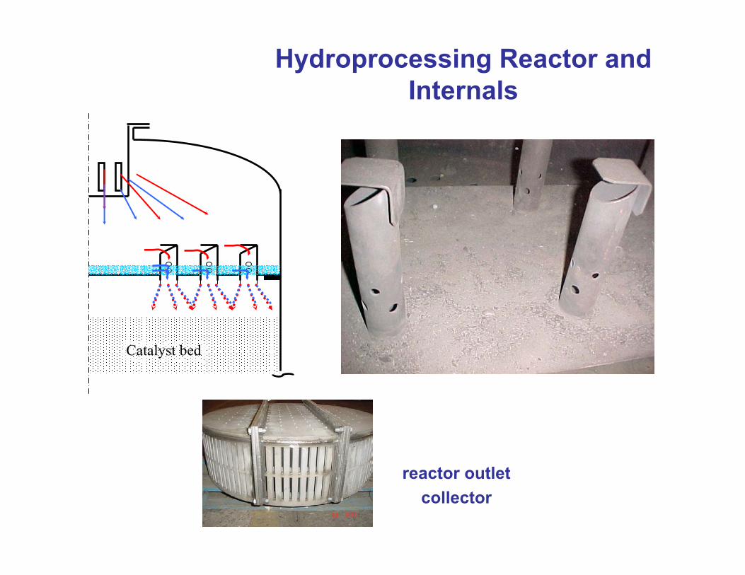
Hydroprocessing Reactor and Internals
Catalyst bed
reactor outlet collector
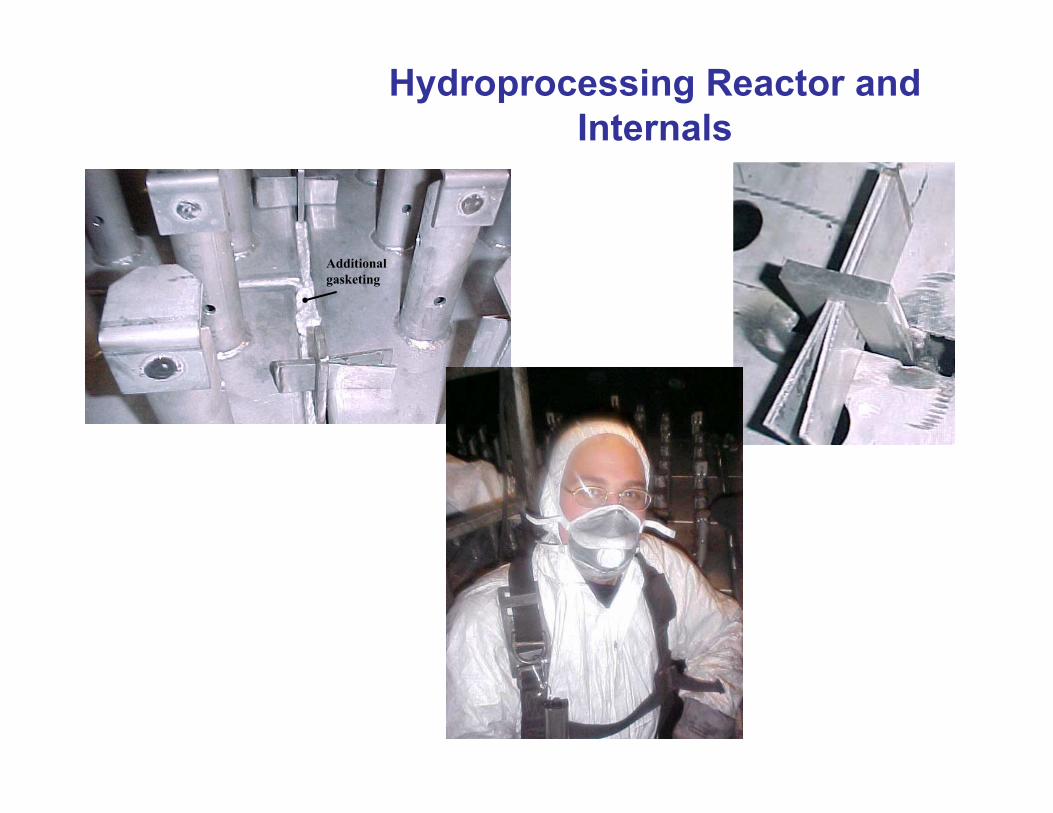
Hydroprocessing Reactor and Internals
Additional gasketing
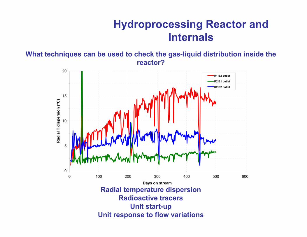
Hydroprocessing Reactor and Internals
What techniques can be used to check the gas-liquid distribution inside the reactor?
0
5
10
15
20
0 100 200 300 400 500 600
Days on stream
Rad
ial T
dis
pers
ion
(°C
)
R1 B2 outlet
R2 B1 outlet
R2 B2 outlet
Radial temperature dispersionRadioactive tracers
Unit start-upUnit response to flow variations
Hydroprocessing Catalysts
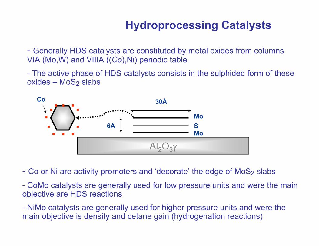
- Generally HDS catalysts are constituted by metal oxides from columns VIA (Mo,W) and VIIIA ((Co),Ni) periodic table
- The active phase of HDS catalysts consists in the sulphided form of these oxides – MoS2 slabs
Al2O3γ
Mo
MoS6Å
30Å
.. .. ... .. . .
- Co or Ni are activity promoters and ‘decorate’ the edge of MoS2 slabs
- CoMo catalysts are generally used for low pressure units and were the main objective are HDS reactions
- NiMo catalysts are generally used for higher pressure units and were the main objective is density and cetane gain (hydrogenation reactions)
Co
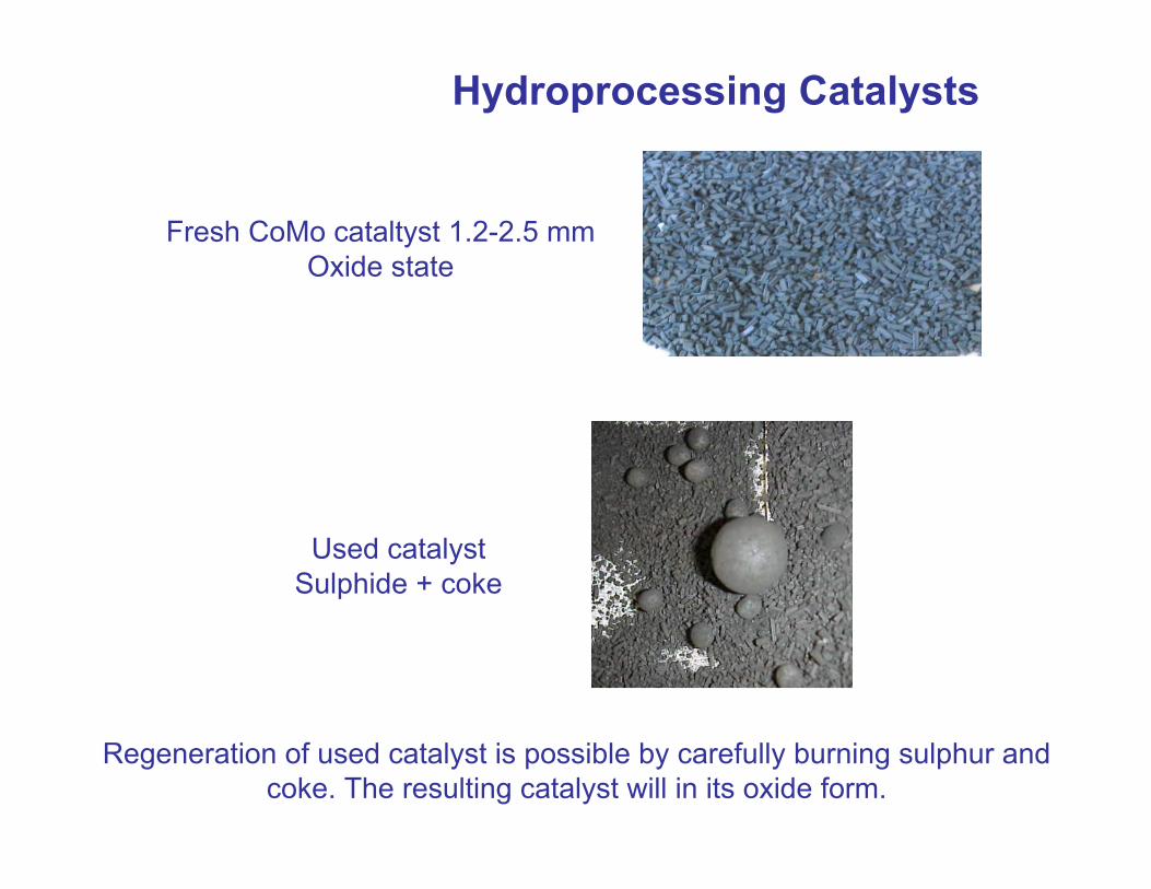
Hydroprocessing Catalysts
Used catalystSulphide + coke
Regeneration of used catalyst is possible by carefully burning sulphur and coke. The resulting catalyst will in its oxide form.
Fresh CoMo cataltyst 1.2-2.5 mmOxide state
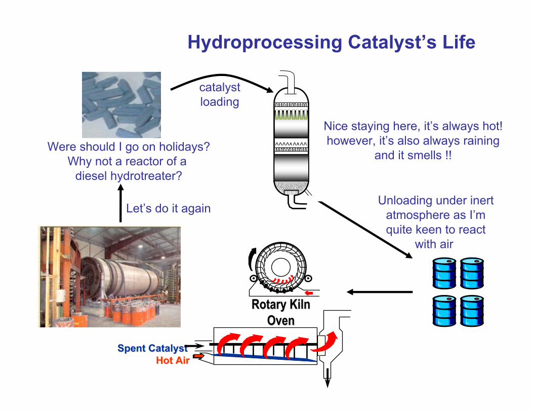
Hydroprocessing Catalyst’s Life
Were should I go on holidays?Why not a reactor of a
diesel hydrotreater?
Unloading under inertatmosphere as I’mquite keen to react
with air
RotaryRotary Kiln Kiln OvenOven
Spent CatalystSpent CatalystHot AirHot Air
Let’s do it again
Nice staying here, it’s always hot!however, it’s also always raining
and it smells !!
catalystloading
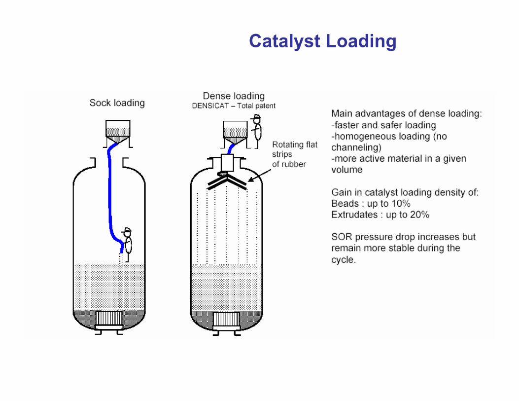
Catalyst Loading
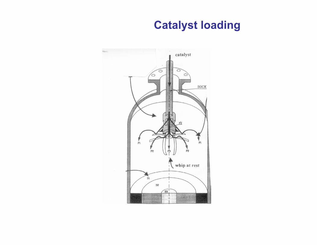
Catalyst loading
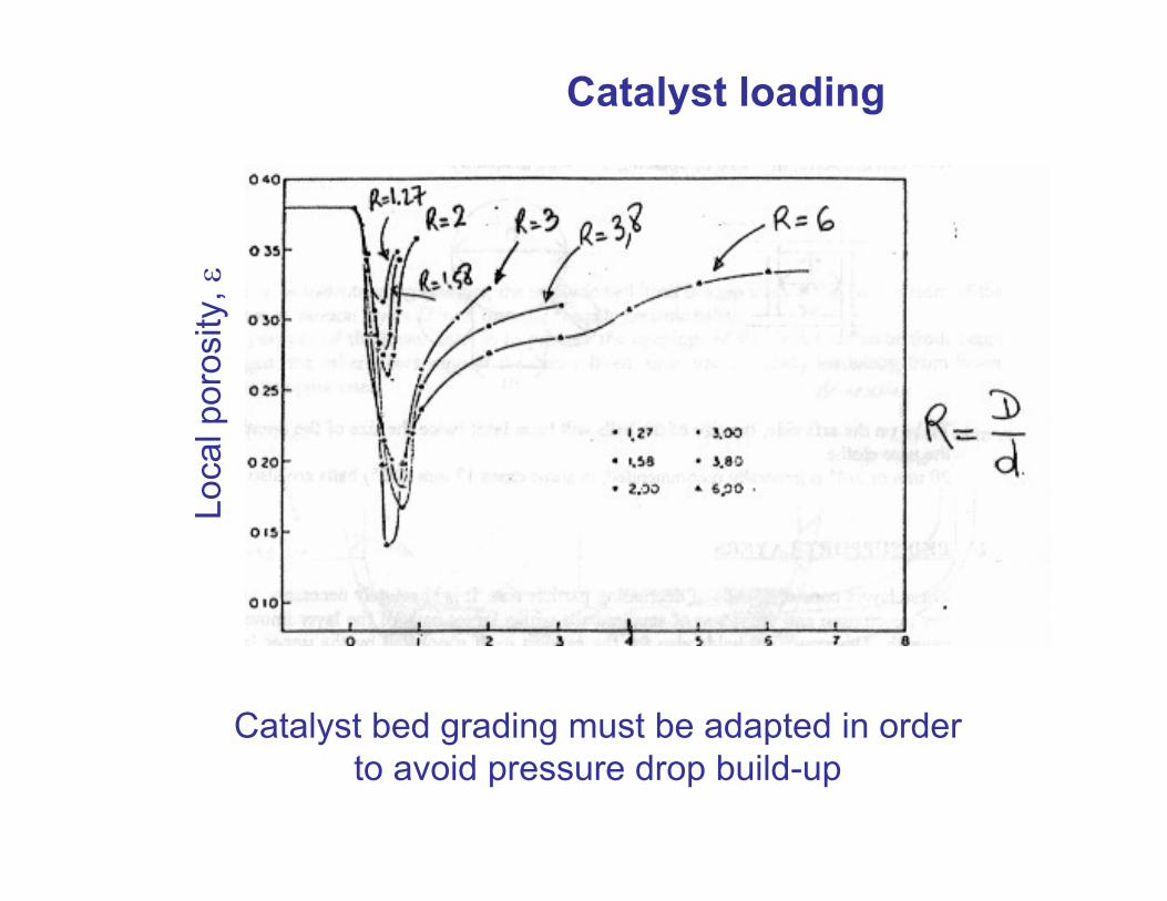
Catalyst loading
Loca
l por
osity
, ε
Catalyst bed grading must be adapted in orderto avoid pressure drop build-up
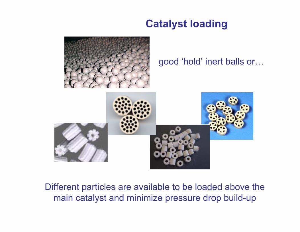
Catalyst loading
Different particles are available to be loaded above themain catalyst and minimize pressure drop build-up
good ‘hold’ inert balls or…
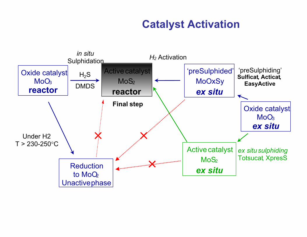
Catalyst Activation
Oxide catalystMoO3
reactor
Reductionto MoO2
Unactive phase
Under H2T > 230-250°C
Oxide catalystMoO3
ex situ
‘preSulphided’MoOxSyex situ
Active catalystMoS2
reactor
in situSulphidation
‘preSulphiding’Sulficat, Acticat,
EasyActive
H2 Activation
Active catalystMoS2
ex situ
ex situ sulphidingTotsucat, XpresS
H2S
DMDS
Final step
Catalyst Activation
Rea
ctor
inle
t tem
pera
ture
(°C
)
350
300
250
200
150
100
50
00 2 4 6 8 10 12 14 16 18 20
Time (hours)
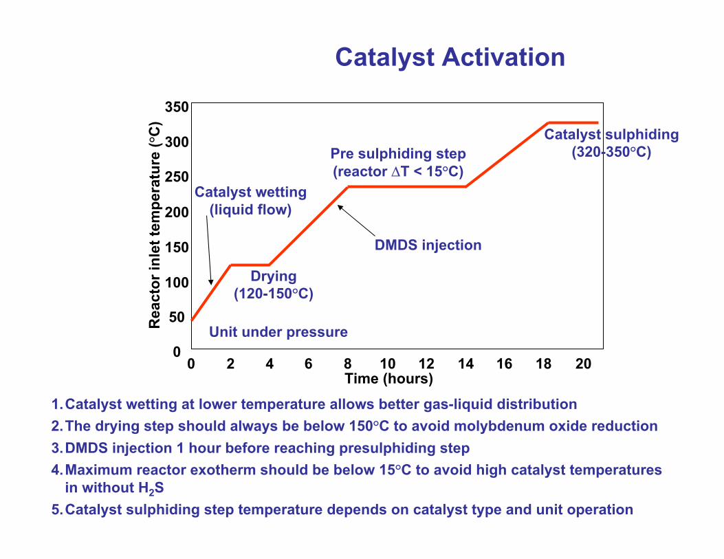
Drying(120-150°C)
Pre sulphiding step(reactor ∆T < 15°C)
Catalyst sulphiding(320-350°C)
Catalyst wetting(liquid flow)
1.Catalyst wetting at lower temperature allows better gas-liquid distribution2.The drying step should always be below 150°C to avoid molybdenum oxide reduction3.DMDS injection 1 hour before reaching presulphiding step4.Maximum reactor exotherm should be below 15°C to avoid high catalyst temperatures
in without H2S5.Catalyst sulphiding step temperature depends on catalyst type and unit operation
DMDS injection
Unit under pressure
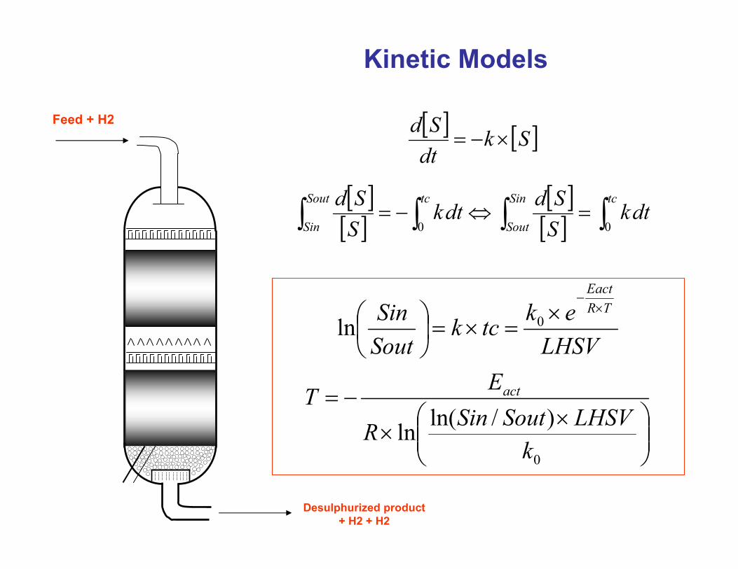
Kinetic Models
Feed + H2
Desulphurized product+ H2 + H2
[ ] [ ]SkdtSd
×−=
LHSVektck
SoutSin TR
Eact×
−×
=×=
0ln
××
−=
0
)/ln(lnk
LHSVSoutSinR
ET act
[ ][ ]
[ ][ ] ∫∫∫∫ =⇔−=
tcSin
Sout
tcSout
Sindtk
SSddtk
SSd
00
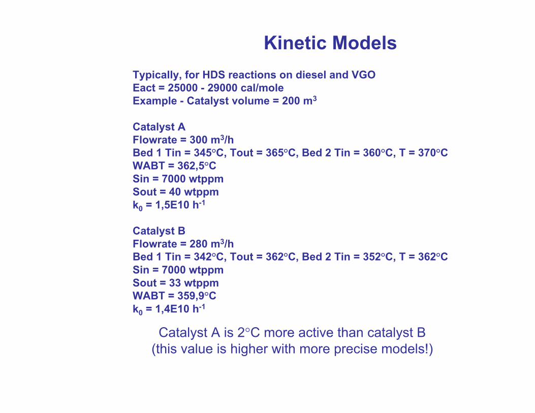
Kinetic ModelsTypically, for HDS reactions on diesel and VGO Eact = 25000 - 29000 cal/moleExample - Catalyst volume = 200 m3
Catalyst AFlowrate = 300 m3/hBed 1 Tin = 345°C, Tout = 365°C, Bed 2 Tin = 360°C, T = 370°CWABT = 362,5°CSin = 7000 wtppmSout = 40 wtppmk0 = 1,5E10 h-1
Catalyst BFlowrate = 280 m3/hBed 1 Tin = 342°C, Tout = 362°C, Bed 2 Tin = 352°C, T = 362°CSin = 7000 wtppmSout = 33 wtppmWABT = 359,9°Ck0 = 1,4E10 h-1
Catalyst A is 2°C more active than catalyst B(this value is higher with more precise models!)
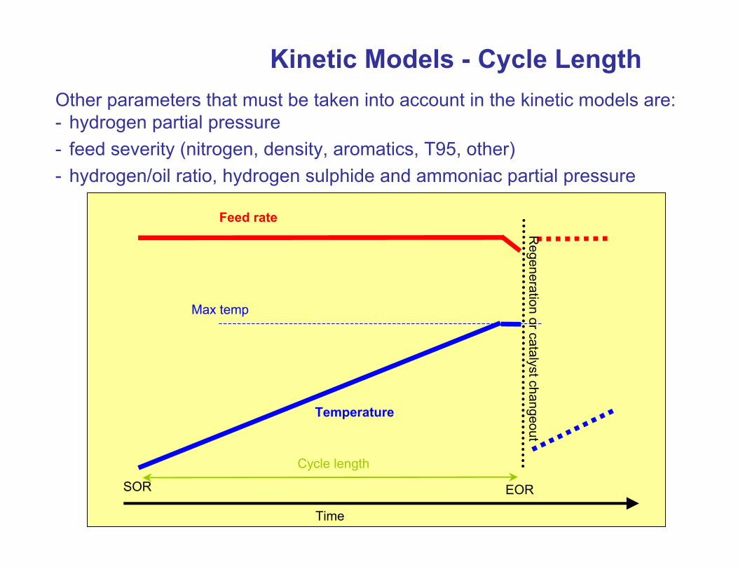
Kinetic Models - Cycle LengthOther parameters that must be taken into account in the kinetic models are:- hydrogen partial pressure- feed severity (nitrogen, density, aromatics, T95, other)- hydrogen/oil ratio, hydrogen sulphide and ammoniac partial pressure
Time
SOR EOR
Feed rate
Max temp
Cycle length
Regeneration or catalyst changeout
Temperature
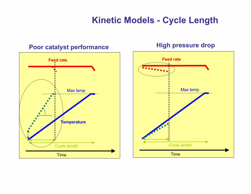
Kinetic Models - Cycle Length
Time
Feed rate
Max temp
Cycle length
Temperature
Time
Feed rate
Max temp
Cycle length
Poor catalyst performance High pressure drop
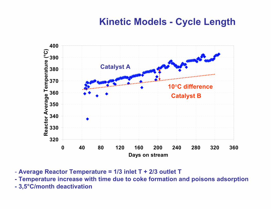
Kinetic Models - Cycle Length
- Average Reactor Temperature = 1/3 inlet T + 2/3 outlet T- Temperature increase with time due to coke formation and poisons adsorption- 3,5°C/month deactivation
320
330
340
350
360
370
380
390
400
0 40 80 120 160 200 240 280 320 360Days on stream
Rea
ctor
Ave
rage
Tem
pera
ture
(°C
)
10°C differenceCatalyst B
Catalyst A
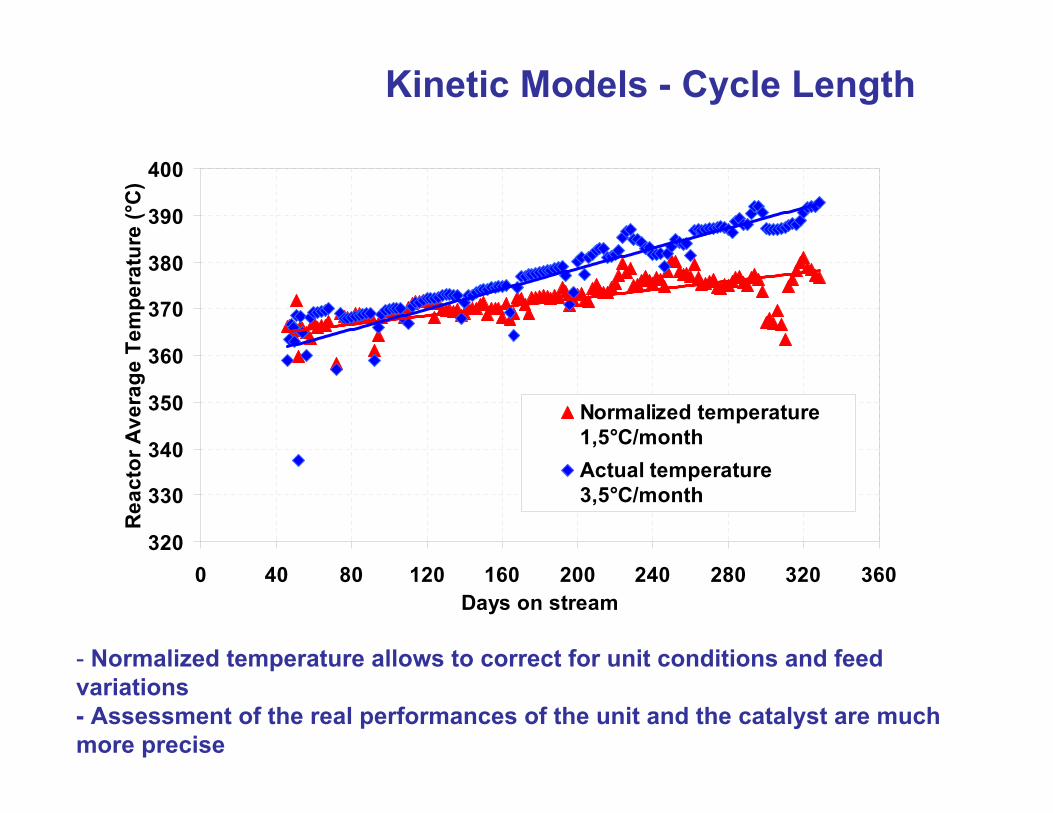
Kinetic Models - Cycle Length
320
330
340
350
360
370
380
390
400
0 40 80 120 160 200 240 280 320 360Days on stream
Rea
ctor
Ave
rage
Tem
pera
ture
(°C
)
Normalized temperature1,5°C/monthActual temperature3,5°C/month
- Normalized temperature allows to correct for unit conditions and feed variations- Assessment of the real performances of the unit and the catalyst are much more precise
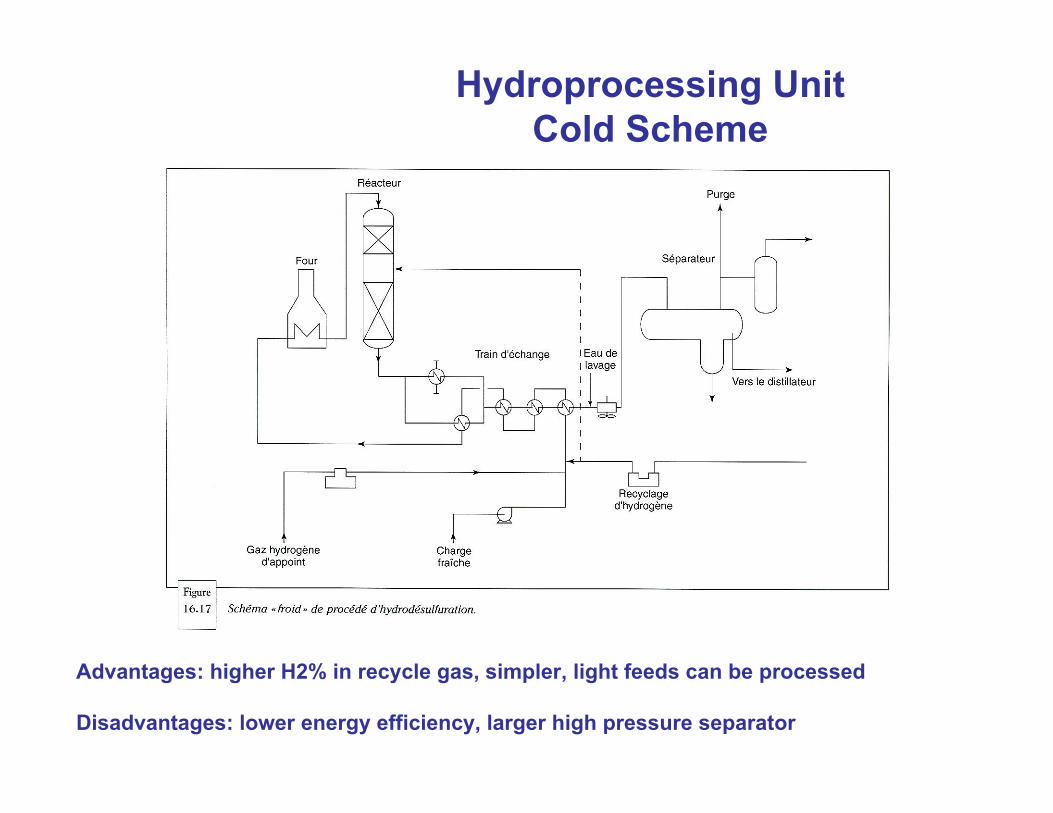
Hydroprocessing UnitCold Scheme
Advantages: higher H2% in recycle gas, simpler, light feeds can be processed
Disadvantages: lower energy efficiency, larger high pressure separator
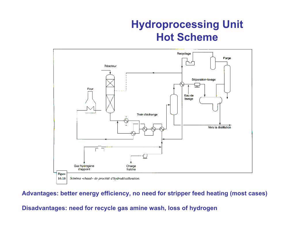
Hydroprocessing UnitHot Scheme
Advantages: better energy efficiency, no need for stripper feed heating (most cases)
Disadvantages: need for recycle gas amine wash, loss of hydrogen
Hydroprocessing UnitStripping section
The objective of the stripping section is to removed light ends from the diesel (H2S, CH’s) and/or to remove products lighter than the unit main product
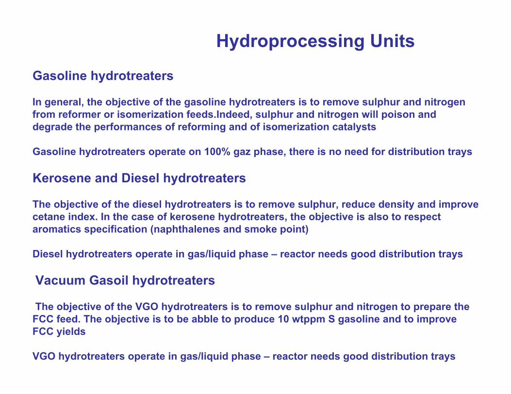
Gasoline hydrotreaters
In general, the objective of the gasoline hydrotreaters is to remove sulphur and nitrogen from reformer or isomerization feeds.Indeed, sulphur and nitrogen will poison and degrade the performances of reforming and of isomerization catalysts
Gasoline hydrotreaters operate on 100% gaz phase, there is no need for distribution trays
Kerosene and Diesel hydrotreaters
The objective of the diesel hydrotreaters is to remove sulphur, reduce density and improve cetane index. In the case of kerosene hydrotreaters, the objective is also to respect aromatics specification (naphthalenes and smoke point)
Diesel hydrotreaters operate in gas/liquid phase – reactor needs good distribution trays
Vacuum Gasoil hydrotreaters
The objective of the VGO hydrotreaters is to remove sulphur and nitrogen to prepare the FCC feed. The objective is to be abble to produce 10 wtppm S gasoline and to improve FCC yields
VGO hydrotreaters operate in gas/liquid phase – reactor needs good distribution trays
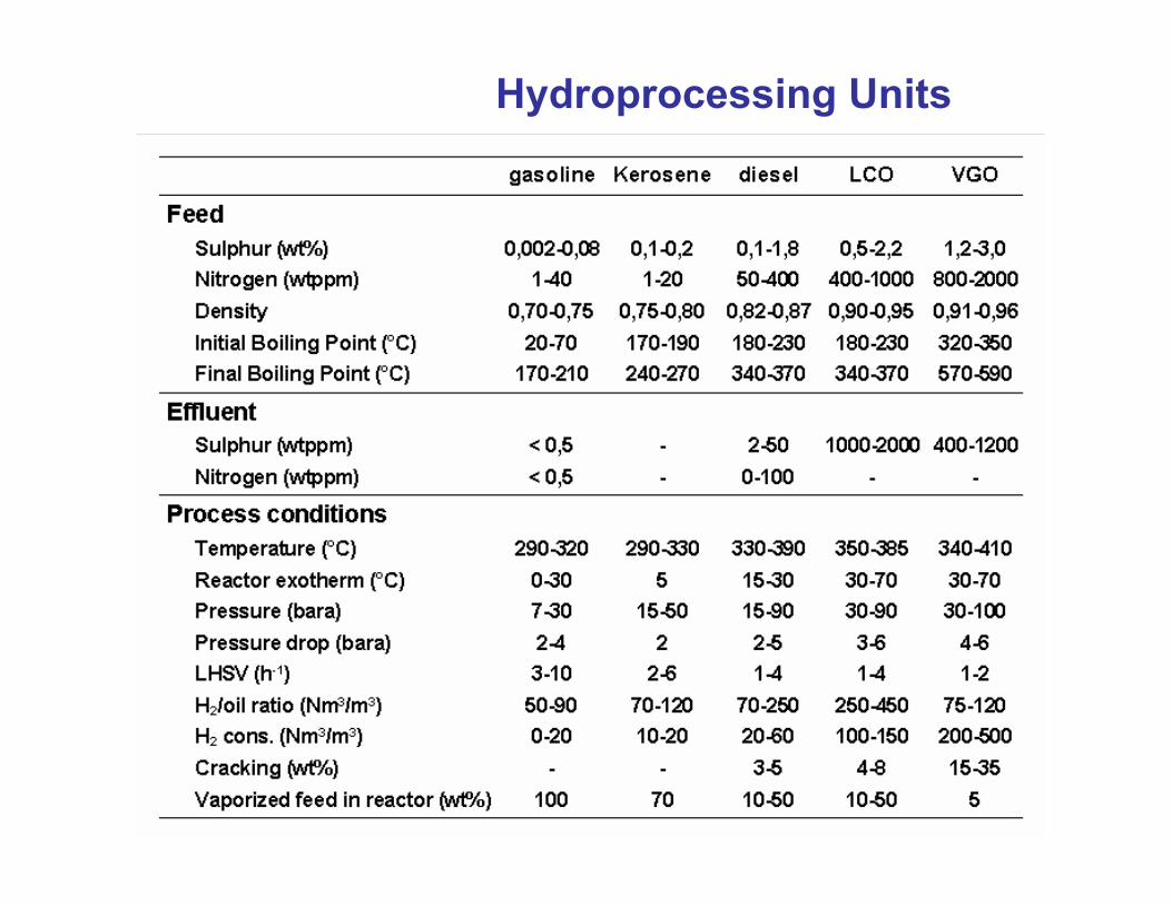
Hydroprocessing Units
Hydroprocessing Units
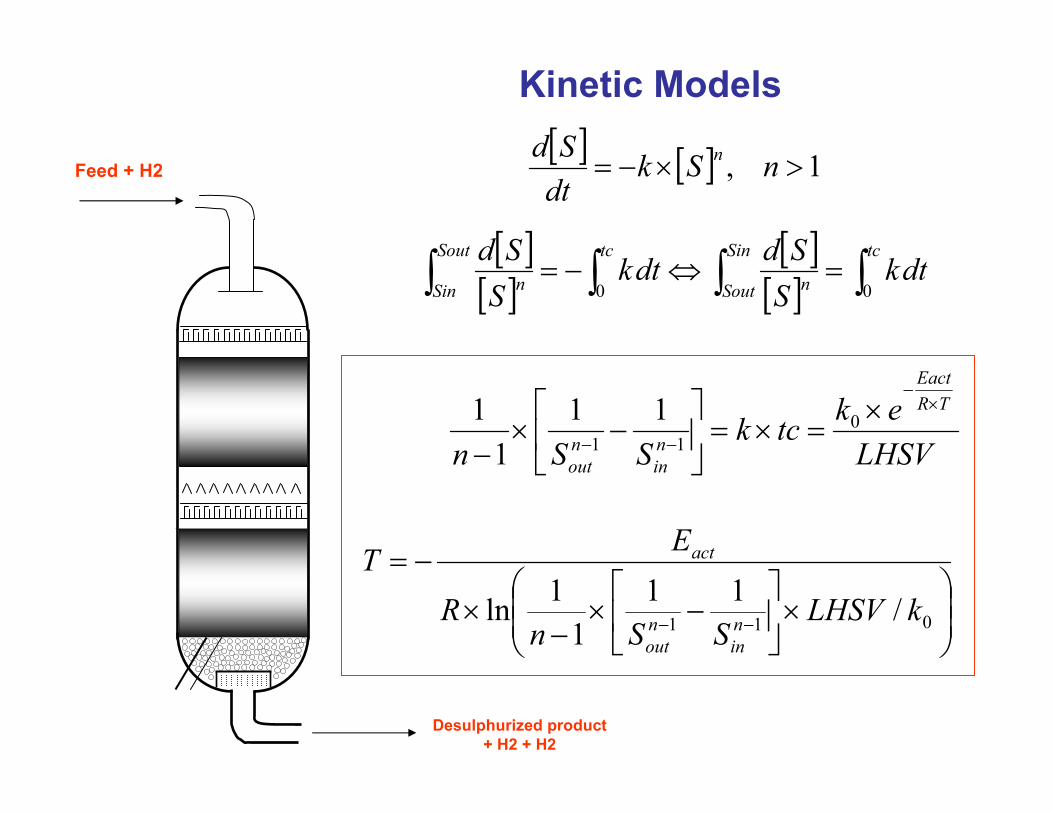
Kinetic Models
Feed + H2
Desulphurized product+ H2 + H2
[ ] [ ] 1, >×−= nSkdtSd n
LHSVektck
SSn
TREact
nin
nout
×−
−−
×=×=
−×
−0
11
111
1
×
−×
−×
−=
−− 011 /111
1ln kLHSVSSn
R
ET
nin
nout
act
[ ][ ]
[ ][ ] ∫∫∫∫ =⇔−=
tcSin
Sout n
tcSout
Sin n dtkSSddtk
SSd
00