CYLINDER UNITEHST20 seriesEHPT20 series
HYDROBOXEHSC series EHSD seriesEHPX series ERSC seriesERSD series
MODE D'EMPLOIPour garantir une utilisation sûre et appropriée, lisez attentivement le présent mode d'emploi avant d'utiliser l’ECODAN hydrobox duo et l’ECODAN hydrobox.
BEDIENUNGSANLEITUNGLesen Sie sich zur sicheren und korrekten Verwendung diese Bedienungsanleitung bitte sorgfältig durch, bevor Sie das Hydraulikmodul inkl. Speicher und die Hydrobox verwenden.
FÜR NUTZER
OPERATION MANUALFor safe and correct use, please read this operation manual thoroughly before operating the cylinder unit and the hydrobox.
HANDLEIDINGVoor een veilig en juist gebruik moet u deze handleiding goed doorlezen alvorens de cilinder en hydrobox in gebruik te nemen.
MANUAL DE INSTRUCCIONESPara un uso correcto y seguro del hydrobox duo y del Hydrobox, lea este manual de instrucciones antes de su utilización.
MANUALE DI FUNZIONAMENTOPer un uso corretto e sicuro del dispositivo, leggere attentamente il presente manuale di funzionamento prima di utilizzare l’hydrotank e l’hydrobox.
MANUAL DE FUNCIONAMENTOPara uma utilização segura e correcta, é favor ler cuidadosamente este manual de funcionamento antes de trabalhar com o cilindro e permutador de calor.
BRUGSVEJLEDNINGLæs venligst denne brugsvejledning grundigt inden betjening af i tank modulet (unit) og hydroboksen.
ANVÄNDARMANUALFör säker och korrekt användning, var god läs denna användarmanual noggrant innan du använder i cylindertanken och hydroboxen.
BRUKSANVISNINGLes denne bruksanvisningen nøye før du bruker sylinderenheten og hydroboksen for å sikre trygg og riktig bruk.
KÄYTTÖOPASTurvallisen ja asianmukaisen käytön varmistamiseksi lue tämä käyttöopas huolellisesti ennen varaajayksikön ja hydroboxin käyttöä.
KÄYTTÄJÄLLE
FOR BRUKEREN
FOR USER
POUR LES UTILISATEURS
VOOR DE GEBRUIKER
PARA EL USUARIO
PER L’UTENTE
PARA O UTILIZADOR
TIL BRUGER
FÖR ANVÄNDAREN
English (EN)
(RU)
Español (ES)
Italiano (IT)
Português (PT)
Dansk (DA)
Svenska (SV)
Norsk (NO)
Suomi (FI)
Deutsch (DE)
Français (FR)
Nederlands (NL)
-
1
EN
Contents1. Safety Precautions ........................................... 2
2. Introduction ....................................................... 3
3. Your Heating System ........................................ 5
4. Customising Settings for Your Home ............. 7
5. Service and Maintenance............................... 14
Abbreviations and glossary
No. Abbreviations/Word Description1 Compensation curve mode Space heating incorporating outdoor ambient temperature compensation2 COP3 Cooling mode4 Cylinder unit Indoor unvented DHW tank and component plumbing parts5 DHW mode Domestic hot water heating mode for showers, sinks, etc6 Flow temperature Temperature at which water is delivered to the primary circuit7 Freeze stat. function Heating control routine to prevent water pipes freezing8 FTC Flow temperature controller, the circuit board in charge of controlling the system9 Heating mode10 Hydrobox Indoor unit housing the component plumbing parts (NO DHW tank)11 Legionella Bacteria potentially found in plumbing, showers and water tanks that may cause Legionnaires disease12 LP mode Legionella prevention mode – a function on systems with water tanks to prevent the growth of legionella bacterium13 Packaged model Plate heat exchanger (Refrigerant - Water) in the outdoor heat pump unit14 PRV Pressure relief valve15 Return temperature Temperature at which water is delivered from the primary circuit16 Split model Plate heat exchanger (Refrigerant - Water) in the indoor unit17 TRV Thermostatic radiator valve – a valve on the entrance or exit of the radiator panel to control the heat output
2
Safety Precautions1EN
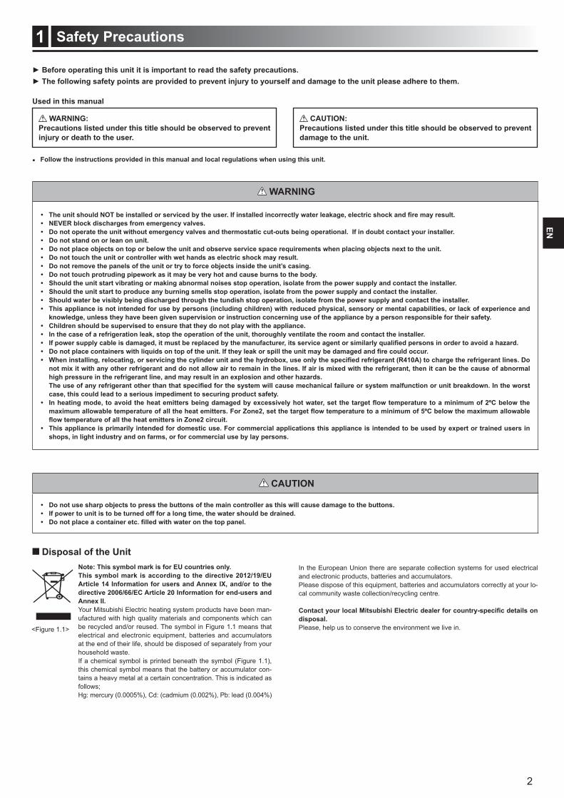
Disposal of the UnitNote: This symbol mark is for EU countries only.This symbol mark is according to the directive 2012/19/EU
Annex II.Your Mitsubishi Electric heating system products have been man-ufactured with high quality materials and components which can be recycled and/or reused. The symbol in Figure 1.1 means that electrical and electronic equipment, batteries and accumulators at the end of their life, should be disposed of separately from your household waste. If a chemical symbol is printed beneath the symbol (Figure 1.1), this chemical symbol means that the battery or accumulator con-tains a heavy metal at a certain concentration. This is indicated as follows;Hg: mercury (0.0005%), Cd: (cadmium (0.002%), Pb: lead (0.004%)
In the European Union there are separate collection systems for used electrical and electronic products, batteries and accumulators.Please dispose of this equipment, batteries and accumulators correctly at your lo-cal community waste collection/recycling centre.
disposal. Please, help us to conserve the environment we live in.
WARNING
CAUTION
<Figure 1.1>
Follow the instructions provided in this manual and local regulations when using this unit.
Used in this manual
WARNING:Precautions listed under this title should be observed to prevent
CAUTION:Precautions listed under this title should be observed to prevent damage to the unit.
2 kW
3 kW1 kW
4. Evaporator(Outdoor unit air heat exchanger)Low temperature renewable heat
energy taken from the environment
Electrical energy input
Heat energy output
2. Condenser(Plate heat exchanger)
1. Compressor3. Expansion valve
3
Introduction2EN
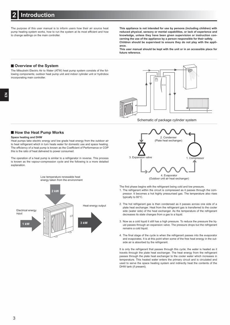
Schematic of package cylinder system
Overview of the SystemThe Mitsubishi Electric Air to Water (ATW) heat pump system consists of the fol-lowing components; outdoor heat pump unit and indoor cylinder unit or hydrobox incorporating main controller.
How the Heat Pump WorksSpace heating and DHWHeat pumps take electric energy and low grade heat energy from the outdoor air to heat refrigerant which in turn heats water for domestic use and space heating.
this is the ratio of heat delivered to power consumed. The operation of a heat pump is similar to a refrigerator in reverse. This process is known as the vapour-compression cycle and the following is a more detailed explanation.
1. The refrigerant within the circuit is compressed as it passes through the com-pressor. It becomes a hot highly pressurised gas. The temperature also rises typically to 60°C.
2. The hot refrigerant gas is then condensed as it passes across one side of a plate heat exchanger. Heat from the refrigerant gas is transferred to the cooler side (water side) of the heat exchanger. As the temperature of the refrigerant decreases its state changes from a gas to a liquid.
3. Now as a cold liquid it still has a high pressure. To reduce the pressure the liq-uid passes through an expansion valve. The pressure drops but the refrigerant remains a cold liquid.
and evaporates. It is at this point when some of the free heat energy in the out-side air is absorbed by the refrigerant.
It is only the refrigerant that passes through this cycle; the water is heated as it travels through the plate heat exchanger. The heat energy from the refrigerant passes through the plate heat exchanger to the cooler water which increases in temperature. This heated water enters the primary circuit and is circulated and used to serve the space heating system and indirectly heat the contents of the DHW tank (if present).
The purpose of this user manual is to inform users how their air source heat
to change settings on the main controller.
This appliance is not intended for use by persons (including children) with
cerning the use of the appliance by a person responsible for their safety.Children should be supervised to ensure they do not play with the appliance.This user manual should be kept with the unit or in an accessible place for future reference.

20°C
4
Introduction2EN
Room temp sensor
Return temp sensor
Flow temp sensor
Ambient temp sensor
FTC
Economical Best PracticeAir source heat pumps can provide both hot water (providing a suitable DHW tank is used) and space heating all year. The system is different to a conventional fossil
heating system.
Important points about heat pump systems
or hydroboxes plumbed to an appropriate storage DHW tank.
However during periods of extremely low outdoor ambient temperature, the im-mersion heater (if present) can be used for DHW whilst the heat pump contin-ues to provide space heating. Please be aware that the immersion heater, used
should only be used as a back up in normal operation.
than a fossil fuel boiler.
Implications
should be scheduled using the SCHEDULE function (see page 12). Ideally this should be during the night time when little space heating is required and economy electricity tariffs can be taken advantage of.
-ture mode. This enables the heat pump to analyse current room temperature and react to changes in a controlled manner utilising the specialised Mitsubi-shi Electric controls.
or DHW heating when the property is known to be unoccupied for instance during the working day.
costs of the system as the heat pump does not have to produce water at very
Overview of ControlsBuilt into the cylinder unit and hydrobox is the Flow Temperature Controller(FTC). This device controls the function of both the outdoor heat pump unit and the cyl-inder unit or hydrobox. The advanced technology means that by using an FTC controlled heat pump you can not only make savings compared to traditional fos-sil fuel type heating systems but also compared to many other heat pumps on the market.
As explained in the earlier section, ‘How the Heat Pump Works,’ heat pumps are most efficient when providing low flow temperature water. The FTC advanced technology enables the room temperature to be kept at the desired level whilst
In room temp (Auto adaptation) mode the controller uses temperature sensors
is regularly updated and compared to previous data by the controller to predict
space heating circuit accordingly. By monitoring not only the outdoor ambient, but the room and heating circuit water temperatures, the heating is more consistent and sudden spikes in required heat output are reduced. This results in a lower
5
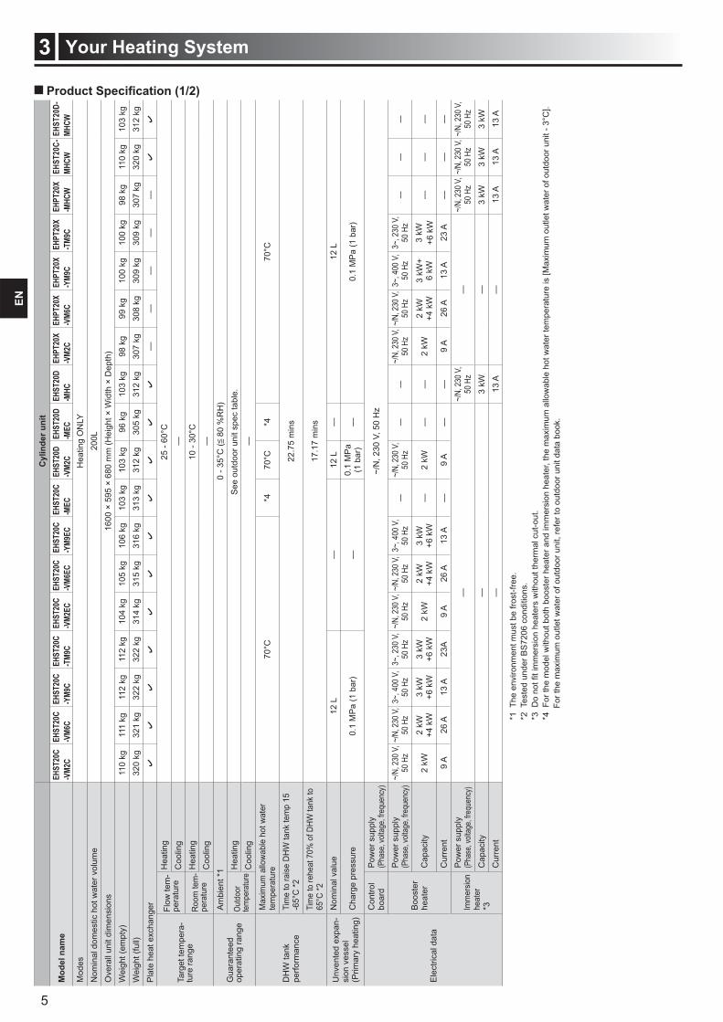
Your Heating System3EN
*1 T
he e
nviro
nmen
t mus
t be
frost
-free
.*2
Tes
ted
unde
r BS
7206
con
ditio
ns.
*4 F
or th
e m
odel
with
out b
oth
boos
ter h
eate
r and
imm
ersi
on h
eate
r, th
e m
axim
um a
llow
able
hot
wat
er te
mpe
ratu
re is
[Max
imum
out
let w
ater
of o
utdo
or u
nit -
3°C
].
For
the
max
imum
out
let w
ater
of o
utdo
or u
nit,
refe
r to
outd
oor u
nit d
ata
book
.
Cyl
inde
r uni
t
Mod
el n
ame
EHST
20C
EHST
20C
EHST
20C
EHST
20C
EHST
20C
EHST
20C
EHST
20C
EHST
20C
EHST
20D
EHST
20D
EHST
20D
EHPT
20X
EHPT
20X
EHPT
20X
EHPT
20X
EHPT
20X
MHCW
MHCW
Mod
esH
eatin
g O
NLY
Nom
inal
dom
estic
hot
wat
er v
olum
e20
0LO
vera
ll un
it di
men
sion
s16
00 ×
595
× 6
80 m
m (H
eigh
t × W
idth
× D
epth
)W
eigh
t (em
pty)
110
kg11
1 kg
112
kg11
2 kg
104
kg10
5 kg
106
kg10
3 kg
103
kg96
kg
103
kg98
kg
99 k
g10
0 kg
100
kg98
kg
110
kg10
3 kg
Wei
ght (
full)
320
kg32
1 kg
322
kg32
2 kg
314
kg31
5 kg
316
kg31
3 kg
312
kg30
5 kg
312
kg30
7 kg
308
kg30
9 kg
309
kg30
7 kg
320
kg31
2 kg
Pla
te h
eat e
xcha
nger
——
——
—
Targ
et te
mpe
ra-
ture
rang
e
Flow
tem
-pe
ratu
reH
eatin
g25
- 60
°CC
oolin
g—
Roo
m te
m-
pera
ture
Hea
ting
10 -
30°C
Coo
ling
—
Gua
rant
eed
oper
atin
g ra
nge
Am
bien
t *1
0 - 3
5°C
( 8
0 %
RH
)
Outd
oor
tem
pera
ture
Hea
ting
See
out
door
uni
t spe
c ta
ble.
Coo
ling
—
DH
W ta
nk
perfo
rman
ce
Max
imum
allo
wab
le h
ot w
ater
te
mpe
ratu
re70
°C*4
70°C
*470
°C
Tim
e to
rais
e D
HW
tank
tem
p 15
-6
5°C
*222
.75
min
s
Tim
e to
rehe
at 7
0% o
f DHW
tank
to
65°C
*217
.17
min
s
Unv
ente
d ex
pan-
sion
ves
sel
(Prim
ary
heat
ing)
Nom
inal
val
ue12
L—
12 L
—12
L
Cha
rge
pres
sure
0.1
MP
a (1
bar
)—
0.1
MP
a (1
bar
)—
0.1
MP
a (1
bar
)
Ele
ctric
al d
ata
Con
trol
boar
dP
ower
sup
ply
(Pha
se, v
oltag
e, fre
quen
cy)
~/N
, 230
V, 5
0 H
z
Boo
ster
he
ater
Pow
er s
uppl
y (P
hase
, volt
age,
frequ
ency
)~/
N, 2
30 V
, 50
Hz
~/N,
230
V,
50 H
z3~
, 400
V,
50 H
z3~
, 230
V,
50 H
z~/
N, 2
30 V
, 50
Hz
~/N,
230
V,
50 H
z3~
, 400
V,
50 H
z—
~/N,
230
V,
50 H
z—
—~/
N, 2
30 V
, 50
Hz
~/N,
230
V,
50 H
z3~
, 400
V,
50 H
z3~
, 230
V,
50 H
z—
——
Cap
acity
2 kW
2 kW
+4 k
W3
kW+6
kW
3 kW
+6 k
W2
kW2
kW+4
kW
3 kW
+6 k
W—
2 kW
——
2 kW
2 kW
+4 k
W3
kW+
6 kW
3 kW
+6 k
W—
——
Cur
rent
9 A
26 A
13 A
23A
9 A
26 A
13 A
—9
A—
—9
A26
A13
A23
A—
——
Imm
ersio
n he
ater
*3
Pow
er s
uppl
y (P
hase
, volt
age,
frequ
ency
)—
~/N,
230
V,
50 H
z—
~/N,
230
V,
50 H
z~/
N, 2
30 V
, 50
Hz
~/N,
230
V,
50 H
zC
apac
ity—
3 kW
—3
kW3
kW3
kWC
urre
nt—
13 A
—13
A13
A13
A
6
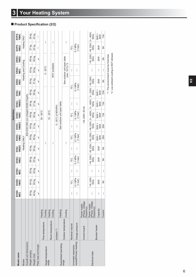
Your Heating System3EN
Hyd
robo
x
Mod
el n
ame
MEC
VM2C
MEC
VM2C
VM2E
CVM
6CVM
6EC
YM9C
YM9E
CTM
9CVM
2CM
ECVM
2CVM
2CYM
9CM
odes
Hea
ting
ON
LYH
eatin
g an
d C
oolin
gHe
atin
g O
NLY
Ove
rall
unit
dim
ensi
ons
800×
530×
360
mm
(Hei
ght×
Wid
th×D
epth
)W
eigh
t (em
pty)
38 k
g44
kg
42 k
g48
kg
43 k
g49
kg
44 k
g49
kg
44 k
g49
kg
45 k
g43
kg
49 k
g37
kg
38 k
gW
eigh
t (fu
ll)44
kg
50 k
g49
kg
55 k
g50
kg
56 k
g51
kg
56 k
g51
kg
56 k
g51
kg
50 k
g56
kg
42 k
g43
kg
Pla
te h
eat e
xcha
nger
——
Targ
et te
mpe
ratu
re
rang
e
Flow
tem
pera
ture
Hea
ting
25 -
60°C
Coo
ling
—5
- 25°
C—
Roo
m te
mpe
ratu
reH
eatin
g10
- 30
°CC
oolin
g—
NO
T av
aila
ble
—
Gua
rant
eed
oper
atin
g ra
nge
Am
bien
t *1
0 - 3
5°C
( 8
0%R
H)
Out
door
tem
pera
ture
Hea
ting
See
out
door
uni
t spe
c ta
ble.
Coo
ling
—S
ee o
utdo
or u
nit s
pec
tabl
e(m
in. 1
0°C
).*2
—
Unv
ente
d ex
pans
ion
ve
ssel
(Prim
ary
heat
ing)
Nom
inal
vol
ume
—10
L—
10 L
—10
L—
10 L
—10
L—
10 L
Cha
rge
pres
sure
—0.
1 M
Pa
(1 b
ar)
—0.
1 M
Pa
(1 b
ar)
—0.
1 M
Pa
(1 b
ar)
—0.
1 M
Pa
(1 b
ar)
—0.
1 M
Pa
(1 b
ar)
—0.
1 M
Pa
(1 b
ar)
Ele
ctric
al d
ata
Con
trol b
oard
Pow
er s
uppl
y (P
hase
, vol
tage
, fre
quen
cy)
~/N
, 230
V, 5
0 H
z
Boo
ster
hea
ter
Pow
er s
uppl
y (P
hase
, vol
tage
, fre
quen
cy)
—~/
N, 2
30V,
50
Hz
—~/
N, 2
30V,
50
Hz
~/N
, 230
V,
50H
z~/
N, 2
30V,
50
Hz
~/N
, 230
V,
50H
z3~
, 400
V,
50H
z3~
, 400
V,
50H
z3~
, 230
V,
50H
z~/
N, 2
30V,
50
Hz
—~/
N, 2
30V,
50
Hz
~/N
, 230
V,
50H
z3~
, 400
V,
50H
z
Cap
acity
—2k
W
—2k
W
2kW
2k
W +
4k
W2k
W +
4k
W3k
W +
6k
W3k
W +
6k
W3k
W +
6k
W2k
W—
2k
W2k
W3k
W +
6k
WC
urre
nt—
9A—
9A9A
26A
26A
13A
13A
23A
9A—
9A
9A13
A
*1 T
he e
nviro
nmen
t mus
t be
frost
-free
.
*2 L
ow a
mbi
ent c
oolin
g is
NO
T al
low
ed.
F1 F2 F3 F4
7
Customising Settings for Your Home4EN
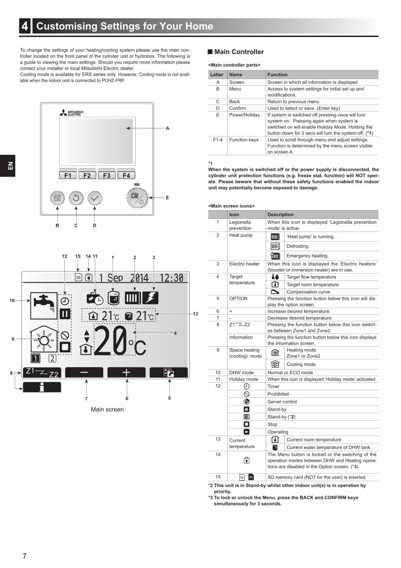
To change the settings of your heating/cooling system please use the main con-troller located on the front panel of the cylinder unit or hydrobox. The following is a guide to viewing the main settings. Should you require more information please contact your installer or local Mitsubishi Electric dealer.Cooling mode is available for ERS series only. However, Cooling mode is not avail-able when the indoor unit is connected to PUHZ-FRP.
Main Controller
B C D
E
A
12 11 1 32
10
94
7 6 5
15 14
13
8
<Main controller parts>
Letter Name FunctionA Screen Screen in which all information is displayedB Menu Access to system settings for initial set up and
C Back Return to previous menu.D Used to select or save. (Enter key)E Power/Holiday If system is switched off pressing once will turn
system on. Pressing again when system is switched on will enable Holiday Mode. Holding the button down for 3 secs will turn the system off. (*1)
F1-4 Function keys Used to scroll through menu and adjust settings. Function is determined by the menu screen visible on screen A.
*1
ate. Please beware that without these safety functions enabled the indoor unit may potentially become exposed to damage.
<Main screen icons>
Icon Description1 Legionella
preventionWhen this icon is displayed ‘Legionella prevention mode’ is active.
2 Heat pump ‘Heat pump’ is running.
Defrosting.
Emergency heating.
3 Electric heater When this icon is displayed the ‘Electric heaters’ (booster or immersion heater) are in use.
4 Target temperature Target room temperature
Compensation curve5 OPTION Pressing the function button below this icon will dis-
play the option screen.6 + Increase desired temperature.7 - Decrease desired temperature.8 Z1 Z2 Pressing the function button below this icon switch-
es between Zone1 and Zone2. Information Pressing the function button below this icon displays
the information screen. 9 Space heating
(cooling) modeHeating modeZone1 or Zone2
Cooling mode
10 DHW mode Normal or ECO mode11 Holiday mode When this icon is displayed ‘Holiday mode’ activated.12 Timer
ProhibitedServer controlStand-byStand-by (*2)StopOperating
13 Current temperature
Current room temperatureCurrent water temperature of DHW tank
14 The Menu button is locked or the switching of the operation modes between DHW and Heating opera-tions are disabled in the Option screen. (*3)
15 SD memory card (NOT for the user) is inserted.
priority.
simultaneously for 3 seconds.
Main screen
8
Customising Settings for Your Home4EN
Icon Description
Hot water (DHW)
Heating/Cooling
Schedule timer
Holiday mode
Initial settings
Service
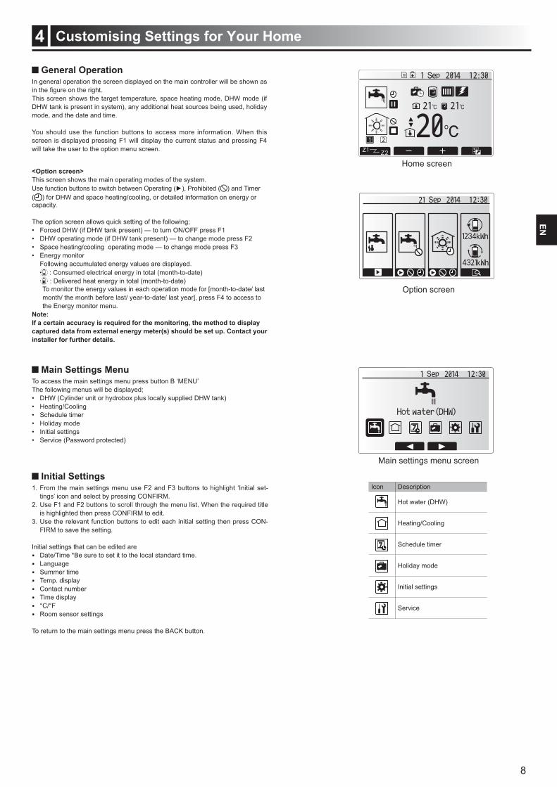
Home screen
Option screen
Main settings menu screen
General OperationIn general operation the screen displayed on the main controller will be shown as
This screen shows the target temperature, space heating mode, DHW mode (if DHW tank is present in system), any additional heat sources being used, holiday mode, and the date and time.
You should use the function buttons to access more information. When this screen is displayed pressing F1 will display the current status and pressing F4 will take the user to the option menu screen.
<Option screen>This screen shows the main operating modes of the system.
) and Timer ( ) for DHW and space heating/cooling, or detailed information on energy or capacity.
The option screen allows quick setting of the following;
Following accumulated energy values are displayed. : Consumed electrical energy in total (month-to-date) : Delivered heat energy in total (month-to-date)
To monitor the energy values in each operation mode for [month-to-date/ last month/ the month before last/ year-to-date/ last year], press F4 to access to the Energy monitor menu.
Note:
captured data from external energy meter(s) should be set up. Contact your installer for further details.
Main Settings MenuTo access the main settings menu press button B ‘MENU’The following menus will be displayed;
Initial Settings1. From the main settings menu use F2 and F3 buttons to highlight ‘Initial set-
tings’ icon and select by pressing CONFIRM.2. Use F1 and F2 buttons to scroll through the menu list. When the required title
is highlighted then press CONFIRM to edit.3. Use the relevant function buttons to edit each initial setting then press CON-
FIRM to save the setting.
Initial settings that can be edited are Date/Time *Be sure to set it to the local standard time. Language Summer time Temp. display Contact number Time display °C/°F Room sensor settings
To return to the main settings menu press the BACK button.
9
Customising Settings for Your Home4EN
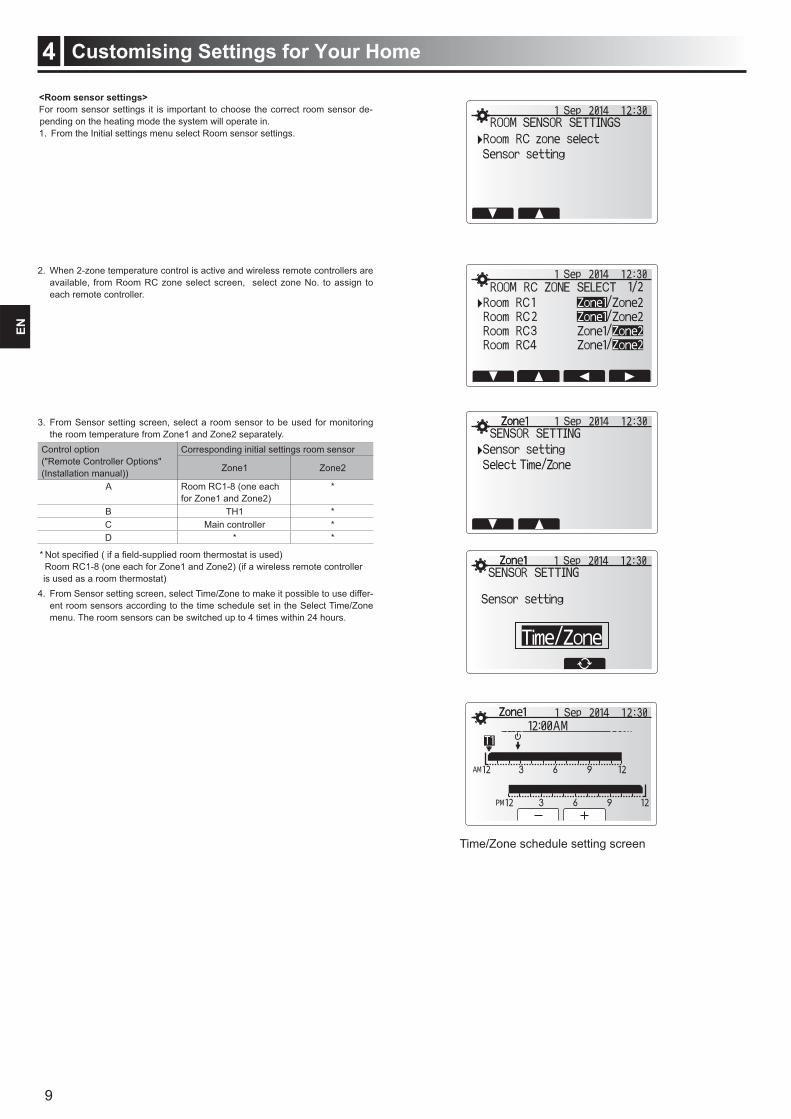
<Room sensor settings>For room sensor settings it is important to choose the correct room sensor de-pending on the heating mode the system will operate in. 1. From the Initial settings menu select Room sensor settings.
Time/Zone schedule setting screen
2. When 2-zone temperature control is active and wireless remote controllers are available, from Room RC zone select screen, select zone No. to assign to each remote controller.
3. From Sensor setting screen, select a room sensor to be used for monitoring the room temperature from Zone1 and Zone2 separately.
Control option ("Remote Controller Options" (Installation manual))
Corresponding initial settings room sensor
Zone1 Zone2
A Room RC1-8 (one each for Zone1 and Zone2)
*
B TH1 *C Main controller *D * *
Room RC1-8 (one each for Zone1 and Zone2) (if a wireless remote controller is used as a room thermostat)
4. From Sensor setting screen, select Time/Zone to make it possible to use differ-ent room sensors according to the time schedule set in the Select Time/Zone menu. The room sensors can be switched up to 4 times within 24 hours.
10
Customising Settings for Your Home4EN
DHW tank temp.
DHW max. temp.
DHW max. temp. drop
Start
DHW max. operation time
DHW mode restriction
DHW mode Time
Stop
Stop Restart
DHW max. temp.
DHW max. temp. drop
DHW tank temp.Stop
Start
Restart
Time
DHW mode DHW mode
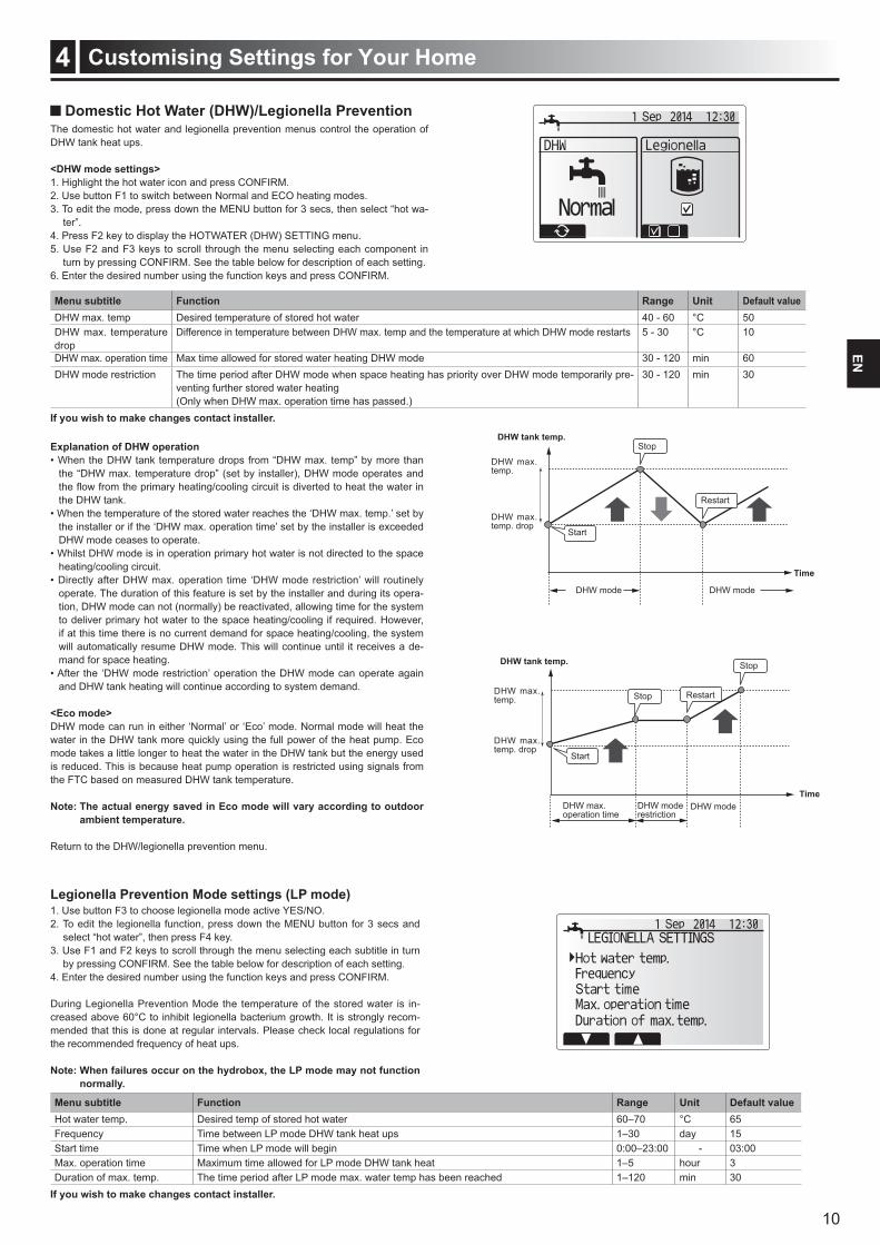
Domestic Hot Water (DHW)/Legionella PreventionThe domestic hot water and legionella prevention menus control the operation of DHW tank heat ups.
<DHW mode settings>1. Highlight the hot water icon and press CONFIRM.2. Use button F1 to switch between Normal and ECO heating modes.3. To edit the mode, press down the MENU button for 3 secs, then select “hot wa-
ter”.4. Press F2 key to display the HOTWATER (DHW) SETTING menu.5. Use F2 and F3 keys to scroll through the menu selecting each component in
turn by pressing CONFIRM. See the table below for description of each setting.6. Enter the desired number using the function keys and press CONFIRM.
Menu subtitle Function Range Unit Default valueDHW max. temp Desired temperature of stored hot water 40 - 60 °C 50DHW max. temperature drop
Difference in temperature between DHW max. temp and the temperature at which DHW mode restarts 5 - 30 °C 10
DHW max. operation time Max time allowed for stored water heating DHW mode 30 - 120 min 60DHW mode restriction The time period after DHW mode when space heating has priority over DHW mode temporarily pre-
venting further stored water heating(Only when DHW max. operation time has passed.)
30 - 120 min 30
If you wish to make changes contact installer.
Explanation of DHW operation
the “DHW max. temperature drop” (set by installer), DHW mode operates and
the DHW tank.
the installer or if the ‘DHW max. operation time’ set by the installer is exceeded DHW mode ceases to operate.
heating/cooling circuit.
operate. The duration of this feature is set by the installer and during its opera-tion, DHW mode can not (normally) be reactivated, allowing time for the system to deliver primary hot water to the space heating/cooling if required. However, if at this time there is no current demand for space heating/cooling, the system will automatically resume DHW mode. This will continue until it receives a de-mand for space heating.
and DHW tank heating will continue according to system demand.
<Eco mode>DHW mode can run in either ‘Normal’ or ‘Eco’ mode. Normal mode will heat the water in the DHW tank more quickly using the full power of the heat pump. Eco mode takes a little longer to heat the water in the DHW tank but the energy used is reduced. This is because heat pump operation is restricted using signals from the FTC based on measured DHW tank temperature.
Note: The actual energy saved in Eco mode will vary according to outdoor ambient temperature.
Return to the DHW/legionella prevention menu.
Legionella Prevention Mode settings (LP mode)1. Use button F3 to choose legionella mode active YES/NO. 2. To edit the legionella function, press down the MENU button for 3 secs and
select “hot water”, then press F4 key.3. Use F1 and F2 keys to scroll through the menu selecting each subtitle in turn
by pressing CONFIRM. See the table below for description of each setting.4. Enter the desired number using the function keys and press CONFIRM.
During Legionella Prevention Mode the temperature of the stored water is in-creased above 60°C to inhibit legionella bacterium growth. It is strongly recom-mended that this is done at regular intervals. Please check local regulations for the recommended frequency of heat ups.
normally.
Menu subtitle Function Range Unit Default valueHot water temp. Desired temp of stored hot water 60–70 °C 65Frequency Time between LP mode DHW tank heat ups 1–30 day 15Start time Time when LP mode will begin 0:00–23:00 - 03:00Max. operation time Maximum time allowed for LP mode DHW tank heat 1–5 hour 3Duration of max. temp. The time period after LP mode max. water temp has been reached 1–120 min 30
If you wish to make changes contact installer.
11
Customising Settings for Your Home4EN
DHW tank temp.Stop
Restart
Stop
Time
Start
Stop temp.Legionella hot water temp.
LP mode LP mode
Restart temp.
Space heating/cooling
Duration of Max. temp.
Mode
(LP mode: Legionella Prevention mode)
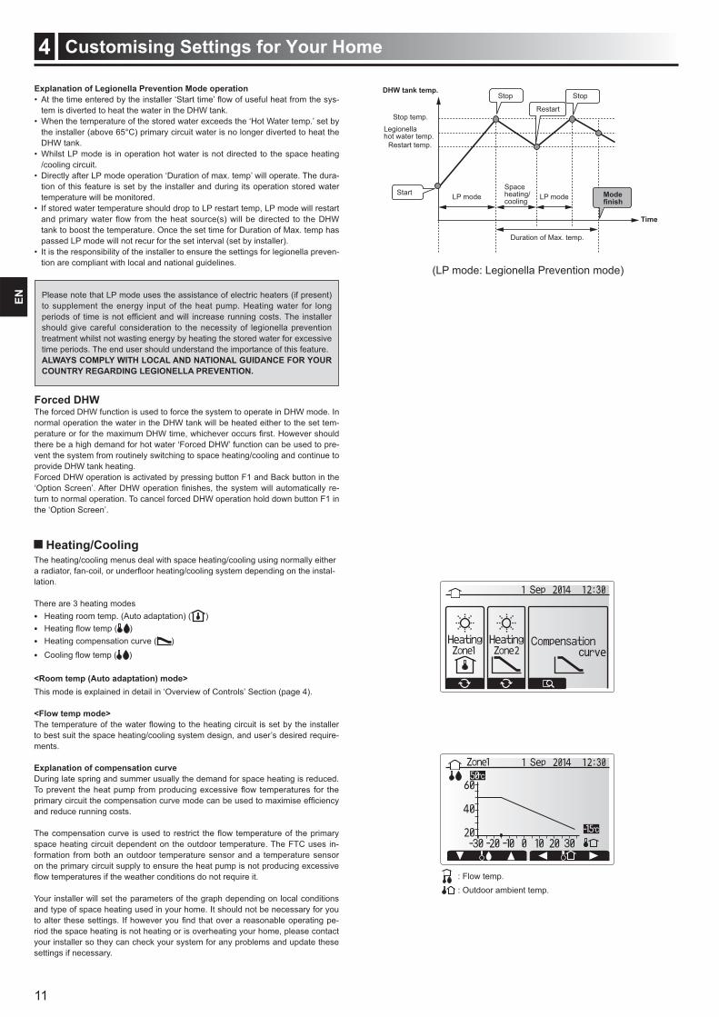
Heating/CoolingThe heating/cooling menus deal with space heating/cooling using normally either
-lation.
There are 3 heating modes Heating room temp. (Auto adaptation) ( )
( ) Heating compensation curve ( ) Cooling ( )
<Room temp (Auto adaptation) mode>This mode is explained in detail in ‘Overview of Controls’ Section (page 4).
<Flow temp mode>
to best suit the space heating/cooling system design, and user’s desired require-ments.
Explanation of compensation curveDuring late spring and summer usually the demand for space heating is reduced.
and reduce running costs.
space heating circuit dependent on the outdoor temperature. The FTC uses in-formation from both an outdoor temperature sensor and a temperature sensor on the primary circuit supply to ensure the heat pump is not producing excessive
Your installer will set the parameters of the graph depending on local conditions and type of space heating used in your home. It should not be necessary for you
-riod the space heating is not heating or is overheating your home, please contact your installer so they can check your system for any problems and update these settings if necessary.
Explanation of Legionella Prevention Mode operation-
tem is diverted to heat the water in the DHW tank.
the installer (above 65°C) primary circuit water is no longer diverted to heat the DHW tank.
/cooling circuit.-
tion of this feature is set by the installer and during its operation stored water temperature will be monitored.
and primary water flow from the heat source(s) will be directed to the DHW tank to boost the temperature. Once the set time for Duration of Max. temp has passed LP mode will not recur for the set interval (set by installer).
-tion are compliant with local and national guidelines.
Please note that LP mode uses the assistance of electric heaters (if present) to supplement the energy input of the heat pump. Heating water for long
should give careful consideration to the necessity of legionella prevention treatment whilst not wasting energy by heating the stored water for excessive time periods. The end user should understand the importance of this feature.ALWAYS COMPLY WITH LOCAL AND NATIONAL GUIDANCE FOR YOUR COUNTRY REGARDING LEGIONELLA PREVENTION.
Forced DHWThe forced DHW function is used to force the system to operate in DHW mode. In normal operation the water in the DHW tank will be heated either to the set tem-
there be a high demand for hot water ‘Forced DHW’ function can be used to pre-vent the system from routinely switching to space heating/cooling and continue to provide DHW tank heating. Forced DHW operation is activated by pressing button F1 and Back button in the
-turn to normal operation. To cancel forced DHW operation hold down button F1 in the ‘Option Screen’.
: Flow temp. : Outdoor ambient temp.
12
Customising Settings for Your Home4EN
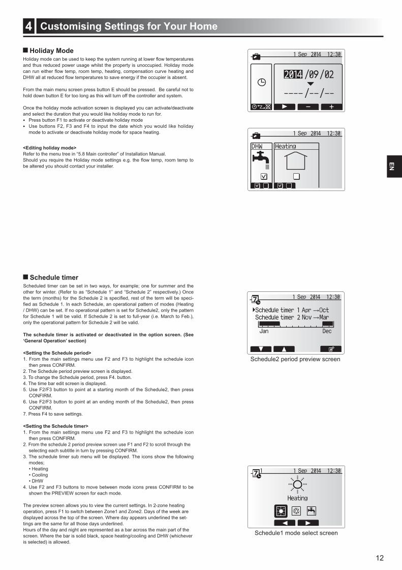
Holiday Mode
and thus reduced power usage whilst the property is unoccupied. Holiday mode
From the main menu screen press button E should be pressed. Be careful not to hold down button E for too long as this will turn off the controller and system.
Once the holiday mode activation screen is displayed you can activate/deactivate and select the duration that you would like holiday mode to run for. Press button F1 to activate or deactivate holiday mode Use buttons F2, F3 and F4 to input the date which you would like holiday
mode to activate or deactivate holiday mode for space heating.
<Editing holiday mode> Refer to the menu tree in “5.8 Main controller” of Installation Manual.
be altered you should contact your installer.
Schedule timerScheduled timer can be set in two ways, for example; one for summer and the other for winter. (Refer to as “Schedule 1” and “Schedule 2” respectively.) Once
-
/ DHW) can be set. If no operational pattern is set for Schedule2, only the pattern for Schedule 1 will be valid. If Schedule 2 is set to full-year (i.e. March to Feb.), only the operational pattern for Schedule 2 will be valid.
The schedule timer is activated or deactivated in the option screen. (See ‘General Operation’ section)
<Setting the Schedule period>1. From the main settings menu use F2 and F3 to highlight the schedule icon
then press CONFIRM.2. The Schedule period preview screen is displayed.3. To change the Schedule period, press F4. button.4. The time bar edit screen is displayed.5. Use F2/F3 button to point at a starting month of the Schedule2, then press
CONFIRM.6. Use F2/F3 button to point at an ending month of the Schedule2, then press
CONFIRM.7. Press F4 to save settings.
<Setting the Schedule timer>1. From the main settings menu use F2 and F3 to highlight the schedule icon
then press CONFIRM.2. From the schedule 2 period preview screen use F1 and F2 to scroll through the
selecting each subtitle in turn by pressing CONFIRM.3. The schedule timer sub menu will be displayed. The icons show the following
modes;
4. Use F2 and F3 buttons to move between mode icons press CONFIRM to be shown the PREVIEW screen for each mode.
The preview screen allows you to view the current settings. In 2-zone heating operation, press F1 to switch between Zone1 and Zone2. Days of the week are displayed across the top of the screen. Where day appears underlined the set-tings are the same for all those days underlined.Hours of the day and night are represented as a bar across the main part of the screen. Where the bar is solid black, space heating/cooling and DHW (whichever is selected) is allowed.
Schedule1 mode select screen
Schedule2 period preview screen
13
Customising Settings for Your Home4EN
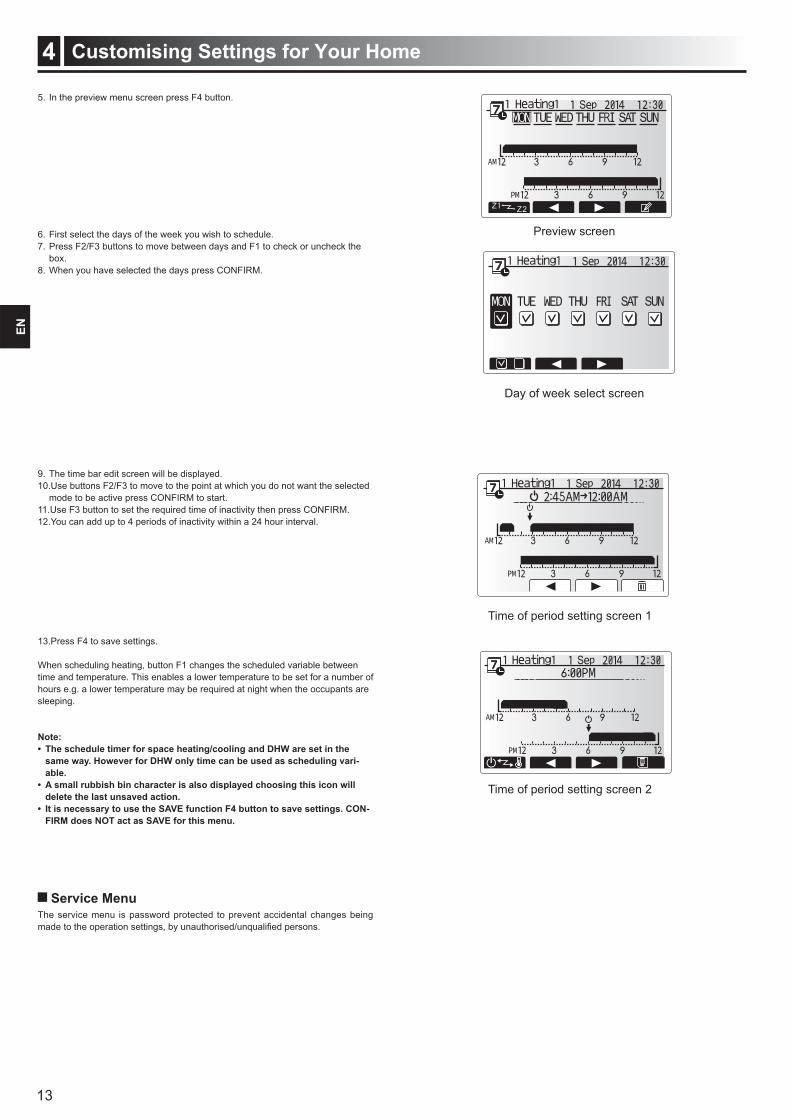
Preview screen
Day of week select screen
Service MenuThe service menu is password protected to prevent accidental changes being
Time of period setting screen 1
Time of period setting screen 2
5. In the preview menu screen press F4 button.
6. First select the days of the week you wish to schedule.7. Press F2/F3 buttons to move between days and F1 to check or uncheck the
box.8. When you have selected the days press CONFIRM.
9. The time bar edit screen will be displayed.10.Use buttons F2/F3 to move to the point at which you do not want the selected
mode to be active press CONFIRM to start.11.Use F3 button to set the required time of inactivity then press CONFIRM.12.You can add up to 4 periods of inactivity within a 24 hour interval.
13.Press F4 to save settings.
When scheduling heating, button F1 changes the scheduled variable between time and temperature. This enables a lower temperature to be set for a number of hours e.g. a lower temperature may be required at night when the occupants are sleeping.
Note:
same way. However for DHW only time can be used as scheduling variable.
delete the last unsaved action.
FIRM does NOT act as SAVE for this menu.
14
Service and Maintenance5EN
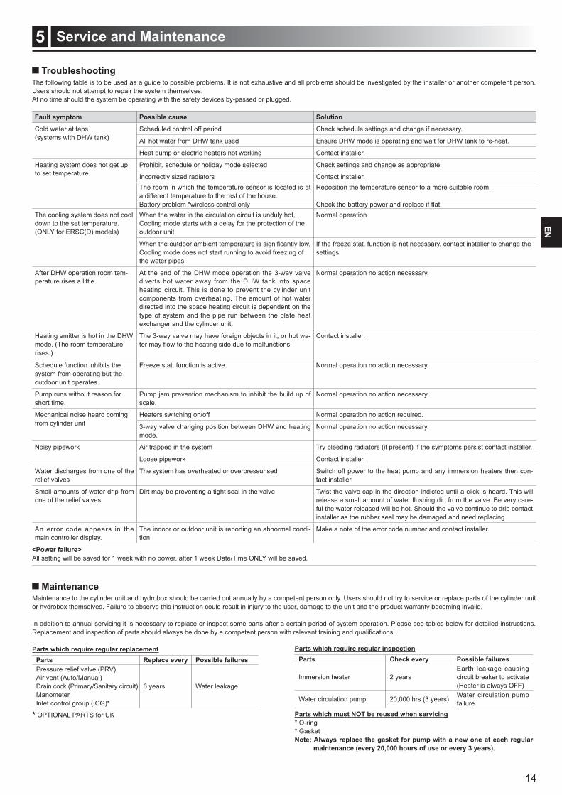
TroubleshootingThe following table is to be used as a guide to possible problems. It is not exhaustive and all problems should be investigated by the installer or another competent person. Users should not attempt to repair the system themselves. At no time should the system be operating with the safety devices by-passed or plugged.
Fault symptom Possible cause Solution
Cold water at taps (systems with DHW tank)
Scheduled control off period Check schedule settings and change if necessary.
All hot water from DHW tank used Ensure DHW mode is operating and wait for DHW tank to re-heat.
Heat pump or electric heaters not working Contact installer.
Heating system does not get up to set temperature.
Prohibit, schedule or holiday mode selected Check settings and change as appropriate.
Incorrectly sized radiators Contact installer.The room in which the temperature sensor is located is at a different temperature to the rest of the house.
Reposition the temperature sensor to a more suitable room.
Battery problem *wireless control onlyThe cooling system does not cool down to the set temperature. (ONLY for ERSC(D) models)
When the water in the circulation circuit is unduly hot, Cooling mode starts with a delay for the protection of the outdoor unit.
Normal operation
Cooling mode does not start running to avoid freezing of the water pipes.
If the freeze stat. function is not necessary, contact installer to change the settings.
After DHW operation room tem-perature rises a little.
At the end of the DHW mode operation the 3-way valve diverts hot water away from the DHW tank into space heating circuit. This is done to prevent the cylinder unit components from overheating. The amount of hot water directed into the space heating circuit is dependent on the type of system and the pipe run between the plate heat exchanger and the cylinder unit.
Normal operation no action necessary.
Heating emitter is hot in the DHW mode. (The room temperature rises.)
The 3-way valve may have foreign objects in it, or hot wa- Contact installer.
Schedule function inhibits the system from operating but the outdoor unit operates.
Freeze stat. function is active. Normal operation no action necessary.
Pump runs without reason for short time.
Pump jam prevention mechanism to inhibit the build up of scale.
Normal operation no action necessary.
Mechanical noise heard coming from cylinder unit
Heaters switching on/off Normal operation no action required.
3-way valve changing position between DHW and heating mode.
Normal operation no action necessary.
Noisy pipework Air trapped in the system Try bleeding radiators (if present) If the symptoms persist contact installer.
Loose pipework Contact installer.
Water discharges from one of the relief valves
The system has overheated or overpressurised Switch off power to the heat pump and any immersion heaters then con-tact installer.
Small amounts of water drip from one of the relief valves.
Dirt may be preventing a tight seal in the valve Twist the valve cap in the direction indicted until a click is heard. This will -
ful the water released will be hot. Should the valve continue to drip contact installer as the rubber seal may be damaged and need replacing.
An error code appears in the main controller display.
The indoor or outdoor unit is reporting an abnormal condi-tion
Make a note of the error code number and contact installer.
<Power failure>All setting will be saved for 1 week with no power, after 1 week Date/Time ONLY will be saved.
Maintenance Maintenance to the cylinder unit and hydrobox should be carried out annually by a competent person only. Users should not try to service or replace parts of the cylinder unit or hydrobox themselves. Failure to observe this instruction could result in injury to the user, damage to the unit and the product warranty becoming invalid.
In addition to annual servicing it is necessary to replace or inspect some parts after a certain period of system operation. Please see tables below for detailed instructions.
Parts Replace every Possible failuresPressure relief valve (PRV)Air vent (Auto/Manual)Drain cock (Primary/Sanitary circuit)ManometerInlet control group (ICG)*
6 years Water leakage
* OPTIONAL PARTS for UK
Parts Check every Possible failures
Immersion heater 2 years Earth leakage causing circuit breaker to activate (Heater is always OFF)
Water circulation pump 20,000 hrs (3 years) Water circulation pump failure
Parts which must NOT be reused when servicing* O-ring* GasketNote: Always replace the gasket for pump with a new one at each regular

HEAD OFFICE: TOKYO BLDG., 2-7-3, MARUNOUCHI, CHIYODA-KU, TOKYO 100-8310, JAPANAuthorized representative in EU: MITSUBISHI ELECTRIC EUROPE B.V. HARMAN HOUSE, 1 GEORGE STREET, UXBRIDGE, MIDDLESEX UB8 1QQ, U.K.This product is made by Mitsubishi Electric Air Conditioning Systems Europe Ltd.: NETTLEHILL Rd, HOUSTOUN IND ESTATE,
LIVINGSTON, EH54 5EQ, UK
RG79D942H01 Printed in the UNITED KINGDOM
Installers: Please be sure to put your contact address/telephone number on
this manual before handing it to the customer.
Recommended