Embed Size (px)
Citation preview
CYLINDER BY CYLINDER ENGINE MODELING OF SINGLE CYLINDER 4
STROKE ENGINE FOR CONTROL SYSTEM DEVELOPMENT
HASFAZRI BIN ABDUL RAHMAN
Report submitted in partial fulfillment of the requirements for the award of
Bachelor of Mechanical with Automotive Engineering
Faculty of Mechanical Engineering
UNIVERSITI MALAYSIA PAHANG
JUNE 2012
vi
ABSTRACT
The objective of this thesis is to design and simulate cylinder by cylinder engine
model for control oriented study based on single cylinder four stroke engines, which
combines both physical formulae, such as engine geometries, and empirical formulae.
The engine performance, torque and power is calculated by integrating the pressure
inside cylinder within one engine cycle. The importance of this study is to predict the
engine performance parameters such as indicated work, brake power, and torque that
provided with air fuel ratio data and detail geometrical specifications. The model of
FZ150i full engine specifications is used for simulation in order to predict the engine
performance. The model is simulated between 2000 to 6000 rpm of engine speed range.
From this simulation, the result shows that it is almost same with the experimental data
by Sitthiracha (2006). Without build the real engine, all the engine performance
parameter can be calculated from this simulation, and reduced the time and cost.

vii
ABSTRAK
Objektif tesis ini adalah untuk mereka bentuk dan simulasi silinder dengan
menggunakan model enjin silinder bagi kajian kawalan yang berdasarkan enjin empat
strok dimana ia mengabungkan kedua-dua formula fizikal, seperti geometrik enjin dan
formula empirik. Prestasi enjin, tork dan kuasa boleh dihitung dengan mengintegrasikan
tekanan dalam silinder bagi tempoh satu kitaran enjin. Kepentingan kajian ini ialah
untuk meramal prestasi parameter enjin seperti kerja tertunjuk, kuasa brek dan tork
dengan menggunakan data nisbah bahan api udara dan spesifikasi geometrik yang lebih
terperinci. Spesifikasi enjin penuh Model FZ150i digunakan dalam simulasi supaya
dapat meramal prestasi enjin. Model disimulasikan dengan kelajuan enjin pada kelajuan
2000 hingga 6000 rpm. Hasil keputusan simulasi ini menunjukkan ianya hampir sama
dengan data eksperimen oleh Sitthiracha (2006). Tanpa membina enjin yang sebenar,
kesemua prestasi parameter enjin boleh dihitung daripada program simulasi ini dimana
ianya dapat menjimatkan masa dan kos.
ix
TABLE OF CONTENT
ITEMS TITLE PAGE
SUPERVISOR’S DECLARATION ix
STUDENT’S DECLARATION ix
ABSTRACT ix
ABSTRAK ix
ACKNOWLEDGEMENTS ix
TABLE OF CONTENTS ix
LIST OF TABLES ix
LIST OF FIGURES ix
LIST OF SYMBOLS ix
LIST OF ABBREVIATIONS ix
CHAPTER 1 INTRODUCTION 1
1.0 Project title 1
1.1 Project Background 1
1.2 Problem Statement 2
1.3 Objectives 2
1.4 Scopes of Study 2
1.5 Flow Charts of Study 3
1.6 Summary 4
CHAPTER 2 LITERATURE REVIEW 5
2.0 Introduction 5
2.1 Internal Combustion Engine principle operation 6
2.1.1 Spark Ignition Engine 6

x
2.1.1 Basic of Four Stroke Engine System 7
2.3 Control Oriented Modelling
2.3.1 Physical sub-model
2.3.2 Mean Value Engine Modelling(MVEM)
2.3.3 Cylinder to Cylinder Engine Model (CCEM)
2.3.4 Comparison between (MVEM) and (CCEM)
10
10
12
13
14
2.4 Cylinder to Cylinder Model
2.4.1 Intake dynamic
2.4.2 Torque dynamic
2.4.3 Exhaust dynamic
14
15
16
17
2.5 Summary 17
CHAPTER 3 METHODOLOGY 18
3.0 Introduction
3.1 Flow Chart for Final Year Project
18
19
3.2 Engine modelling using SIMULINK
3.2.1 Main engine modelling
3.2.2 Engine model block details
20
21
22
3.3 Throttle model-valve 35
3.4 Crank-slider model 36
3.5 Exhaust model-valve 37
3.6 Parameter of study 38
3.7 Model building setup 38
3.8 Baseline engine specifications
3.8.1 Case setup
38
39
3.9 Summary 39
xi
CHAPTER 4 RESULT AND DISSCUSION 40
4.0 Introduction
40
4.1 Result data and graph 41
4.1.1 Result of Brake Power
4.1.2 Result of Torque
4.1.3 Trend comparison graph of brake power and torque
4.1.4 Result of Thermal Efficiency
4.1.5 Graph for comparison of Thermal Efficiency
4.1.6 Result of Indicated Work
4.1.7 Result of Temperature
41
42
43
44
45
46
47
4.2 Summary
48
CHAPTER 5 CONCLUSION AND RECOMMENDATION 49
5.1 Conclusion 49
5.2 Recommendation 50
REFFERENCES
51
APPENDIX A1 Gantt chart Final Year Project 1
APPENDIX A2 Gantt chart Final Year Project 2
APPENDIX B Data result
53
54
55

xii
LIST OF TABLES
TABLE TITLE PAGE
3.1 Yamaha FZ150i engine details 38
3.2 Simulation case setups 39
4.1 Tabulated data for Brake Power 41
4.2 Tabulated data for Torque 42
4.3 Tabulated data for Thermal Efficiency 44
4.4 Tabulated data for Indicated Work 46
4.5 Tabulated data for Temperature 47
xiii
LIST OF FIGURES
FIGURE TITLE PAGE
1.0 Project Process Flowchart of Final Year Project 1 3
2.1 Schematic of Spark Ignition Engine 6
2.2 Four Stroke Engine System 7
2.3 Pressure Volume Diagram of Otto Cycle 8
3.1 Flow chart of overall Final Year Project 19
3.2 Main Model Block Diagram 21
3.3 Cm block details 22
3.4 Engine geometry block details 22
3.5 Engine geometry/A(CA) block details 23
3.6 Engine geometry/V(CA), Vc block details 23
3.7 Engine geometry/Vd block details 24
3.8 Engine geometry/Crank Geometry block details 24
3.9 Residual mass block details 25
3.10 T block details 25
3.11 Heat Transfer block details 26
3.12 Burn duration block details 26
3.13 h block details 27
3.14 Weibe fn block details 27
3.15 P block 28
3.16 P/Pratio block details 29
3.17 P/Lv block details 29
3.18 P/Cd block details 30
3.19 P/mdot block details 31
3.20 P/Cheat factor block details 32
3.21 P/Cf factor block details 32
3.22 Mw block details 32
3.23 Work & Power block details 33
xiv
3.24 Work & Power/Work block details 33
3.25 Work & Power/FMEP block details 34
3.26 Work & Power/Effective power block details 34
3.27 Piston cylinder and geometries 35
4.1 Brake Power versus Engine speed 41
4.2 Torque versus Engine speed 42
4.3 Brake Power and Torque Simulation from Sitthiracha,
(2006)
43
4.4 Thermal Efficiency versus Engine speed 44
4.5 Thermal Efficiency by Sitthiracha, (2006) 45
4.6 Indicated Work versus Engine speed 46
4.7 Temperature versus Engine speed 47
xv
LIST OF SYMBOL
a Crank Radius
A Exposed Combustion Chamber Surface Area
AR Reference Area
b Cylinder Bore
CD Discharge Coefficient
Cf Frictional Loss Factor
Cheat Charge Heating Factor
Cm Mean Piston Speed
Div Inlet Valve Diameter
Dv Valve Diameter
f Fraction of Heat Added
h Convection Heat Transfer Coefficient
HV Heating Value of Fuel
IVC Inlet Valve Close Angle After BDC
IVO Inlet Valve Open angle Before TDC
k Specific Heat Ratio
l Connecting Rod Length
Liv,max Maximum Inlet Valve Lift
Lv Valve Lift Function
mair,stoich Theoretical Amount of Air Requirement
m Mass Flow Rate
ma Air Mass
N Engine Speed
P Pressure Inside Cylinder
xvi
Pe Effective Power
Qin Overall Heat Input
Q Heat Addition
Qloss Heat Transfer
R Gas Constant
s Stroke
Tg Temperature of Cylinder Gas
Texh Exhaust Gas Temperature
Tw Cylinder Wall Temperature
pf Friction Mean Effective Pressure
pme Brake Mean Effective Pressure
T0 Stagnation Temperature
V Cylinder Volume
Vd Displacement Volume
Δθ Duration of Heat Addition
ε Compression Ratio
ηv Thermal Efficiency
θ Crank Angle
θ0 Angle of Start of Heat Addition
ρa Air Density

xvii
LIST OF ABBREVIATION
SYMBOL
SPECIFICATION
BDC Bottom Dead Center
MVEM Mean Value Engine Model
CCEM Cylinder-by-cylinder Engine Model
EGR Exhaust Gas Recirculation
TDC Top Dead Center
WOT Wide Open Throttle
HC Hydrocarbon
rpm Round per Minute
CO Carbon Monoxide

xviii
LIST OF APPENDICES
APPENDICES TITLE PAGE
A1 Gantt chart for Final Year Project 1 52
A2 Gantt chart for Final Year Project 2 53
B Table of Data Result 54
CHAPTER 1
INTRODUCTION
1.0 PROJECT TITLE
Cylinder by Cylinder Engine Modeling of Single Cylinder 4 Stroke Engine For
Control System Development.
1.1 PROJECT BACKGROUND
The cylinder by cylinder engine model (CCEM) is a mathematical model
derived from basic physical principles such as conservation of mass and energy
equations. CCEM can predict an engine’s main external variables such as crankshaft
speed and manifold pressure, and important internal variables, such as volumetric and
thermal efficiencies.
The model consists of three main components: the throttle model, exhaust
model, and crank-slider model. Adjusting the parameters allow the model to be used for
new engines of interest. The importance of this study is to predict the engine
performance parameters such as indicated work, brake power, and torque that provided
with air fuel ratio data and detail geometrical specifications.
The method that has been chosen for this project is using simulation to predict
the engine performance parameters. This is because this method can save time and
reduce the spending of money to build engine test-rig for experimental work.
2
1.2 PROBLEM STATEMENT
In order to develop a new electronic control system for an engine, a control
oriented model need to be proposed to assist the initial design and development work.
The control oriented model shall be based on cylinder-to-cylinder approach which
include the throttle body, exhaust and crank-slider model.
1.3 PROJECT OBJECTIVES
The objective of this study is to design and simulate cylinder by cylinder engine
model for control oriented study based on single cylinder four stroke engines.
1.4 PROJECT SCOPE
Basically, this analysis based on:
1. The model is based on single cylinder four strokes SI Engine.
2. The model consisted of dynamics model of air-flow, fuel-flow and
crankshaft dynamics.
3. The model is limited to physical/geometrical representation of the engine
only. The fuel injection with it associated controller is not part of current
scope.
4. The model used to predict engine performance parameters such as
indicated power, brake power, torque and provided with air fuel ratio
data and detail geometrical specifications.
5. The model used to simulate engine operating range from idle speed
condition until achievable maximum speed and load.
3
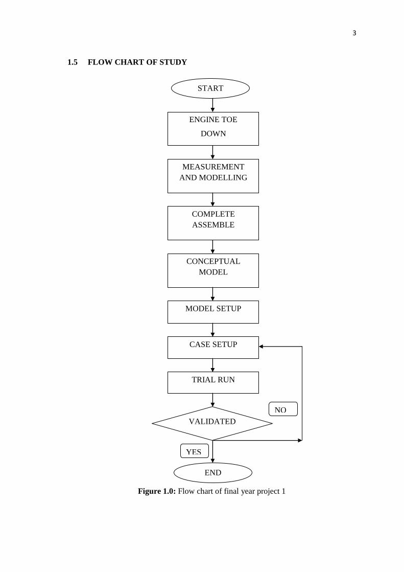
1.5 FLOW CHART OF STUDY
Figure 1.0: Flow chart of final year project 1
START
ENGINE TOE
DOWN
MEASUREMENT
AND MODELLING
COMPLETE
ASSEMBLE
CONCEPTUAL
MODEL
TRIAL RUN
CASE SETUP
MODEL SETUP
END
YES
NO
VALIDATED
4
1.6 SUMMARY
The CCEM is a mathematical model derived from basic physical principles such
as conservation of mass and energy equations. The importance of this study is to predict
the engine performance parameters such as indicated work, brake power, and torque.
The model is provided with air fuel ratio data and detail geometrical specifications to
perform the simulation.
CHAPTER 2
LITERATURE REVIEW
2.0 INTRODUCTION
In this chapter, introductions about cylinder by cylinder engine modeling for
control system development of a single cylinder-four-stroke engine is discussed. It is
used mainly for design and simulating the system of engine without spending much
time on experimental bench. From that the engine parameters from the output such as
torque, brake power, and indicated work can be determined. A CCEM is describing
each cylinder individually, could prove a useful and also needed to model cylinder
individual phenomena such as misfire when developing systems for diagnostics. This
simulation method allows the engine designed to test different parameters without
building real parts or even real engines.

6
2.1 INTERNAL COMBUSTION ENGINE PRINCIPLE OPERATION
2.1.1 Spark Ignition Engine
The spark ignition engine is used in variety application such as cars, motorcycle,
small engine generator and etc.
Figure 2.1: Schematic of spark ignition engine
Source: Stephen (2006)
Where:
E - Exhaust camshaft
I - Intake camshaft
S - Spark plug
V - Valves
P - Piston
R - Connecting rod
C - Crankshaft
W - Water jackets
E
W
S I
V
P
R
C
7
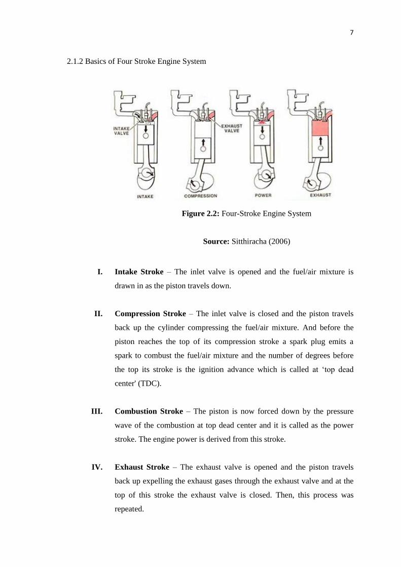
2.1.2 Basics of Four Stroke Engine System
Figure 2.2: Four-Stroke Engine System
Source: Sitthiracha (2006)
I. Intake Stroke – The inlet valve is opened and the fuel/air mixture is
drawn in as the piston travels down.
II. Compression Stroke – The inlet valve is closed and the piston travels
back up the cylinder compressing the fuel/air mixture. And before the
piston reaches the top of its compression stroke a spark plug emits a
spark to combust the fuel/air mixture and the number of degrees before
the top its stroke is the ignition advance which is called at ‘top dead
center' (TDC).
III. Combustion Stroke – The piston is now forced down by the pressure
wave of the combustion at top dead center and it is called as the power
stroke. The engine power is derived from this stroke.
IV. Exhaust Stroke – The exhaust valve is opened and the piston travels
back up expelling the exhaust gases through the exhaust valve and at the
top of this stroke the exhaust valve is closed. Then, this process was
repeated.

8
The above is the cycle of operation of one cylinder of a 4-stroke engine which
has two or more cylinders acting in concert with each other to produce the engine
power. It is interesting to note that one complete engine cycle takes two revolutions but
that individual valves and spark plugs only operate once in this time when their timing
needs to be taken from a half engine speed signal, or we call it as the camshafts speed.
With models for each of these processes, the simulation of complete engine
cycle can be built up and be analyzed to provide information on engine performances.
These ideal models that describe characteristic of each process are proposed. However
the calculation needs information from each state as shown in Fig.2.3a and Fig.2.3b.
(a) (b)
Figure 2.3: Pressure-volume diagram of Otto cycle:
(a) Ideal, (b) real
Source: Zeng et. al,(2004)
Overall engine work can be determined by integrating the area under the
pressure-volume diagram and there are so many previous works concerned mainly
prediction the pressure inside the combustion chamber (Zeng et. al, 2004). But the
pressure and volume are influenced by engine geometries during variation of crank
angle. Then the pressure and displacement volume are needed to convert as functions of
crank angle. Then Kirkpatrick et. al (2005) proposed the method that can calculate the
pressure and volume at any crank angle. And the combustion process can be described
by the simple correlation, (Heywood, 1988).

9
The results from Zeng et. al (2004), indicated that heat transfer from inside the
cylinder to engine cooling water had much influences on the pressure inside the cylinder
and the heat transfer function is needed to take into account in the model.
Many researchers reported that the mass of mixture that flows into the cylinder
during intake stroke is a very importance parameter (Andersson, 2002), by Heywood,
(1988), because it affects amount of fuel which mixes with the air. By combining the
ideal gas law and volumetric efficiency, this mass can be determined and it is very
difficult to evaluate because they are affected by many factors, and for examples the
manifold geometries and valve timing, (Heywood, 1988). So Kuo et. al (1996) assumed
that the pressure inside manifold and inside the cylinder is the same value, and the effect
of volumetric efficiency can be neglected. But Kuo (1996), used corrective equation
from real experiment to compensate the errors. While Zeng and Assanis (2004), took
the effect of volumetric efficiency into account.
However the data were obtained from the real experiment and stored in a 3-
dimension table by relation between engine speed and intake manifold pressure. The
combining of those methods that are mentioned above can predict the engine
performances precisely if some testing data are known, mainly the volumetric
efficiency.
10
2.2 CONTROL ORIENTED MODELING
There are numerous ways of describing reality through a model (Ramstedt and
Silverlind, 2001). Some are more complex than others and the different approaches may
differ in both structure and accuracy.
From previous study, a model of a four-cylinder spark ignition engine and
capability to model an internal combustion engine from the throttle to the crankshaft
output by Crossley and Cook (1991). It is used well-defined physical principles
supplemented, where appropriate, with empirical relationships that describe the system's
dynamic behavior without introducing unnecessary complexity, and it have some
relation with this study.
2.2.1 Physical sub-model
This example describes the concepts and details surrounding the creation of
engine models with emphasis on important control oriented modeling techniques. The
basic model uses the enhanced capabilities of control oriented modeling to capture time-
based events with high accuracy. During this simulation, a triggered subsystem models
the transfer of the air-fuel mixture from the intake manifold to the cylinders via discrete
valve events. The places takes the concurrently with the continuous-time processes of
intake flow, torque generation and acceleration.
The second model adds an additional triggered subsystem that provides closed-
loop engine speed control via a throttle actuator. This model can be used as standalone
engine simulations and also can be used within a larger system model, such as an
integrated vehicle and power train simulation in the development of a traction control
system. This model is based on published results by Sitthiracha (2006). It describes the
simulation of a four-cylinder spark ignition internal combustion engine. They work also
shows how a simulation based on this model was validated against dynamometer test
data. The following sections are analyzing the key elements of the engine model that
were identified by them:
11
I. Throttle
II. Intake manifold
III. Mass flow rate
IV. Compression stroke
V. Torque generation and acceleration
I. Throttle
The first element of the model is the throttle body. The control input is the angle
of the throttle plate. The rate at which the model introduces air into the intake manifold
can be expressed as the product of two functions which is an empirical function of the
throttle plate angle only and as the function of the atmospheric and manifold pressures.
And in cases of lower manifold pressure (high pressure), the flow rate that is through
the throttle body is sonic and is only as a function of the throttle angle. This model
accounts for this low pressure behavior with a switching condition in the
compressibility equations shown in Equation 1.
II. Intake Manifold
The simulation models the intake manifold as a differential equation for the
manifold pressure. The difference in the incoming and outgoing mass flow rates
represents the net rate of change of air mass with respect to time. This quantity,
according to the ideal gas law, is proportional to the time derivative of the manifold
pressure. Note that, unlike the model of Crossley and Cook (1991), although this can
easily be added, this model doesn't incorporate exhaust gas recirculation (EGR).
III. Intake Mass Flow Rate
The mass flow rate is a function of the manifold pressure and the engine speed
in order to determine the total air charge pumped into the cylinders, simulation
integrates the mass flow rate from the intake manifold and samples it at the end of each
intake stroke process. This is determines the total air mass that is present in each
cylinder after the intake stroke and before compression.