CARPCO MODEL MIH(13)111-5 LABORATORY
HIGH-INTENSITY INDUCED-ROLL MAGNETIC SEPARATOR
Revision: 03-2
SERIAL NUMBER
221-06
University Of Vermont
USA
June 2006
OUTOKUMPU TECHNOLOGY, INC. Physical Separation Division
6100 Phillips HighwayJacksonville, Florida U.S.A. 32216 telephone (904)353-3681 fax (904)353-8705
OUTOKUMPU TECHNOLOGY, INC. Physical Separation Division Operating Manual MIH(13)111-5
Revision 03-2 Page i
TABLE OF CONTENTS 1.0 SAFETY WARNINGS.................................................................................... 2 2.0 INSTALLATION.............................................................................................. 4
2.1 Drawings.............................................................................................. 4 2.2 General ................................................................................................ 4 2.3 Electrical Connections ......................................................................... 4
3.0 SPECIFICATIONS.......................................................................................... 5
3.1 Principle of Operation .......................................................................... 5 Figure 1: Principle of Operation ................................................................. 5 3.2 Standard Equipment Features ............................................................. 5 Figure 2: Magnetic Field vs Field Current in Magnet Gap.......................... 6 3.3 Optional Equipment Features .............................................................. 7
4.0 OPERATING INSTRUCTIONS....................................................................... 8
4.1 Suggested First Trial............................................................................ 8 4.2 Establish Settings ................................................................................ 8
4.2.1 Tail and Nose Gap Adjustment............................................. 8 4.2.2 Roll Speed............................................................................ 8
Table 1: Suggested First-Trial Settings..................................................... 9 Figure 3: Velocity Feeder......................................................................... 10
4.2.3 Feeding the Separator........................................................ 11 4.2.4 Splitters .............................................................................. 13 4.2.5 Magnet Coil Current ........................................................... 13 4.2.6 Roll Brush........................................................................... 13 4.2.7 Adjustable Splitters............................................................. 14
5.0 MAINTENANCE ........................................................................................... 15
5.1 Belts .............................................................................................. 15 5.2 Brush............................................................................................. 15 5.3 Ventilation ..................................................................................... 15 5.4 Spare Parts ................................................................................... 15 5.5 Motor Maintenance ....................................................................... 15 5.6 Other Components........................................................................ 15
APPENDIX A: Separation Characteristics of Selected Minerals APPENDIX B: Laboratory Worksheet APPENDIX C: Feed Rate Conversion Chart APPENDIX D: Spare Parts Listing APPENDIX E: Component Manufacturer’s Data APPENDIX F: General Arrangement Drawing #4-776
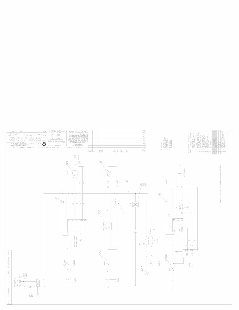
Electrical Schematic #3-4037

OUTOKUMPU TECHNOLOGY, INC. Physical Separation Division Operating Manual MIH(13)111-5
Revision 03-2 Page 2
1.0 SAFETY WARNINGS
SAFETY WARNINGS MUST BE READ BEFORE INSTALLING AND OPERATING THIS MACHINE!
• Have a qualified electrical maintenance technician install, adjust, and service
this equipment. Follow the National Electrical Code and all other applicable electrical and safety codes, including the provisions of the Occupational Safety and Health Act (OSHA) when installing and operating equipment.
1) LIFTING
• Caution: Lift with care using hoist bar inside cabinet, which is attached to magnet blocks.
• Attention: Remove the hoist bar before operating the separator.
• Caution: Move and locate this machine with caution. This machine weighs
approximately 425 pounds (193 kilograms). Proper care should be taken in mounting this unit to avoid unstable and potentially dangerous situations.
2) ELECTRICAL
• Reduce the chance of an electrical fire, shock, or explosion by proper grounding, over current protection, and thermal protection.
• Connect an adequate external grounding strap between the separator and a
water pipe or similar earthing. This external grounding strap may be omitted in installations where reliable, tested earth or ground connection is made via a proper three-pin plug or permanent wiring in accordance with local electrical codes.
• Check to insure that all electrical connections and voltage requirements are
in agreement with the electrical schematic shown in Appendix F prior to energizing the separator.
• Warning: Voltages encountered within this separator/controller are
dangerous and can be fatal. This separator/controller is designed to prevent accidental shock when properly used. However, no engineering design can render safe a device, which is used carelessly. Therefore, the instructions contained in the operating manual must be followed whenever this separator/controller is used.
OUTOKUMPU TECHNOLOGY, INC. Physical Separation Division Operating Manual MIH(13)111-5
Revision 03-2 Page 3
3) GENERAL
• Caution: When working with any dusty materials, care should be taken to provide operator(s) of laboratory or industrial separating devices with protective masks. Particular care should be taken when the materials are known to be hazardous or toxic, i.e., positive draft ventilation should be considered.
Warning/cautions tags are attached to the separator prior to shipment and precaution should be taken as specified to insure the safety of the personnel installing and operating this machinery.

OUTOKUMPU TECHNOLOGY, INC. Physical Separation Division Operating Manual MIH(13)111-5
Revision 03-2 Page 4
2.0 INSTALLATION 2.1 Drawings Refer to the general arrangement drawing and electrical schematic included in Appendix F of this operating manual before installing and operating this equipment. 2.2 General A carbon steel lifting handle is bolted to two eye bolts on the magnet blocks inside the separator cabinet. This handle should be used when moving the separator in conjunction with proper lifting equipment. Total static load: 425 pounds (193 kilograms). Note: This handle should be removed (unbolted) once the separator has been permanently installed to eliminate magnetic flux leakage which can occur through the carbon steel lift assembly. 2.3 Electrical Connections
Input Voltage: 115 VAC, 60 Hz, Single Phase
Caution: Check to insure that all electrical connections and voltage requirements are in agreement with the electrical schematic included in Appendix F prior to energizing separator. Grounding: Connect an adequate external grounding strap between the separator and a water pipe or similar earthing. This external grounding strap may be omitted in installations where reliable, tested earth or ground connection is made via a proper three-pin plug or permanent wiring in accordance with local electrical codes.

OUTOKUMPU TECHNOLOGY, INC. Physical Separation Division Operating Manual MIH(13)111-5
Revision 03-2 Page 5
3.0 SPECIFICATIONS Carpco Model MIH(13)111-5 Laboratory High-Intensity Induced-Roll Magnetic Separator is a top-fed laboratory/pilot-plant dry high-intensity electromagnetic separator designed to separate paramagnetic (weakly magnetic) materials from non-magnetic materials. This compact model is used extensively for bench and pilot-scale testing of granular materials, production control in plants using industrial high-intensity magnetic separators and for applied mineral research. 3.1 Principle of Operation This separator places all materials in contact with the highest magnetic field at the zones of steepest magnetic gradient and utilizes magnetic force and gravity to capture weakly magnetic materials. A turning magnetic roll used to transport materials through the active area provides an opposing centrifugal force for separation of magnetic and nonmagnetic materials. An illustration of the principle of operation is shown in Figure 1.
Figure 1: Principle of Operation 3.2 Standard Equipment Features
• Components and controls are built into a compact console so that the operator can easily observe and control separation simultaneously.
• A 62 in3 (1016 cm3) polished stainless steel velocity feed hopper equipped
with vibratory assist is used to control the rate of material being separated.
• A three-way product hopper of polished stainless steel construction permits collection of magnetic, middling and nonmagnetic products.

OUTOKUMPU TECHNOLOGY, INC. Physical Separation Division Operating Manual MIH(13)111-5
Revision 03-2 Page 6
• A 1/4-horsepower D.C. motor drive permits continuously variable roll speeds from 0 to 300 rpm.
• The separating roll is 5 inches (127 mm) in diameter by 2 inches (50 mm)
wide employing laminated magnetic/nonmagnetic materials of construction.
• Continuously variable input coil current (0-3 amperes) using solid-state D.C. rectification to an air-cooled magnet coil permits the magnetic field intensity of the separator to be adjustable as indicated in Figure 2 for varying gap settings.
Figure 2: Magnetic Field vs Field Current in Magnet Gap
• Both chrome-plated nose and tail pole pieces are adjustable to accommodate a wide range of particle sizes and magnetic field requirements.
• Fuses are installed in the major power circuits of the separator for the
protection of the associated components. They are easily accessible on the front panel and may be replaced by hand if an over current condition should occur.

OUTOKUMPU TECHNOLOGY, INC. Physical Separation Division Operating Manual MIH(13)111-5
Revision 03-2 Page 7
3.3 Optional Equipment Features (only if applicable) A Carpco Model MIH(13)111-5CX incorporates other optional features not included in the standard design of induced-roll separator.
• This variation of the standard design incorporates a modified magnet coil, which provides for cooling via a heat exchanger (provided separately) to reduce magnetic field variation that occurs due to changes in electrical resistance as heat builds up in the magnet coil.
• A constant current controller is provided to maintain a constant magnetic field
during prolonged operation. Additional details about this controller are included in the Other Manufacturer’s Information section of this operating manual.
• A heat exchanger is provided separately to provide the liquid cooling required
to properly operate the modified magnet coil and constant current features. Additional details about this heat exchanger are included in the Other Manufacturer’s Information section of this operating manual.
OUTOKUMPU TECHNOLOGY, INC. Physical Separation Division Operating Manual MIH(13)111-5
Revision 03-2 Page 8
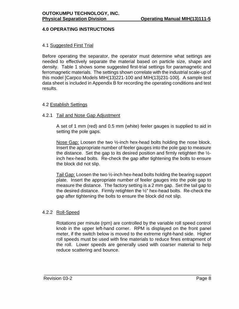
4.0 OPERATING INSTRUCTIONS 4.1 Suggested First Trial Before operating the separator, the operator must determine what settings are needed to effectively separate the material based on particle size, shape and density. Table 1 shows some suggested first-trial settings for paramagnetic and ferromagnetic materials. The settings shown correlate with the industrial scale-up of this model [Carpco Models MIH(13)221-100 and MIH(13)231-100]. A sample test data sheet is included in Appendix B for recording the operating conditions and test results. 4.2 Establish Settings 4.2.1 Tail and Nose Gap Adjustment
A set of 1 mm (red) and 0.5 mm (white) feeler gauges is supplied to aid in setting the pole gaps.
Nose Gap: Loosen the two ½-inch hex-head bolts holding the nose block. Insert the appropriate number of feeler gauges into the pole gap to measure the distance. Set the gap to its desired position and firmly retighten the ½-inch hex-head bolts. Re-check the gap after tightening the bolts to ensure the block did not slip.
Tail Gap: Loosen the two ½-inch hex-head bolts holding the bearing support plate. Insert the appropriate number of feeler gauges into the pole gap to measure the distance. The factory setting is a 2 mm gap. Set the tail gap to the desired distance. Firmly retighten the ½" hex-head bolts. Re-check the gap after tightening the bolts to ensure the block did not slip.
4.2.2 Roll-Speed
Rotations per minute (rpm) are controlled by the variable roll speed control knob in the upper left-hand corner. RPM is displayed on the front panel meter, if the switch below is moved to the extreme right-hand side. Higher roll speeds must be used with fine materials to reduce fines entrapment of the roll. Lower speeds are generally used with coarser material to help reduce scattering and bounce.

OUTOKUMPU TECHNOLOGY, INC. Physical Separation Division Operating Manual MIH(13)111-5
Revision 03-2 Page 9
Table 1: Suggested First-Trial Settings
Expected Response of
Tail Block
Nose Block
Roll Speed
Feed Rate
Magnet Current
Magnetic Particle
Particle Size
Gap (mm)
Gap (mm)
(rpm)
(lbs/hr/in)(kg/hr/cm)
(amps)
Paramagnetic
Coarse Particles
2
4-9
70-140
50-150
Up to 3.0
(Weakly Magnetic)
-6+28 mesh
(-3+0.6 mm)
12-27
Fine Particles
2
3-9
100-180
100-220
Up to 3.0 -28+200 mesh
(-0.6+0.074 mm)
24-40
Ferromagnetic
Coarse Particles
2
9
70-140
50-150
0.1-0.3
(Highly Magnetic)
-6+28 mesh
(-3+0.6 mm)
12-27
Fine Particles
2
9
100-180
100-220
0.1-0.3 -28+200 mesh
(-0.6+0.074 mm)
24-40
Notes: (1) Refer to Carpco's Electrostatic and Magnetic Separation Characteristics of Selected Mineral Chart for a guide as to paramagnetic or ferromagnetic characteristics of minerals
(Appendix A).
(2) Feed rate of laboratory separator is based on 1-1/2 inches (38.1 mm) effective feed width

OUTOKUMPU TECHNOLOGY, INC. Physical Separation Division Operating Manual MIH(13)111-5
Revision 03-2 Page 10
Figure 3 Velocity Feeder

OUTOKUMPU TECHNOLOGY, INC. Physical Separation Division Operating Manual MIH(13)111-5
Revision 03-2 Page 11
4.2.3 Feeding the Separator 4.2.3.1 Setting Feeder Position/Drop Height: Before setting the feed rate, the
total drop height of the velocity feed chute should be adjusted. For fine material, the longest drop height is required. A shorter drop height is appropriate for coarser materials. The following guidelines describe checking and adjusting the drop height and feeder position.
The first dimension to establish is the total drop height W (Figure 3). Once this has been decided, loosen the two thumbscrews on the sides of the hopper and move the hopper to the dimension desired. If necessary, swing the feed chute out of the way. The drop height may be measured easier with the help of a pair of calipers or dividers.
Next, the dimensions X and Y are both adjusted by means of the slotted clamp and thumbscrew shown in Figure 3. The dimension X (Figure 3) should be 1/4" - 3/8" (6-10mm) or at least large enough to pass the feed at the maximum rate desired without material piling up. The dimension Y (Figure 3) should be about 1/16" - 1/8" (1.5 - 3.0mm). It is very important when setting the feed chute that the back of the chute is set at an angle of 6 degrees from the vertical. This angle is built into the chute so that the falling stream of feed material is properly diverted and presented to the roll at the correct angle. Setting the chute at any other angle will upset the operation of the chute and defeat the advantages gained by its rise. Loosen the thumbscrew while holding the feed chute. The position of the chute may be moved in any direction horizontally or vertically by moving the thumbscrew along the slot provided and/or turning the slotted clamp (Figure 3) with the hand to enable movement in the direction desired. Always maintain the 6-degree angle of tilt on the back of the chute. The chute is clamped in its new position by tightening up the thumbscrew. Re-check dimensions X and Y and the 6 degree tilt after clamping. Turn on the roll momentarily to check adequate clearance Y. The final adjustment allows movement of the whole hopper and feeder assembly horizontally so that the feeder lip is positioned at the correct point on top of the roll. Usually a setting with the lip directly on top of the roll is used (at TDC; Top Dead Center). Any other setting is measured as an angle from TDC which is called BTDC (Before Top Dead Center); thus, positive angles BTDC shows a lip position in advance of the top of the roll (feeder lip to the left of top), and negative angles show a lip position after top dead center. The actual position may be selected while feed is flowing from the feeder by observing the degree of scattering and bounce produced by each position, then

OUTOKUMPU TECHNOLOGY, INC. Physical Separation Division Operating Manual MIH(13)111-5
Revision 03-2 Page 12
doing a trial separation. Angles too negative (after top dead center) may throw the feed over the roll without ever contacting it properly. Angles too far positive (before top dead center) may cause excessive impact with the roll.
Tighten the four thumbscrews involved in this adjustment after each setting.
4.2.3.2 Setting Feed Rate: Once the feeder position and drop height have
been set, the feed rate should be set as follows:
Equipment Needed: Stopwatch, sample of feed, collection pans and gram scale.
Note that the feed rate is controlled by both the feed gate adjustment and the variable vibrator control setting on the front panel. The feed gate adjustment is used for initial adjustment and the variable vibrator control is used to fine-tune the settings.
The feed gate must be opened further than the largest dimension of the material in the feeder to allow free flow. If part of the flow is blocked during feed tests, then increase the gate opening. Be aware of the possibility of other contaminants such as brush hairs, trash or oversize pieces of material present in the feed. Screening prior to separating may be used to deal with these problems.
To set the feed rate, follow the steps below:
1) Move the feed gate adjustment knob so that there is the correct gap
between the feed gate and the vibratory feed tray as follows:
Free Running Sand: 1/8"(3mm) Coarse Material: 1/4"(6mm) Ultra-fine Powders: 3/8"(9.5mm)
This is a starting point. Further adjustment may be made later while running to insure smooth feeding. Place pans under the product hoppers. Place the sample into the hopper, starting very gently so that sand does not spill from the feeder. Adjust the front panel feed rate control to about 50% (or other setting depending on previous tests or experience)
2) With stopwatch in hand, switch on the feeder for 10 seconds and collect the sample.

OUTOKUMPU TECHNOLOGY, INC. Physical Separation Division Operating Manual MIH(13)111-5
Revision 03-2 Page 13
3) Weigh the sample in grams and multiply this figure by 0.529 (0.0945) to obtain pounds/hour/inch (kg/hr/cm); or refer to Appendix C, Feed Rate Conversion Chart.
4) Repeat procedures 2 and 3, adjusting the feed rate controls for each
test until the desired rate is achieved. It is important to set the feed rate as high as possible to realize the full capacity of the industrial machine, while also being consistent with requirements of separation quality.
5) Once all adjustments have been set, feeding may be stopped and
started at will by the front panel toggle switch. This will enable timed runs to be accurately made, also when changing pans, without upsetting any of the rate adjustments mentioned above.
6) To simulate full-scale production units, feed rates should be 100-200
lb/hr/in (22.3-35.7 kg/hr/cm). Do not exceed 225 lb/hr/in (40 kg/hr/cm).
4.2.4 Splitters
After establishing all the previous settings, reload the material into the feed hopper. While the material is flowing, and with the magnet coil current off, set the right-hand splitter so that all material will just pass over this splitter into the nonmagnetic product bin. This setting is made using the locking adjustment knob on the front of the hopper.
4.2.5 Magnet Coil Current
Turn the magnet coil current on slowly and increase to the desired setting.
Note: The magnetic circuit is saturated at 3.0 amps and the current need not be set higher than this. The roll speed may vary when setting the magnet coil current; be sure to re-check this setting.
After establishing all the above settings, the separator should be allowed to warm up a few minutes prior to test work.
4.2.6 Roll Brush
It is good practice to empty the entrained particles from the roll brush after every test run. Lift the brush lever and slide the brush out of its holder. Tap the brush on the side of the pan holding the magnetics fraction. Use a 1" (2.5 cm) natural fiber (Chinese bristle) paintbrush to clean all three compartments of the product hoppers and brush holder assembly between tests.

OUTOKUMPU TECHNOLOGY, INC. Physical Separation Division Operating Manual MIH(13)111-5
Revision 03-2 Page 14
4.2.7 Adjustable Splitters
The splitters are fitted with adjustable height blades. To adjust for initial setup, loosen the thumbscrew on the nearest edge of the splitter and adjust to new height; retighten the thumbscrew. Measure the height of the top edge of the blade above the top of the splitter pivot bushing. To be equivalent to the industrial machine, this height should be 3-1/2" (89 mm) for both splitters. Operators may find, however, that better results may be obtained if the left-hand splitter (between middlings and magnetics) is lowered to 2-3/4" (70 mm). This will enable better performance where a middlings stream is desired while separating either coarse or extra fine material. This length splitter will also enable it to meet the roll at a lower position than would otherwise be obtained. Be aware that where only one splitter is used (e.g. after scalping or after first high-intensity separation) that the middlings and magnetics products are combined as a magnetics fraction and the only splitter used is the right-hand one. For convenience, the left-hand splitter may be parked up against the right-hand splitter thus shutting off the middlings fraction.

OUTOKUMPU TECHNOLOGY, INC. Physical Separation Division Operating Manual MIH(13)111-5
Revision 03-2 Page 15
5.0 MAINTENANCE 5.1 Belts Caution: Before any maintenance on the belts is performed, be sure to disconnect all power from the machine. Belts are accessed from the back of the separator. The motor-to-jackshaft belt can be adjusted by loosening the two bolts on the vertical of the jackshaft assembly. The jackshaft-to-roll belt is adjusted by loosening the two bolts on the horizontal of the jackshaft assembly. Be sure to firmly retighten all bolts after adjusting the belts. 5.2 Brush The roll brush should be properly spring-loaded against the roll by the brush holder mechanism. Do not operate without a brush, as this will not only damage the roll but will also give poor separation. The brush should be cleaned after every test run. Worn brushes should be replaced with genuine Carpco bristle roll stock. 5.3 Ventilation (applicable on standard MIH(13)111-5 only) A fan is provided to remove heat from inside the separator. After extended continuous use, the separator will get rather hot and this may result in reduced magnet current and possibly a tripped circuit breaker. If this occurs, turn the machine off and open the top door of the cabinet. Allow the machine to cool this way for ½ to 1 hour. Operation may then be resumed. 5.4 Spare Parts The recommended spare parts listing for this separator is included in Appendix D. 5.5 Motor Maintenance Lubrication and maintenance of the motor should follow guidelines given in Appendix E, Component Manufacturer’s Data. 5.6 Other Components Appendix E contains the manufacturer’s data for various components that are included in this separator.
OUTOKUMPU TECHNOLOGY, INC. Physical Separation Division Operating Manual MIH(13)111-5
Revision 03-2 Page 16
APPENDIX A
Separation Characteristics of Selected Minerals
OUTOKUMPU TECHNOLOGY, INC. Physical Separation Division Operating Manual MIH(13)111-5
Revision 03-2 Page 17
APPENDIX B
Laboratory Worksheet

OUTOKUMPU TECHNOLOGY, INC. Physical Separation Division Operating Manual MIH(13)111-5
Revision 03-2 Page 18
APPENDIX B
INDUCED-ROLL MAGNETIC SEPARATOR DATA SHEET
TECHNICIAN:______________________________ DATES TESTED:______________________ PROJECT NAME:_________________________ PROJECT NO.____________
TEST # STREAM NAME WT (G) % WT. CIR % WT. HF SAMPLE NO. MAGNETICS NONMAGNETICS FEED MAGNETICS NONMAGNETICS FEED MAGNETICS NONMAGNETICS FEED MAGNETICS NONMAGNETICS FEED OBSERVATIONS/COMMENTS:
OPERATING CONDITIONS TEST TEST TEST TEST FEED RATE (LBS/HR/IN) ROLL SPEED (RPM) FEED SPEED, oF (oC) INNER SPLITTER (INS) OUTER SPLITTER (INS) NOSE GAP (MM) TAIL GAP (MM)

OUTOKUMPU TECHNOLOGY, INC. Physical Separation Division Operating Manual MIH(13)111-5
Revision 03-2 Page 19
APPENDIX C
Feed Rate Conversion Chart

OUTOKUMPU TECHNOLOGY, INC. Physical Separation Division Operating Manual MIH(13)111-5
Revision 03-2 Page 20
APPENDIX C
FEED RATE CONVERSION CHARTMODEL MIH(13)111-5
SAMPLE WEIGHT FEED RATE SAMPLE WEIGHT FEED RATE(g/10 sec) (lbs/hr/in) (kg/hr/cm) (g/10 sec) (lbs/hr/in) (kg/hr/cm)
50.4 20 4.8 236 125 22.363.0 25 6.0 246 130 23.275.6 30 7.1 255 135 24.188.2 35 8.3 265 140 25.0100.8 40 9.5 274 145 25.9113.4 45 10.7 284 150 26.8125.9 50 11.9 293 155 27.6138.5 55 13.1 302 160 28.6151.1 60 14.3 312 165 29.4163.7 65 15.5 321 170 30.3176.3 70 16.7 331 175 31.2188.9 75 17.9 340 180 32.1201.5 80 19.0 350 185 33.0214.1 85 20.2 359 190 33.9226.7 90 21.4 369 195 34.8239.3 95 22.6 378 200 35.7251.9 100 23.8 388 205 36.6264.5 105 25.0 397 210 37.5277.1 110 26.2 406 215 38.4289.7 115 27.4 416 220 39.3302.3 120 28.6 425 225 40.1
CONVERSION FACTORS1) To convert g/10 sec to lbs/hr/in, multiply by 0.529.2) To convert g/10 sec to kg/hr/cm = multiply by 0.0945.

OUTOKUMPU TECHNOLOGY, INC. Physical Separation Division Operating Manual MIH(13)111-5
Revision 03-2 Page 21
APPENDIX D
Spare Parts Listing
OUTOKUMPU TECHNOLOGY, INC. Physical Separation Division Operating Manual MIH(13)111-5
Revision 03-2 Page 22
APPENDIX D
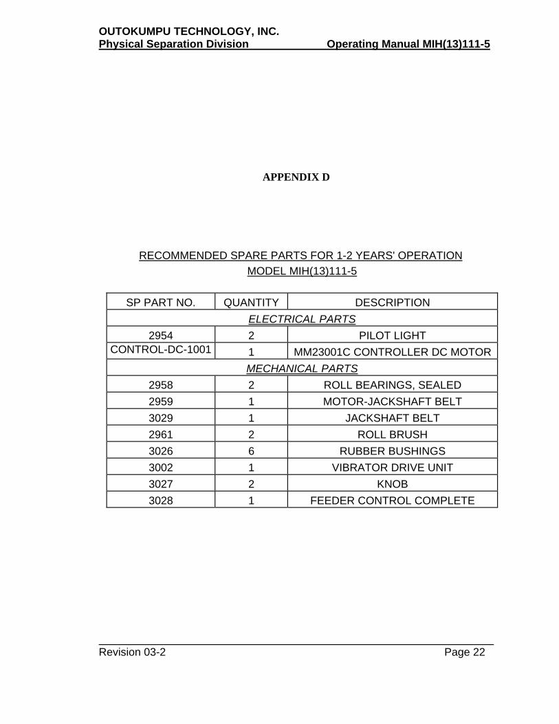
RECOMMENDED SPARE PARTS FOR 1-2 YEARS' OPERATION MODEL MIH(13)111-5
SP PART NO.
QUANTITY
DESCRIPTION
ELECTRICAL PARTS 2954
2
PILOT LIGHT
CONTROL-DC-1001
1 MM23001C CONTROLLER DC MOTOR
MECHANICAL PARTS 2958
2
ROLL BEARINGS, SEALED
2959
1
MOTOR-JACKSHAFT BELT 3029
1
JACKSHAFT BELT
2961
2
ROLL BRUSH 3026
6
RUBBER BUSHINGS
3002
1
VIBRATOR DRIVE UNIT 3027
2
KNOB
3028
1
FEEDER CONTROL COMPLETE

OUTOKUMPU TECHNOLOGY, INC. Physical Separation Division Operating Manual MIH(13)111-5
Revision 03-2 Page 23
APPENDIX E
COMPONENT MANUFACTURER’S DATA
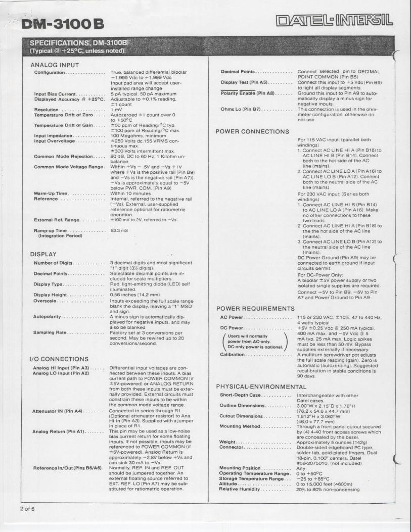
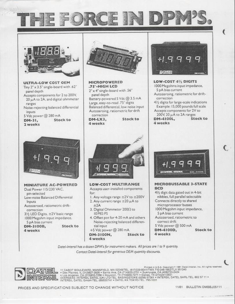
• Vibrator (FMC) • Digital Panel Meter (Datel)
• D.C. Motor and Speed Control (Minarik) • D.C. Tach Generator (Madison)
• Optional Constant Current Controller (applicable on Model MIH(13)111-5CX only)
• Optional Heat Exchanger (applicable on Model MIH(13)111-5CX only)


OUTOKUMPU TECHNOLOGY, INC. Physical Separation Division Operating Manual MIH(13)111-5
Revision 03-2 Page 24
APPENDIX F
DRAWINGS
General Arrangement Electrical Schematic

Recommended