Embed Size (px)
Citation preview

MANUAL NO. SIEP C730600 44A
Technical ManualCC-LinkType SI-C3
YASKAWA AC Drive-Option Card
To properly use the product, read this manual thoroughly and retain for easy reference, inspection, and maintenance. Ensure the end user receives this manual.

This Page Intentionally Blank
YASKAWA ELECTRIC SIEP C730600 44A YASKAWA AC Drive-Option Card CC-Link Technical Manual 3
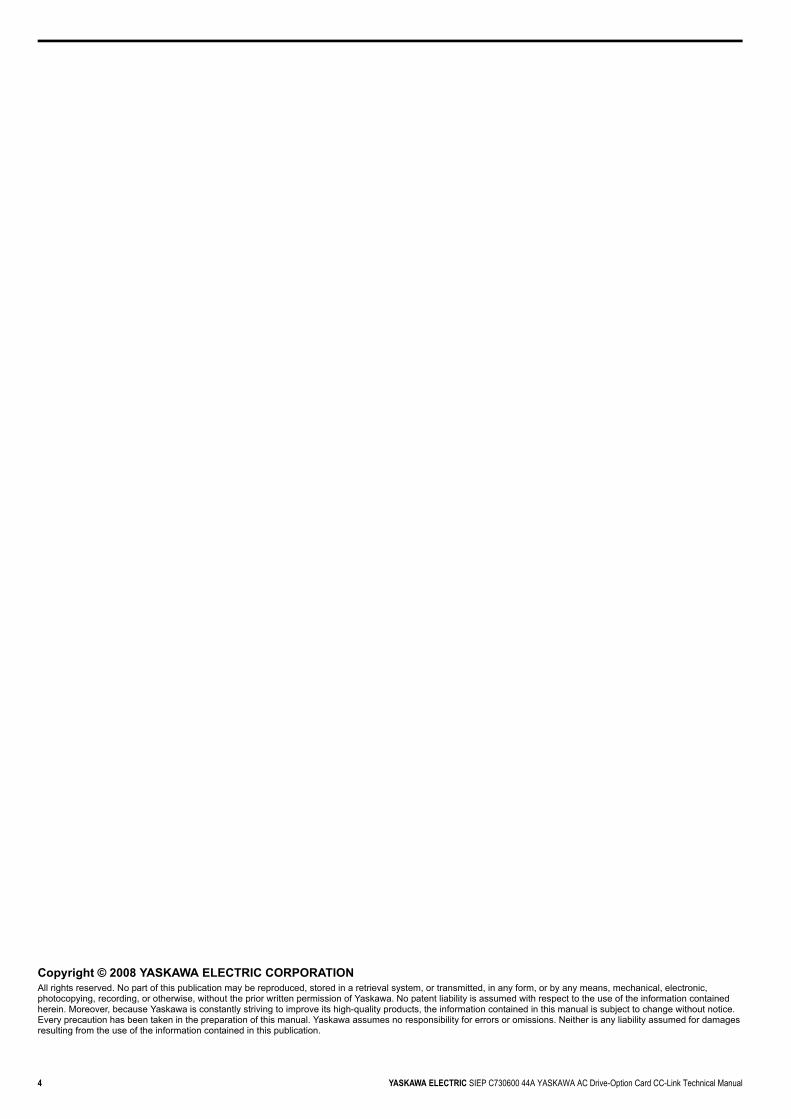
Table of Contents
1 PREFACE AND SAFETY . . . . . . . . . . . . . . . . . . . . . . . . . . . . . . . . . . . . . . . . . . . . . . . . . . . . . . . . . . . . . . . . 52 PRODUCT OVERVIEW. . . . . . . . . . . . . . . . . . . . . . . . . . . . . . . . . . . . . . . . . . . . . . . . . . . . . . . . . . . . . . . . . . 73 RECEIVING. . . . . . . . . . . . . . . . . . . . . . . . . . . . . . . . . . . . . . . . . . . . . . . . . . . . . . . . . . . . . . . . . . . . . . . . . . . 84 CC-LINK OPTION COMPONENTS . . . . . . . . . . . . . . . . . . . . . . . . . . . . . . . . . . . . . . . . . . . . . . . . . . . . . . . . 95 INSTALLATION PROCEDURE . . . . . . . . . . . . . . . . . . . . . . . . . . . . . . . . . . . . . . . . . . . . . . . . . . . . . . . . . . 116 CC-LINK OPTION DRIVE PARAMETERS. . . . . . . . . . . . . . . . . . . . . . . . . . . . . . . . . . . . . . . . . . . . . . . . . . 167 BASIC FUNCTIONS . . . . . . . . . . . . . . . . . . . . . . . . . . . . . . . . . . . . . . . . . . . . . . . . . . . . . . . . . . . . . . . . . . . 178 CC-LINK DATA TABLE . . . . . . . . . . . . . . . . . . . . . . . . . . . . . . . . . . . . . . . . . . . . . . . . . . . . . . . . . . . . . . . . 199 TROUBLESHOOTING . . . . . . . . . . . . . . . . . . . . . . . . . . . . . . . . . . . . . . . . . . . . . . . . . . . . . . . . . . . . . . . . . 2210 CC-LINK CODE NUMBERS . . . . . . . . . . . . . . . . . . . . . . . . . . . . . . . . . . . . . . . . . . . . . . . . . . . . . . . . . . . . 2611 SPECIFICATIONS. . . . . . . . . . . . . . . . . . . . . . . . . . . . . . . . . . . . . . . . . . . . . . . . . . . . . . . . . . . . . . . . . . . . 34
4 YASKAWA ELECTRIC SIEP C730600 44A YASKAWA AC Drive-Option Card CC-Link Technical Manual
Copyright © 2008 YASKAWA ELECTRIC CORPORATIONAll rights reserved. No part of this publication may be reproduced, stored in a retrieval system, or transmitted, in any form, or by any means, mechanical, electronic, photocopying, recording, or otherwise, without the prior written permission of Yaskawa. No patent liability is assumed with respect to the use of the information contained herein. Moreover, because Yaskawa is constantly striving to improve its high-quality products, the information contained in this manual is subject to change without notice. Every precaution has been taken in the preparation of this manual. Yaskawa assumes no responsibility for errors or omissions. Neither is any liability assumed for damages resulting from the use of the information contained in this publication.
1 Preface and Safety
YASKAWA ELECTRIC SIEP C730600 44A YASKAWA AC Drive-Option Card CC-Link Technical Manual 5
1 Preface and SafetyYaskawa manufactures products used as components in a wide variety of industrial systems and equipment. The selection and application of Yaskawa products remain the responsibility of the equipment manufacturer or end user. Yaskawa accepts no responsibility for the way its products are incorporated into the final system design. Under no circumstances should any Yaskawa product be incorporated into any product or design as the exclusive or sole safety control. Without exception, all controls should be designed to detect faults dynamically and fail safely under all circumstances. All systems or equipment designed to incorporate a product manufactured by Yaskawa must be supplied to the end user with appropriate warnings and instructions as to the safe use and operation of that part. Any warnings provided by Yaskawa must be promptly provided to the end user. Yaskawa offers an express warranty only as to the quality of its products in conforming to standards and specifications published in the Yaskawa manual. NO OTHER WARRANTY, EXPRESS OR IMPLIED, IS OFFERED. Yaskawa assumes no liability for any personal injury, property damage, losses, or claims arising from misapplication of its products.
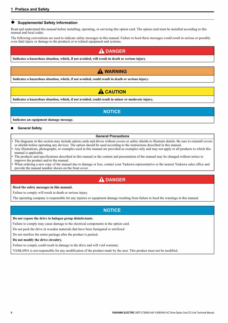
◆ Applicable DocumentationThe following manuals are available for the CC-Link Option:
◆ TermsNote: Indicates supplementary information that Yaskawa highly recommends be followed, even though equipment may not be at risk.
◆ Registered Trademarks• CC-Link is a registered trademark of the CC-Link Partner Association.• Other company names and product names listed in this manual are registered trademarks of those companies.
Option cardYASKAWA AC Drive-Option Card CC-Link Installation Manual Manual No. : TOBPC73060044Read this manual first.The installation manual is packaged with the CC-Link Option and contains a basic overview of wiring, settings, functions, and fault diagnoses.YASKAWA AC Drive-Option Card CC-Link Technical Manual Manual No. : SIEPC73060044The technical manual contains detailed information and command registers.To obtain the technical manual access the site below:http://www.e-mechatronics.com
Drive
Refer to the manual of the drive this option is being used with.The instruction manual for the drive covers basic installation, wiring, operation procedures, functions, troubleshooting, and maintenance information. It also includes important information on parameter settings and how to tune the drive.A Quick Start Guide is included with the drive. To obtain the Technical Manual, access Yaskawa’s homepage, http://www.e-mechatronics.com.
CC-Link Option: Yaskawa AC Drive SI-C3 CC-Link Option Card
1 Preface and Safety
6 YASKAWA ELECTRIC SIEP C730600 44A YASKAWA AC Drive-Option Card CC-Link Technical Manual
◆ Supplemental Safety InformationRead and understand this manual before installing, operating, or servicing this option card. The option card must be installed according to this manual and local codes.The following conventions are used to indicate safety messages in this manual. Failure to heed these messages could result in serious or possibly even fatal injury or damage to the products or to related equipment and systems.
■ General Safety
DANGER Indicates a hazardous situation, which, if not avoided, will result in death or serious injury.
W ARNING Indicates a hazardous situation, which, if not avoided, could result in death or serious injury.
CAUTION Indicates a hazardous situation, which, if not avoided, could result in minor or moderate injury.
NOTICEIndicates an equipment damage message.
General Precautions• The diagrams in this section may include option cards and drives without covers or safety shields to illustrate details. Be sure to reinstall covers
or shields before operating any devices. The option should be used according to the instructions described in this manual.• Any illustrations, photographs, or examples used in this manual are provided as examples only and may not apply to all products to which this
manual is applicable.• The products and specifications described in this manual or the content and presentation of the manual may be changed without notice to
improve the product and/or the manual.• When ordering a new copy of the manual due to damage or loss, contact your Yaskawa representative or the nearest Yaskawa sales office and
provide the manual number shown on the front cover.
DANGER Heed the safety messages in this manual.Failure to comply will result in death or serious injury.The operating company is responsible for any injuries or equipment damage resulting from failure to heed the warnings in this manual.
NOTICEDo not expose the drive to halogen group disinfectants.Failure to comply may cause damage to the electrical components in the option card. Do not pack the drive in wooden materials that have been fumigated or sterilized.Do not sterilize the entire package after the product is packed.Do not modify the drive circuitry.Failure to comply could result in damage to the drive and will void warranty. YASKAWA is not responsible for any modification of the product made by the user. This product must not be modified.
2 Product Overview
YASKAWA ELECTRIC SIEP C730600 44A YASKAWA AC Drive-Option Card CC-Link Technical Manual 7
2 Product Overview
◆ About This ProductCC-Link Option (Model: SI-C3) is designed for connecting a drive to a field network using the CC-Link protocol. This option is conforming to CC-Link Ver.1.10.By installing the CC-Link Option to a drive, it is possible to do the following from a CC-Link master device:• operate the drive• monitor the operation status of the drive• change parameter settings.
Figure 1
Figure 1 CC-Link Approved
8 YASKAWA ELECTRIC SIEP C730600 44A YASKAWA AC Drive-Option Card CC-Link Technical Manual
3 Receiving
3 ReceivingPlease perform the following tasks after receiving the CC-Link Option:• Inspect the CC-Link Option for damage.
If the CC-Link Option appears damaged upon receipt, contact the shipper immediately.• Verify receipt of the correct model by checking the information on the PCB (see Figure 2).• If you have received the wrong model or the CC-Link Option does not function properly, contact your supplier.
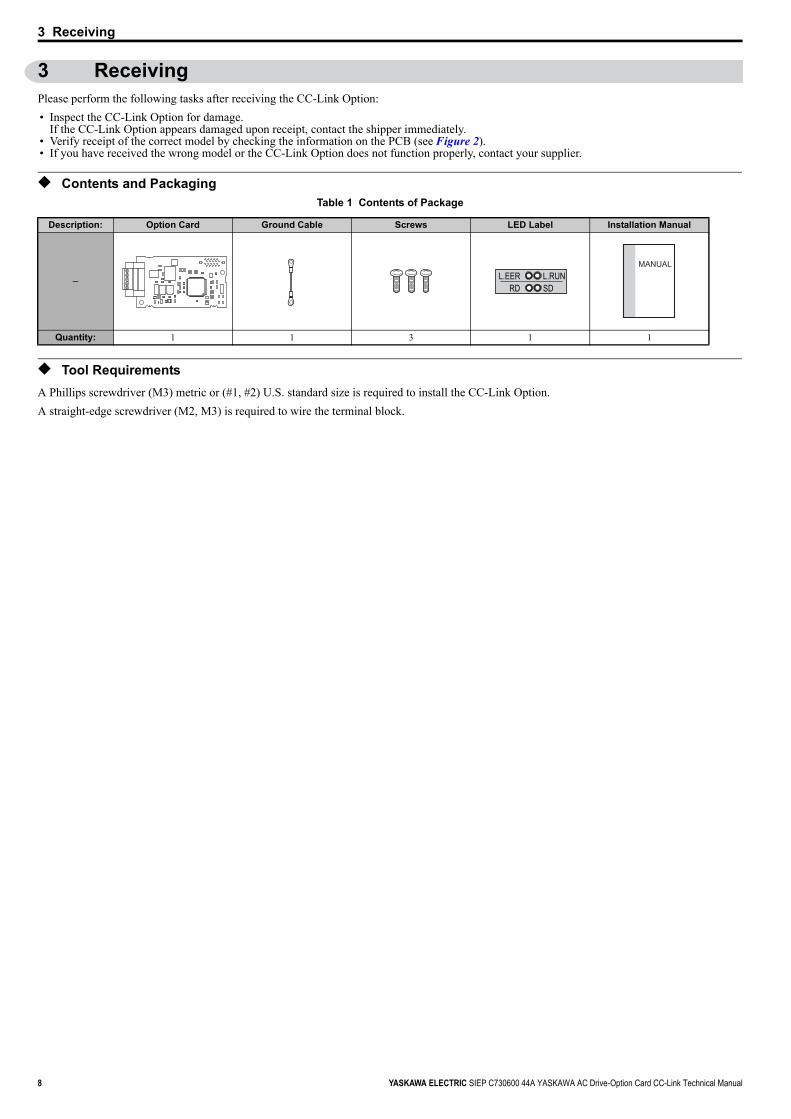
◆ Contents and PackagingTable 1 Contents of Package
◆ Tool RequirementsA Phillips screwdriver (M3) metric or (#1, #2) U.S. standard size is required to install the CC-Link Option.A straight-edge screwdriver (M2, M3) is required to wire the terminal block.
Description: Option Card Ground Cable Screws LED Label Installation Manual
−
Quantity: 1 1 3 1 1
L.EERRD
L.RUNSD
MANUAL

4 CC-Link Option Components
YASKAWA ELECTRIC SIEP C730600 44A YASKAWA AC Drive-Option Card CC-Link Technical Manual 9
4 CC-Link Option Components
◆ CC-Link OptionFigure 2
Figure 2 Option CardNote: For details on the LEDs, Refer to CC-Link Option LED Display on page 10 and Fault LED Display on CC-Link Option Side on page 23.
◆ Terminal BlockTable 2 Terminal Descriptions
Figure 3
Figure 3 CC-Link Option Terminal Block
A – Terminal block F – LED (L.RUN)B – Ground terminal (Installation Hole) G – Installation holeC – LED (L.ERR) H – Connector (CN5)D – LED (RD) I – PCB part numberE – LED (SD)
Terminal Name Description1 DA Comm. Data +2 DB Comm. Data –3 DG Signal Ground4 SLD Shield5 SLD Shield
Underside
A I
B C D
G
F
E
H
SI-C3
Top View
DA DB DG SLD SLD
Side View
4 CC-Link Option Components
10 YASKAWA ELECTRIC SIEP C730600 44A YASKAWA AC Drive-Option Card CC-Link Technical Manual
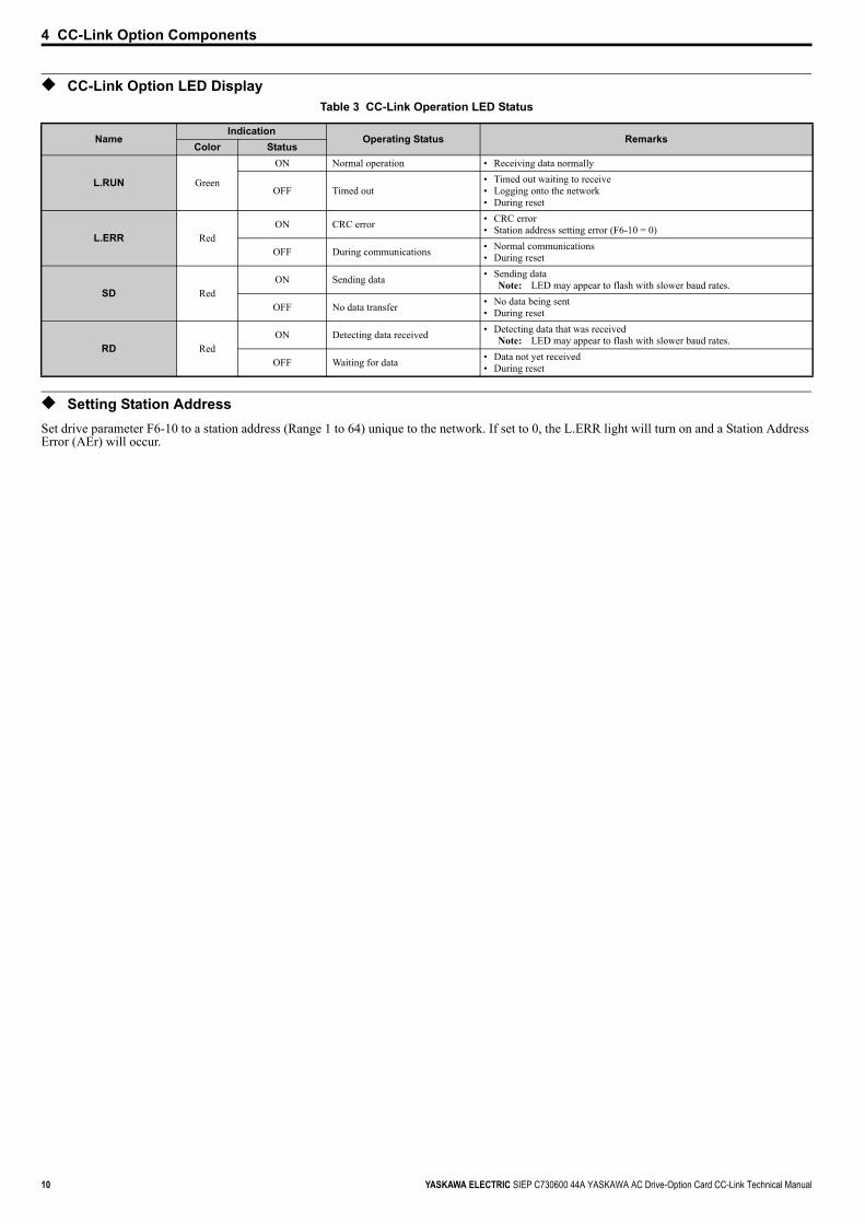
◆ CC-Link Option LED DisplayTable 3 CC-Link Operation LED Status
◆ Setting Station AddressSet drive parameter F6-10 to a station address (Range 1 to 64) unique to the network. If set to 0, the L.ERR light will turn on and a Station Address Error (AEr) will occur.
NameIndication
Operating Status RemarksColor Status
L.RUN Green
ON Normal operation • Receiving data normally
OFF Timed out• Timed out waiting to receive• Logging onto the network• During reset
L.ERR RedON CRC error • CRC error
• Station address setting error (F6-10 = 0)
OFF During communications • Normal communications• During reset
SD RedON Sending data • Sending data
Note: LED may appear to flash with slower baud rates.
OFF No data transfer • No data being sent• During reset
RD RedON Detecting data received • Detecting data that was received
Note: LED may appear to flash with slower baud rates.
OFF Waiting for data • Data not yet received• During reset
5 Installation Procedure
YASKAWA ELECTRIC SIEP C730600 44A YASKAWA AC Drive-Option Card CC-Link Technical Manual 11
5 Installation Procedure
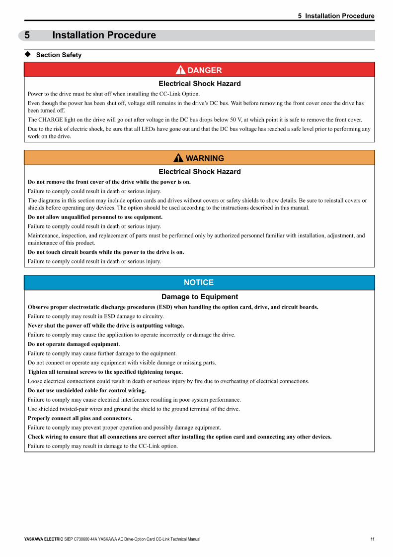
◆ Section Safety
DANGER Electrical Shock Hazard
Power to the drive must be shut off when installing the CC-Link Option.Even though the power has been shut off, voltage still remains in the drive’s DC bus. Wait before removing the front cover once the drive has been turned off.The CHARGE light on the drive will go out after voltage in the DC bus drops below 50 V, at which point it is safe to remove the front cover.Due to the risk of electric shock, be sure that all LEDs have gone out and that the DC bus voltage has reached a safe level prior to performing any work on the drive.
W ARNING Electrical Shock Hazard
Do not remove the front cover of the drive while the power is on.Failure to comply could result in death or serious injury.The diagrams in this section may include option cards and drives without covers or safety shields to show details. Be sure to reinstall covers or shields before operating any devices. The option should be used according to the instructions described in this manual.Do not allow unqualified personnel to use equipment. Failure to comply could result in death or serious injury.Maintenance, inspection, and replacement of parts must be performed only by authorized personnel familiar with installation, adjustment, and maintenance of this product.Do not touch circuit boards while the power to the drive is on.Failure to comply could result in death or serious injury.
NOTICE
Damage to EquipmentObserve proper electrostatic discharge procedures (ESD) when handling the option card, drive, and circuit boards.Failure to comply may result in ESD damage to circuitry.Never shut the power off while the drive is outputting voltage.Failure to comply may cause the application to operate incorrectly or damage the drive.Do not operate damaged equipment.Failure to comply may cause further damage to the equipment.Do not connect or operate any equipment with visible damage or missing parts.Tighten all terminal screws to the specified tightening torque.Loose electrical connections could result in death or serious injury by fire due to overheating of electrical connections.Do not use unshielded cable for control wiring.Failure to comply may cause electrical interference resulting in poor system performance. Use shielded twisted-pair wires and ground the shield to the ground terminal of the drive.Properly connect all pins and connectors. Failure to comply may prevent proper operation and possibly damage equipment. Check wiring to ensure that all connections are correct after installing the option card and connecting any other devices.Failure to comply may result in damage to the CC-Link option.

5 Installation Procedure
12 YASKAWA ELECTRIC SIEP C730600 44A YASKAWA AC Drive-Option Card CC-Link Technical Manual
◆ Connection DiagramTable 4 Connection Diagram
Using a single drive
<1> The user must set up the drive for terminal resistor. For instructions, see Terminal Resistor Connection on page 15.<2> Make sure that the FG terminal on the master drive is grounded properly.<3> The FE terminal on the CC-Link Option is supplied with a ground cable that should be connected to the ground terminal on the drive.
Using multiple drives
CC-LinkOption
DADBDGSLDSLD
DADBDGSLDFG
Masterdevice
CC-Link cable
DRIVE
Terminal resistor <1>
FE<2>
<3>
CC-LinkOption
DADBDGSLDSLD
CC-LinkOption
DADBDGSLDSLD
DADBDGSLDFG
CC-LinkOption
DADBDGSLDSLD
Masterdevice DRIVE
DRIVE
DRIVE
CC-Link cable
Terminal resistor <1>
FE
FE
FE
<2>
<3>
<3>
<3>

5 Installation Procedure
YASKAWA ELECTRIC SIEP C730600 44A YASKAWA AC Drive-Option Card CC-Link Technical Manual 13
◆ Prior to Installing the Option CardPrior to installing the DeviceNet Option, wire the drive and make necessary connections to the drive terminals. Refer to the Quick Start Guide for the drive the CC-Link Option is connected to for information on wiring and connecting the drive. Verify that the drive runs normally without the option installed.
◆ Installing the CC-Link OptionThis CC-Link Option can be inserted into the either only CN5-A connectors located on the drive’s control board.See the drive manual for directions on removing the front cover.
1. Shut off power to the drive, wait the appropriate amount of time for voltage to dissipate, then remove the operator and front cover.2. Insert the CN5 connector on the CC-Link Option into the matching CN5 connector on the drive, then fasten it into place using one of the
screws included with the CC-Link Option. Connect one of the lead lines using one of the screws to the ground terminal.Three separate lead lines have been included with the CC-Link Option to connect to three separate ports. Use the lead line with the length appropriate for the distance of the port.
Note: There are only two screw holes on the drive for ground terminals. If three option cards are connected, two of the lead lines will need to share the same ground terminal.Figure 4
Figure 4 Installing the Option
3. Wire the CC-Link Option to the terminal block on the CC-Link Option.For wiring instructions, see Connection Diagram on page 12.For exposed cables in drives 2A004 to 0069, 4A0002 to 0044, use a pair of wire cutters to create an opening on the left side of the front cover that allows wiring to pass through. Sharp edges along the opening that was created should be smoothed down with a file or sand paper so prevent any damage to the wires. Drives 2A0081 to 0021, 4A0058 to 0165 have enough space to keep all wiring inside the unit.
Figure 5
Figure 5 Wiring space
4. Place the front cover back onto the drive as it was before.
Note: 1. Take care when wiring the CC-Link Option so that the front cover easily fits back onto the drive.2. Install Cable Cover option to maintain the drive Enclosure Type.
A – Connector CN5-C G – Lead lineB – Connector CN5-B H – Use wire cutters to create an
opening for cable linesC – Connector CN5-A I – OperatorD – Drive grounding terminal (FE) J – LED labelE – Insert connector CN5 here K – Front coverF – CC-Link Option
A – Cable through hole(2A0004 to 0069, 4A0002 to 0044)
B – Space for wiring(2A0081 to 0021, 4A0058 to 0165)
REVDRV
LERRFOUT
G
A
EF
I
J
B
C
D
H
K
B
A
5 Installation Procedure
14 YASKAWA ELECTRIC SIEP C730600 44A YASKAWA AC Drive-Option Card CC-Link Technical Manual
◆ Communication Cable Wiring
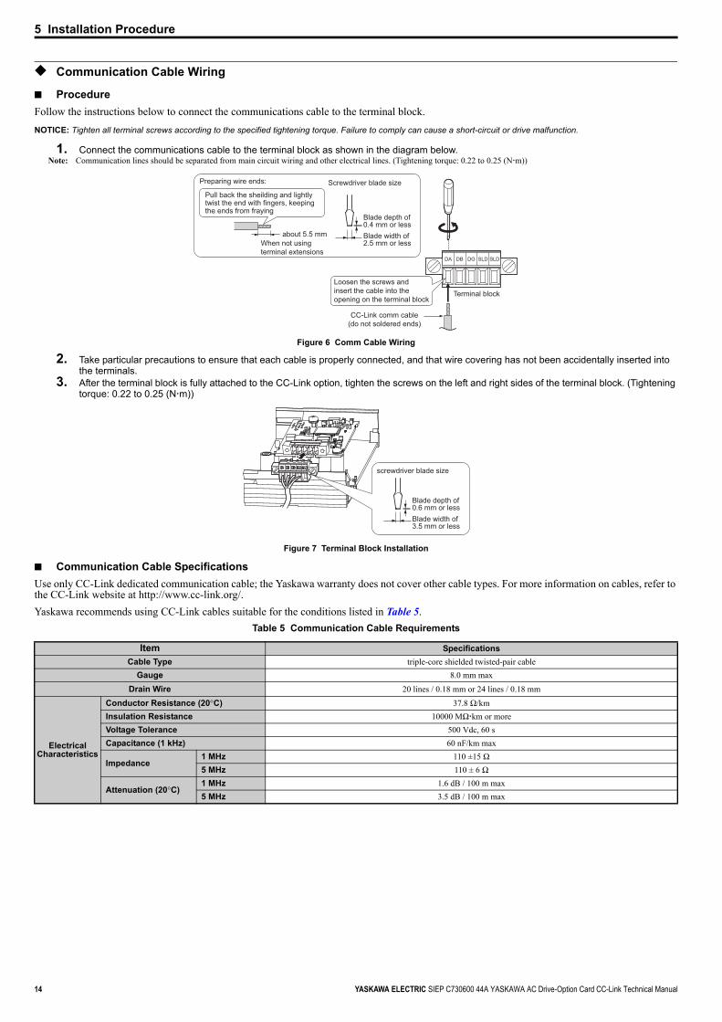
■ ProcedureFollow the instructions below to connect the communications cable to the terminal block.NOTICE: Tighten all terminal screws according to the specified tightening torque. Failure to comply can cause a short-circuit or drive malfunction.
1. Connect the communications cable to the terminal block as shown in the diagram below.Note: Communication lines should be separated from main circuit wiring and other electrical lines. (Tightening torque: 0.22 to 0.25 (N m))
Figure 6
Figure 6 Comm Cable Wiring
2. Take particular precautions to ensure that each cable is properly connected, and that wire covering has not been accidentally inserted into the terminals.
3. After the terminal block is fully attached to the CC-Link option, tighten the screws on the left and right sides of the terminal block. (Tightening torque: 0.22 to 0.25 (N m))
Figure 7
Figure 7 Terminal Block Installation
■ Communication Cable SpecificationsUse only CC-Link dedicated communication cable; the Yaskawa warranty does not cover other cable types. For more information on cables, refer to the CC-Link website at http://www.cc-link.org/.Yaskawa recommends using CC-Link cables suitable for the conditions listed in Table 5.
Table 5 Communication Cable Requirements
Item SpecificationsCable Type triple-core shielded twisted-pair cable
Gauge 8.0 mm max
Drain Wire 20 lines / 0.18 mm or 24 lines / 0.18 mm
Electrical Characteristics
Conductor Resistance (20°C) 37.8 Ω/kmInsulation Resistance 10000 MΩ km or moreVoltage Tolerance 500 Vdc, 60 sCapacitance (1 kHz) 60 nF/km max
Impedance1 MHz 110 ±15 Ω5 MHz 110 ± 6 Ω
Attenuation (20°C)1 MHz 1.6 dB / 100 m max5 MHz 3.5 dB / 100 m max
DA DB DG SLD SLD
Terminal block
Preparing wire ends: Screwdriver blade size
When not usingterminal extensions
about 5.5 mm
Pull back the sheilding and lightly twist the end with fingers, keeping the ends from fraying
CC-Link comm cable(do not soldered ends)
Loosen the screws and insert the cable into the opening on the terminal block
Blade depth of 0.4 mm or lessBlade width of 2.5 mm or less
screwdriver blade size
Blade depth of 0.6 mm or lessBlade width of 3.5 mm or less
5 Installation Procedure
YASKAWA ELECTRIC SIEP C730600 44A YASKAWA AC Drive-Option Card CC-Link Technical Manual 15
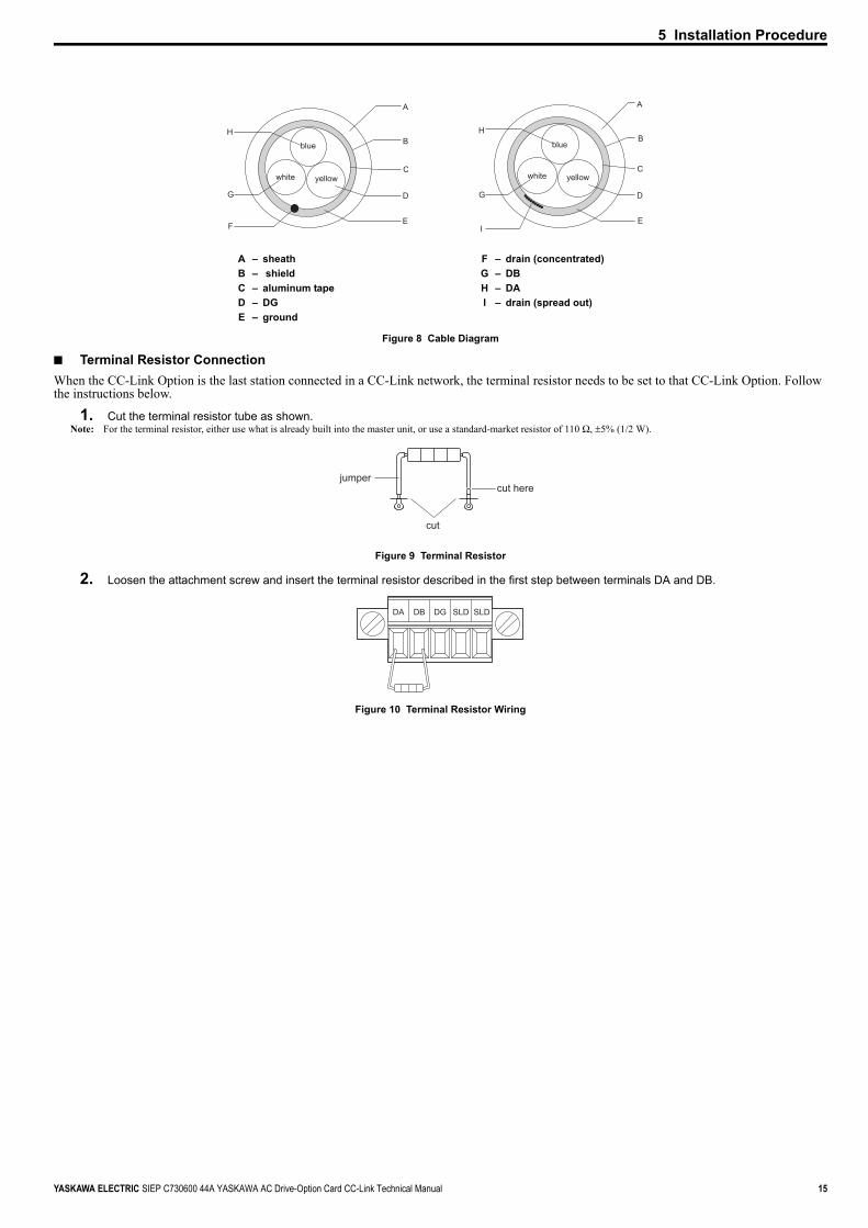
Figure 8
Figure 8 Cable Diagram
■ Terminal Resistor ConnectionWhen the CC-Link Option is the last station connected in a CC-Link network, the terminal resistor needs to be set to that CC-Link Option. Follow the instructions below.
1. Cut the terminal resistor tube as shown.Note: For the terminal resistor, either use what is already built into the master unit, or use a standard-market resistor of 110 Ω, ±5% (1/2 W).
Figure 9
Figure 9 Terminal Resistor
2. Loosen the attachment screw and insert the terminal resistor described in the first step between terminals DA and DB.Figure 10
Figure 10 Terminal Resistor Wiring
A – sheath F – drain (concentrated)B – shield G – DBC – aluminum tape H – DAD – DG I – drain (spread out)E – ground
A
B
C
D
E
H
G
F
white
blue
yellow
A
B
C
D
E
H
G
I
white
blue
yellow
jumpercut here
cut
DA DB DG SLD SLD
16 YASKAWA ELECTRIC SIEP C730600 44A YASKAWA AC Drive-Option Card CC-Link Technical Manual
6 CC-Link Option Drive Parameters
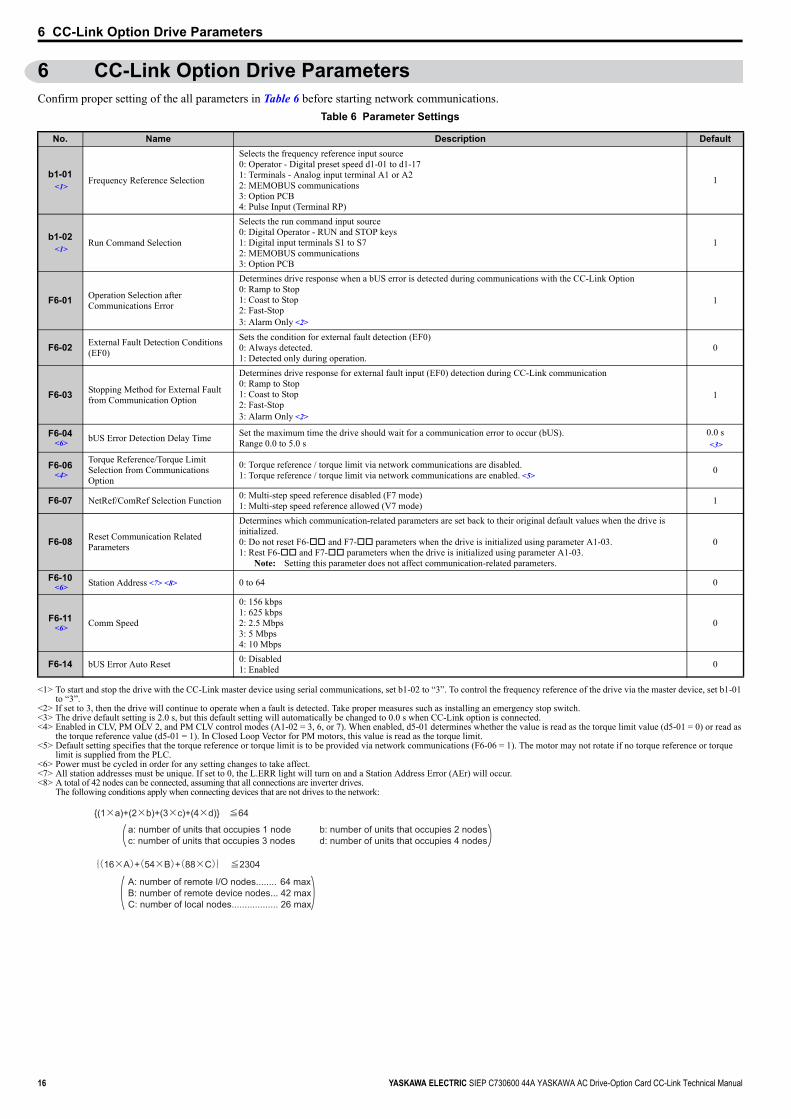
6 CC-Link Option Drive ParametersConfirm proper setting of the all parameters in Table 6 before starting network communications.
Table 6 Parameter Settings
No. Name Description Default
b1-01<1>
<1> To start and stop the drive with the CC-Link master device using serial communications, set b1-02 to “3”. To control the frequency reference of the drive via the master device, set b1-01
to “3”.<2> If set to 3, then the drive will continue to operate when a fault is detected. Take proper measures such as installing an emergency stop switch.<3> The drive default setting is 2.0 s, but this default setting will automatically be changed to 0.0 s when CC-Link option is connected.<4> Enabled in CLV, PM OLV 2, and PM CLV control modes (A1-02 = 3, 6, or 7). When enabled, d5-01 determines whether the value is read as the torque limit value (d5-01 = 0) or read as
the torque reference value (d5-01 = 1). In Closed Loop Vector for PM motors, this value is read as the torque limit.<5> Default setting specifies that the torque reference or torque limit is to be provided via network communications (F6-06 = 1). The motor may not rotate if no torque reference or torque
limit is supplied from the PLC.<6> Power must be cycled in order for any setting changes to take affect.<7> All station addresses must be unique. If set to 0, the L.ERR light will turn on and a Station Address Error (AEr) will occur.<8> A total of 42 nodes can be connected, assuming that all connections are inverter drives.
The following conditions apply when connecting devices that are not drives to the network:
Frequency Reference Selection
Selects the frequency reference input source0: Operator - Digital preset speed d1-01 to d1-171: Terminals - Analog input terminal A1 or A22: MEMOBUS communications 3: Option PCB4: Pulse Input (Terminal RP)
1
b1-02<1>
Run Command Selection
Selects the run command input source0: Digital Operator - RUN and STOP keys1: Digital input terminals S1 to S7 2: MEMOBUS communications 3: Option PCB
1
F6-01 Operation Selection after Communications Error
Determines drive response when a bUS error is detected during communications with the CC-Link Option0: Ramp to Stop 1: Coast to Stop2: Fast-Stop3: Alarm Only <2>
1
F6-02 External Fault Detection Conditions (EF0)
Sets the condition for external fault detection (EF0)0: Always detected.1: Detected only during operation.
0
F6-03 Stopping Method for External Fault from Communication Option
Determines drive response for external fault input (EF0) detection during CC-Link communication0: Ramp to Stop 1: Coast to Stop2: Fast-Stop3: Alarm Only <2>
1
F6-04<6> bUS Error Detection Delay Time Set the maximum time the drive should wait for a communication error to occur (bUS).
Range 0.0 to 5.0 s0.0 s<3>
F6-06<4>
Torque Reference/Torque Limit Selection from Communications Option
0: Torque reference / torque limit via network communications are disabled.1: Torque reference / torque limit via network communications are enabled. <5>
0
F6-07 NetRef/ComRef Selection Function 0: Multi-step speed reference disabled (F7 mode)1: Multi-step speed reference allowed (V7 mode) 1
F6-08 Reset Communication Related Parameters
Determines which communication-related parameters are set back to their original default values when the drive is initialized.0: Do not reset F6- and F7- parameters when the drive is initialized using parameter A1-03.1: Rest F6- and F7- parameters when the drive is initialized using parameter A1-03.
Note: Setting this parameter does not affect communication-related parameters.
0
F6-10<6> Station Address <7> <8> 0 to 64 0
F6-11<6> Comm Speed
0: 156 kbps1: 625 kbps2: 2.5 Mbps3: 5 Mbps4: 10 Mbps
0
F6-14 bUS Error Auto Reset 0: Disabled1: Enabled 0
A: number of remote I/O nodes........ 64 max
B: number of remote device nodes... 42 max
C: number of local nodes.................. 26 max
a: number of units that occupies 1 node b: number of units that occupies 2 nodes
c: number of units that occupies 3 nodes d: number of units that occupies 4 nodes
{(1×a)+(2×b)+(3×c)+(4×d)} ≦64
{(16×A)+(54×B)+(88×C)} ≦2304
(( )
)
7 Basic Functions
YASKAWA ELECTRIC SIEP C730600 44A YASKAWA AC Drive-Option Card CC-Link Technical Manual 17
7 Basic FunctionsThis interface allows the drive to be connected to a CC-Link network as a remote device, making it possible to operate, adjust settings, and monitor the operation status of the drive using the PLC program. Both bit and word data cyclic transmission are available, and high speed communication up to 10 Mbps is possible.Below is a description of the basic CC-Link functions that can be performed by the PLC.
Note: Set parameters when operating the drive from a PLC. For instructions, see CC-Link Option Drive Parameters on page 16.
◆ Switching Between Command/Reference SourcesThe Run command, Stop command, and the frequency reference can be entered directly from the operator or given from a separate control device.To use a separate control device to issue the Run command and frequency reference, the drive needs to be set so that it accepts theses commands from an external source.
■ Selecting an External SourceFollow the directions below set the drive up to accept commands from an external controller.• Using Parameters to Select the Command/Reference Source• Using the External Terminals to Switch the Command/Reference Source• Using a PLC as the Command/Reference Source
■ Using Parameters to Select the Command/Reference SourceSelecting the Run Command SourceSet b1-02 (Run Command Selection) to 3 ("Option PCB").Selecting the Source of the Frequency ReferenceSet b1-01 (Frequency Reference Selection) to 3 (“Option PCB”).
■ Using the External Terminals to Switch the Command/Reference SourceSelecting the Run Command Source 2Set b1-16 (Run Command Source 2) to 3 (“Option card”).Selecting the Source of the Frequency Reference 2Set b1-15 (Frequency Reference Source 2) to 3 (“Option card”).Selecting the Run Command and Frequency Reference SourceBy setting one of the multi-function input terminals S1 through S8 to supply auxiliary reference (H1-01 to H1-08 = 2), then the frequency reference set to b1-15 and the run command source set to b1-16 will become enabled.
■ Using a PLC as the Command/Reference SourceUsing Parameters to Switch Sources
Note: By setting H1- = 2, then parameters b1-15 and b1-16 will become enabled when that terminal is switched on.• Selecting the Run Command Source
Send write data “3” for command code 2181H to the drive.The setting for parameter b1-02 changes to “3”.
• Frequency Reference Source SelectionSend write data “3” for command code 2180H to the drive.The setting for parameter b1-01 changes to “3”.
Using NetRef and NetCtrlIt is also possible to change the source of the frequency reference and the Run command using remote register RWW2 command code 00FBH.If the power is shut off, however, the drive will use the original setting for the command/reference source once the power is turned back again. This method should therefore only be used when briefly switching between command/reference sources.

7 Basic Functions
18 YASKAWA ELECTRIC SIEP C730600 44A YASKAWA AC Drive-Option Card CC-Link Technical Manual
■ Command/Reference Source Priority Using a PLCRun Command Source
Table 7 Run Command Source Priority
Note: Dash indicates that the setting has no effect on the source of the Run command.
Frequency Reference SourceTable 8 Frequency Reference Source Priority
Note: 1. When the multi-function input terminals are set up for Multi-Step Speed operation, parameters d1-01 through d1-16 take priority as the source of the frequency reference (assuming that F6-07 = 1).
2. Dash indicates that the setting has no effect on the source of the frequency reference.3. Refer to the technical manual for the drive the CC-Link Option is connected to for more details on parameter settings.
◆ MonitorsThe user can monitor drive operating status from a PLC.To do so, the monitor should be set up as follows:
1. Sets the monitor code to the remote register RWW0.
2. Switch the RYC signal on.• Data for the monitor code is stored in the PLC’s buffer memory.
Note: Monitor codes and units are listed in Monitor Codes on page 28.
◆ Reading and Setting ParametersThe PLC can write drive parameters, read drive data and operation status, and change settings.Follow the directions below.
1. Set the command code to remote register RWW2.• Set the write data to RWW3 as needed.
2. Switch on the RYF signal (request to execute the command code).• Drive executes the process and reply data that correspond with the command code.• Command codes for drive parameters should be calculated by adding the values shown below to the MEMOBUS register number.
Read command code: MEMOBUS register + 1000HWrite command code: MEMOBUS register + 2000H
EXAMPLE: Acceleration time command code for C1-01 is 200H. Get the read command code by adding 1000H, yielding 1200HNote: 1. For a list of command codes, write data units, and setting ranges, refer to Command Codes on page 26 and Extended Command Codes on page 27.
2. Refer to the MEMOBUS/Modbus Data Table in Appendix C of the technical manual for the drive the CC-Link Option is connected to for a list of monitor data using the MEMOBUS/Modbus message area.
Setting StatusNetCtrl 1 0 0 0 0 0
LOCAL/REMOTE Selection – LOCAL REMOTESwitching Command Source – – OFF ONRun Command Selection 1
b1-02 – – 3 not 3 – –
Run Command Selection 2b1-16 – – – – 3 not 3
Run Command Source PLC Operator PLC Determined by b1-02 PLC Determined by b1-16
Setting StatusNetRef 1 0 0 0 0 0
LOCAL/REMOTE Selection – LOCAL REMOTESwitching Reference Source – – OFF ON
Frequency Reference Selection 1b1-01 – – 3 not 3 – –
Frequency Reference Selection 2b1-15 – – – – 3 not 3
Frequency Reference Source PLC Operator PLC Determined by b1-01 PLC Determined by b1-15
8 CC-Link Data Table
YASKAWA ELECTRIC SIEP C730600 44A YASKAWA AC Drive-Option Card CC-Link Technical Manual 19
8 CC-Link Data Table
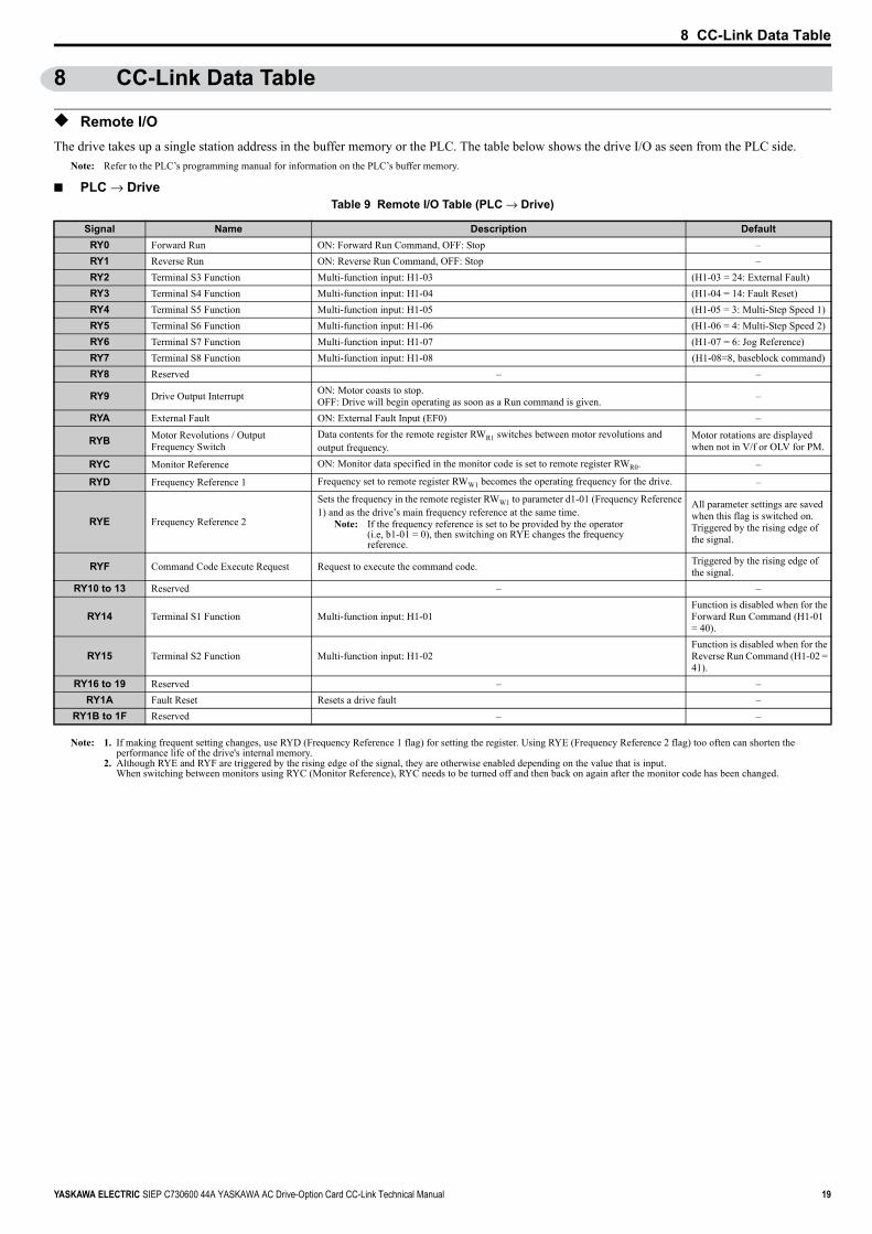
◆ Remote I/OThe drive takes up a single station address in the buffer memory or the PLC. The table below shows the drive I/O as seen from the PLC side.
Note: Refer to the PLC’s programming manual for information on the PLC’s buffer memory.
■ PLC → DriveTable 9 Remote I/O Table (PLC → Drive)
Note: 1. If making frequent setting changes, use RYD (Frequency Reference 1 flag) for setting the register. Using RYE (Frequency Reference 2 flag) too often can shorten the performance life of the drive's internal memory.
2. Although RYE and RYF are triggered by the rising edge of the signal, they are otherwise enabled depending on the value that is input. When switching between monitors using RYC (Monitor Reference), RYC needs to be turned off and then back on again after the monitor code has been changed.
Signal Name Description DefaultRY0 Forward Run ON: Forward Run Command, OFF: Stop –RY1 Reverse Run ON: Reverse Run Command, OFF: Stop –RY2 Terminal S3 Function Multi-function input: H1-03 (H1-03 = 24: External Fault)RY3 Terminal S4 Function Multi-function input: H1-04 (H1-04 = 14: Fault Reset)RY4 Terminal S5 Function Multi-function input: H1-05 (H1-05 = 3: Multi-Step Speed 1)RY5 Terminal S6 Function Multi-function input: H1-06 (H1-06 = 4: Multi-Step Speed 2)RY6 Terminal S7 Function Multi-function input: H1-07 (H1-07 = 6: Jog Reference)RY7 Terminal S8 Function Multi-function input: H1-08 (H1-08=8, baseblock command)RY8 Reserved – –
RY9 Drive Output Interrupt ON: Motor coasts to stop.OFF: Drive will begin operating as soon as a Run command is given. –
RYA External Fault ON: External Fault Input (EF0) –
RYB Motor Revolutions / Output Frequency Switch
Data contents for the remote register RWR1 switches between motor revolutions and output frequency.
Motor rotations are displayed when not in V/f or OLV for PM.
RYC Monitor Reference ON: Monitor data specified in the monitor code is set to remote register RWR0. –
RYD Frequency Reference 1 Frequency set to remote register RWW1 becomes the operating frequency for the drive. –
RYE Frequency Reference 2
Sets the frequency in the remote register RWW1 to parameter d1-01 (Frequency Reference 1) and as the drive’s main frequency reference at the same time.
Note: If the frequency reference is set to be provided by the operator(i.e, b1-01 = 0), then switching on RYE changes the frequency reference.
All parameter settings are saved when this flag is switched on.Triggered by the rising edge of the signal.
RYF Command Code Execute Request Request to execute the command code. Triggered by the rising edge of the signal.
RY10 to 13 Reserved – –
RY14 Terminal S1 Function Multi-function input: H1-01Function is disabled when for the Forward Run Command (H1-01 = 40).
RY15 Terminal S2 Function Multi-function input: H1-02Function is disabled when for the Reverse Run Command (H1-02 = 41).
RY16 to 19 Reserved – –RY1A Fault Reset Resets a drive fault –
RY1B to 1F Reserved – –
8 CC-Link Data Table
20 YASKAWA ELECTRIC SIEP C730600 44A YASKAWA AC Drive-Option Card CC-Link Technical Manual
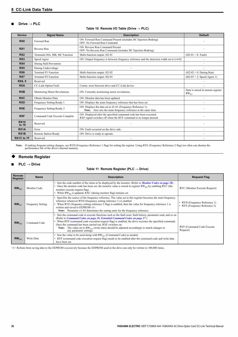
■ Drive → PLCTable 10 Remote I/O Table (Drive → PLC)
Note: If making frequent setting changes, use RYD (Frequency Reference 1 flag) for setting the register. Using RYE (Frequency Reference 2 flag) too often can shorten the performance life of the drive's internal memory.
◆ Remote Register
■ PLC → DriveTable 11 Remote Register (PLC → Drive)
Device Signal Name Description Default
RX0 Forward Run ON: Forward Run Command Present (includes DC Injection Braking)OFF: No Forward Run Command –
RX1 Reverse Run ON: Reverse Run Command PresentOFF: No Reverse Run Command (includes DC Injection Braking) –
RX2 Terminals MA, MB, MC Function Multi-function output: H2-01 (H2-01 = E: Fault)RX3 Speed Agree ON: Output frequency is between frequency reference and the detection width set to L4-02. –RX4 During Stall Prevention – –RX5 During Undervoltage – –RX6 Terminal P1 Function Multi-function output: H2-02 (H2-02 = 0: During Run)RX7 Terminal P2 Function Multi-function output: H2-03 (H2-03 = 2: Speed Agree 1)
RX8, 9 Reserved – –RXA CC-Link Option Fault Comm. error between drive and CC-Link device –
RXB Monitoring Motor Revolutions ON: Currently monitoring motor revolutions. Data is stored in remote register RWR1.
RXC Obtain Monitor Data ON: Monitor data has been updated. –RXD Frequency Setting Ready 1 ON: Displays the main frequency reference that has been set. –
RXE Frequency Setting Ready 2 ON: Displays the data set to d1-01 (Frequency Reference 1).Note: Also sets the main frequency reference at the same time. –
RXF Command Code Execute Complete ON: Displayed after the specified command code has been executed.RXF signal switches off when the RYF command is no longer present. –
RX10 to 19 Reserved – –
RX1A Error ON: Fault occurred on the drive side. –RX1B Remote Station Ready ON: Drive is ready to operate. –
RX1C to 1F Reserved – –
Remote Register Name Description Request Flag
RWW0
<1> Refrain from saving data to the EEPROM excessively because the EEPROM used in the drive can only be written to 100,000 times.
Monitor Code
• Sets the code number of the items to be displayed by the monitor. (Refer to Monitor Codes on page 28).• Once the monitor code has been set, the monitor value is stored in register RWR0 by enabling RYC (the
monitor execute request flag).• While RWR0 is updated, RXC (during monitor flag) remains on.
RYC (Monitor Execute Request)
RWW1 Frequency Setting
• Specifies the source of the frequency reference. The value set to this register becomes the main frequency reference whenever RYD (frequency setting reference 1) is enabled.
• When RYE (frequency setting reference 2 flag) is enabled, then the value for frequency reference 1 is written and saved to EEPROM <1>.
Note: Parameter o1-03 determines the setting units for the frequency reference.
• RYD (Frequency Reference 1)• RYE (Frequency Reference 2)
RWW2 Command Code
• Sets the command code to execute functions such as the fault reset, fault history, parameter read, and so on. (Refer to Command Codes on page 26, Extended Command Codes on page 27.)
• When RYF (command code execution request flag) is enabled, the drive executes the specified command. Once the command has been carried out, RXF switches on.
Note: The value set to RWW3 (write data) should be adjusted accordingly to match changes to any parameter settings.
RYF (Command Code Execute Request)
RWW3 Write Data• Sets the value to be used along with RWW2 (Command Code) as needed.• RYF (command code execution request flag) needs to be enabled after the command code and write data
have been set.
8 CC-Link Data Table
YASKAWA ELECTRIC SIEP C730600 44A YASKAWA AC Drive-Option Card CC-Link Technical Manual 21
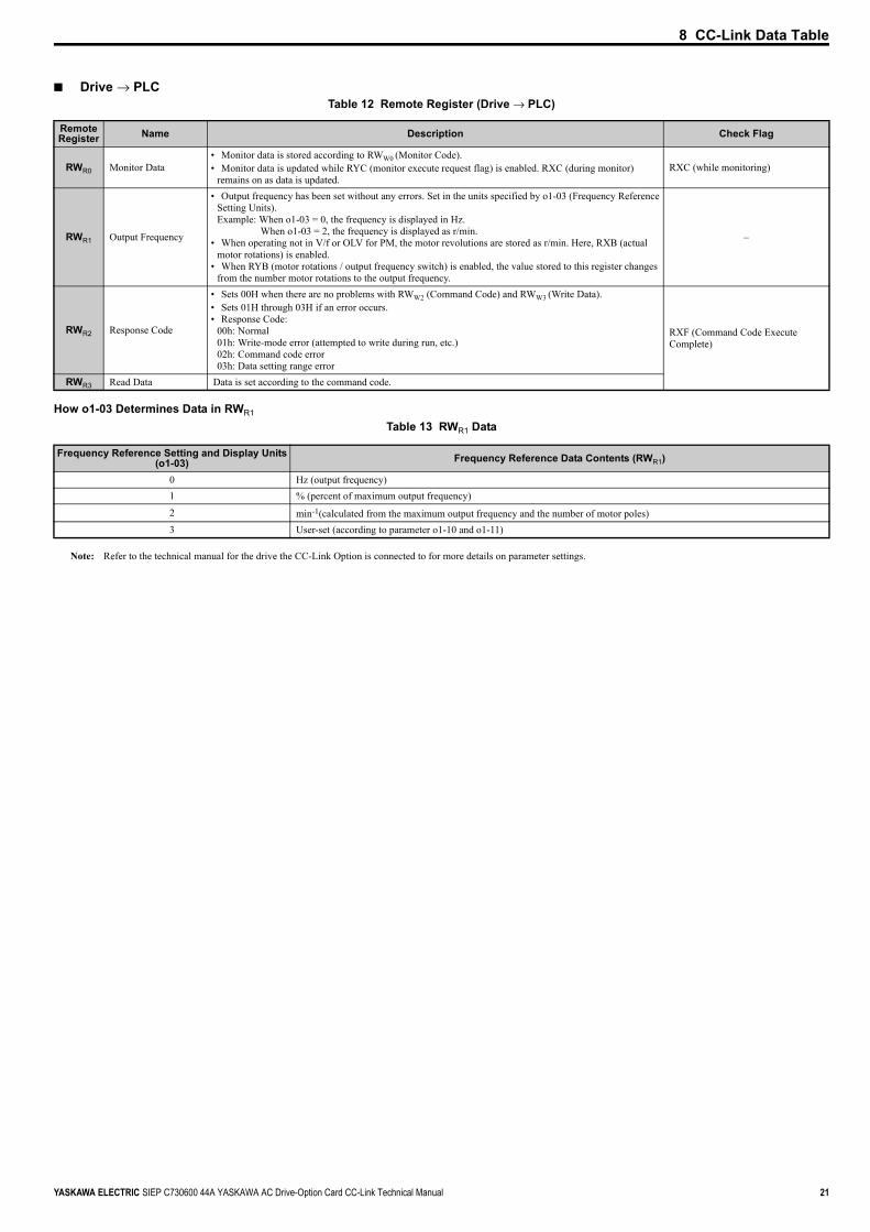
■ Drive → PLCTable 12 Remote Register (Drive → PLC)
How o1-03 Determines Data in RWR1
Table 13 RWR1 Data
Note: Refer to the technical manual for the drive the CC-Link Option is connected to for more details on parameter settings.
Remote Register Name Description Check Flag
RWR0 Monitor Data• Monitor data is stored according to RWW0 (Monitor Code).• Monitor data is updated while RYC (monitor execute request flag) is enabled. RXC (during monitor)
remains on as data is updated.RXC (while monitoring)
RWR1 Output Frequency
• Output frequency has been set without any errors. Set in the units specified by o1-03 (Frequency Reference Setting Units).Example: When o1-03 = 0, the frequency is displayed in Hz. When o1-03 = 2, the frequency is displayed as r/min.
• When operating not in V/f or OLV for PM, the motor revolutions are stored as r/min. Here, RXB (actual motor rotations) is enabled.
• When RYB (motor rotations / output frequency switch) is enabled, the value stored to this register changes from the number motor rotations to the output frequency.
–
RWR2 Response Code
• Sets 00H when there are no problems with RWW2 (Command Code) and RWW3 (Write Data).• Sets 01H through 03H if an error occurs.• Response Code:
00h: Normal01h: Write-mode error (attempted to write during run, etc.)02h: Command code error03h: Data setting range error
RXF (Command Code Execute Complete)
RWR3 Read Data Data is set according to the command code.
Frequency Reference Setting and Display Units(o1-03) Frequency Reference Data Contents (RWR1)
0 Hz (output frequency)1 % (percent of maximum output frequency)
2 min-1(calculated from the maximum output frequency and the number of motor poles)3 User-set (according to parameter o1-10 and o1-11)
22 YASKAWA ELECTRIC SIEP C730600 44A YASKAWA AC Drive-Option Card CC-Link Technical Manual
9 Troubleshooting
9 Troubleshooting
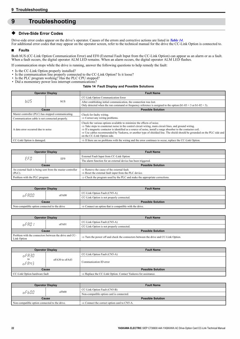
◆ Drive-Side Error CodesDrive-side error codes appear on the drive’s operator. Causes of the errors and corrective actions are listed in Table 14.For additional error codes that may appear on the operator screen, refer to the technical manual for the drive the CC-Link Option is connected to.
■ FaultsBoth bUS (CC-Link Option Communication Error) and EF0 (External Fault Input from the CC-Link Option) can appear as an alarm or as a fault. When a fault occurs, the digital operator ALM LED remains. When an alarm occurs, the digital operator ALM LED flashes.If communication stops while the drive is running, answer the following questions to help remedy the fault:• Is the CC-Link Option properly installed?• Is the communication line properly connected to the CC-Link Option? Is it loose?• Is the PLC program working? Has the PLC CPU stopped?• Did a momentary power loss interrupt communications?
Table 14 Fault Display and Possible Solutions
Operator Display Fault Name
bUSCC-Link Option Communication ErrorAfter establishing initial communication, the connection was lost.Only detected when the run command or frequency reference is assigned to the option (b1-03 = 3 or b1-02 = 3).
Cause Possible SolutionMaster controller (PLC) has stopped communicating. Check for faulty wiring.
⇒ Correct any wiring problems.Communication cable is not connected properly.
A data error occurred due to noise
Check the various options available to minimize the effects of noise.⇒ Take steps to counteract noise in the control circuit wiring, main circuit lines, and ground wiring.⇒ If a magnetic contactor is identified as a source of noise, install a surge absorber to the contactor coil. ⇒ Use cables recommended by Yaskawa, or another type of shielded line. The shield should be grounded on the PLC side and on the CC-Link Option side.
CC-Link Option is damaged. ⇒ If there are no problems with the wiring and the error continues to occur, replace the CC-Link Option.
Operator Display Fault Name
EF0External Fault Input from CC-Link OptionThe alarm function for an external device has been triggered.
Cause Possible SolutionAn external fault is being sent from the master controller (PLC).
⇒ Remove the cause of the external fault.⇒ Reset the external fault input from the PLC device.
Problem with the PLC program ⇒ Check the program used by the PLC and make the appropriate corrections.
Operator Display Fault Name
oFA00CC-Link Option Fault (CN5-A)CC-Link Option is not properly connected.
Cause Possible SolutionNon-compatible option connected to the drive ⇒ Connect an option that is compatible with the drive.
Operator Display Fault Name
oFA01CC-Link Option Fault (CN5-A)CC-Link Option is not properly connected.
Cause Possible SolutionProblem with the connectors between the drive and CC-Link Option ⇒ Turn the power off and check the connectors between the drive and CC-Link Option.
Operator Display Fault Name
to oFA30 to oFA43
CC-Link Option Fault (CN5-A)
Communication ID error
Cause Possible SolutionCC-Link Option hardware fault ⇒ Replace the CC-Link Option. Contact Yaskawa for assistance.
Operator Display Fault Name
oFb00CC-Link Option Fault (CN5-B)Non-compatible option card is connected.
Cause Possible SolutionNon-compatible option connected to the drive. ⇒ Connect the correct option card to CN5-A.
9 Troubleshooting
YASKAWA ELECTRIC SIEP C730600 44A YASKAWA AC Drive-Option Card CC-Link Technical Manual 23
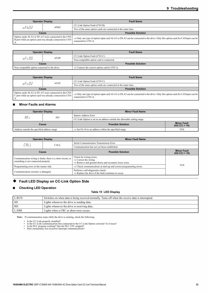
■ Minor Faults and Alarms
◆ Fault LED Display on CC-Link Option Side
■ Checking LED OperationTable 15 LED Display
Note: If communication stops while the drive is running, check the following:
• Is the CC-Link properly installed?• Is the CC-Link communication line connected to the CC-Link Option correctly? Is it loose?• Is the PLC program working? Has the PLC CPU stopped?• Did a momentary loss in power interrupt communications?
Operator Display Fault Name
oFb02CC-Link Option Fault (CN5-B)Two of the same option cards are connected at the same time.
Cause Possible SolutionOption cards AI-A3 or D1-A3 were connected to the CN5-B port while an option card was already connected to CN5-A.
⇒ Only one type of option input card AI-A3 or DI-A3 can be connected to the drive. Only this option card for CANopen can be connected to CN5-A.
Operator Display Fault Name
oFc00CC-Link Option Fault (CN5-C)Non-compatible option card is connected.
Cause Possible SolutionNon-compatible option connected to the drive. ⇒ Connect the correct option card to CN5-A.
Operator Display Fault Name
oFc02CC-Link Option Fault (CN5-C)Two of the same option cards are connected at the same time.
Cause Possible SolutionOption cards AI-A3 or D1-A3 were connected to the CN5-C port while an option card was already connected to CN5-A.
⇒ Only one type of option input card AI-A3 or DI-A3 can be connected to the drive. Only this option card for CANopen can be connected to CN5-A.
Operator Display Minor Fault Name
AErStation Address ErrorCC-Link Option is set to an address outside the allowable setting range.
Cause Possible Solution Minor Fault (H2- = 10)
Address outside the specified address range ⇒ Set F6-10 to an address within the specified range. YES
Operator Display Minor Fault Name
CALLSerial Communication Transmission ErrorCommunication has not yet been established.
Cause Possible Solution Minor Fault (H2- = 10)
Communication wiring is faulty, there is a short circuit, or something is not connected properly.
Check for wiring errors.⇒ Correct the wiring.⇒ Remove and ground shorts and reconnect loose wires.
YESProgramming error on the master side ⇒ Check communications at start-up and correct programming errors.
Communication circuitry is damaged. Perform a self-diagnostics check.⇒ Replace the drive if the fault continues to occur.
L.RUN Switches on when data is being received normally. Turns off when the receive data is interrupted.SD Lights whenever the drive is sending data.RD Lights whenever the drive is receiving data.L.ERR Lights when a CRC or abort error occurs.

9 Troubleshooting
24 YASKAWA ELECTRIC SIEP C730600 44A YASKAWA AC Drive-Option Card CC-Link Technical Manual
■ Faults that Occur with a Single DriveThe example below demonstrates how to read the LED display on the front cover of the drive to determine the cause of a fault and corrective action.Figure 11
Figure 11 Connecting a Single Drive
Table 16 LED Fault Display for CC-Link Option with a Single Drive
Note: SD and RD may appear to flash with slower baud rates.
: On / : Flashing / ×: Off / ∗: Either on or off
L.RUN SD RD L.ERR Cause Possible Solution
× Normal communications –
Error has occurred but communication is normal ⇒Remove the source of noise interference.
× Problem with the hardware ⇒Try cycling the power.Replace the CC-Link Option if the problem continues.
× × Problem with the hardware ⇒Try cycling the power.Replace the CC-Link Option if the problem continues.
× CRC error with the data received, and no response can be sent ⇒Remove the source of noise interference.
× × No station address received ⇒Check the PLC program and the operation where the problem occurred.
× × Problem with the hardware ⇒Try cycling the power.Replace the CC-Link Option if the problem continues.
× × × Problem with the hardware ⇒Try cycling the power.Replace the CC-Link Option if the problem continues.
× A response was received after polling, but a CRC error occurred when the reflex data was checked ⇒Remove the source of noise interference.
× × Problem with the hardware⇒Try cycling the power.Replace the CC-Link Option if the problem continues. ⇒See if the master device is actually set to function as a remote device station.
× × Problem with the hardware ⇒Try cycling the power.Replace the CC-Link Option if the problem continues.
× × × Problem with the hardware ⇒Try cycling the power.Replace the CC-Link Option if the problem continues.
× × CRC errors occurs when the station address is checked. ⇒Remove the source of noise interference.
× × × • No station address• Cannot receive station address due to noise interference ⇒Remove the source of noise interference.
× × × Problem with the hardware ⇒Try cycling the power.Replace the CC-Link Option if the problem continues.
× × × × Data cannot be received (CC-Link communications cable may be disconnected) ⇒Check the wiring.
× × ∗ The station address or communications speed is set incorrectly ⇒Enter the proper settings and cycle power.
The station address or communications speed was changed without cycling power afterwards.
⇒Return any incorrect settings to their original values and cycle power.⇒Enter the proper settings and cycle power.
Powersupply CPU Master
device
Station 1DRIVE
CC-LinkOption
9 Troubleshooting
YASKAWA ELECTRIC SIEP C730600 44A YASKAWA AC Drive-Option Card CC-Link Technical Manual 25
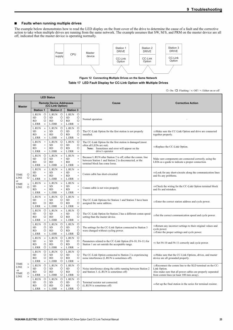
■ Faults when running multiple drivesThe example below demonstrates how to read the LED display on the front cover of the drive to determine the cause of a fault and the corrective action to take when multiple drives are running from the same network. The example assumes that SW, M/S, and PRM on the master device are all off, indicated that the master device is operating normally.Figure 12
Figure 12 Connecting Multiple Drives on the Same Network
Table 17 LED Fault Display for CC-Link Option with Multiple Drives
: On / : Flashing / ×: Off / ∗: Either on or off
LED Status
Cause Corrective ActionMaster
Remote Device Addresses (CC-Link Option)
Station 1 Station 2 Station 3
TIMELINEorTIME ×LINE
L.RUNSDRDL.ERR ×
L.RUNSDRDL.ERR ×
L.RUNSDRDL.ERR ×
Normal operation –
L.RUN ×SD ×RD ×L.ERR ×
L.RUNSDRDL.ERR ×
L.RUNSDRDL.ERR ×
The CC-Link Option for the first station is not properly installed.
⇒Make sure the CC-Link Option and drive are connected together properly.
L.RUN ∗SD ∗RD ∗L.ERR ∗
L.RUNSDRDL.ERR ×
L.RUNSDRDL.ERR ×
The CC-Link Option for the first station is damaged (most often all LEDs are out).
Note: Sometimes and error will appear on the drive’s operator
⇒Replace the CC-Link Option.
L.RUNSDRDL.ERR ×
L.RUN ×SD ∗RD ∗L.ERR ×
L.RUN ×SD ∗RD ∗L.ERR ×
Because L.RUN after Station 2 is off, either the comm. line between Station 1 and Station 2 is disconnected, or the terminal block has come loose.
Make sure components are connected correctly, using the LEDs as a guide to indicate a proper connection.
L.RUN ×SD ∗RD ∗L.ERR ×
L.RUN ×SD ∗RD ∗L.ERR ×
L.RUN ×SD ∗RD ∗L.ERR ×
Comm cable has short-circuited ⇒Look for any short-circuits along the communication lines and fix any problems.
L.RUN ×SD ∗RD ∗L.ERR ∗
L.RUN ×SD ∗RD ∗L.ERR ∗
L.RUN ×SD ∗RD ∗L.ERR ∗
Comm cable is not wire properly ⇒Check the wiring for the CC-Link Option terminal block and fix and mistakes.
L.RUN ×SD ∗RDL.ERR ×
L.RUNSDRDL.ERR ×
L.RUN ×SD ∗RDL.ERR ×
The CC-Link Options for Station 1 and Station 3 have been assigned the same address. ⇒Enter the correct station address and cycle power.
L.RUNSDRDL.ERR ×
L.RUN ×SD ×RDL.ERR ×
L.RUNSDRDL.ERR ×
The CC-Link Option for Station 2 has a different comm speed setting than the master device. ⇒Set the correct communication speed and cycle power.
L.RUNSDRDL.ERR ×
L.RUNSDRDL.ERR ×
L.RUNSDRDL.ERR
The settings for the CC-Link Option connected to Station 3 were changed without cycling power.
⇒Return any incorrect settings to their original values and cycle power.⇒Enter the proper settings and cycle power.
L.RUN ×SD ×RDL.ERR
L.RUNSDRDL.ERR ×
L.RUNSDRDL.ERR ×
Parameters related to the CC-Link Option (F6-10, F6-11) for Station 1 are set outside the acceptable range. ⇒ Set F6-10 and F6-11 correctly and cycle power.
TIME ×LINE × or TIMELINE ×
L.RUNSDRDL.ERR ×
L.RUNSDRDL.ERR
L.RUNSDRDL.ERR ×
The CC-Link Option connected to Station 2 is experiencing noise interference (L.RUN is sometimes off).
⇒Make sure that the CC-Link Options, drives, and master device are all grounded properly.
L.RUNSDRDL.ERR ×
L.RUNSDRDL.ERR
L.RUNSDRDL.ERR
Noise interference along the cable running between Station 2 and Station 3. (L.RUN is sometimes off)
⇒Reconnect the comm line to the SLD terminal on the CC-Link Option.Also make sure that all power cables are properly separated from comm lines (at least 100 mm away).
L.RUNSDRDL.ERR ×
L.RUNSDRDL.ERR ×
L.RUNSDRDL.ERR
Terminal resistor not connected.(L.RUN is sometimes off) ⇒Set up the final station in the series for terminal resistor.
Powersupply CPU Master
device
Station 1DRIVE
Station 2DRIVE
Station 3DRIVE
CC-LinkOption
CC-LinkOption
CC-LinkOption

26 YASKAWA ELECTRIC SIEP C730600 44A YASKAWA AC Drive-Option Card CC-Link Technical Manual
10 CC-Link Code Numbers
10 CC-Link Code Numbers
◆ Command CodesTable 18 Command Codes
Command Code Name Description
1181H Read Run command source
0: Operator1: Control circuit terminals (sequencer input)2: MEMOBUS communications3: Option card
1180H Read frequency reference source
0: Operator1: Control circuit terminals (analog input)2: MEMOBUS communications3: Option card4: Pulse train input
2181H Write Run command source
0: Operator1: Control circuit terminals (sequencer input)2: MEMOBUS communications3: Option card
2180H Write frequency reference source
0: Operator1: Control circuit terminals (analog input)2: MEMOBUS communications3: Option card4: Pulse train input
0074H Fault History 1 Reads the contents from U3-01.0075H Fault History 2 Reads the contents from U3-02.0076H Fault History 3 Reads the contents from U3-03.0077H Fault History 4 Reads the contents from U3-04.0078H Fault History 5 Reads the contents from U3-05.0079H Fault History 6 Reads the contents from U3-06.007AH Fault History 7 Reads the contents from U3-07.0080H Fault History 8 Reads the contents from U3-08.0081H Fault History 9 Reads the contents from U3-09.0082H Fault History 10 Reads the contents from U3-10.006DH Read frequency reference (RAM) Reads the drive’s frequency reference from RAM.006EH Read frequency reference (EEPROM) Reads the frequency reference from EEPROM.
007BH Read LOCAL/REMOTE status0: 0 = Frequency reference is supplied by CC-Link.1: 0 = FWD/REV Run command is supplied by CC-Link.8: 1 = During Stall Prevention.
00FBH Write LOCAL/REMOTE status
0: 0 = Frequency reference from CC-Link is enabled.1: 0 = FWD/REV Run command from CC-Link is enabled.When power is cycled, however, the source is determined by parameters b1-01 and b1-02.If one of the multi-function relay input terminals is set to switch the source of the Run command (H1- = 2), then the Run command and frequency reference will be supplied by parameters b1-15 and b1-16 when that terminal is closed.
00EDH Write frequency reference (RAM) Writes the frequency reference for the drive to RAM.00EEH Write frequency reference (EEPROM) Writes the frequency reference and all parameter values to EEPROM.
– Read parameters Adds 1000H to the MEMOBUS register number.
– Parameter settings Master executes commands by adding 2000H to the MEMOBUS register number. Conversion takes place on the option card side.
00F4H Clear all fault contents 9696H: Clear fault history00FDH Reset drive 9696H: Fault reset

10 CC-Link Code Numbers
YASKAWA ELECTRIC SIEP C730600 44A YASKAWA AC Drive-Option Card CC-Link Technical Manual 27
◆ Extended Command CodesTable 19 Extended Command Codes
Command Code NameRead Write BIT
100H –
Operation signals
0 H5-12 = 0: Forward run command (0 = Stop, 1 = Forward run)H5-12 = 1: Run command (0 = Stop, 1 = Run)
1 H5-12 = 0: Reverse run command (0 = Stop, 1 = Reverse run)H5-12 = 1: Forward/Reverse (0 = Forward, 1 = Reverse)
2 External fault (EF0)3 Fault reset
4 Multi-function input 1Bit disabled when H1-01 = 40 (FWD/Stop)
5 Multi-function input 2Bit disabled when H1-02 = 41 (REV/Stop)
6 Multi-function input 37 Multi-function input 48 Multi-function input 59 Multi-function input 6A Multi-function input 7B Multi-function input 8
C to F Reserved101H – Frequency reference (RAM)102H 202H Torque reference / torque limit103H 203H Torque compensation104H 204H PID setpoint105H 205H Multi-function analog monitor output terminal 1106H 206H Multi-function analog monitor output terminal 2
107H 207H
Multi-function relay output
0 Multi-Function Contact Outputs (terminal M1-M2) 1 : ON 0 : OFF
1 Multi-Function Photocoupler Output 1 (terminal P1-PC) 1 : ON 0 : OFF
2 Multi-Function Photocoupler Output 2 (terminal P2-PC) 1 : ON 0 : OFF3-5 Reserved6 1 : Bit 7 function enabled
7 1 : Fault Contact Output (terminal MA/MB-MC) 1 : ON 0 : OFF8-F Reserved
109H 209H Pulse output10FH 20FH V/f gain
110H –
Status signal0 During run1 During zero speed2 During reverse3 During fault reset signal input4 During speed agree5 Drive Ready6 Alarm7 Fault8 During operation error (oPE )9 During Momentary power lossA NetCtrl statusB Multi-function contact output (terminal M1-M2)C Multi-function photocoupler output 1 (terminal P1 - PC)D Multi-function photocoupler output 2 (terminal P2 - PC)E Motor 2 selectedF Zero servo complete
111H – Speed restore112H – Through-mode113H – Number of pulse 1 speed detection114H – Frequency reference115H – Output frequency116H – Output current117H – Analog input terminal A1118H – DC bus voltage11CH – Analog input terminal A211DH – Sequence input
11EH – Analog input terminal A3

10 CC-Link Code Numbers
28 YASKAWA ELECTRIC SIEP C730600 44A YASKAWA AC Drive-Option Card CC-Link Technical Manual
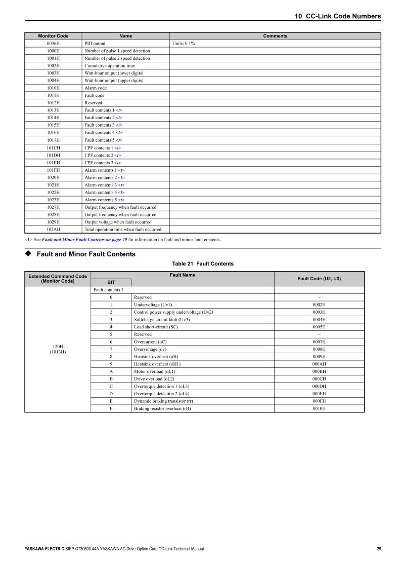
◆ Monitor CodesTable 20 Monitor Codes
11FH – Number of pulse 2 speed detection
120H – Fault contents 1 <1>
121H – Fault contents 2 <1>
122H – Fault contents 3 <1>
123H – Fault contents 4 <1>
124H – Fault contents 5 <1>
130H – CPF contents 1 <1>
131H – CPF contents 2 <1>
132H – CPF contents 3 <1> <1> See Fault and Minor Fault Contents on page 29 for information on fault contents.
Monitor Code Name Comments0000H Reserved0001H Output frequency Units are determined by o1-03.0002H Output current Units are either 0.1 A or 0.01 A, depending on the capacity of the drive.0003H Output voltage reference Units: 0.1 V0004H Reserved0005H Frequency reference Units are determined by o1-03.0006H Motor speed Units: 1 r/min0007H Motor torque Units: 0.1%0008H DC bus voltage Units: 1 V0009H Reserved000AH Reserved000BH Reserved000CH Reserved000DH Reserved000EH Output power Units: 0.1 kW
000FH Input terminal status
0010H Output terminal status
0011H Reserved0012H Motor excitation current Units: 0.1%0013H Reserved
0014H Cumulative operation time• Units: 1 hour• Parameter o4-02 determines if the operation time is the considered to be whenever the drive powered on or
only when there is voltage output.0015H Reserved0016H Reserved
0017H Actual operation time• Units: 1 hour• Parameter o4-02 determines if the operation time is the considered to be whenever the drive powered on or
only when there is voltage output.0018H Motor secondary current0019H Cumulative power Units: 4 kW0034H PID setpoint Units: 0.1%0035H PID input Units: 0.1%
Command Code NameRead Write BIT
7 6 5 4 3 2 1 0
Multi-Function Digital Input 1 (terminal S1 enabled)
Multi-Function Digital Input 2 (terminal S2 enabled)
Multi-Function Digital Input 3 (terminal S3 enabled)
Multi-Function Digital Input 4 (terminal S4 enabled)
Multi-Function Digital Input 5 (terminal S5 enabled)
Multi-Function Digital Input 6 (terminal S6 enabled)
Multi-Function Digital Input 7 (terminal S7 enabled)
Multi-Function Digital Input 8 (terminal S8 enabled)
1: ONRW 0: OFF
7 6 5 4 3 2 1 0
Multi-Function Digital Output (terminal M1-M2) enabled
Multi-Function Digital Output 1 (terminal P1) enabled
Multi-Function Digital Output 2 (terminal P2) enabled
Fault Contact Output (terminal MA/MB-MC) enabled
1: ONRW 0: OFF
Not used
10 CC-Link Code Numbers
YASKAWA ELECTRIC SIEP C730600 44A YASKAWA AC Drive-Option Card CC-Link Technical Manual 29
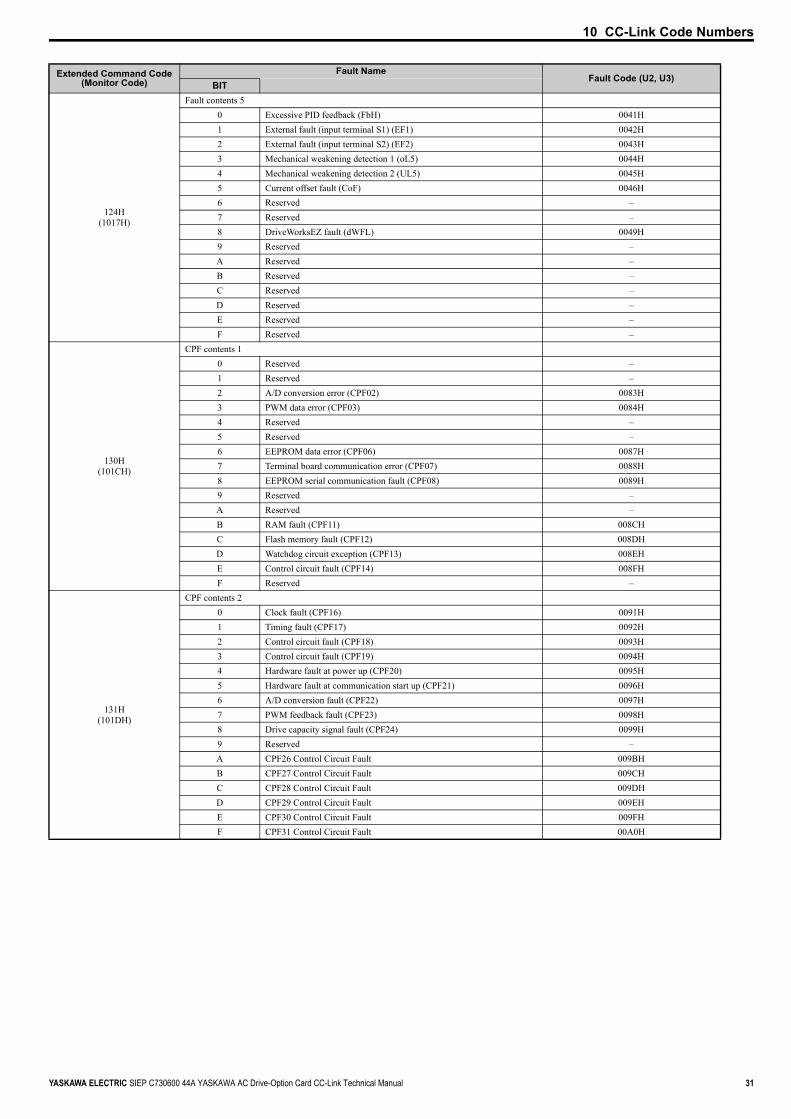
◆ Fault and Minor Fault ContentsTable 21 Fault Contents
0036H PID output Units: 0.1%1000H Number of pulse 1 speed detection1001H Number of pulse 2 speed detection1002H Cumulative operation time1003H Watt-hour output (lower digits)1004H Watt-hour output (upper digits)1010H Alarm code1011H Fault code1012H Reserved1013H Fault contents 1 <1>
1014H Fault contents 2 <1>
1015H Fault contents 3 <1>
1016H Fault contents 4 <1>
1017H Fault contents 5 <1>
101CH CPF contents 1 <1>
101DH CPF contents 2 <1>
101EH CPF contents 3 <1>
101FH Alarm contents 1 <1>
1020H Alarm contents 2 <1>
1021H Alarm contents 3 <1>
1022H Alarm contents 4 <1>
1023H Alarm contents 5 <1>
1027H Output frequency when fault occurred1028H Output frequency when fault occurred1029H Output voltage when fault occurred102AH Total operation time when fault occurred
<1> See Fault and Minor Fault Contents on page 29 for information on fault and minor fault contents.
Extended Command Code(Monitor Code)
Fault NameFault Code (U2, U3)
BIT
120H(1013H)
Fault contents 10 Reserved –1 Undervoltage (Uv1) 0002H2 Control power supply undervoltage (Uv2) 0003H3 Softcharge circuit fault (Uv3) 0004H4 Load short-circuit (SC) 0005H5 Reserved –6 Overcurrent (oC) 0007H7 Overvoltage (ov) 0008H8 Heatsink overheat (oH) 0009H9 Heatsink overheat (oH1) 000AHA Motor overload (oL1) 000BHB Drive overload (oL2) 000CHC Overtorque detection 1 (oL3) 000DHD Overtorque detection 2 (oL4) 000EHE Dynamic braking transistor (rr) 000FHF Braking resistor overheat (rH) 0010H
Monitor Code Name Comments

10 CC-Link Code Numbers
30 YASKAWA ELECTRIC SIEP C730600 44A YASKAWA AC Drive-Option Card CC-Link Technical Manual
121H(1014H)
Fault contents 20 External fault (input terminal S3) (EF3) 0011H1 External fault (input terminal S4) (EF4) 0012H2 External fault (input terminal S5) (EF5) 0013H3 External fault (input terminal S6) (EF6) 0014H4 External fault (input terminal S7) (EF7) 0015H5 External fault (input terminal S8) (EF8) 0016H6 Reserved –
7 Overspeed (oS)Note: Possible only when using Simple V/f with PG 0018H
8 Excessive speed deviation (dEv)Note: Possible only when using Simple V/f with PG 0019H
9 PG disconnect (PGo)Note: Possible only when using Simple V/f with PG 001AH
A Input phase loss (PF) 001BHB Output phase loss (LF) 001CHC Motor overheat (PTC input) (oH3) 001DHD Digital operator connection fault (oPr) 001EHE EEPROM write error (Err) 001FHF Motor overheat fault (PTC input) (oH4) 0020H
122H(1015H)
Fault contents 30 MEMOBUS communication fault (CE) 0021H1 Option communications error (bUS) 0022H2 Reserved –3 Reserved –4 Control fault (CF) 0025H5 Zero servo fault (SvE) 0026H6 Option card external fault (EF0) 0027H7 PID feedback loss (FbL) 0028H8 Undertorque detection 1 (UL3) 0029H9 Undertorque detection 2 (UL4) 002AHA High Slip Braking overload (oL7) 002BHB Reserved –C Reserved –D Reserved –E Reserved –F Hardware fault (including oFx) 0030H
123H(1016H)
Fault contents 40 Reserved –1 Z-phase pulse fall detection (Only IPM mode with PG) 0032H2 Z-phase noise fault detection (Only IPM mode with PG) 0033H3 Inversion detection (Only IPM mode with PG) 0034H4 Inversion prevention detection (Only IPM mode with PG) 0035H5 Output current imbalance (LF2) 0036H6 Pullout detection (STo) 0037H7 PG fault (PGoH) –8 Reserved –9 Reserved –A Too many speed search restart (SEr) 003BHB Reserved –C voF Output Voltage Detection Fault 004DHD rF Braking Resistor Fault 004EHE boL Braking Transistor Overload Fault 004FHF Reserved –
Extended Command Code(Monitor Code)
Fault NameFault Code (U2, U3)
BIT
10 CC-Link Code Numbers
YASKAWA ELECTRIC SIEP C730600 44A YASKAWA AC Drive-Option Card CC-Link Technical Manual 31
124H(1017H)
Fault contents 50 Excessive PID feedback (FbH) 0041H1 External fault (input terminal S1) (EF1) 0042H2 External fault (input terminal S2) (EF2) 0043H3 Mechanical weakening detection 1 (oL5) 0044H4 Mechanical weakening detection 2 (UL5) 0045H5 Current offset fault (CoF) 0046H6 Reserved –7 Reserved –8 DriveWorksEZ fault (dWFL) 0049H9 Reserved –A Reserved –B Reserved –C Reserved –D Reserved –E Reserved –F Reserved –
130H(101CH)
CPF contents 10 Reserved –1 Reserved –2 A/D conversion error (CPF02) 0083H3 PWM data error (CPF03) 0084H4 Reserved –5 Reserved –6 EEPROM data error (CPF06) 0087H7 Terminal board communication error (CPF07) 0088H8 EEPROM serial communication fault (CPF08) 0089H9 Reserved –A Reserved –B RAM fault (CPF11) 008CHC Flash memory fault (CPF12) 008DHD Watchdog circuit exception (CPF13) 008EHE Control circuit fault (CPF14) 008FHF Reserved –
131H(101DH)
CPF contents 20 Clock fault (CPF16) 0091H1 Timing fault (CPF17) 0092H2 Control circuit fault (CPF18) 0093H3 Control circuit fault (CPF19) 0094H4 Hardware fault at power up (CPF20) 0095H5 Hardware fault at communication start up (CPF21) 0096H6 A/D conversion fault (CPF22) 0097H7 PWM feedback fault (CPF23) 0098H8 Drive capacity signal fault (CPF24) 0099H9 Reserved –A CPF26 Control Circuit Fault 009BHB CPF27 Control Circuit Fault 009CHC CPF28 Control Circuit Fault 009DHD CPF29 Control Circuit Fault 009EHE CPF30 Control Circuit Fault 009FHF CPF31 Control Circuit Fault 00A0H
Extended Command Code(Monitor Code)
Fault NameFault Code (U2, U3)
BIT

10 CC-Link Code Numbers
32 YASKAWA ELECTRIC SIEP C730600 44A YASKAWA AC Drive-Option Card CC-Link Technical Manual
Table 22 Minor Fault Contents
132H (101EH)
CPF contents 3 0 CPF32 Control Circuit Fault 00A1H1 CPF33 Control Circuit Fault 00A2H2 CPF34 Control Circuit Fault 00A3H3 Reserved –4 Reserved –5 Reserved –6 Reserved –7 Reserved –8 Reserved –9 Reserved –A Reserved –B Reserved –C Reserved –D Reserved –E Reserved –F Reserved –
Monitor CodeMinor Fault Name Minor Fault Code
(MEMOBUS Register 07FH)BIT
101FH
Minor fault contents 10 Undervoltage (Uv) 0001H1 Overvoltage (ov) 0002H2 Heatsink Overheat (oH) 0003H3 Drive Overheat (oH2) 0004H4 Overtorque 1 (oL3) 0005H5 Overtorque 2 (oL4) 0006H6 Run Command Input Error (EF) 0007h7 Drive Baseblock (bb) 0008H8 External Fault (input terminal S3) (EF3) 0009H9 External Fault (input terminal S4) (EF4) 000AHA External Fault (input terminal S5) (EF5) 000BHB External Fault (input terminal S6) (EF6) 000CHC External Fault (input terminal S7) (EF7) 000DHD External Fault (input terminal S8) (EF8) 000EHE Reserved –F Overspeed (oS) 0010H
1020H
Minor fault contents 20 Excessive Speed Deviation (dEv) 0011H1 PG Disconnect (PGo) 0012H2 Operator Connection Fault (oPr) 0013H3 MEMOBUS/Modbus Communication Error (CE) 0014H4 Option Card Communications Error (bUS) 0015H5 Serial Communication Transmission Error (CALL) 0016H6 Motor Overload (oL1) 0017H7 Drive Overload (oL2) 0018H8 Reserved –9 Option Card External Fault (EF0) 001AHA During Run 2, Motor Switch Command Input (rUn) 001BHB Reserved –C Serial Communication Transmission Error (CALL) 001DHD Undertorque Detection 1 (UL3) 001EHE Undertorque Detection 2 (UL4) 001FHF MEMOBUS/Modbus Test Mode Fault (SE) 0020H
Extended Command Code(Monitor Code)
Fault NameFault Code (U2, U3)
BIT

10 CC-Link Code Numbers
YASKAWA ELECTRIC SIEP C730600 44A YASKAWA AC Drive-Option Card CC-Link Technical Manual 33
1021H
Minor fault contents 30 Reserved –1 Motor Overheat (oH3) 0022H2 Reserved –3 Reserved –4 Reserved –5 Reserved –6 PID Feedback Loss (FbL) 0027H7 Excessive PID Feedback (FbH) 0028H8 Reserved –9 Drive Disabled (dnE) 002AHA PG Hardware Fault (PGoH) 002BHB Reserved –C Reserved –D Reserved –E Reserved –F Reserved –
1022H
Minor fault contents 4 –0 Reserved 1 Station Number Setting Error (AEr) 0032H2 Reserved –3 Current Alarm (HCA) 0034H4 Cooling Fan Maintenance Time (LT-1) 0035H5 Capacitor Maintenance Time (LT-2) 0036H6 Reserved –7 Reserved –8 External Fault (input terminal S1) (EF1) 0039H9 External Fault (input terminal S2) (EF2) 003AHA Safe Disable Signal Input (HbbF) 003BHB Safe Disable Signal Input (Hbb) 003CHC Mechanical Weakening Detection 1 (oL5) 003DHD Mechanical Weakening Detection 2 (UL5) 003EHE Reserved –F Reserved –
1023H
Minor fault contents 5 –0 Output Voltage Detection Fault (voF) 0041H1 IGBT Maintenance Time (90%) (TrPC) 0042H2 Soft Charge Bypass Relay Maintenance Time (LT-3) 0043H3 IGBT Maintenance Time (50%) (LT-4) 0044H4 Braking Transistor Overload Fault (boL) 0045H5 Reserved –6 Reserved –7 Reserved –8 DriveWorksEZ Alarm (dWAL) 0049H9 Reserved –A Reserved –B Reserved –C Reserved –D Reserved –E Reserved –F Reserved –
Monitor CodeMinor Fault Name Minor Fault Code
(MEMOBUS Register 07FH)BIT
34 YASKAWA ELECTRIC SIEP C730600 44A YASKAWA AC Drive-Option Card CC-Link Technical Manual
11 Specifications
11 Specifications
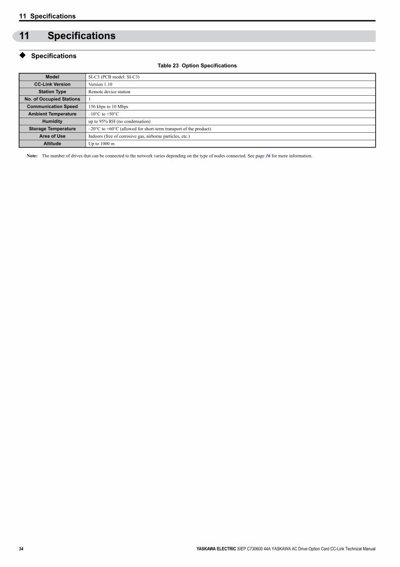
◆ SpecificationsTable 23 Option Specifications
Note: The number of drives that can be connected to the network varies depending on the type of nodes connected. See page 16 for more information.
Model SI-C3 (PCB model: SI-C3)CC-Link Version Version 1.10
Station Type Remote device stationNo. of Occupied Stations 1Communication Speed 156 kbps to 10 MbpsAmbient Temperature –10°C to +50°C
Humidity up to 95% RH (no condensation)Storage Temperature –20°C to +60°C (allowed for short-term transport of the product)
Area of Use Indoors (free of corrosive gas, airborne particles, etc.)Altitude Up to 1000 m
11 Specifications
YASKAWA ELECTRIC SIEP C730600 44A YASKAWA AC Drive-Option Card CC-Link Technical Manual 35
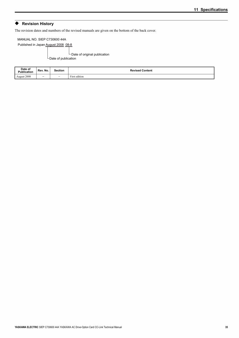
◆ Revision HistoryThe revision dates and numbers of the revised manuals are given on the bottom of the back cover.
Date of Publication Rev. No. Section Revised Content
August 2008 − − First edition
MANUAL NO. SIEP C730600 44APublished in Japan August 2008 08-8
Date of publicationDate of original publication

英文 No.4-5 (A4) メカトロ製品用
Technical ManualCC-LinkYASKAWA AC Drive-Option Card
YASKAWA ELECTRIC CORPORATION
In the event that the end user of this product is to be the military and said product is to be employed in any weapons systems or the manufacture thereof, the export will fall under the relevant regulations as stipulated in the Foreign Exchange and Foreign Trade Regulations. Therefore, be sure to follow all procedures and submit all relevant documentation according to any and all rules, regulations and laws that may apply.
Specifications are subject to change without notice for ongoing product modifications and improvements.
© 2008 YASKAWA ELECTRIC CORPORATION. All rights reserved.
YASKAWA
IRUMA BUSINESS CENTER (SOLUTION CENTER)480, Kamifujisawa, Iruma, Saitama 358-8555, JapanPhone 81-4-2962-5696 Fax 81-4-2962-6138
YASKAWA ELECTRIC AMERICA, INC.2121 Norman Drive South, Waukegan, IL 60085, U.S.A.Phone 1-847-887-7000 Fax 1-847-887-7370
YASKAWA ELETRICO DO BRASIL LTDA.Avenida Fagundes Filho, 620 Sao Paulo-SP CEP 04304-000, Brazil Phone 55-11-3585-1100 Fax 55-11-5581-8795
YASKAWA ELECTRIC EUROPE GmbHHauptstraβe 185, 65760 Eschborn, GermanyPhone 49-6196-569-300 Fax 49-6196-569-398
YASKAWA ELECTRIC UK LTD.1 Hunt Hill Orchardton Woods Cumbernauld, G68 9LF, United KingdomPhone 44-1236-735000 Fax 44-1236-458182
YASKAWA ELECTRIC KOREA CORPORATION7F, Doore Bldg. 24, Yeoido-dong, Youngdungpo-Ku, Seoul 150-877, KoreaPhone 82-2-784-7844 Fax 82-2-784-8495
YASKAWA ELECTRIC (SINGAPORE) PTE. LTD.151 Lorong Chuan, #04-01, New Tech Park 556741, SingaporePhone 65-6282-3003 Fax 65-6289-3003
YASKAWA ELECTRIC (SHANGHAI) CO., LTD.No.18 Xizang Zhong Road. Room 1702-1707, Harbour Ring Plaza Shanghai 200001, ChinaPhone 86-21-5385-2200 Fax 86-21-5385-3299
YASKAWA ELECTRIC (SHANGHAI) CO., LTD. BEIJING OFFICERoom 1011A, Tower W3 Oriental Plaza, No.1 East Chang An Ave.,Dong Cheng District, Beijing 100738, ChinaPhone 86-10-8518-4086 Fax 86-10-8518-4082
YASKAWA ELECTRIC TAIWAN CORPORATION9F, 16, Nanking E. Rd., Sec. 3, Taipei, TaiwanPhone 886-2-2502-5003 Fax 886-2-2505-1280
Published in Japan August 2008 08-8
MANUAL NO. SIEP C730600 44A
08-5-3