Embed Size (px)
Citation preview

YASKAWAMechatronics Solutions
SI-S1 Option Card for CANopen Instructions EZZ020072
Page 1 (35)
SI-S1 Option Card for CANopen Instructions
Issued date; 09/July/2004

YASKAWAMechatronics Solutions
SI-S1 Option Card for CANopen Instructions EZZ020072
Page 2 (35)
1 SI-S1 HARDWARE OVERVIEW ............................................................................................................... 5
1.1 Status LED’s........................................................................................................................................ 5
1.2 CANopen connector........................................................................................................................... 6
1.3 Node Address ..................................................................................................................................... 6
1.4 Baudrate .............................................................................................................................................. 6
2 ATTENTION FOR DSP 402 ...................................................................................................................... 7
3 INVERTER OBJECT LIST ........................................................................................................................ 8
3.1 Communication Objects .................................................................................................................... 8
3.2 Manufacturer specific Objects .......................................................................................................... 8
3.3 Drives and motion control ( DSP 402 ) ............................................................................................. 9 3.3.1 Common Entries ........................................................................................................................ 9 3.3.2 Device Control............................................................................................................................ 9 3.3.3 Velocity Mode............................................................................................................................. 9
4 OBJECT DESCRIPTION........................................................................................................................... 9
4.1 Communication Objects ( DSP 301 ) .............................................................................................. 10 4.1.1 Inverter Error List..................................................................................................................... 15
4.2 Manufacturer specific Objects ( DSP 301 ) .................................................................................... 18 4.2.1 Objects overview ..................................................................................................................... 18 4.2.2 Input Parameters...................................................................................................................... 18 4.2.2.1 Input data to inverter ............................................................................................................ 19 4.2.2.2 Operation Command ............................................................................................................ 19 4.2.2.3 Optional Input Object ........................................................................................................... 20 4.2.3 Output Parameters................................................................................................................... 20 4.2.3.1 Output data from inverter .................................................................................................... 20 4.2.3.2 Inverter Status....................................................................................................................... 20 4.2.4 Modbus data............................................................................................................................. 21 4.2.4.1 Memobus Read request ....................................................................................................... 21 4.2.4.2 Memobus Write Request...................................................................................................... 21 4.2.4.3 Memobus Enter Command Not Limited ............................................................................. 21 4.2.4.4 Memobus Enter Command Limited .................................................................................... 21 4.2.4.5 Memobus Read Response................................................................................................... 22 4.2.4.6 Memobus Write Response................................................................................................... 22 4.2.4.7 Memobus Enter Command Not Limited Response........................................................... 22 4.2.4.8 Optional Output Object ........................................................................................................ 22 4.2.4.9 Analogue Input Monitor ....................................................................................................... 22
4.3 Drives and motion control ( DSP 402 ) .......................................................................................... 24 4.3.1 Common entries....................................................................................................................... 24 4.3.1 Device control .......................................................................................................................... 26 4.3.1 Velocity Mode........................................................................................................................... 28
5 PDO MAPPING ....................................................................................................................................... 33

YASKAWAMechatronics Solutions
SI-S1 Option Card for CANopen Instructions EZZ020072
Page 3 (35)
5.1 Receive PDO ..................................................................................................................................... 33
5.2 Transmit PDO.................................................................................................................................... 34
6 RELATED E7,F7;G7 PARAMETERS..................................................................................................... 35
7 V7 RELATED PARAMETER................................................................................................................... 35

YASKAWAMechatronics Solutions
SI-S1 Option Card for CANopen Instructions EZZ020072
Page 4 (35)
INTRODUCTION This document describes the use of the CANopen option board (SI-S1) for YASKAWA inverter. It is intended to provide information necessary to start-up and use the board. The option card software is designed to fulfill following profiles: DS 301 COMMUNICATION PROFILE The device has passed the conformance test for the CANopen Communication Profile DS 301 ver. 4.02. DSP 402 DRIVES AND MOTION PROFILE In the drive the velocity mode is implemented according to DSP 402 ver. 1.1

YASKAWAMechatronics Solutions
1 SI-S1 Hardware overview
1.1 StThere awill be p Name Power WD (wa
NS (Ne
MS (Mo
atus LED’s re four status and indication LED’s on the option board. During start-up a LED test erformed to make sure the LED’s are working. Test sequence: Red - Green - Off.
Colour Function Green Indicates 5V power supply
tchdog) Green / Red Turned off: Option board CPU not running. Lit green: Initialization 1 Hz green: Normal operation 2 Hz green: Initialization phase Lit red: Internal option board error. 2 Hz red: Inverter ini failure firmware Other indication: Unspecified, option board error.
twork Status) Green / Red 1 Hz green: Bus off or error passive Lit green: Link OK, On-line, connected Lit red: Critical link failure.
dule Status) Green / Red Off: No bus connection ( ini phase ) 1Hz red: Bus initialization failed Lit green: Operational State 1 Hz green Pre Operational State 2 Hz green Stopped State
SI-S1 Option Card for CANopen Instructions EZZ020072
Page 5 (35)

YASKAWAMechatronics Solutions
SI-S1 Option Card for CANopen Instructions EZZ020072
Page 6 (35)
1.2 CANopen connector The CANopen network cables are connected to the option board via a screw connector. The pin layout for the connector is shown in the table below. Pin Name Function 1 CAN_GND CAN_GND 2 CAN_L CAN_L bus line (dominant low) 3 CAN_SHLD CAN shield (Optional) 4 CAN_H CAN_H bus line (dominant high)
1.3 Node Address The network node address is set via two rotary switches on the option board (ADDRESS_HIGH and ADDRESS_LOW). Possible node addresses are between 0 - 99 in decimal format. The address is calculated in the following way Address = (ADDRESS_HIGH * 10) + (ADDRESS_LOW * 1) NOTE: The node address can not be changed during operation.
1.4 Baudrate The baudrate is configured with one decimal rotary switch. See table below for supported baudrates.
Switch setting Baudrate 0 Not Available 1 10 kbit / s 2 20 kbit / s 3 50 kbit / s 4 125 kbit / s 5 250 kbit / s 6 500 kbit / s 7 800 kbit / s 8 1 Mbit / s 9 Not available
YASKAWAMechatronics Solutions
SI-S1 Option Card for CANopen Instructions EZZ020072
Page 7 (35)
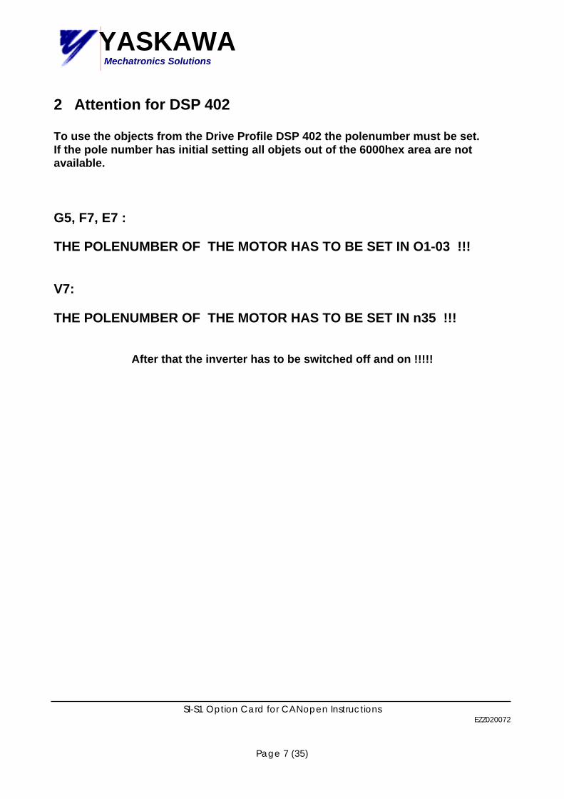
2 Attention for DSP 402 To use the objects from the Drive Profile DSP 402 the polenumber must be set. If the pole number has initial setting all objets out of the 6000hex area are not available. G5, F7, E7 : THE POLENUMBER OF THE MOTOR HAS TO BE SET IN O1-03 !!! V7: THE POLENUMBER OF THE MOTOR HAS TO BE SET IN n35 !!!
After that the inverter has to be switched off and on !!!!!

YASKAWAMechatronics Solutions
SI-S1 Option Card for CANopen Instructions EZZ020072
Page 8 (35)
3 Inverter Object List
3.1 Communication Objects
Index Object name Page 1000 Device Type 9 1001 Error Register 9 1003 Pre-defined Error Field 10 1005 COB-ID SYNC message 10 1008 Manufacturer Device Name 10 1009 Manufacturer Hardware Version 11 100A Manufacturer Software Version 11 100C Guard Time 11 100D Life Time Factor 12 100E Node Guarding Identifier 12 1010 Store parameters 12 1011 Restore default parameters 13 1014 COB-ID Emergency Object 13 1016 Consumer Heartbeat Time 13 1017 Producer Heartbeat Time 14 1018 Identity Object 14
3.2 Manufacturer specific Objects
Index Object name Page 2000 Operation Command 18 2010 Speed Command 18 2020 Torque Reference 18 2030 Torque Compensation 18 2040 Read Memobus Request 21 2050 Write Memobus Request 21 2060 Enter Command Not Limited 21 2070 Enter Command Limited 21 2080 Optional Input Object 18 2100 Inverter Status 19 2110 Output Frequency 19 2120 Output Current 19 2130 Output Torque 19 2140 Read Memobus Response 22 2150 Write Memobus Response 22 2160 Enter Not Limited Response 23 2180 Optional Output Object 23 2190 Analogue Input Monitor 23

YASKAWAMechatronics Solutions
SI-S1 Option Card for CANopen Instructions EZZ020072
Page 9 (35)
3.3 Drives and motion control ( DSP 402 )
3.3.1 Common Entries
Index Object name Page 60FD Digital Input 24 60FE Digital Output 25
3.3.2 Device Control
Index Object name Page 6040 Controlword 26 6041 Statusword 26 6060 Modes_of_operation 27 6061 Modes_of_operation_display 27
3.3.3 Velocity Mode
Index Object name Page 6042 vl_target_velocity 28 6043 vl_velocity_demand 28 6044 vl_control_effort 29 6046 vl_velocity_min_max_amount 29 6048 vl_velocity_acceleration 30 6049 vl_velocity_deceleration 30 604A vl_velocity_quick_stop 31 604C vl_dimension_factor 31 604D vl_pole_number 32
4 Object Description

YASKAWAMechatronics Solutions
SI-S1 Option Card for CANopen Instructions EZZ020072
Page 10 (35)
4.1 Communication Objects ( DSP 301 ) Index (hex) 1000 Object Name Device type Description This object describes the type of the device and its functionality.
It is composed of a 16 bit field which describes the device profile that is used and a second 16 bit field which gives additional information about optional functionality.
Class Mandatory Access Read only PDO Mapping No Units - Value range Unsigned 32 Index (hex) 1001 Object Name Error register Description This bit shows the fault status of the device.
If any errors occurs in the device bit 0 ( generic error ) is set to one.
Class Mandatory Access Read only PDO Mapping Optional Units - Value range Unsigned 8 Index (hex) 1003 Object Name Pre-defined error field Description The subindex of this object contain the errors that have occurred on the

YASKAWAMechatronics Solutions
SI-S1 Option Card for CANopen Instructions EZZ020072
Page 11 (35)
drive. Subindex 0hex contains the number of errors.
Class Mandatory Access Read write ( Subindex 0 ) Read only ( subindex 1- FE hex ) PDO Mapping No Units - Value range Unsigned 32 Index (hex) 1005 Object Name COB-ID SYNC message Description This object defines the COB-ID of the synchronisation object ( SYNC ).
Further it defines whether the device consumes or generates the SYNC.
Class Optional Access Read write PDO Mapping No Units - Value range Unsigned 32 Object 1006 : Communication cycle period This object is only for CAN master. Index (hex) 1008 Object Name Manufacturer Device Name Description This object contains the Manufacturer device name
Class Optional Access Read only PDO Mapping No Units - Value range Visible string Index (hex) 1009 Object Name Manufacturer Hardware Version Description This object contains the Manufacturer hardware version

YASKAWAMechatronics Solutions
SI-S1 Option Card for CANopen Instructions EZZ020072
Page 12 (35)
Class Optional Access Read only PDO Mapping No Units - Value range Visible string Index (hex) 100A Object Name Manufacturer Software Version Description This object contains the Manufacturer software version
It indicates the version number of the EEPROM.
Class Optional Access Read only PDO Mapping No Units - Value range Visible string Index (hex) 100C Object Name Guard Time Description This object contains the guard time.
The unit is milliseconds.
Class Optional Access Read write PDO Mapping No Units ( msec ) Value range Unsigned 16 Index (hex) 100D Object Name Life Time Factor Description This object contains the life time factor.
It defines how often the guard time cannot be kept until an error is created.

YASKAWAMechatronics Solutions
SI-S1 Option Card for CANopen Instructions EZZ020072
Page 13 (35)
Class Optional Access Read write PDO Mapping No Units - Value range Unsigned 8 Index (hex) 100E Object Name Node Guarding Identifier Description This object contains the node guarding identifier.
It defines the identifier for the node guarding.
Class Optional Access Read write PDO Mapping No Units - Value range Unsigned 32 Index (hex) 1010 Object Name store parameters Description This object supports the saving of parameters in non volatile memory
Our device has to save the parameters on command only.!!!!!! ( bit 0 = 1 and bit 1 = 0 for each subindex ) To save the parameter SAVE has to be written in the wanted subindex.
Class Optional Access Read write PDO Mapping No Units - Value range Unsigned 32 Index (hex) 1011 Object Name Restore default parameters Description This object supports to restore the default parameters.

YASKAWAMechatronics Solutions
SI-S1 Option Card for CANopen Instructions EZZ020072
Page 14 (35)
Our device has to restore parameters by command ( bit 0 = 1 ) To restore the parameters LOAD has to be written in the wanted subindex.
Class Optional Access Read write PDO Mapping No Units - Value range Unsigned 32 Index (hex) 1014 Object Name COB-ID Emergency Object Description This object defines the COB-ID of the emergency object. Class Conditional Access Read only PDO Mapping No Units - Value range Unsigned 32 Index (hex) 1016 Object Name Consumer Heartbeat Time Description This object defines the expected heartbeat cycle time and has to be bigger
higher than the corresponding producer heartbeat time. Monitoring starts after receiving the first producer heartbeat. If 0 than it is not used. Setting in 1 ms.
Class Optional Access Read write PDO Mapping No Units - Value range Unsigned 32 Index (hex) 1017 Object Name Producer Heartbeat Time Description This object defines the cycle time of the heartbeat.

YASKAWAMechatronics Solutions
SI-S1 Option Card for CANopen Instructions EZZ020072
Page 15 (35)
The setting is in 1ms. Class Conditional Access Read only PDO Mapping No Units - Value range Unsigned 32 Index (hex) 1018 Object Name Identity Object Description This object contains general information of the drive Class Mandatory Access Read only PDO Mapping No Units - Value range Unsigned 32
4.3.1 Inverter Error List Object No. Object name Inverter Display Available : Inverter Type

YASKAWAMechatronics Solutions
SI-S1 Option Card for CANopen Instructions EZZ020072
Page 16 (35)
2220 Continuous over current OC V7,F7,G5
2221 Continuous over current no.1 OL 2 V7,F7,G5
2310 Continuous over current OL 1 V7,F7,G5
2311 Continuous over current no.1 OL 3 V7,F7,G5
2312 Continuous over current no.2 OL 4 F7,G5
2330 Earth leakage GF F7,G5, V7 ( bigger 4,0 kW )
2340 Short circuit SC G5, V7 ( bigger 4,0 kW )
3130 Phase failure PF F7,G5, V7 (from Software 24)
3210 DC link over voltage OV V7,F7,G5
3220 DC link under voltage UV 1 V7,F7,G5
3221 DC link under voltage no1 UV 3 F7,G5
3300 Output voltage LF V7,F7,G5
4210 Excess temperature device OH 1 F7,G5
4280 Temperature device prealarm OH V7,F7,G5
4310 Excess temperature drive OH 4 F7,G5
4410 Excess temperature supply RH F7,G5, V7 ( bigger 4,0 kW )
5200 Control UV 2 V7,F7,G5
5300 Operating unit OPR V7,F7,G5
5420 Chopper RR F7,G5
5441 Contact1=manufacturer specific
EF 3 V7,F7,G5
5442 Contact2=manufacturer
specific EF 4 V7,F7,G5
5443 Contact3=manufacturer
specific EF 5 V7,F7,G5
5444 Contact4=manufacturer
specific EF 6 V7,F7,G5
5445 Contact5=manufacturer
specific EF 7 V7,F7,G5

YASKAWAMechatronics Solutions
SI-S1 Option Card for CANopen Instructions EZZ020072
Page 17 (35)
5480 Contact6=manufacturer
specific EF 8 G5
5481 Fault input from option card EF 0 V7,F7,G5
5450 Fuses PUF V7,F7,G5
5530 EEPROM ERR F7,G5
6000 Device software CPF F7,G5
7180 Motor overspeed OS F7,G5
7305 Incremental Sensor Fault PGO F7,G5
8313 Standstill Torque SVE F7,G5
8321 Insufficient Torque DEV F7,G5
Object Name Inverter Display Available : Inverter Type
FF01 Motoroverheating Alarm OH 3 F7 FF02 PID Feedback Lost FBL V7,F7 FF03 Undertorque Detected 1 UL 3 F7,V7 FF04 Undertorque Detected 2 UL 4 F7 FF05 High Slip Braking OL OL 7 F7 FF06 Control Fault CF F7 FF07 BUS Error BUS V7,F7,G5 FF08 Memobus Error CE V7,F7,G5
FF09 Device specific (Not used) Future use only
FF0A Device specific (Not used) Future use only
FF0B Device specific (Not used) Future use only
These error codes will be shown in object 1003 ( subindex 01 ) if the correspondent error occurred on the drive.
YASKAWAMechatronics Solutions
SI-S1 Option Card for CANopen Instructions EZZ020072
Page 18 (35)
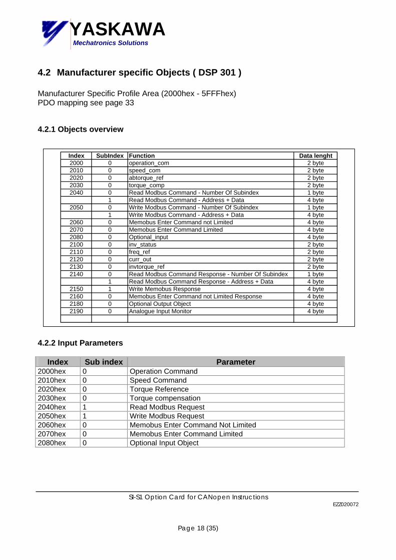
4.2 Manufacturer specific Objects ( DSP 301 ) Manufacturer Specific Profile Area (2000hex - 5FFFhex) PDO mapping see page 33
4.2.1 Objects overview
Index SubIndex Function Data lenght2000 0 operation_com 2 byte2010 0 speed_com 2 byte2020 0 abtorque_ref 2 byte2030 0 torque_comp 2 byte2040 0 Read Modbus Command - Number Of Subindex 1 byte
1 Read Modbus Command - Address + Data 4 byte2050 0 Write Modbus Command - Number Of Subindex 1 byte
1 Write Modbus Command - Address + Data 4 byte2060 0 Memobus Enter Command not Limited 4 byte2070 0 Memobus Enter Command Limited 4 byte2080 0 Optional_input 4 byte2100 0 inv_status 2 byte2110 0 freq_ref 2 byte2120 0 curr_out 2 byte2130 0 invtorque_ref 2 byte2140 0 Read Modbus Command Response - Number Of Subindex 1 byte
1 Read Modbus Command Response - Address + Data 4 byte2150 1 Write Memobus Response 4 byte2160 0 Memobus Enter Command not Limited Response 4 byte2180 0 Optional Output Object 4 byte2190 0 Analogue Input Monitor 4 byte
4.2.2 Input Parameters
Index Sub index Parameter 2000hex 0 Operation Command 2010hex 0 Speed Command 2020hex 0 Torque Reference 2030hex 0 Torque compensation 2040hex 1 Read Modbus Request 2050hex 1 Write Modbus Request 2060hex 0 Memobus Enter Command Not Limited 2070hex 0 Memobus Enter Command Limited 2080hex 0 Optional Input Object

YASKAWAMechatronics Solutions
SI-S1 Option Card for CANopen Instructions EZZ020072
Page 19 (35)
4.2.1.1 Input data to inverter
Input data Function Operation Command See the table Speed command unit depends on parameter O1-03 ( n35 ) [RPM/Hz/%] Torque Reference / Limit 0.1% (Vector control mode only) Torque compensation 0.1% (Vector control mode only) High speed input data to inverter, updated every 5 ms. The speed command is taken directly with the same factor. There is no automatic switching of the factor depending of the value of the speed reference The reference is always input with two decimal places. 4.2.1.2 Operation Command
Bit No
Description Parameters E7, F7, G7 Parameters V7
0 Forward Run Effective when the setting is B1-02=3 Effective when the setting is n03=3 1 Reverse Run Effective when the setting is B1-02=3 Effective when the setting is n03=3 2 Terminal 3
function Depends on H1-01 setting Depends on n53 setting
3 Terminal 4 function
Depends on H1-02 setting Depends on n54 setting
4 Terminal 5 function
Depends on H1-03 setting Depends on n55 setting
5 Terminal 6 function
Depends on H1-04 setting Depends on n56 setting
6 Terminal 7 function
Depends on H1-05 setting not used
7 Terminal 8 function
not used not used
8 External Fault (EF0)
9 Fault Reset A Not used B Not used C Not used D Not used E Not used F Not used

YASKAWAMechatronics Solutions
SI-S1 Option Card for CANopen Instructions EZZ020072
Page 20 (35)
4.2.1.3 Optional Input Object
Index Subindex Name Data
2080 0 Optional Input Object application dependent
4.2.3 Output Parameters
Index Sub index Parameter 2100hex 0 Inverter Status 2110hex 0 Output Frequency 2120hex 0 Output current 2130hex 0 Output Torque 2140hex 1 Read Memobus Response 2150hex 1 Write Memobus Response 2160hex 0 Memobus Enter Command Not Limited Response 2180hex 0 Optional Output Object 2190hex 0 Analogue Input Monitor 4.2.3.1 Output data from inverter
Output data Function Inverter Status See the table Output Frequency unit depends on parameter O1-03 ( n35 ) [RPM/Hz/%] Output Current 0.1A or 0.01A (depend on inverter capacity) Output Torque 0.1% (Vector control mode only) High speed output data, updated every 5 ms 4.2.3.2 Inverter Status Bit No Description
0 Running 1 Zero Speed 2 Reverse Running 3 Reset Command Receiving 4 Speed Agree 5 Inverter Ready 6 Minor Fault 7 Major Fault 8 OPE error 9 During Momentary Power Ride-through ( not used with V7 ) A Local/Remote B Terminal 9-10 Output ( MA, MB with V7) C Terminal 25 Output ( P1 with V7, M1-M2 with F7 ) D Terminal 26 Output ( P2 with V7, M3-M4 with F7 ) E Motor Selection ( not used with V7 ) F Zero Servo Completion ( used only with pulsgenerator )

YASKAWAMechatronics Solutions
SI-S1 Option Card for CANopen Instructions EZZ020072
Page 21 (35)
4.3.2 Memobus data 4.2.2.1 Memobus Read request
Index Subindex Name Data
2040 0 Number of entries 1 Memobus Read Request Memobus Address 16 bit
4.2.2.2 Memobus Write Request
Index Subindex Name Data
2050 0 Number of entries 1 Memobus Write Request Memobus Address +
Data 16 bit + 16 bit
4.2.2.3 Memobus Enter Command Not Limited ( not needed with a V7 drive )
Index Subindex Name Data
2060 0 Not Limited Enter Command “ SAVE “ To enable inverter parameter changes this enter command must be used. It is enough to use it after the last changed inverter parameter. ( If a block transfer is done please use this enter command only one time after the last parameter changed ) The use of this command is not limited.
Attention :
After power of the inverter all changes are lost !!!! 4.2.2.4 Memobus Enter Command Limited

YASKAWAMechatronics Solutions
SI-S1 Option Card for CANopen Instructions EZZ020072
Page 22 (35)
Index Subindex Name Data
2070 0 Limited Enter Command “ SAVE “
To enable inverter parameter changes this enter command must be used. It is enough to use it after the last changed inverter parameter. ( If a block transfer is done please use this enter command only one time after the last parameter changed ) The use of this command is limited up to 100000 times !!!!
Attention :
After power of the inverter all changes will be kept !!!! 4.2.2.5 Memobus Read Response
Index Subindex Name Data
2140 0 Number of entries 1 Memobus Read Response Memobus Address +
Data 16 bit + 16 bit
4.2.2.6 Memobus Write Response
Index Subindex Name Data
2150 0 Number of entries 1 Memobus Write Response Memobus Address +
Data 16bit + 16 bit
4.2.2.7 Memobus Enter Command Not Limited Response

YASKAWAMechatronics Solutions
SI-S1 Option Card for CANopen Instructions EZZ020072
Page 23 (35)
Index Subindex Name Data
2160 0 Not Limited Enter Response “ SAVE “ 32 bit
4.2.2.8 Optional Output Object
Index Subindex Name Data
2180 0 Optional Output Object 32 bit free for future use
4.2.2.9 Analogue Input Monitor
Index Subindex Name Data
2190 0 Analogue Input Monitor 32 bit Monitors the value of the
Analog input of the inverter

YASKAWAMechatronics Solutions
4.3 Drives and motion control ( DSP 402 )
4.3.1 Common entries Index (hex) 60FD Object Name Digital_input Description Simple digital output of device
YASKAWA specifies this object as the inverter digital output monitor. ( Input of the network )
Class Option Access Read only PDO Mapping Possible Units -- Value range 0 … (232-1)
Corresponding data of E7, F7, G7, V7 E7, F7, G7 V7
Bit No. 16 : ( terminal MA/MB MC ) 17 : ( terminal M1 M2 ) 18 : ( terminal M3 M4 ) 19: 20: 21: 22: 23: bit 0 to 15 are reserved as standard function and no specification for E7, F7, G7
Bit No. 16 : ( terminal MA/MB output ) 17 : ( terminal P1 output ) 18 : ( terminal P2 output ) 19: 20: 21: 22: 23: bit 0 to 15 are reserved as standard function and no specification for V7
SI-S1 Option Card for CANopen Instructions EZZ020072
Page 24 (35)

YASKAWAMechatronics Solutions
SI-S1 Option Card for CANopen Instructions EZZ020072
Page 25 (35)
Index (hex) 60FE Object Name Digital_output Description Simple digital input for devices
YASKAWA specifies this object as additional digital inputs of the inverter ( output of the network )
Class Option Access Read write ( used as write only ) PDO Mapping Possible Units -- Value range 0 … (232-1)
Corresponding data of E7, F7, G7, V7 E7, F7, G7 V7
Bit No. 18 : ( terminal 3 function ) 19 : ( terminal 4 function ) 20 : ( terminal 5 function ) 21 : ( terminal 6 function ) 22 : ( terminal 7 function ) 23 : ( terminal 8 function ) not used with E7, F7,G724 : ( EFO ) 25 : ( Fault reset ) bit 0 to 15 are reserved as standard function and no specification for E7, F7, G7
Bit No. 18 : ( terminal 3 function ) 19 : ( terminal 4 function ) 20 : ( terminal 5 function ) 21 : ( terminal 6 function ) 22 : ( terminal 7 function ) 23 : not used 24 : ( EFO ) 25 : ( Fault reset ) bit 0 to 15 are reserved as standard function and no specification for V7

YASKAWAMechatronics Solutions
SI-S1 Option Card for CANopen Instructions EZZ020072
Page 26 (35)
4.3.2 Device control Index (hex) 6040 Object Name Controlword Description Set our device to different states
Class Mandatory Access Read write PDO Mapping Possible Units -- Value range 0 … 65535 Index (hex) 6041 Object Name Statusword Description Shows the different states of our device
Class Mandatory Access Read only PDO Mapping Possible Units -- Value range 0 … 65535

YASKAWAMechatronics Solutions
SI-S1 Option Card for CANopen Instructions EZZ020072
Page 27 (35)
Index (hex) 6060 Object Name Modes_of_operation Description Switches to the actual chosen operation mode.
Only G5 with pulsgenerator has torque control mode. The V7 has only one operation mode ( Velocity Mode ).
Class Mandatory Access Write only PDO Mapping Possible Units -- Value range -128…127
Corresponding data of E7, F7, G7, V7 E7, F7, G7 V7
Modes_of_Operation 2 Velocity Mode 4 Torque Profile Mode not implemented!!!
Modes_of_Operation 2 Velocity Mode 4 Torque Profile Mode ..⇒ not possible
Index (hex) 6061 Object Name Modes_of_operation_display Description Shows the mode of our device
Class Mandatory Access Read only PDO Mapping Possible Units -- Value range -128…127
Corresponding data of E7, F7, G7, V7 E7, F7, G7 V7
2 Velocity Mode 5 Torque Profile Mode not implemented 6
..⇒ always : 2 Velocity Mode

YASKAWAMechatronics Solutions
SI-S1 Option Card for CANopen Instructions EZZ020072
Page 28 (35)
4.3.3 Velocity Mode Index (hex) 6042 Object Name vl_target_velocity Description vl_target_velocity is the required speed of the system.
It is interpreted in rpm . Parameter o1-03 has to be set by customer before operation.!! Vl_target_velocity has to be multiplicated with the Dimension factor. The Dimension factor can be used for setting the resolution also .
Class Mandatory Access Read write PDO Mapping Possible Units Rpm Value range -32768…0…32767 Index (hex) 6043 Object Name vl_velocity_demand Description vl_target_velocity is the speed reference provided by the ramp function
and limiting functions in units of rpm
Class Mandatory Access Read only PDO Mapping Possible Units Rpm Value range -32768…0…32767

YASKAWAMechatronics Solutions
SI-S1 Option Card for CANopen Instructions EZZ020072
Page 29 (35)
Index (hex) 6044 Object Name vl_control_effort Description vl_control_effort is the output frequency of our inverter to the motor.
The unit is rpm In case of close loop vector control mode the exact motor speed can be read out.
Class Mandatory Access Read only PDO Mapping Possible Units Rpm Value range -32768…0…32767 Index (hex) 6046 Object Name vl_velocity_min_max_amount Description vl_velocity_min_max_amount consists of two subindex.
One for max and one for the min amount. They do not have units. Yaskawa does interpret these values as rpm
Class Mandatory Access Read write PDO Mapping Possible Units Rpm Value range 0..( 2 32-1 )

YASKAWAMechatronics Solutions
SI-S1 Option Card for CANopen Instructions EZZ020072
Page 30 (35)
Index (hex) 6048 Object Name vl_velocity_acceleration Description Vl_velocity_acceleration specifies the acceleration time
It consists of two subindex ( delta_speed and delta_time). So it is generated as the quotient of the delta_speed and delta_time subindex. This object correspond to the acceleration time of the inverter.
Class Mandatory Access Read write PDO Mapping Possible Units Rpm ( subindex 1 ); Second ( subindex 2 ) Value range 0…(2 23 –1 ) ( subindex 1 ); 0…65535 ( subindex 2 ) Index (hex) 6049 Object Name vl_velocity_deceleration Description Vl_velocity_deceleration specifies the deceleration time
It consists of two subindex ( delta_speed and delta_time). So it is generated as the quotient of the delta_speed and delta_time subindex. This object correspond to the acceleration time of the inverter.
Class Mandatory Access Read write PDO Mapping Possible Units Rpm ( subindex 1 ); Second ( subindex 2 ) Value range 0…(2 23 –1 ) ( subindex 1 ); 0…65535 ( subindex 2 )

YASKAWAMechatronics Solutions
SI-S1 Option Card for CANopen Instructions EZZ020072
Page 31 (35)
Index (hex) 604A Object Name vl_velocity_quick_stop Description Vl_velocity_quick_stop specifies the quick stop ramp.
It consists of two subindex ( delta_speed and delta_time) So it is generated as the quotient of the delta_speed and delta_time subindex. This object correspond to the emergency stop time of the inverter.
Class Optional Access Read write PDO Mapping Possible Units rpm ( subindex 1 ); Second ( subindex 2 ) Value range 0…(2 23 –1 ) ( subindex 1 ); 0…65535 ( subindex 2 ) Index (hex) 604C Object Name vl_dimension_factor Description Vl_dimension_factor is to multiplicate the Target Velocity ( reference speed )
with a customer specific factor. It consists of two subindex ( numerator and denominator ) So it is generated as the quotient numerator and denominator
Class Optional Access Read write PDO Mapping Possible Units Rpm ( subindex 1 ); Second ( subindex 2 ) Value range 0…(2 23 –1 ) ( subindex 1 ); 0…65535 ( subindex 2 )

YASKAWAMechatronics Solutions
SI-S1 Option Card for CANopen Instructions EZZ020072
Page 32 (35)
Index (hex) 604D Object Name vl_pole_number Description Vl_pole_number sets the number of poles of the connected motor
This data in necessary for us to calculate for rpm ( all velocity values ) to Hz. It is mandatory for the customer to set the pole number.!!!! This is possible enter by digital operator or by object dictionary entry.
Class Optional Access Read write PDO Mapping Possible Units - ( number of poles ) Value range 0…255

YASKAWAMechatronics Solutions
SI-S1 Option Card for CANopen Instructions EZZ020072
Page 33 (35)
5 PDO Mapping
5.1 Receive PDO
Receive PDO Parameter Receive PDO Mapping PDO
number COB-ID Index Mapped objects Index
1 201hex 1400 Subindex 1: 6040 1600 2 301hex 1401 Subindex 1: 6040
Subindex 2 : 6060 1601
6 241hex 1405 Subindex 1: 6040 Subindex 2 : 6042
1605
7 341hex 1406 Subindex 1: 6040 Subindex 2 : 60FE
1606
8 381hex 1407 Subindex 1: 6040 Subindex 2 : 6060
1607
21 Not
assigned 1414 Subindex1 : 6048 sub1
Subindex2 : 6048 sub21614
22 Not assigned
1415 Subindex1 : 6049 sub1Subindex2 : 6049 sub2
1615
23 Not assigned
1416 Subindex1 : 604A sub1Subindex2 : 604A sub2
1616
24 Not assigned
1417 Subindex1 : 604C sub1Subindex2 : 604C sub2
1617
36 Not
assigned 1423 Subindex1 : 2000 1623
37 Not assigned
1424 Subindex1 : 2010 1624
38 Not assigned
1425 Subindex1 : 2020 1625
39 Not assigned
1426 Subindex1 : 2030 1626
40 Not assigned
1427 Subindex1 : 2040 sub1
1627
41 Not assigned
1428 Subindex1 : 2050 sub1 1628

YASKAWAMechatronics Solutions
SI-S1 Option Card for CANopen Instructions EZZ020072
Page 34 (35)
5.2 Transmit PDO
Transmit PDO Parameter Transmit PDO Mapping PDO
number COB-ID Index Mapped objects Index
1 181hex 1800 Subindex 1: 6041 1A00 2 281hex 1801 Subindex 1: 6041
Subindex 2 : 6061 1A01
6 1C1hex 1805 Subindex 1: 6041 Subindex 2 : 6044
1A05
7 2C1hex 1806 Subindex 1: 6041 Subindex 2 : 60FD
1A06
21 Not
assigned 1814 Subindex1 : 6042 1A14
22 Not assigned
1815 Subindex1 : 6043 1A15
23 Not assigned
1816 Subindex1 : 6048 sub1Subindex2 : 6048 sub2
1A16
24 Not assigned
1817 Subindex1 : 6049 sub1Subindex2 : 6049 sub2
1A17
25 Not assigned
1818 Subindex1 : 604A sub1Subindex2 : 604A sub2
1A18
26 Not assigned
1819 Subindex1 : 604C sub1Subindex2 : 604C sub2
1A19
36 Not
assigned 1823 Subindex1 : 2100 1A23
37 Not assigned
1824 Subindex1 : 2110 1A24
38 Not assigned
1825 Subindex1 : 2120 1A25
39 Not assigned
1826 Subindex1 : 2130 1A26
40 Not assigned
1827 Subindex1 : 2140 sub1
1A27
41 Not assigned
1828 Subindex1 : 2160 1A28

YASKAWAMechatronics Solutions
SI-S1 Option Card for CANopen Instructions EZZ020072
Page 35 (35)
6 Related E7,F7;G7 Parameters
EF0; External Fault Signal from Serial Communication Option Card (SI-S1). Operation command Bit.8.
BUS; Serial Communication Error between Serial Communication Option Card (SI-S1)
and CANopen network.
7 V7 Related Parameter
Parameter No.
Name Description FactorySetting
b1-01 Frequency Reference Selection
0: Digital Operator 1: Terminal 2: Serial Communication 3: Option 3 = The Frequency Reference comes from SI-S1 option card.
1
b1-02 Operation Method Selection 0: Digital Operator 1: Terminal 2: Serial Communication 3: Option 3 = The Run Command comes from SI-S1 option card.
1
F6-01 Stopping Method after communication error
0: Ramp to stop according to C1-02 setting 1: Coast to stop 2: Ramp to stop according to C1-09 setting (fast-stop) 3; Operation continues, alarm only
1
F6-02 Input level of external error form option card
0: Always detected 1: Detected only during running
0
F6-03 Stopping method for external error from option card
0: Rump to stop according to C1-02 setting 1: Coast to stop 2: Ramp to stop according to C1-09 setting (fast-stop) 3; Operation continues, alarm only
1
Parameter No.
Name Description FactorySetting
n03 Operation reference selection
3: Option 3 = The run command comes from SI-S1 option card.
0
n04 Frequency reference selection
9: Option 9 = The frequency reference comes from SI-S1 option card.
1