Embed Size (px)
Citation preview

YASKAWA
DriveWizardOnline Manual
YASKAWA
YASKAWA ELECTRIC CORPORATION
MANUAL NO. TOEP C730600 17AApril 2006 06-4C
05-7

ii
Safety-Related SymbolsThe following symbols are used in this manual according to the safety-related content.Be sure to observe text annotated with these safety symbols as their content is important.
Furthermore, items marked with may have important consequences depending on the situation.Warning-related symbols differ between ISO and JIS standards.
This manual uses ISO standard symbols.Product warning labels may use either the ISO or JIS standards. Treat either in the same manner.
Indicates precautions that, if not heeded, could possibly result in loss of life or serious injury.
Indicates precautions that, if not heeded, could result in relatively seri-ous or minor injury, damage to the product, or faulty operation.
ISO Standards JIS Standards
! WARNING
! CAUTION
! CAUTION
! !
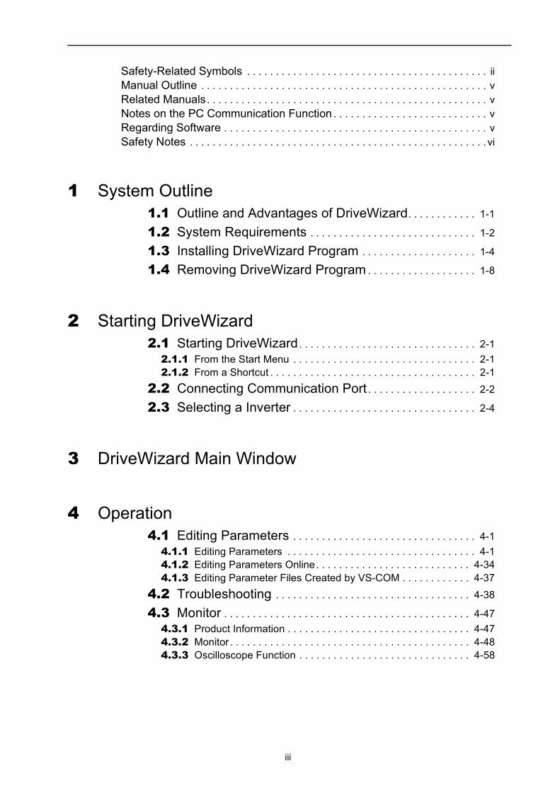
Safety-Related Symbols . . . . . . . . . . . . . . . . . . . . . . . . . . . . . . . . . . . . . . . . . . iiManual Outline . . . . . . . . . . . . . . . . . . . . . . . . . . . . . . . . . . . . . . . . . . . . . . . . . . vRelated Manuals. . . . . . . . . . . . . . . . . . . . . . . . . . . . . . . . . . . . . . . . . . . . . . . . . vNotes on the PC Communication Function . . . . . . . . . . . . . . . . . . . . . . . . . . . vRegarding Software . . . . . . . . . . . . . . . . . . . . . . . . . . . . . . . . . . . . . . . . . . . . . . vSafety Notes . . . . . . . . . . . . . . . . . . . . . . . . . . . . . . . . . . . . . . . . . . . . . . . . . . . . vi
1 System Outline1.1 Outline and Advantages of DriveWizard. . . . . . . . . . . . 1-1
1.2 System Requirements . . . . . . . . . . . . . . . . . . . . . . . . . . . . . 1-2
1.3 Installing DriveWizard Program . . . . . . . . . . . . . . . . . . . . 1-4
1.4 Removing DriveWizard Program . . . . . . . . . . . . . . . . . . . 1-8
2 Starting DriveWizard2.1 Starting DriveWizard. . . . . . . . . . . . . . . . . . . . . . . . . . . . . . . 2-12.1.1 From the Start Menu . . . . . . . . . . . . . . . . . . . . . . . . . . . . . . . . 2-12.1.2 From a Shortcut . . . . . . . . . . . . . . . . . . . . . . . . . . . . . . . . . . . . 2-1
2.2 Connecting Communication Port . . . . . . . . . . . . . . . . . . . 2-2
2.3 Selecting a Inverter . . . . . . . . . . . . . . . . . . . . . . . . . . . . . . . . 2-4
3 DriveWizard Main Window
4 Operation4.1 Editing Parameters . . . . . . . . . . . . . . . . . . . . . . . . . . . . . . . . 4-14.1.1 Editing Parameters . . . . . . . . . . . . . . . . . . . . . . . . . . . . . . . . . 4-14.1.2 Editing Parameters Online. . . . . . . . . . . . . . . . . . . . . . . . . . . 4-344.1.3 Editing Parameter Files Created by VS-COM . . . . . . . . . . . . 4-37
4.2 Troubleshooting . . . . . . . . . . . . . . . . . . . . . . . . . . . . . . . . . . 4-38
4.3 Monitor . . . . . . . . . . . . . . . . . . . . . . . . . . . . . . . . . . . . . . . . . . . 4-474.3.1 Product Information . . . . . . . . . . . . . . . . . . . . . . . . . . . . . . . . 4-474.3.2 Monitor . . . . . . . . . . . . . . . . . . . . . . . . . . . . . . . . . . . . . . . . . . 4-484.3.3 Oscilloscope Function . . . . . . . . . . . . . . . . . . . . . . . . . . . . . . 4-58
iii

4.4 Motor Parameter Autotuning . . . . . . . . . . . . . . . . . . . . . . 4-79
4.5 Test Run . . . . . . . . . . . . . . . . . . . . . . . . . . . . . . . . . . . . . . . . . 4-914.5.1 Manual Operation . . . . . . . . . . . . . . . . . . . . . . . . . . . . . . . . . 4-914.5.2 Pattern Operation . . . . . . . . . . . . . . . . . . . . . . . . . . . . . . . . . 4-95
5 Technical Support
Revision History
iv

Manual OutlineThis manual explains the following areas for DriveWizard users.• Outline of DriveWizard Functions and Operation• DriveWizard Installation/Removal
Related ManualsBe sure to refer to the corresponding technical materials regarding related Inverters, options, and other equipment.Use this product only with a full understanding of its specifications, service life, and other important information.
Notes on the PC Communication Function
Regarding Software
Usage Notes• Use this software on one specified PC. Request a separate license to use this software on
another computer.• Copying of this software for purposes other than use as backup copies is strictly prohib-
ited.• Carefully store the CD-ROM (original medium) upon which this software is written.• Reverse compiling or assembly of this software is strictly prohibited.• Use of this software in whole or in part by a third party through transfer, exchange, resale,
and so forth, is strictly prohibited without the prior agreement of Yaskawa Electric Corpo-ration.
• Copyright and all other rights for this software are reserved by Yaskawa Electric Corpora-tion.
• Do not change the Inverter parameters or the MEMOBUS data using other methods, such as communication connection terminals or communication cards, while using DriveWizard.
If the Inverter parameters or the MEMOBUS data are changed using other methods while using DriveWizard, the data of DriveWizard may disagree with the Inverter data and result in a malfunc-tion.
! CAUTION
v

Operating Systems and Registered Trademarks• Windows 98, Windows NT, Windows 2000, Windows Me, and Windows XP are regis-
tered trademarks of Microsoft Corporation in the United States.• Adobe, the Adobe logo, and Reader are either registered trademarks or trademarks of
Adobe Systems Incorporated in the United States and /or other countries.
Safety NotesThe following are important cautionary items that must be observed in the wiring and use of this product.
Notes on Wiring
Usage Notes
• Never change cables while DriveWizard is running. Always quit DriveWizard before changing connections.
The operation of both or either the PC or Inverter cannot be assured if this is not observed.
• Always be sure to quit DriveWizard before turning the Inverter power off or on.
The operation of both or either the PC or Inverter cannot be assured if this is not observed.
• Always be sure to stop the Inverter before connecting the Inverter to a PC that has DriveWizard installed.
The operation of the Inverter cannot be assured if this is not observed.
! CAUTION
! CAUTION
vi

1.1 Outline and Advantages of DriveWizard
1 System OutlineThis section includes an outline of the DriveWizard system, and explains its advantages and preparation prior to use.
1.1 Outline and Advantages of DriveWizardDriveWizard is an engineering tool for setup, test run, and maintenance of Yaskawa Inverters.This product provides uniform features and functions enabling everyone from beginners to persons experienced in Inverter tuning to easily perform connections, test runs, and maintenance right out of the box.Main Functions• Parameter editing and help displays appropriate for each parameter• Display of Inverter data, such as I/O signals and the internal status, and product data• Troubleshooting (help displays appropriate to the cause and corrective action)• Test run (Manual operation, pattern operation)• Motor parameter autotuning function• Oscilloscope functionNote: Some DriveWizard functions may be unusable depending on the Inverter type. Unusable functions will
appear dimmed on the selection menu.
1-1

1.2 System Requirements
1.2 System RequirementsDriveWizard requires the following minimum system configuration.
Personal Computer (PC) PC/AT DOS/V-compatible device* Operation cannot be assured on the NEC PC9821 series.
Processor Pentium 200MHz
Main Memory 64MB (96MB recommended)
Free Hard Disk Space At Normal Setup• 100MB (200MB recommended at installation)
Monitor Super VGA (800×600 or greater using a small font)
Number of Colors 256 colors (65536 colors recommended)
Operating System (OS) • Windows 98• Windows NT4.0 Service Pack 3 or later (IE4.01 Service Pack 2 or later)• Windows 2000• Windows Me• Windows XP
Communication RS-232C, RS-422, and RS-485 communicationsUse an USB serial conversion adapter for communications with an USB port. Use an available standard adapter at all electric or computer stores.
Example• Manufacture: I-O Data Device, INC.• Model: USB-RSAQ3• Specifications: USB I/F Spec.1.1compatible
Max. DTE speed: 230.4kbpsUSB: B receptacle RS-232C: D-sub9 pin (female)Power supply voltage: 5 VDC (from bus)
Some serial conversion adapters cannot be used for communications because of their compatibility with the PC or other factors.
Communication Cables for Inverter to PC Connection
For a RS-232C communication cable, contact Yaskawa if necessary.
• When using RS-422 or RS-485 communications, refer to each Inverter’s instruction manuals to prepare a communication cable and perform wiring.
• If using a VS mini J7 Inverter, a SI-232/J7 Remote Interface Unit is required.
Other One node or more RS-232C, RS-422, or RS-485 I/FCD-ROM drive (for installation only)Adobe Acrobat Reader (by Adobe Corporation)* Needed when displaying help.
Inverter type Cable Model
Ordering from Yaskawa in Japan
G5 Socket-connector typeW5250
G7, F7, L7, V7, J7, and others
Modular-connector typeWV103
Ordering from Yaskawa outside Japan
G5 Socket-connector typeUWR100-1UWR103-1 (Also used as a cable for writing data in the flash memory)
G7, F7, L7, V7, J7, and others
Modular-connector typeUWR00468-2UWR00468-1 (Also used as a cable for writing data in the flash memory)
1-2

1.2 System Requirements
1. For computers with Windows XP, 2000, and NT, only users with administrator privilege can log on and use DriveWizard. Also, only the user who installed DriveWizard can remove it.
2. For use with Windows XP, pay attention to the following items.• If using NTFS, contact a user with administrator privileges to log on to the
DriveWizard. DriveWizard does not support Limited User Mode on NTFS file systems.
• Multiple users cannot use Drive Wizard at the same time. DriveWizard can only be used by one user at a time.
IMPORTANT
1-3

1.3 Installing DriveWizard Program
1.3 Installing DriveWizard ProgramTo install DriveWizard, run the setup file for DriveWizard. And the installation process will begin. In this process, DriveWizard and the related files will be installed, or stored on the hard disk.Operating conflicts may arise with the other programs during installation. Be sure to quit all other programs before installing DriveWizard.Note: If installing DriveWizard on a computer with Windows XP, 2000, or NT, first log on to the computer as a
user with administrator privileges and then install DriveWizard.
Install the program using the following procedure.1. Insert the CD-ROM into the CD-ROM drive (the D-drive for example).2. If "Autoplay" is enabled, the installation program will automatically start when the CD-
ROM is inserted.
If "Autoplay" is not enabled, either of the following methods may be used.• On the Start menu, select Run. Type "D:\SETUP", and then click OK.• Open the Explorer, load the CD-ROM contents, and double click "D:\SETUP.EXE".
A message will appear, welcoming you to the DriveWizard program.
1-4

1.3 Installing DriveWizard Program
3. Click Next to continue.
4. Select the language to install, and click Next to continue.
5. Choose a destination folder to copy the DriveWizard file to, and click Next to continue.
1-5
1.3 Installing DriveWizard Program
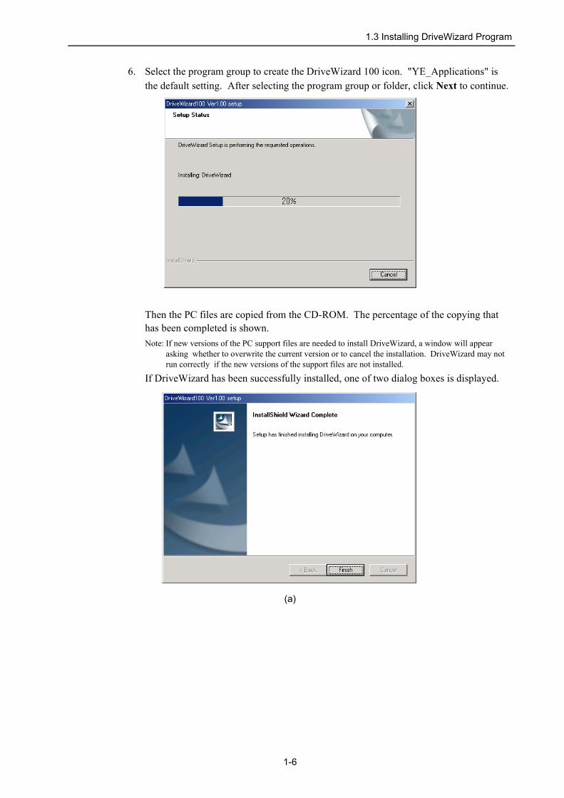
6. Select the program group to create the DriveWizard 100 icon. "YE_Applications" is the default setting. After selecting the program group or folder, click Next to continue.
Then the PC files are copied from the CD-ROM. The percentage of the copying that has been completed is shown.Note: If new versions of the PC support files are needed to install DriveWizard, a window will appear
asking whether to overwrite the current version or to cancel the installation. DriveWizard may not run correctly if the new versions of the support files are not installed.
If DriveWizard has been successfully installed, one of two dialog boxes is displayed.
(a)
1-6
1.3 Installing DriveWizard Program
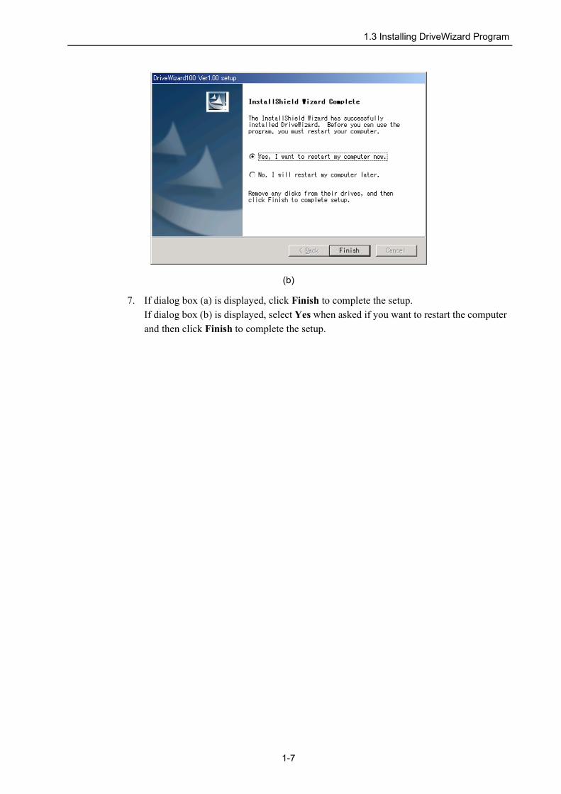
(b)
7. If dialog box (a) is displayed, click Finish to complete the setup.If dialog box (b) is displayed, select Yes when asked if you want to restart the computer and then click Finish to complete the setup.
1-7

1.4 Removing DriveWizard Program
1.4 Removing DriveWizard ProgramNote: If uninstalling DriveWizard from a computer with Windows XP, 2000, or NT, first log on to the computer
as a user with administrator privileges and then uninstall DriveWizard.
Remove the DriveWizard program using the following procedure.1. Click the Start button, point to Settings and click Control Panel.2. Click the Change or Remove Programs icon. The Add/Remove Programs Properties
box appears.
Note: The window layout differs depending on the OS.
1-8

1.4 Removing DriveWizard Program
3. Click the Change or Remove Programs tab if it is not already selected. Click YASKAWA DriveWizard 100 as the program to be removed, and then click Change/Remove.
A confirmation message will appear asking if you are sure you want to remove the program.
4. Click OK to start removing the program. When the program has been successfully removed, the following window will appear telling you that maintenance is complete.
5. Click Finish to complete the removal process.
1-9

2.1 Starting DriveWizard
2 Starting DriveWizardStart DriveWizard using the following method.
2.1 Starting DriveWizardStart DriveWizard:• from the Start menu• from a shortcut
2.1.1 From the Start MenuTo start DriveWizard from the Start menu:1. Click the Start button, and point to Programs.2. Open the YE_Applications folder.3. Click DriveWizard.
2.1.2 From a ShortcutTo start DriveWizard from a shortcut on the desktop:1. Open the YE_Applications folder on the desktop.2. Click DriveWizard.
DriveWizard Startup Screen
2-1

2.2 Connecting Communication Port
2.2 Connecting Communication Port When DriveWizard is initially started, the following screen appears.
Communication Settings Window at Initial Startup
Enter the settings for communications between DriveWizard and the Inverter by means of a serial port.
1. Select the method to set up the Inverter: online or offline.
Online: Select if editing parameters or performing a test run with the Inverter connected
Off-line:Select if editing parameters without the Inverter connected.
The window is divided into five panes, one for each type of monitor. Individual panes can be closed. The panes that are open when you quit DriveWizard will still be open the next time Drive- Wizard is started.
2-2
2.2 Connecting Communication Port
2. If Online is selected, enter the necessary settings to setup communication and protocol.
<Communication Setup>
Port (Items to be displayed differ depending on the type of PC.)Select the communications (COM) port. In the Port list, you can see a list of all the ports that your PC has.
Mode (Single, Range)Select the specifying method of communication address. If you know the communication address, select “Single.” If you do not know the communication address, select “Range.”
Address/Final Address (1 to 32 ports)If “Single” is selected in the Mode selection, enter the communication address which is set in the Invereter constants. If “Range” is selected in the Mode selection, enter the final address in the searching range.
<Protocol Setup>Select the same values as those set in the Inverter parameters. Refer to Inverters instruction manuals because applicable values differ depending on the Inverter type.
Transfer rateSelect from 1200, 2400, 4800, 9600, or 19200 bps.
Parity selectionSelect odd, even, or none
Data lengthSelect 7 or 8 bits.
Stop bitSelect 1 or 2 bits.
3. When all the settings have been made, click OK.
After the Inverters have been successfully connected to DriveWizard, a list of the connected Inverters will appear on the screen.
2-3

2.3 Selecting a Inverter
2.3 Selecting a Inverter When DriveWizard is started, the Inverters that are connected will be scanned through the serial ports. The results of this scan will be displayed in the Inverter Selection box.
Inverter Selection Box
Note: When RS-232C is used, only one Inverter will be displayed.
Use the following procedure to select the Inverter to be connected.Select the Inverter to be connected and then click OK.Click Cancel to close the dialog box and the system will enter offline mode.
<If the Inverter Selection Box is not Displayed>If no Inverter is found, the following message will appear, and the system will enter offline mode.
If the aforementioned message is displayed regardless of whether a Inverter is connected or not, problems may occur in communications.
<If a Connect Confirmation Message is Displayed>If the versions of the Inverter software and DriveWizard are not compatilbe because an earlier version of DriveWizard is used, the following message will appear.
Use a version that is compatible with the version of the Inverter software. If the additional parameters along with software upgrades are not to be used, however, the existing version of DriveWizard can be used.
2-4
2.3 Selecting a Inverter
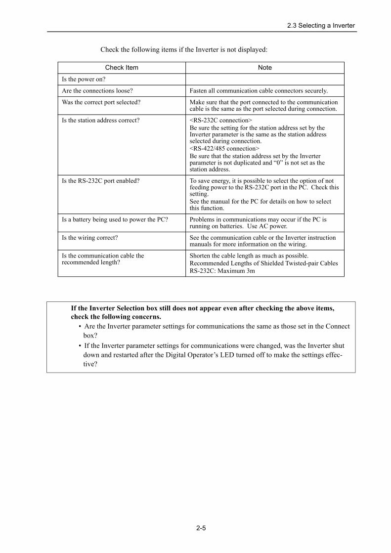
Check the following items if the Inverter is not displayed:
Check Item Note
Is the power on?
Are the connections loose? Fasten all communication cable connectors securely.
Was the correct port selected? Make sure that the port connected to the communication cable is the same as the port selected during connection.
Is the station address correct? <RS-232C connection>Be sure the setting for the station address set by the Inverter parameter is the same as the station address selected during connection.<RS-422/485 connection>Be sure that the station address set by the Inverter parameter is not duplicated and “0” is not set as the station address.
Is the RS-232C port enabled? To save energy, it is possible to select the option of not feeding power to the RS-232C port in the PC. Check this setting.See the manual for the PC for details on how to select this function.
Is a battery being used to power the PC? Problems in communications may occur if the PC is running on batteries. Use AC power.
Is the wiring correct? See the communication cable or the Inverter instruction manuals for more information on the wiring.
Is the communication cable the recommended length?
Shorten the cable length as much as possible.Recommended Lengths of Shielded Twisted-pair CablesRS-232C: Maximum 3m
If the Inverter Selection box still does not appear even after checking the above items, check the following concerns.
• Are the Inverter parameter settings for communications the same as those set in the Connect box?
• If the Inverter parameter settings for communications were changed, was the Inverter shut down and restarted after the Digital Operator’s LED turned off to make the settings effec-tive?
2-5

3 DriveWizard Main WindowThe DriveWizard main window has a menu bar and a toolbar as shown in the following figure.
DriveWizard Main Window
All application functions can be accessed from the menu bar or the toolbar.
3-1

Menu Bar and Menus
DriveWizard Menu Bar
File menu
Help menu
There are also function menus. For details, see Chapter 4.
Reconnect: Switches between Online and Offline modes or between the connected Inverters.
Disconnect: Switches to Offline mode.
Print Setting: Select your preferences for printing the information seen on the screen.See "Print Setting" for details on the setting method.
Exit: Quits DriveWizard.
DriveWizard Help: Displays a help window for DriveWizard.
Inverter Help: Displays a help window for the Inverter.
Introduction Tour: Introduces main functions of DriveWizard
Technical Support: Lists local contacts.
About DriveWizard: Displays version information of DriveWizard.
3-2
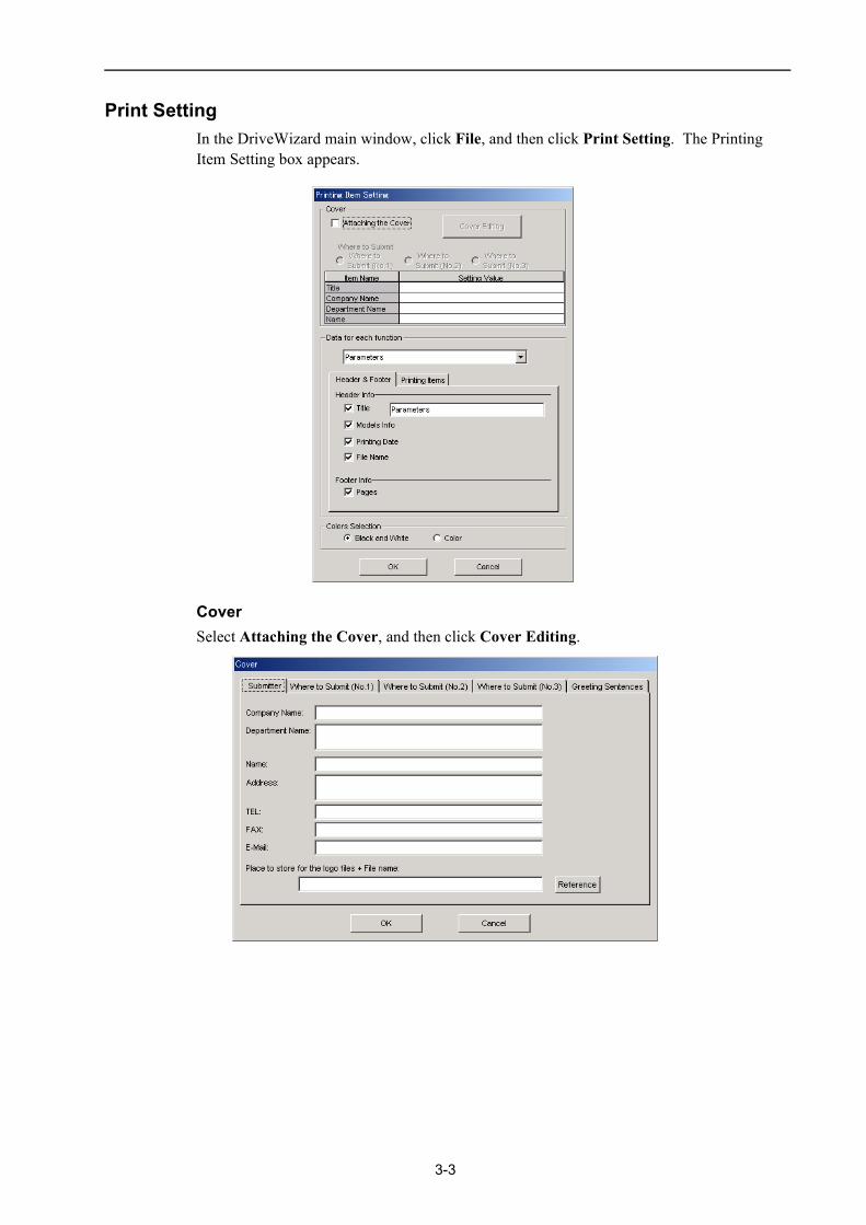
Print SettingIn the DriveWizard main window, click File, and then click Print Setting. The Printing Item Setting box appears.
CoverSelect Attaching the Cover, and then click Cover Editing.
3-3

The Cover box appears, displaying the Submitter tab in front. Use the formatting options on the tabs to control the content of the cover, such as the greeting sentences and where to submit the information. After the setting is finished, click OK.
Data for each functionDepending on which one of the functions you select, the items that you can print will differ.
3-4
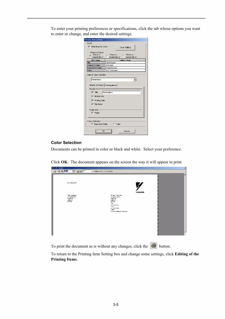
To enter your printing preferences or specifications, click the tab whose options you want to enter or change, and enter the desired settings.
Color SelectionDocuments can be printed in color or black and white. Select your preference.
Click OK. The document appears on the screen the way it will appear in print.
To print the document as is without any changes, click the button.
To return to the Printing Item Setting box and change some settings, click Editing of the Printing Items.
3-5

ToolbarClick an icon on the toolbar to directly select its corresponding function.
DriveWizard Toolbar
ToolbarButton
Function Name
Parameter Editing
Parameter Online Editing
Troubleshooting
Product Information
Status Monitor
Motion Monitor
Input Signal Monitor
Output Signal Monitor
All Monitor
Oscilloscope Function
Manual Operation
Pattern Operation
Motor Parameter Autotuning
3-6

4.1.1 Editing Parameters
4 Operation
4.1 Editing ParametersThe following two methods exist for editing parameters.• Using the Parameter Edit window• Using the Parameter Online Edit window
4.1.1 Editing ParametersParameters can be displayed or edited in the Parameter Edit window.The windows differ in the Online and Offline modes.
Parameter Editing when Online In the DriveWizard main window, click Parameters and then click Edit Parameters. The Parameter Edit window for the online mode appears.
Parameter Edit Window (Online Mode)
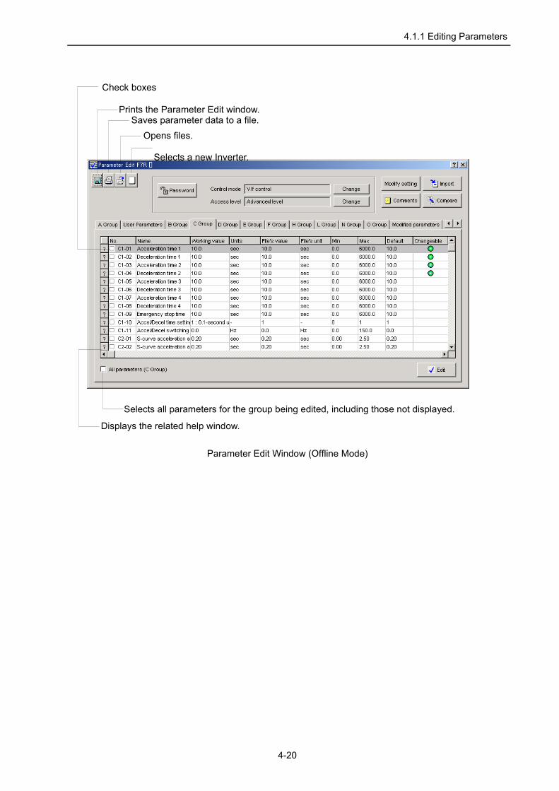
Prints the Parameter Edit window.Saves parameter data to a file.
Displays the related help window.
Selects all parameters for the group being edited, including those not displayed.
Check boxes
4-1

4.1.1 Editing Parameters
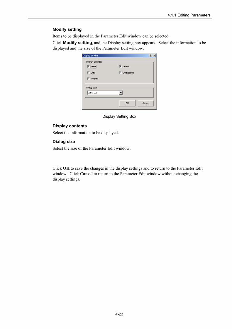
Modify setting Items to be displayed in the Parameter Edit window can be selected.Click Modify setting, and the Display setting box appears. Select the information to be displayed and the size of the Parameter Edit window.
Display Setting Box
Display contentsSelect the information to be displayed.
Dialog sizeSelect the size of the Parameter Edit window.
Click OK to save the changes in the display settings and to return to the Parameter Edit window. Click Cancel to return to the Parameter Edit window without changing the display settings.
4-2

4.1.1 Editing Parameters
Control ModeEdits the parameter for the control mode and related parameters that are changed when the control mode is changed.
Click Change next to the Control mode or double-click Control method selection (G5, F7, G7, L7) or Control mode (V7) in the list in the Parameter Edit window. The following dialog box appears.
Select the control mode in the list box, and related parameters are displayed on the list. Click OK to change the parameter settings and return to the Parameter Edit window. Click Cancel to return to the Parameter Edit window without changing the parameter settings.Note: The control mode can be changed in the edit box opened by clicking Edit.
Access LevelEdits the parameter for the access level.
Click Change next to the Access level or double-click Constant access level (G5, F7, G7, L7) or Constant selection/initialization (V7, J7) in the list in the Parameter Edit window. The following dialog box appears.
Select the access level in the list box or type the value. Click OK to change the access level and return to the Parameter Edit window. Only parameters that can be viewed in the selected access level are displayed. Click Cancel to return to the Parameter Edit window without changing the parameter setting.
4-3

4.1.1 Editing Parameters
EditThe parameter can be viewed and then changed in the Edit box. Select the parameter to be changed, and click Edit or double-click the parameter, and the Edit box appears. The Edit box differs according to the parameter selected.
<Numerical type Edit Box>
Select the value using the spin button or type the value.
<Selection-type Edit Box>
Select the value in the list box or type the value.
4-4

4.1.1 Editing Parameters
<Editing parameters related to other parameters>If the parameter related to other parameters is changed, those parameters are also changed.
Select the parameter to be changed, and click Edit or double-click the parameter, the following dialog box appears.
Select the setting in the list box. Or click Edit and type the value. Then, click OK.
<Setting the user constants to be displayed>The user constants can be selected, which are displayed when the access level is set to the User constant setting.
Select User setting constant (G5, F7, G7, L7) in the list in the Parameter Edit window and click Edit or double-click the parameter, and the User Parameters box appears.Note: This setting is not available in V7 and J7 Inverters.
4-5

4.1.1 Editing Parameters
Select a parameter in the Proposed User Parameter list and click Add. The selected parameter is displayed in the User Parameter list.
After you have finished selecting the user parameters, click OK and the following message appears.
Click OK.
4-6

4.1.1 Editing Parameters
CommentsComments can be typed or edited in the Comment box. Click Comments, and the Comment box appears.
ImportParameter settings can be transferred or imported from a stored file with the Import function. If the imported parameters differ in number from the on-screen parameters (including parameters not currently displayed), the following processing takes place.• If the number of imported parameters is greater
• If the number of imported parameters is fewer
A1-00 : 0000A1-01 : 0000A1-02 : 0001A1-03 : 1100
A1-00 : 0000A1-01 : 0000
Parameters inParameter
Edit window
OverwriteOverwrite
Ignored
ImportedParameters
A1-00 : 0000A1-01 : 0000A1-02 : 0000A1-03 : 0002
A1-00 : 0000A1-01 : 0000
A1-02 : 0000A1-03 : 0002
FactorySettings
Parameters inParameter
Edit windowOverwriteOverwrite
ImportedParameters
4-7

4.1.1 Editing Parameters
1. Click Import, and the Open box appears.
2. Select the file to be transferred, and click Open. The Import parameter box appears.
3. Select the appropriate check boxes for the filter conditions, and click OK .
Displays a list of parameters to be imported.
Opens a list of parameters that are changed when the param-eters for the drive size, control mode, or initialize mode are changed.
4-8

4.1.1 Editing Parameters
Compare to fileThe edited parameter settings can be compared with the values in the specified file for all parameters, including those not displayed, with the Compare function. Check the settings using the following procedure.1. Click Compare at the right-top, and the Open box appears.
2. Select a file and click OK. A message appears and confirms if you want to compare all parameter settings.
Click Cancel to return to the Parameter Edit window without comparing the settings.3. Click OK to start the comparison.
When the comparison has been successfully completed, the following dialog box appears.• If all parameters match
4-9

4.1.1 Editing Parameters
• If not all parameters match
Click the button to save the results of the comparison.
InitializeThe settings of the Inverter can be returned to the factory settings with the Initialize function. Return to the initial settings using the following procedure.1. Click Initialize. Or Select Initialize (G5, F7, G7, L7), Constant selection/initialization
(V7, J7) in the parameter list in the Parameter Edit window. Then click Edit or double-click the parameter. The dialog box in which you can initialize the Inverter settings appears.
Click Cancel to return to the Parameter Edit window without changing the Inverter settings.
2. To set an initialization condition, select a value in the list box. Or, click Edit and type the value.
These items vary according to Inverter type.
4-10

4.1.1 Editing Parameters
3. Usually, the initialization conditions for the inverter capacity, control mode, and Initialize mode do not have to be changed, If changing them, select the new values from each list. Or, Click Edit and type the value.
4. Click OK, and the warning box appears.
5. Click Execute to start initialization.
Compare to InverterThe edited parameter settings can be compared with the values in the Inverter for all parameters, including those not displayed, with the Compare function. Check the settings using the following procedure.1. Click Compare at the bottom. A message appears and comfirms if you want to
compare all parameter settings.
Click Cancel to return to the Parameter Edit window without comparing the settings.2. Click OK to start the comparison, and the percentage of the progress completed is
shown.
When the comparison has been successfully completed, the following dialog box appears.• If all parameters match
4-11

4.1.1 Editing Parameters
• If not all parameters match
Click the button to save the results of the comparison.
Read from InverterSelected parameter settings from the Inverter can be read and then changed by overwriting them with the Read function. Read the parameters using the following procedure.1. Click Read and the dialog box in which you can read the Inverter settings appears.
Displays a list of parameters to be read.
Opens a list of parameters that are changed when the parameters for the drive size, control mode, or initialize mode are changed.
4-12

4.1.1 Editing Parameters
<If parameters are being edited>If parameters are being edited, a message appears and confirms if you want to save the current parameter settings.
• Click OK to save the current parameter settings. The Save As box appears.
• Click No to overwrite the current parameter settings without saving the current parameter settings. The Read from drive box appears.
• Click Cancel to return to the Parameter Edit window without reading the settings.2. Select a reading condition in the list box.
Read selected parametersOnly selected parameters in the Parameter Edit window are read.
Read GroupAll parameters in the displayed group tab are read.
Read all parameterAll parameters, including those not displayed, are read.
3. Select the appropriate check boxes for the filter conditions.4. Click OK to start reading the settings from the Inverter.
4-13

4.1.1 Editing Parameters
<If parameters related to other parameters are included in the selected group>The Read box appears.
Click OK to read the parameter and all related parameters that are listed.
Click Cancel to return to the Parameter Edit window without reading the parameters.
Write to InverterSelected parameter settings can be saved with the Write function. 1. Click Write, and the dialog box in which you can overwrite the Inverter setting
appears.
2. Select an overwriting condition in the list box.• Write selected parameters
Only selected parameters in the Parameter Edit window are overwritten.• Write Group
All parameters in the displayed group tab are overwritten.
Displays a list of parameters to be overwritten.
Opens a list of parameters that are changed when the parameters for the drive size, control mode, or initialize mode are changed.
4-14

4.1.1 Editing Parameters
• Write all parametersAll parameters including those not-displayed are overwritten.
3. Select the appropriate check boxes for the filter conditions.4. Click OK to start saving the settings to the Inverter.
<If parameters related to other parameters are included in the displayed group>The Write box appears.
Click OK to overwrite the parameter and all related parameters that all listed.
Click Cancel to return to the Parameter Edit window without overwriting the parameters.
4-15

4.1.1 Editing Parameters
(Print) Button
The data on the Parameter Edit window can be printed.Only the group parameters selected in the Parameter Edit window can be printed. To print all parameters, select the All parameters check box in the Parameter Edit window, and perform printing.
Click the button, and the Printing Item Setting box appears.
Header Footer Tab Printing Items Tab
CoverSelect Attaching the Cover, and then click Cover Editing. For details, see Chapter 3.
Data for each functionTo enter your printing preferences or specifications, click the tab whose options you want to enter or change, and enter the desired settings.
Color SelectionDocuments can be printed in color or black and white. Select your preference.
4-16

4.1.1 Editing Parameters
After setting is finished, click OK. The document appears on the screen the way it will appear in print.
To print the document as is without any changes, click the button.
To return to the Printing Item Setting box and change some settings, click Editing of the Printing Items.
4-17

4.1.1 Editing Parameters
Parameter Editing when Offline In the DriveWizard main window, click Parameters and then click Edit Parameters. The Parameter Edit box appears.
Select the desired command and click OK.
< When "Open file" is Selected >When “Open file” is selected, the Open box appears.
Select the file to be imported, and click Open.
Open file: Reads in existing parameters.
Open new file: Creates new settings for parameters.
4-18

4.1.1 Editing Parameters
< When "Open new file" is Selected >When “Open new file” is selected, the Drive model selection box appears.
Select the model of Inverter and the area. And type the last four digits of the software number. Click Next to continue, and the Mode selection box appears.Note: Check the software number by checking the nameplate or using the digital operator. Refer to the
Inverter instruction manuals for more information.
Select the value in each list box. Or click each Edit button and type the value. Click Apply and the Parameter Edit window for the offline mode appears.
4-19
4.1.1 Editing Parameters
Parameter Edit Window (Offline Mode)
Prints the Parameter Edit window.Saves parameter data to a file.
Check boxes
Displays the related help window.
Selects all parameters for the group being edited, including those not displayed.
Opens files.
Selects a new Inverter.
4-20

4.1.1 Editing Parameters
(Open) ButtonThe parameters file can be loaded in the Open box. To load the file, use the following procedure.
1. Click the button, and the Open box appears.
2. Select the name of the parameter file to be imported, and click Open.
4-21

4.1.1 Editing Parameters
(New) ButtonA new Inverter can be selected in the Drive model selection box using the New command. To change to a different Inverter, use the following procedure.
Click the button, and the Drive model selection box appears.
Select the model of Inverter and the area. And type the last four digits of the software number. Click Next to continue, and the Mode selection box appears.
Note: Check the software number by checking the nameplate or using the digital operator. Refer to the Inverter instruction manuals for more information.
Select the value in each list box. Or Click each Edit button and type the value. Click Apply and the Parameter Edit wondow for the offline mode appears.
4-22
4.1.1 Editing Parameters
Modify setting Items to be displayed in the Parameter Edit window can be selected.Click Modify setting, and the Display setting box appears. Select the information to be displayed and the size of the Parameter Edit window.
Display Setting Box
Display contentsSelect the information to be displayed.
Dialog sizeSelect the size of the Parameter Edit window.
Click OK to save the changes in the display settings and to return to the Parameter Edit window. Click Cancel to return to the Parameter Edit window without changing the display settings.
4-23

4.1.1 Editing Parameters
Control ModeEdits the parameter for the control mode and related parameters that are changed when the control mode is changed.
Click Change next to the Control mode or double-click Control method selection (G5, F7, G7, L7) or Control mode (V7) in the list in the Parameter Edit window. The following dialog box appears.
Select the control mode in the list box, and related parameters are displayed on the list. Click OK to change the parameter settings and return to the Parameter Edit window. Click Cancel to return to the Parameter Edit window without changing the parameter settings.Note: The control mode can be changed in the edit box opened by clicking Edit.
Access LevelEdits the parameter for the access level.
Click Change next to the Access level or double-click Constant access level (G5, F7, G7, L7) or Constant selection/initialization (V7, J7) in the list in the Parameter Edit window. The following dialog box appears.
Select the access level in the list box or type the value. Click OK to change the access level and return to the Parameter Edit window. Only parameters that can be viewed in the selected access level are displayed. Click Cancel to return to the Parameter Edit window without changing the parameter setting.
4-24

4.1.1 Editing Parameters
EditThe parameter can be viewed and then changed in the Edit box. Select the parameter to be changed, and click Edit or double-click the parameter, and the Edit box appears. The Edit box differs according to the parameter selected.
<Numerical type Edit Box>
Select the value using the spin button or type the value.
<Selection-type Edit Box>
Select the value in the list box or type the value.
4-25

4.1.1 Editing Parameters
<Editing parameters related to other parameters>If the parameter related to other parameters is changed, those parameters are also changed.
Select the parameter to be changed, and click Edit or double-click the parameter, the following dialog box appears.
Select the setting in the list box. Or click Edit and type the value. Then, click OK.
<Setting the user constants to be displayed>The user constants can be selected, which are displayed when the access level is set to the User constant setting.
Select User setting constant (G5, F7, G7, L7) in the list in the Parameter Edit window and click Edit or double-click the parameter, and the User Parameters box appears.Note: This setting is not available in V7 and J7 Inverters.
4-26

4.1.1 Editing Parameters
Select a parameter in the Proposed User Parameter list and click Add. The selected parameter is displayed in the User Parameter list.
After you have finished selecting the user parameters, click OK and the following message appears.
Click OK.
4-27

4.1.1 Editing Parameters
CommentsComments can be typed or edited in the Comment box. Click Comments, and the Comment box appears.
ImportParameter settings can be transferred or imported from a stored file with the Import function. If the imported parameters differ in number from the on-screen parameters (including parameters not currently displayed), the following processing takes place.• If the number of imported parameters is greater
• If the number of imported parameters is fewer
A1-00 : 0000A1-01 : 0000A1-02 : 0001A1-03 : 1100
A1-00 : 0000A1-01 : 0000
Parameters inParameter
Edit window
OverwriteOverwrite
Ignored
ImportedParameters
A1-00 : 0000A1-01 : 0000A1-02 : 0000A1-03 : 0002
A1-00 : 0000A1-01 : 0000
A1-02 : 0000A1-03 : 0002
FactorySettings
Parameters inParameter
Edit windowOverwriteOverwrite
ImportedParameters
4-28

4.1.1 Editing Parameters
1. Click Import, and the Open box appears.
2. Select the file to be transferred, and click Open. The Import parameter box appears.
3. Select the appropriate check boxes for the filter conditions, and click OK .
Displays a list of parameters to be imported.
Opens a list of parameters that are changed when the param-eters for the drive size, control mode, or initialize mode are changed.
4-29

4.1.1 Editing Parameters
Compare to fileThe edited parameter settings can be compared with the values in the specified file for all parameters, including those not displayed, with the Compare function. Check the settings using the following procedure.1. Click Compare at the right-top, and the Open box appears.
2. Select a file and click OK. A message appears and confirms if you want to compare all parameter settings.
Click Cancel to return to the Parameter Edit window without comparing the settings.3. Click OK to start the comparison.
When the comparison has been successfully completed, the following dialog box appears.• If all parameters match
4-30

4.1.1 Editing Parameters
• If not all parameters match
Click the button to save the results of the comparison.
4-31

4.1.1 Editing Parameters
(Print) Button
The data on the Parameter Edit window can be printed.Only the group parameters selected in the Parameter Edit window can be printed. To print all parameters, select the All parameters check box in the Parameter Edit window, and perform printing.
Click the button, and the Printing Item Setting box appears.
Header Footer Tab Printing Items Tab
CoverSelect Attaching the Cover, and the click Cover Editing. For details, see Chapter 3.
Data for each functionTo enter your printing preferences or specifications, click the tab whose options you want to enter or change, and enter the desired settings.
Color SelectionDocuments can be printed in color or black and white. Select your preference.
4-32

4.1.1 Editing Parameters
After setting is finished, click OK. The document appears on the screen the way it will appear in print.
To print the document as is without any changes, click the button.
To return to the Printing Item Setting box and change some settings, click Editing of the Printing Items.
4-33

4.1.2 Editing Parameters Online
4.1.2 Editing Parameters OnlineParameters can be viewed or edited in the Parameter Online Edit window.
Edit parameters online using the following procedure.1. In the DriveWizard main window, click Parameters and then click Edit Online
Parameters. The Parameter Online Edit box appears. The previously saved parameter settings will be displayed.
Parameter Online Edit Box
2. To change the values of the settings, type the new value in the edit box and click Enter. The value will now be displayed in the box on the left.Note: Parameters that cannot be edited appear shaded.
Modified values are also immediately changed in the Inverter. To view different parameters click Set, and the following dialog box appears.
Values edited in the Parameter Online Edit box are also immediately changed in the Inverter.
NOTE
Displays the related help window. Deletes the parameter
displayed at left.
4-34

4.1.2 Editing Parameters Online
3. Click Set to view a parameter other than the "Acceleration time 1." The Parameter selection box appears.
4. Select the parameter to be edited, and click OK. The Parameter Online Edit setting box appears.
5. If there are still parameters to be edited, click Set for a second or third time and set these in the same manner as the first parameter.
Click Delete to delete the currently displayed parameter.
The parameters that appear shaded cannot be edited online or during a run. To hide the pa-rameters, select the check box under the list of parameters.
4-35
4.1.2 Editing Parameters Online
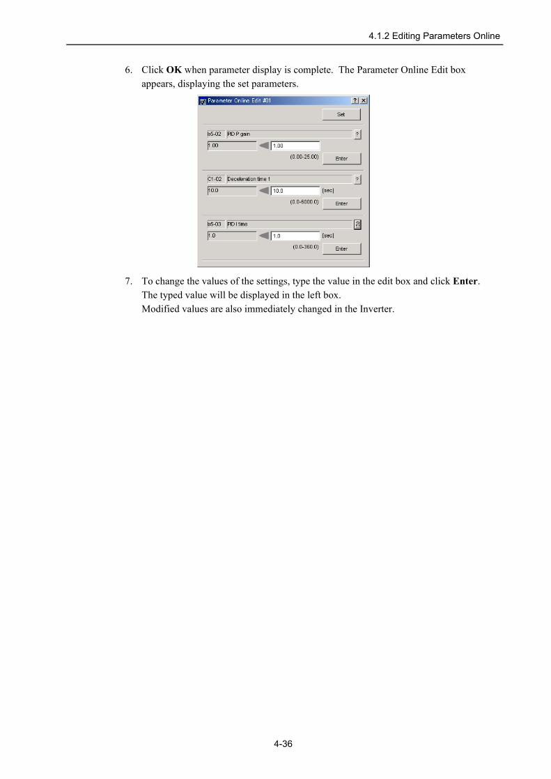
6. Click OK when parameter display is complete. The Parameter Online Edit box appears, displaying the set parameters.
7. To change the values of the settings, type the value in the edit box and click Enter. The typed value will be displayed in the left box.Modified values are also immediately changed in the Inverter.
4-36

4.1.3 Editing Parameter Files Created by VS-COM
4.1.3 Editing Parameter Files Created by VS-COMA parameter file created by VS-COM can be imported with DriveWizard and displayed, edited, and saved as a DriveWizard file.1. Start DriveWizard offline.2. In the DriveWizard main window, clic Parameters, and then click Edit Parameters.
The Parameter Edit box appears.
3. Select “Open file”, and then click OK. The Open box appears.
4. Select “VS-COM Parameter file (*.prm)”, and then click Open. The selected VS-COM parameter file will be imported.
After importing the file, be sure to confirm the parameter settings.IMPORTANT
4-37

4.2 Troubleshooting
4.2 TroubleshootingOnline Troubleshooting
Faults can be viewed in the Trouble Shooting box.In the DriveWizard main window, click Alarm and then click Trouble Shooting. The Trouble Shooting box is displayed.
Trouble Shooting Box (Online)
Note: Display contents differ depending on the Inverter type.
Current Fault
The current fault is displayed.If Inverter status is normal, “No error” is displayed. If Inverter status is faulty, the current fault is displayed. The fault will continue until Inverter status goes normal or another fault occurs.Note: Faults cannot be reset in DriveWizard. End DriveWizard, remove the cause of the fault, and then reset the
fault using the Digital Operator.
Click the button to display details concerning a specific fault and its corrective measures.
Saves the data for faults.
Opens the Drive Type Info box.
4-38

4.2 Troubleshooting
Last Fault
Note: The number of fault history to be stored differs depending on Inverter type. And also, the Elapsed time column is not displayed in some Inverter type.
<Fault History>The Inverter stores a history of the 10 most recent faults. In DriveWizard, these are displayed in the Fault History column in the Trouble Shooting box, and are shown in order of occurrence with their fault code, the details about the type of fault, such as name, and elapsed time at fault.When a new fault occurs, it is displayed as the most recent fault at the top of the list and the previous faults displayed move down on the list with the last fault eliminated.
Click the button, to display details concerning a specific fault and its corrective measures.Click Clear to clear the fault history.
<Fault Trace>The values of monitor items when the fault occurred are displayed. Select a previous fault in the combo box.
Click the button, to display details concerning a specific fault and its corrective measures. Click Clear to clear the fault trace.
Fault trace function is not available for some Inverter type.
4-39

4.2 Troubleshooting
button
To clear the fault history and fault trace, click the button. The following dialog box is displayed.
Click OK to clear the fault history and fault trace. Click Cancel to return to the Trouble Shooting box.Note: Clear the fault history and fault trace after removing the cause of the fault and resetting the fault using the
Digital Operator. If the fault history and fault trace are cleared before resetting the fault, even if the cause of the fault is not removed, the Inverter displays normal status on the Digital Operator. On the other hand, the current fault will continue in DriveWizard.
(Save) button
Click the button, the Save As box is displayed.
Click Save to save the data for current fault, fault history, and fault trace to the specified file.Click Cancel to return to the Trouble Shooting box.
4-40

4.2 Troubleshooting
(Drive Type Info) button
Click the button, the Drive Type Info box is displayed.
Drive Type Info Tab Comment Tab
Comments can be typed in the comment tab.Click OK to save the typed comments.Click Cancel to cancel the typed comments.
4-41
4.2 Troubleshooting
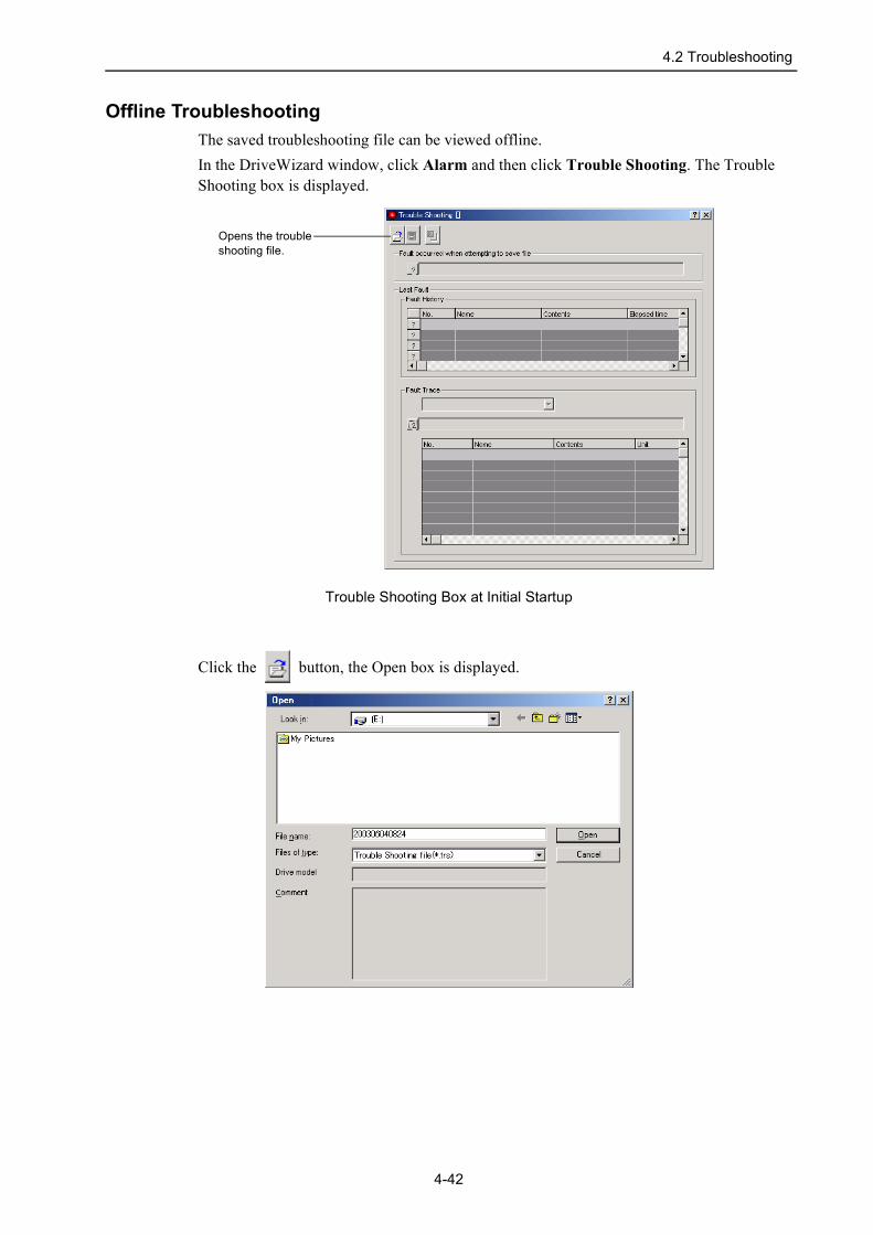
Offline TroubleshootingThe saved troubleshooting file can be viewed offline.In the DriveWizard window, click Alarm and then click Trouble Shooting. The Trouble Shooting box is displayed.
Trouble Shooting Box at Initial Startup
Click the button, the Open box is displayed.
Opens the trouble shooting file.
4-42

4.2 Troubleshooting
Click Open. The specified file is loaded and the Trouble Shooting box is displayed.
Trouble Shooting Box (Offline)
Note: Display contents differ depending on the Inverter type.
Fault occurred when attempting to save file
The alarm that was occurring when the file was saved is displayed.
Click the button, to display details concerning a specific alarm and its corrective measures.
4-43

4.2 Troubleshooting
Last Fault
Note: The number of fault history to be stored differs depending on Inverter type. And also, the Elapsed time column is not displayed in some Inverter type.
<Fault Trace>The Inverter stores a history of the 10 most recent faults. In DriveWizard, these are displayed in the Fault History column in the Trouble Shooting box, and are shown in order of occurrence with their fault code, the details about the type of fault, such as name, and elapsed time at fault.
Click the button, to display details concerning a specific fault and its corrective measures.
<Fault Trace>The values of monitor items when the fault occurred are displayed. Select a last fault in the combo box.
Click the button, to display details concerning a specific fault and its corrective measures.
Fault trace function is not available for some Inverter type.
4-44

4.2 Troubleshooting
(Drive Type Info) button
Click the button, the Drive Type Info box is displayed.
Drive Type Info Tab Comment Tab
Comments can be typed in the comment tab.Click OK to save the typed comments.Click Cancel to cancel the typed comments.
4-45

4.2 Troubleshooting
(Save) button
Click the button, the Save As box is displayed.
Click Save to overwrite or save as another file the added or changed comment in the Drive Type Info box.Click Cancel to return to the Trouble Shooting box.
4-46

4.3.1 Product Information
4.3 Monitor4.3.1 Product Information
Information about the Inverter can be viewed in the Product Information window.In the DriveWizard main window, click Monitor and then click Product Information. Information about the Inverter will be displayed.
Product Information Window
Click the button to display the specifications for the product model.Click OK to return to the DriveWizard main window.
4-47

4.3.2 Monitor
4.3.2 MonitorThe Inverter’s status, movement, and I/O signal status, can be monitored on the computer screen.There are five types of monitor windows: Status Monitor, Motion Monitor, Input Signal Monitor, Output Signal Monitor, and All Monitor.With All Monitor, Inverter status, movement, and I/O signal status are displayed in one window.The monitor windows are independent of each other, but several windows can be displayed at the same time.Select the information to be monitored in the Monitor Item Setting box.
Monitor Item SettingTo select the information to be monitored, use the following procedure.
4-48

4.3.2 Monitor
1. In the DriveWizard main window, click Monitor, and then click Monitor Setting. The Monitor Item Setting box appears.
Monitor Item Setting Box
2. Select the tab for which you want to set monitor items.3. To display an item, select it in the Monitor Select list and then click Add.
Moves the selected
Moves the selected
Information to be
Informationnot displayedin the Monitorwindow
item up one level.
item down one level.
displayed in theMonitor window
4-49

4.3.2 Monitor
4. Click OK, and the five monitor windows appear showing the selected information.
To open the Monitor Item Setting window, right-click and click Monitor Item Setting. To move an item, right-click an item and select a command.
4-50

4.3.2 Monitor
Status MonitorTo monitor the status of the Inverter, use the following procedure.1. In the DriveWizard main window, click Monitor, point to Monitor and click Status
Monitor.
The items which can be monitored are listed.2. Select the items to be monitored. To select all items, select the All parameters check
box. The current status of a selected item is displayed in the "Value" column.
4-51

4.3.2 Monitor
Motion MonitorTo monitor the motions of the Inverter, use the following procedure.1. In the DriveWizard main window, click Monitor, point to Monitor and click Motion
Monitor.
The items which can be monitored are listed.2. Select the items to be monitored. To select all items, select the All parameters check
box. The current status of a selected item is displayed in the "Value" column.
Max: Displays the maximum value.Min: Displays the minimum value.Average: Displays the average value.To clear the values in the Max, Min, and Average columns, click Reset. After the columns are cleared, the display of the items being monitored starts again.
4-52

4.3.2 Monitor
Input Signal MonitorTo monitor the input signal of the Inverter, use the following procedure.1. In the DriveWizard main window, click Monitor, point to Monitor and click Input
Signal Monitor.
The items which can be monitored are listed.2. Select the items to be monitored. To select all items, select the All parameters check
box. The current status of a selected item is displayed in the "Value" column.
4-53
4.3.2 Monitor
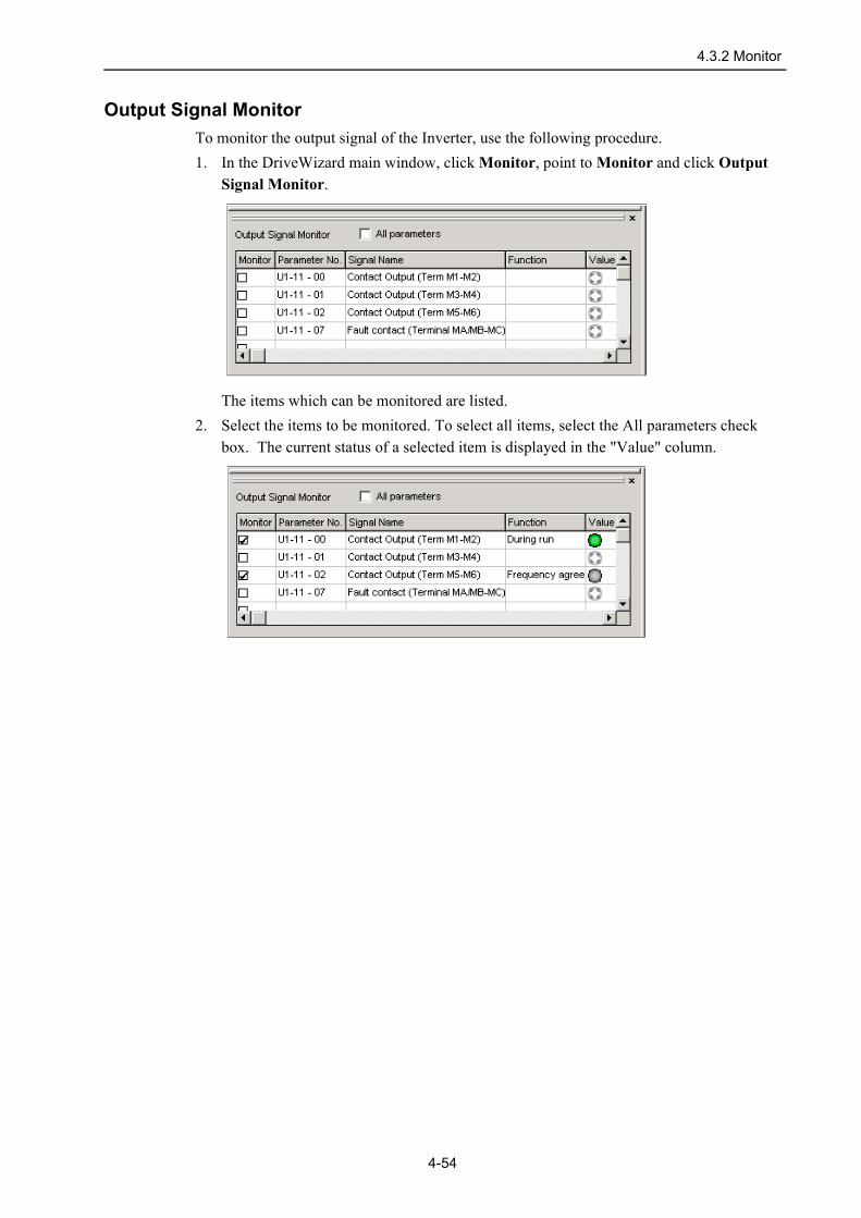
Output Signal MonitorTo monitor the output signal of the Inverter, use the following procedure.1. In the DriveWizard main window, click Monitor, point to Monitor and click Output
Signal Monitor.
The items which can be monitored are listed.2. Select the items to be monitored. To select all items, select the All parameters check
box. The current status of a selected item is displayed in the "Value" column.
4-54

4.3.2 Monitor
All MonitorTo monitor Inverter status, movement, and I/O signal status in one window, use the following procedure.1. In the DriveWizard main window, click Monitor, point to Monitor and click All
Monitor.
The items which can be monitored are listed.2. Select the items to be monitored. To select all items, select the All parameters check
box. The current status of a selected item is displayed in the "Value" column.
4-55

4.3.2 Monitor
Adding and Removing a Monitor AddressAny constant can be a monitor constant if its MEMOBUS address information is added to the monitor item. To add or remove the monitor address, use the following procedure.
1. In the DriveWizard main window, click Monitor and then click Monitor Setting. The Monitor Item Setting box appears.
Monitor Item Setting Box
2. Click Add/Remove Address, and the Add/Remove Monitoring Address box appears.
4-56

4.3.2 Monitor
3. Enter the value for each items, click Add. If the MEMOBUS address is available, it is displayed in the Monitor entry list. If it is not available, the following message appears.
4. Click OK, and return to the Monitor Item Setting box, where the MEMOBUS address is displayed in the Monitor select list.
4-57

4.3.3 Oscilloscope Function
4.3.3 Oscilloscope FunctionInverter items to be monitored can be displayed in graph in real time.
Data Monitor
Main WindowIn the DriveWizard main window, click Monitor, and then click Oscilloscope, and the Oscilloscope main window appears.
Oscilloscope Main Window
4-58

4.3.3 Oscilloscope Function
Oscilloscope SettingsIn the Oscilloscope main window, click SETUP, and the Oscilloscope Setting box appears. Select the objects and conditions for the monitor.The settings from the previous monitor, if any, are displayed.
Oscilloscope Setting Box
OKIn the Oscilloscope Setting box, click OK to return to the Oscilloscope main window. The monitor data are updated according to the settings.
CancelIn the Oscilloscope Setting box, click Cancel to return to the Oscilloscope main window without changing the settings.
<Monitor Object Settings>
CH1/CH2Select content such as "Output frequency", "Frequency Reference", etc., as monitor objects from the data boxes.
Line Select a line color for data 1 and 2.
4-59

4.3.3 Oscilloscope Function
<Saves File>Selects whether to save the sampling data or not.Note: To save the data, be sure 30 Mbyte of free hard disk space are available. As a guideline, about 2 Mbyte of
free hard disk space is needed to save one hour of normal data.
If not saving the data, select the Not Save check box. If saving the data, click to clear the Not Saved check box and click Setting. The Save As box is displayed.
Designate the file to save the data, and click Save. Click Cancel to return to the Oscilloscope Setting box without saving the file.If the file name already exists or if an already existing file is loaded and then re-saved, a warning message appears, telling you that the file name already exists, and asks if you want to replace the existing file.
Click Yes to overwrite the already existing file. Click No to return to the Save as box.
4-60

4.3.3 Oscilloscope Function
Starting the MonitorIn the Oscilloscope main window, click START to start monitoring.
To stop monitoring, click STOP.
To make the settings for the sampling data, click Setting. The Sampling data setting box is displayed.
Displays the current measurement and the maximum, minimum, and average values of each item.
hour minute second
4-61

4.3.3 Oscilloscope Function
<Measurement>To clear the values of the table of the sampling data, click Resetting. After the table is cleared, the collection of the data for the items being monitored starts again.
<Average applicable range>Enter the time allowed to measure the maximum, minimum, and average values, and click Apply. After the table is cleared, the collection of the data for the items being monitored for the specified time starts.
(Example) When range 10 seconds.0 1 5 1011 15
second
10 seconds later: Maximum, minimum, and average values between 0 to 10 seconds.11 seconds later: Maximum, minimum, and average values between 1 to 11 seconds.15 seconds later: Maximum, minimum, and average values between 5 to 15 seconds.
4-62

4.3.3 Oscilloscope Function
Main WindowThis Oscilloscope main window displays a graph based on the oscilloscope settings.
Oscilloscope Main Window
Displays information about when the monitor started.In this example for the displayed data, "0001" meansthat it is the first day of the trace and "01" means thatthe trace has been running for its first hour.
4-63

4.3.3 Oscilloscope Function
ToolbarThe position of the toolbar can be adjusted, and the on-screen display type selected.
Oscilloscope Main Window Toolbar
See " Toolbar Details" for details on the toolbar buttons.
Toolbar Button Click this button to:
Open
Load the monitor data file.
Print the Oscilloscope main window.
Measurement Conditions
View the conditions for monitoring.
Cursor
View the information for the location where a cursor is shown.
Parameter Online Editing
View the Parameter Online Editing box. For details, see Section 4.1.2.
Zoom In
Enlarge the view of a selected area.
Return
Restore the area shown in the window to its usual size.
Clipboard Copy
Copy the displayed screen to the clipboard.
Manual Operation
View the Manual Operation box. For details, see Section 4.5.1.
Monitor Item Setting
View the Monitor Item Setting window. For details, see Section 4.3.2.
4-64
4.3.3 Oscilloscope Function
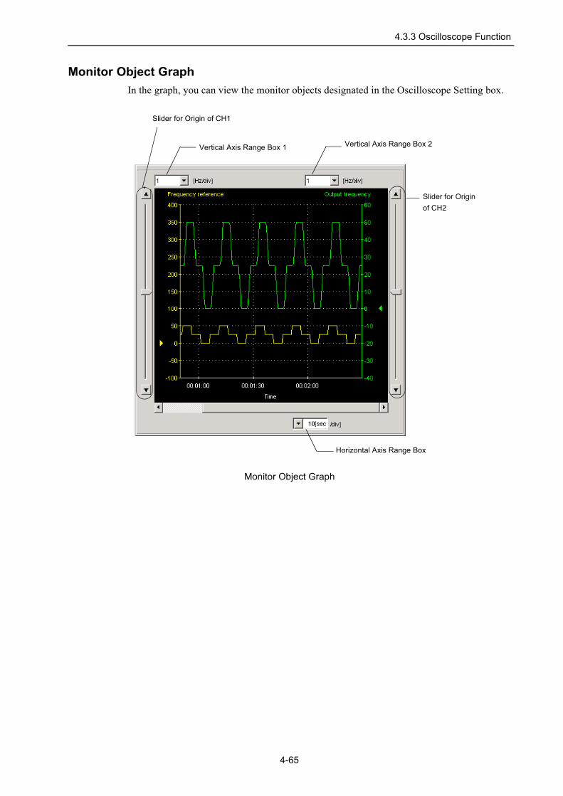
Monitor Object GraphIn the graph, you can view the monitor objects designated in the Oscilloscope Setting box.
Monitor Object Graph
Vertical Axis Range Box 1 Vertical Axis Range Box 2
Slider for Origin of CH1
Slider for Origin of CH2
Horizontal Axis Range Box
4-65

4.3.3 Oscilloscope Function
Vertical Axis RangeIn the Vertical axis range box 1.2, select each unit of CH1 and CH2.If AUTO is selected, the range widths will be automatically adjusted so that all of the data can be shown in the graph.The range must be selected from the list.
Vertical Axis Range Box
Horizontal Axis RangeIn the Horizontal axis range box, select the units of time for the time axis in the graph. If the maximum settings of “6 min” is selected, the data for one hour is displayed in the graph. This is the maximum amount of time that can be displayed in the window. The range must be selected from the list.
Horizontal Axis Range Box
4-66

4.3.3 Oscilloscope Function
Toolbar Details
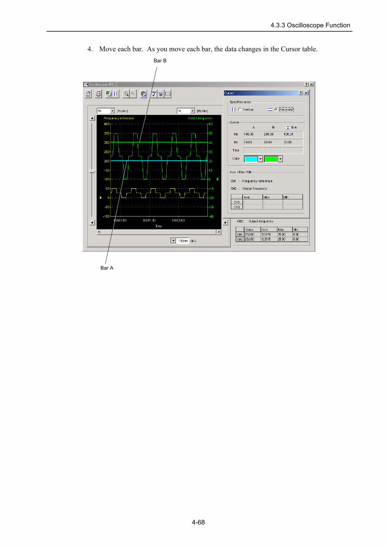
(Cursor) ButtonThe information for the location of each bar A and B can be viewed. In the window, the bars are referred to as cursors.The color of bars A and B can be changed.View the data using the following procedure.
1. Click the button. Two vertical bars will be displayed.2. Move each bar. As you move each bar, the data changes in the Cursor table.
3. To view the frequency data, select Horizontal in the Specifies axes area. Two horizontal bars will be displayed.
Bar A Bar B
Displays the maximum, minimum, and average values of CH1 and CH2 between A and B bars.
4-67
4.3.3 Oscilloscope Function
4. Move each bar. As you move each bar, the data changes in the Cursor table.Bar B
Bar A
4-68

4.3.3 Oscilloscope Function
(Zoom) ButtonA view of an area selected by the mouse can be magnified. Zoom in on an area using the following procedure.
1. Click the button.2. Position the mouse at one corner of the area you want to select, and drag to the opposite
corner. A line will appear around the selected area.
Area to be Magnified
Area Designated by the Mouse
4-69

4.3.3 Oscilloscope Function
3. Release the left mouse button. The selected area of the graph is enlarged.
Magnified Area
4. Click the button to view the original graph.
The graph will change in stages. To return to the original graph, click the button several times.
4-70

4.3.3 Oscilloscope Function
(Open) Button
The oscilloscope data file can be loaded in the Open box. To load the file, click the button. The Open box appears.
When the Button is Clicked in the Oscilloscope Main Window
OpenClick Open to load the selected oscilloscope file. Returns to the Oscilloscope main window if nothing is selected.
CancelClick Cancel to return to the Oscilloscope main window without loading the file.
4-71
4.3.3 Oscilloscope Function
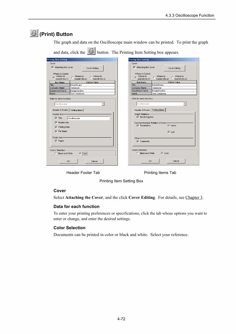
(Print) ButtonThe graph and data on the Oscilloscope main window can be printed. To print the graph
and data, click the button. The Printing Item Setting box appears.
Header Footer Tab Printing Items Tab
Printing Item Setting Box
CoverSelect Attaching the Cover, and the click Cover Editing. For details, see Chapter 3.
Data for each functionTo enter your printing preferences or specifications, click the tab whose options you want to enter or change, and enter the desired settings.
Color SelectionDocuments can be printed in color or black and white. Select your reference.
4-72

4.3.3 Oscilloscope Function
After setting is finished, click OK. The document appears on the screen the way it will appear in print.
To print the document as is without any changes, click the button.
To return to the Printing Item Setting box and change some settings, click Editing of the Printing Items.
4-73

4.3.3 Oscilloscope Function
(Measurement Conditions) Button
The conditions for monitoring can be viewed. To view the conditions, click the button. The Measurement Data box appears. If not already selected, click the Measurement Data tab to view the conditions for monitoring.
Measurement Data Tab
4-74

4.3.3 Oscilloscope Function
All Tab
4-75

4.3.3 Oscilloscope Function
Comment Tab
Click the Comment tab and type any comments.
OKClick OK to save comments and return to the Oscilloscope main window.Note: If “Not Saved” is selected in the Oscilloscope Setting box, the typed comments are
not saved.
CancelClick Cancel to return to the Oscilloscope main window without saving the comments.
4-76

4.3.3 Oscilloscope Function
(Clipboard Copy) ButtonThe displayed screen can be copied to the clipboard. It can be exported to other application programs by using this button.
Click the button, and the Clipboard Copy box appears.
Clipboard Copy Box
OKClick OK to copy the selected area to the clipboard.
CancelClick Cancel to return to the Oscilloscope main window.
Select the area to be copied to the clipboard.• Graph Area
4-77

4.3.3 Oscilloscope Function
• Whole Dialog
4-78

4.4 Motor Parameter Autotuning
4.4 Motor Parameter AutotuningMotor parameters can be turned using autotuning function (online) or auto parameter calculation (offline).
The motor will rotate during autotuning. Please read the user manual and check the following before operation.
• If executing standard autotuning, please verify the motor is disconnected from all machinery.• Please verify it is safe to rotate the motor.
Non-rotational autotuning will not turn the motor shaft. However, there will be some voltage applied to the motor. Please read the user manual and check the following before operation.
• Voltage is applied to the motor during non-rotational autotuning. Do not touch the motor until autotuning is complete.
• When using non-rotational autotuning with the motor connected to a load such as a conveyor, please use a mechanical brake during tuning to prevent unexpected rotation.
• When the drive is run for the first time after non-rotational autotuning, please keep the load less than 50%.
Non-rotational terminal resistance autotuning will not turn the motor shaft. However, there will be some voltage applied to the motor.Please read the user manual and check the following before operation.
• Voltage is applied to the motor during non-rotational terminal resistance autotuning.Do not touch the motor until autotuning is complete.
• When using non-rotational temrinal resistance autotuning with the motor connected to a load such as a conveyor, please use a mechanical brake during turning to prevent unexpected rotation.
! CAUTION
! CAUTION
! CAUTION
4-79

4.4 Motor Parameter Autotuning
Note: If a baseblock command of Multi-function contact input selection is being input from the external terminal, this function can not be performed.
Online Motor Parameter AutotuningPerform online motor parameter autotuning using the following procedure.1. In the DriveWizard main window, click Tuning and then click Motor Parameter
Autotuning. The following dialog box is displayed.
Standard Tuning: Rotational autotuning Automatically sets motor parameters while turning the motor. Use rotational autotuning whenever performing autotuning for a motor that has fixed output characteristics or for a motor that is not connected to a load.
Tune-No Rotate: Stationary autotuningAutomatically sets motor parameters while supplying power to the stationary motor.Use stationary autotuning whenever performing autotuning for a motor that is connected to a motor.
Auto parameter calculation should be used when the product does not have the autotuning func-tion or the motor cannot be disconnected from external machinery.Please carefully note the following.
• Performance may be inferior to a system which has been auto-tuned.• It is necessary to have motor nameplate data, the motor design sheet, or motor test report to use
vector control mode. If there is no motor data available, V/f control mode must be used.
! CAUTION
Opens help to show descriptions and precautions for each tuning mode.
4-80

4.4 Motor Parameter Autotuning
Term Resistance:Stationary autotuning for line-to-line resistance onlyAutomatically sets motor parameters while supplying power to the stationary motor.This autotuning can be used to prevent control errors when the motor cable is long or the cable length has changed or when the motor and Inverter have different capacities.
Calculation: Auto parameter calculationCalculates motor parameters from the value of the motor nameplate or test report.Only “Hz” is available for the constants related to frequency.
2. Select the motor in the Motor selection combo box. The tuning mode that is available for the selected motor is enabled.
3. Select the tuning mode and click Next. The following dialog box is displayed.Note: Tuning mode that can be selected differs depending on the Inverter type or control mode. Refer to the
instruction manual for the details.
Note: Caution contents differ depending on the tuning mode.
Click Cancel to cancel autotuning, and return to the DriveWizard main window.
4-81

4.4 Motor Parameter Autotuning
4. Click Next, and the following dialog box is displayed.
Note: Setting items differ depending on the tuning mode.5. Enter each setting items required for tuning in the Value column.6. Click Next , and the following dialog box is displayed.
4-82
4.4 Motor Parameter Autotuning
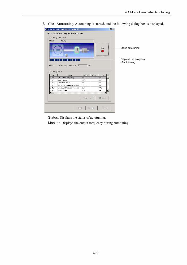
7. Click Autotuning. Autotuning is started, and the following dialog box is displayed.
Status: Displays the status of autotuning.Monitor: Displays the output frequency during autotuning.
Stops autotuning.
Displays the progress of autotuning.
4-83

4.4 Motor Parameter Autotuning
After autotuning is finished, the tuned values are displayed in the After column of the Autotuning results list. Values that differ from the values before autotuning are displayed in red.
Click Back to return to the tuning motor data set box.Click Cancel to change the tuned values back to their original values and return to the DriveWizard main window.
8. Click Complete to save the tuned values to the Inverter and return to the DriveWizard main window.
Saves tuned constants and constants needed for autotuning in a text format.
Saves all constants in a file.
4-84

4.4 Motor Parameter Autotuning
Offline Motor Parameter AutotuningPerform offline motor parameter autotuning using the following procedure.1. In the DriveWizard main window, click Tuning and then click Motor Parameter
Autotuning. The following dialog box is displayed.
Open file: Reads in existing parameters.Create new file: Creates new setting for parameters.
2. Select the desired command and click OK.
<When “Open file” is Selected>When “Open file” is selected, the Open box appears.
Select the file to be imported, and click Open.
4-85

4.4 Motor Parameter Autotuning
<When “Open new file” is Selected>When “Open new file” is selected, the Drive mode selection box appears.
Select the model of Inverter and the area. And type the last four digits of the software number. Click Next to continue, and the Mode selection box appears.Note: Check the software number by checking the nameplate or using the digital operator. Refer to the
Inverter instruction manuals for more information.
4-86

4.4 Motor Parameter Autotuning
Select the value in each list box. Or click each Edit button and type the value. Click Apply. The following dialog box is displayed.
Calculation: Auto parameter calculationCalculates motor parameters from the value of the motor nameplate or test report.Only “Hz” is available for the constants related to frequency.
3. Select the motor in the Motor selection combo box, and click Calculation. The following dialog box is displayed.
Click Cancel to cancel autotuning, and return to the DriveWizard main window.
Opens help to show descriptions and precautions for auto parameter calculation.
4-87

4.4 Motor Parameter Autotuning
4. Click Next, and the following dialog box is displayed.
5. Enter each setting items required for tuning in the Value column.6. Click Next and the following dialog box is displayed.
4-88

4.4 Motor Parameter Autotuning
7. Click Autotuning. Tuning is started, and the following dialog box is displayed.
Status: Displays the status of tuning.
After tuning is finished, the tuned values are displayed in the After column of the Autotuning results list. Values that differ from the values before tuning are displayed in red.
Click Back to return to the tuning motor data set box.
Stops tuning.
Displays the progress of tuning.
Saves tuned parameters and parameters needed for tuning in a text format.
Saves all parameters in a file.
4-89

4.4 Motor Parameter Autotuning
8. Save the tuning results using either of the following methods.
<When saving all parameters>Click Save, and the Save As box is displayed.
Click Save.
<When saving tuned parameters and parameters needed for tuning>Click Save text and the Save As box is displayed.
Click Save.
4-90

4.5.1 Manual Operation
4.5 Test Run4.5.1 Manual Operation
This function turns the motor at the set speed. The rotational direction and the speed setting can be verified without connecting an upper-level controller.
Notes: 1. If a baseblock command of Multi-function contact input selection is being input from the external terminal, this function can not be performed.
2. For manual operations with the VarispeedG5 Inverter, set the Frequency of the reference setting and the monitor (o1-03) to 0.01 Hz units (factory setting).
Manual operation will cause the motor to rotate and can be dangerous.Be sure to check the user’s manual before execution.Pay particular attention to the following items.
• Check the safety of the area around the drive unit.
The motor runs at the set speed while the Forward or Reverse button is pressed. Make sure that the surrounding area is clear of any items that could interfere with the running of the motor.
• Assign the Emergency Stop to the external terminal.
If a communications error occurred or the PC or DriveWizard is shut down because of an error during a manual operation, the motor may continue to rotate. To stop the motor, use the Emer-gency Stop.
• Please only use DriveWizard for changing inverter parameters.
If a parameter (such as frequency units) is changed by any method other than DriveWizard, the motor speed can suddenly change and result in injury.
• Reset the parameters to their original setting after an error. (V7, J7, G5)
This feature will change the RUN source selection paramater temporarily. (RUN command selec-tion, Frequency reference selection)After a communications error occurred or the PC or DriveWizard is shut down because of an error during a manual operation, reset the parameters for the operation method and reference selections to their original settings.
• Restart the Inverter after an error. (G7, F7, L7)
This feature will change the RUN source selection paramater temporarily. (ComCtrl, ComNet)After a communications error occurred or the PC or DriveWizard is shut down because of an error during a manual operation, restart the Inverter.
• Recommendations for using DriveWizard
Use DriveWizard for inverter setup and run test.Disconnect the motor from the load when using manual operation mode.
! WARNING
4-91

4.5.1 Manual Operation
The following conditions must be satisfied to carry out a manual operation.• Remote is selected with the LOCAL/REMOTE key of the Digital Operator or in Multi-
function contact input function.• A fault is not detected.• The Motor is not running.
Perform a manual operation using the following procedure.1. In the DriveWizard main window, click Test Run, and then click Manual Operation.
A warning message appears reminding you of the dangers that are possible when using this operation.
Note: Caution contents differ depending on the Inverter type.
Click Cancel to return to the main window without performing a manual operation.
4-92
4.5.1 Manual Operation
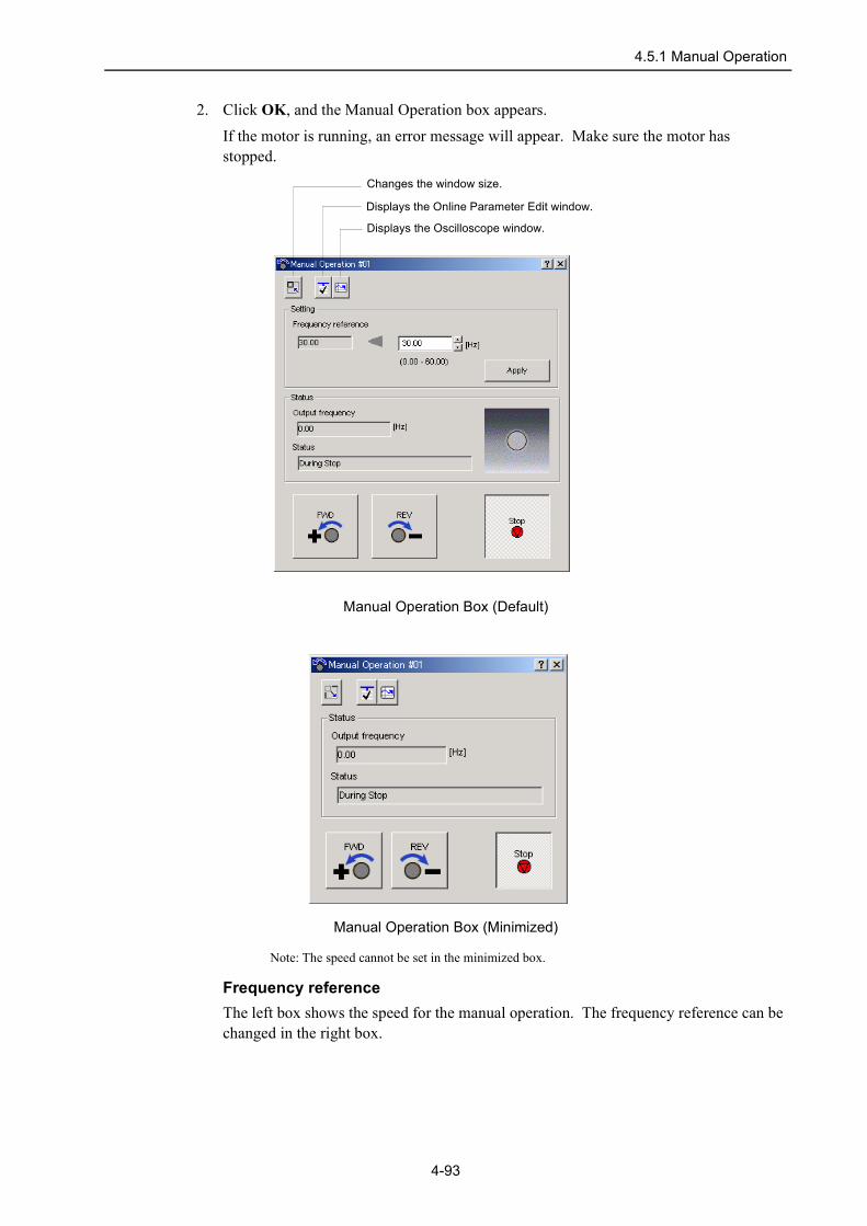
2. Click OK, and the Manual Operation box appears.
If the motor is running, an error message will appear. Make sure the motor has stopped.
Manual Operation Box (Default)
Manual Operation Box (Minimized)
Note: The speed cannot be set in the minimized box.
Frequency referenceThe left box shows the speed for the manual operation. The frequency reference can be changed in the right box.
Displays the Oscilloscope window.
Displays the Online Parameter Edit window.
Changes the window size.
4-93

4.5.1 Manual Operation
Output frequencyThe output frequency box shows the actual running speed.
StatusThe status box shows the Inverter status: During Forward Run, During Reverse Run, During Stop, Zero-speed, error, or Drive is not ready.
3. Check the speed for a manual operation. To change the speed, enter the frequency reference in the right Frequency reference box by typing or using the spin button and click Enter. The new speed will be displayed in the left Frequency reference box.
4. Click Forward Run or Reverse Run. A manual operation can be performed only while one of these buttons is pressed in.
Forward Run Reverse Run
Note: The screen shots show the motor running by a forward run command or a reverse run command. The actual direction depends on the motor wiring or the parameter setting.
4-94

4.5.2 Pattern Operation
4.5.2 Pattern OperationThis function turns the motor in the set operation pattern.
Pattern operation will cause the motor to rotate and can be dangerous.Be sure to check the user’s manual before execution.Pay particular attention to the following items.
• Check the safety of the area around the drive unit.
The motor runs at the set speed while the Forward or Reverse button is pressed. Make sure that the surrounding area is clear of any items that could interfere with the running of the motor.
• Assign the Emergency Stop to the external terminal.
If a communications error occurred or the PC or DriveWizard is shut down because of an error during a pattern operation, the motor may continue to rotate. To stop the motor, use the Emer-gency Stop.
• Please only use DriveWizard for changing inverter parameters.
If a parameter (such as frequency units) is changed by any method other than DriveWizard, the motor speed can suddenly change and result in injury.
• Reset the parameters to their original setting after an error. (V7, J7, G5)
This feature will change the RUN source selection paramater temporarily. (RUN command selec-tion, Frequency reference selection)After a communications error occurred or the PC or DriveWizard is shut down because of an error during a pattern operation, reset the parameters for the operation method and reference selections to their original settings.
• Restart the Inverter after an error. (G7, F7, L7)
This feature will change the RUN source selection paramater temporarily. (ComCtrl, ComNet)After a communications error occurred or the PC or DriveWizard is shut down because of an error during a pattern operation, restart the Inverter.
• Use care when using pattern operation mode with positioning applications.
Use care when using pattern operation mode with positioning applications. As there is no position feedback, make sure that there are no alignment/position problems with the machinery. Running the motor for an extended period of times when such problems exist can be dangerous and cause damage.
• Regards display of operations while running.
This function displays the operational status while the drive is running, although there are times when the motor operations and the time chart will not match due to various factors such as sur-rounding environment. Please do not rely completely on the time chart.
• Recommendations for using DriveWizard
Use DriveWizard for inverter setup and run test.Disconnect the motor from the load when using pattern operation mode.
! CAUTION
4-95

4.5.2 Pattern Operation
Notes: 1. If a baseblock command of Multi-function contact input selection is being input from the external terminal, this function can not be performed.
2. The pattern operation is based on the settings, Acceleration/deceleration time 1 and Motor 1, of the multi-function contact input selections. Acceleration/deceleration time 2, 3 and Motor 2 selections are not available in the pattern operation.
3. For pattern operations with the VarispeedG5 Inverter, set the Frequency of reference setting and the monitor (o1-03) to 0.01 Hz units (factory setting).
Perform a pattern operation using the following procedure.
1. In the DriveWizard main window, click Test Run, and then click Pattern Operation. A warning message appears reminding you of the dangers that are possible when using this operation.
Note: Caution contents differ depending on the Inverter type.
Click Cancel to return to the DriveWizard main window without performing a pattern operation.
4-96

4.5.2 Pattern Operation
2. Click OK, and the Pattern Operation box is displayed.
Pattern Operation Box (Default)
Pattern Operation Box (Minimized)
Note: The operation pattern cannot be set in the minimized box.
Displays the Oscilloscope window.
Displays the Online Parameter Edit window
Saves pattern operation data to a file.
Opens a pattern operation file.
Changes the window size.
4-97

4.5.2 Pattern Operation
3. Enter each item for operation conditions in the Run Pattern area, click Apply. The operation pattern is displayed in a graph.
The line in the graph corresponding to the selected operation pattern in the operation pattern area is displayed in red.
<If the Inverter is not set to stop at the end in the set operation pattern>If the Inverter is not set to stop at the end in the set operation pattern, the following dialog box is displayed.
Click Yes to reset the operation pattern to zero-speed automatically.Click No to return to the Pattern Operation box and set the operation pattern again.
Vertical Axis Range Box
Horizontal Axis Range Box
4-98
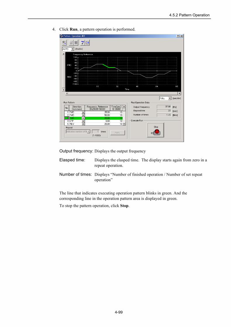
4.5.2 Pattern Operation
4. Click Run, a pattern operation is performed.
Output frequency: Displays the output frequency
Elasped time: Displays the elasped time. The display starts again from zero in a repeat operation.
Number of times: Displays “Number of finished operation / Number of set repeat operation”
The line that indicates executing operation pattern blinks in green. And the corresponding line in the operation pattern area is displayed in green.
To stop the pattern operation, click Stop.
4-99

4.5.2 Pattern Operation
(Open) button
The pattern operation file can be loaded in the Open box.
1. Click the button, the Open box appears.
<If an operation pattern is being edited>If an operation pattern is being edited, a message appears and confirms if you want to save the current settings.
Click OK to save the current settings.Click No to overwrite the current settings without saving the current settings.Click Cancel to return to the Operation Pattern box.
2. Select the file to be loaded, and click Open. The Operation Pattern box is displayed.
If the following items differ between in the specified file and in the current settings, the following dialog box is displayed.• Acceleration time• Deceleration time • Accel/decel time setting unit• Display scaling
4-100

4.5.2 Pattern Operation
Click OK to continue loading the file. After the loading is finished, check the values of those parameters.
(Save) button
The operation pattern data can be saved in a specified file.
Click the button, and the Save As box is displayed.
Click Save, and operation pattern data is saved in the specified file.Click Cancel to return to the Pattern Operation box.
4-101

5-1
5 Technical SupportIRUMA BUSINESS CENTER (SOLUTION CENTER)480, Kamifujisawa, Iruma, Saitama 358-8555, JapanPhone 81-4-2962-5696 Fax 81-4-2962-6138
YASKAWA ELECTRIC AMERICA, INC.2121 Norman Drive South, Waukegan, IL 60085, U.S.A.Phone 1-847-887-7000 Fax 1-847-887-7370
YASKAWA ELETRICO DO BRASIL COMERCIO LTD.A.Avenida Fagundes Filho, 620 Bairro Saude-Sao Paulo-SP, Brazil CEP: 04304-000Phone 55-11-5071-2552 Fax 55-11-5581-8795
YASKAWA ELECTRIC EUROPE GmbHAm Kronberger Hang 2, 65824 Schwalbach, GermanyPhone 49-6196-569-300 Fax 49-6196-569-312
YASKAWA ELECTRIC UK LTD.1 Hunt Hill Orchardton Woods Cumbernauld, G68 9LF, United KingdomPhone 44-1236-735000 Fax 44-1236-458182
YASKAWA ELECTRIC KOREA CORPORATION7F, Doore Bldg. 24, Yeoido-dong, Youngdungpo-Ku, Seoul 150-877, KoreaPhone 82-2-784-7844 Fax 82-2-784-8495
YASKAWA ELECTRIC (SINGAPORE) PTE. LTD.151 Lorong Chuan, #04-01, New Tech Park 556741, SingaporePhone 65-6282-3003 Fax 65-6289-3003
YASKAWA ELECTRIC (SHANGHAI) CO., LTD.No.18 Xizang Zhong Road. Room 1702-1707, Harbour Ring Plaza Shanghai 200001, ChinaPhone 86-21-5385-2200 Fax 86-21-5385-3299
YASKAWA ELECTRIC (SHANGHAI) CO., LTD. BEIJING OFFICERoom 1011A, Tower W3 Oriental Plaza, No.1 East Chang An Ave.,Dong Cheng District, Beijing 100738, ChinaPhone 86-10-8518-4086 Fax 86-10-8518-4082
YASKAWA ELECTRIC TAIWAN CORPORATION9F, 16, Nanking E. Rd., Sec. 3, Taipei, TaiwanPhone 886-2-2502-5003 Fax 886-2-2505-1280

Revision History
The revision dates and numbers of the revised manuals are given on the bottom of the front cover.
Date of Printing Rev. No. Section Revised Content
April 2006 − First edition
MANUAL NO. TOEPC73060017A
April 2006 06-4C
Date of printing
Date of original publication