Embed Size (px)
Citation preview

SP605 Built-In Self Test Flash Application
December 2009
© Copyright 2009 Xilinx XTP062

Overview
Xilinx SP605 BoardSoftware RequirementsSP605 SetupSP605 BIST (Built-In Self Test) Compile SP605 BIST DesignProgram SP605 BPIReferences
Note: This presentation applies to the SP605

SP605 BIST Design Description
Description– The Built-In System Test (BIST) application uses an EDK MicroBlaze system
to verify board functionality. A UART based terminal program interface offers users a menu of tests to run.
Reference Design IP– EDK IP: MicroBlaze, plb_v46, lmb_v10, mdm, lmb_bram_if_cntlr,
bram_block, xps_bram_if_cntlr, xps_uart16550, xps_gpio, clock_generator, mpmc, proc_sys_reset, xps_intc, xps_timer, xps_iic, xps_mch_emc, xps_spi, util_io_mux, util_bus_split, xps_ethernetlite
• Embedded System Tools Reference Guide (UG111)• http://www.xilinx.com/ise/embedded/edk_ip.htm
Reference Design Source– rdf0045.zip
Note: Presentation applies to the SP605
Embedded Processor Design
The provided embedded reference design is supported “as is”– Please refer to the click through license agreement
Embedded reference design has been verified on the SP605 Evaluation Kit– Design consists of Early Access IP– Design may change in subsequent releases
The reference design will allow users to:– Re-build and verify functionality on the SP605 evaluation kit
Note: Presentation applies to the SP605
SP605 MicroBlaze Hardware
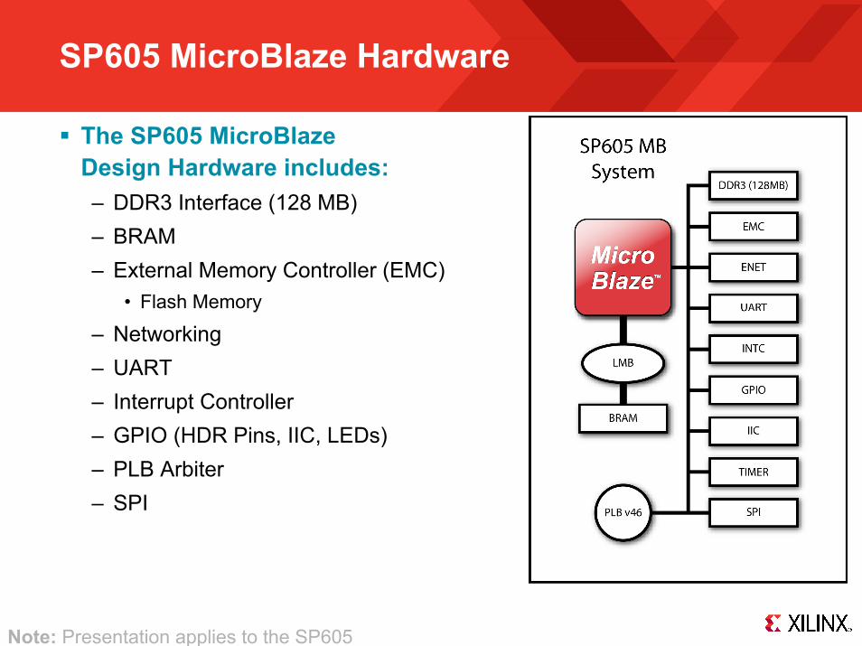
The SP605 MicroBlaze Design Hardware includes:– DDR3 Interface (128 MB)– BRAM – External Memory Controller (EMC)
• Flash Memory
– Networking – UART– Interrupt Controller– GPIO (HDR Pins, IIC, LEDs)– PLB Arbiter– SPI
Note: Presentation applies to the SP605

Xilinx SP605 Board
Note: Presentation applies to the SP605

ISE Software Requirement
Xilinx ISE 11.4 software
Note: Presentation applies to the SP605
EDK Software Requirement
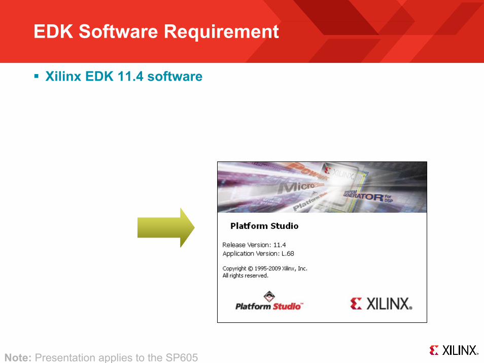
Xilinx EDK 11.4 software
Note: Presentation applies to the SP605

SP605 Setup
Power on the SP605 board for UART Drivers
Installation

Setup for the SP605 IBERT Designs
Connect a USB Type-A to Mini-B cable to the USB UART connector on the SP605 board– Connect this
cable to your PC

SP605 Setup
Install USB UART Drivers– https://www.silabs.com/Support Documents/Software/
CP210x_VCP_Win2K_XP_S2K3.zip
Note: Presentation applies to the SP605

SP605 Setup
Right-click on My Computer and select Properties– Select the Hardware tab– Click on Device Manager
Note: Presentation applies to the SP605

SP605 Setup
Expand the Ports Hardware– Right-click on Silicon Labs
CP210x USB to UART Bridge and select Properties
Note: Presentation applies to the SP605
SP605 Setup
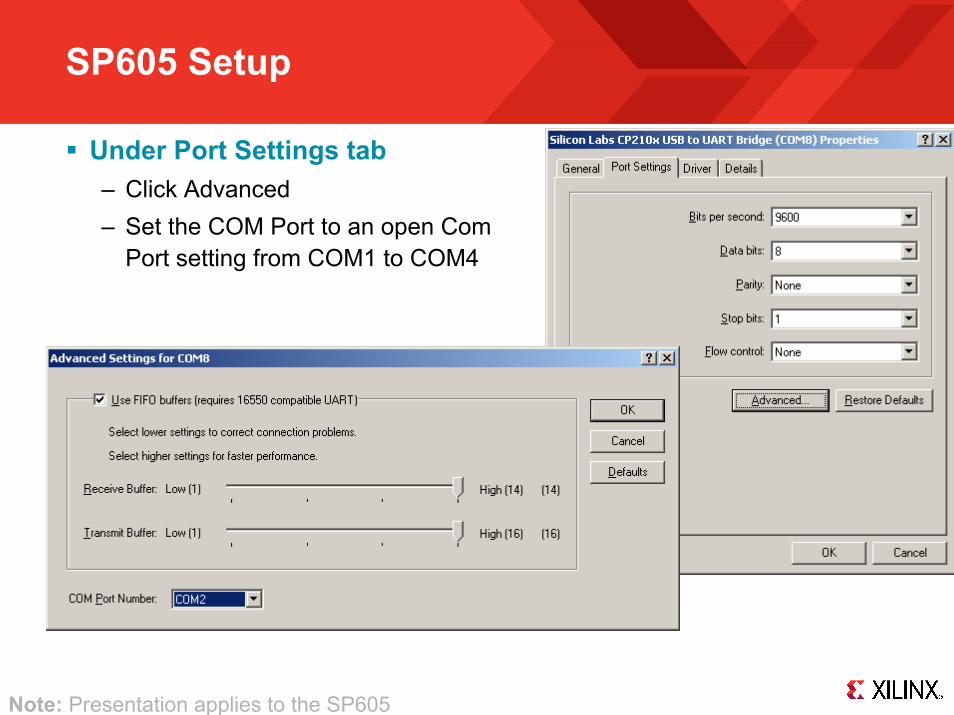
Under Port Settings tab– Click Advanced– Set the COM Port to an open Com
Port setting from COM1 to COM4
Note: Presentation applies to the SP605

SP605 Setup
Insert SP605 Evaluation Kit CompactFlash

SP605 Setup
Set the mode pins for System ACE
– M0 = 0– M1 = 1
– Set the System ACE SW1 to 0001 as shown

SP605 BIST Setup
Board Power must be on before starting Tera TermStart the Terminal Program– Select your USB Com Port– Set the baud to 9600
Note: Tera Term may need to be restarted if board power is cycled

SP605 BIST
Push SysACE Reset

SP605 BIST
Insert SP605 Evaluation Kit CompactFlash into the SP605Push SysACE Reset and view initial BIST screen– Type “1” to start the UART Test
Note: Presentation applies to the SP605

SP605 BIST
UART Test completed
Note: Presentation applies to the SP605

SP605 BIST
Output returns to initial menu after UART Test completes– Type 2 to begin LED Test
Note: Presentation applies to the SP605

View Walking 1’s pattern on GPIO LEDs– Sequence repeats six times
LED Test completed– Type 3 to begin Timer Test
SP605 BIST
Note: Presentation applies to the SP605

Output returns to initial menu after LED Test completes– Type 3 to begin Timer Test
SP605 BIST
Note: Presentation applies to the SP605
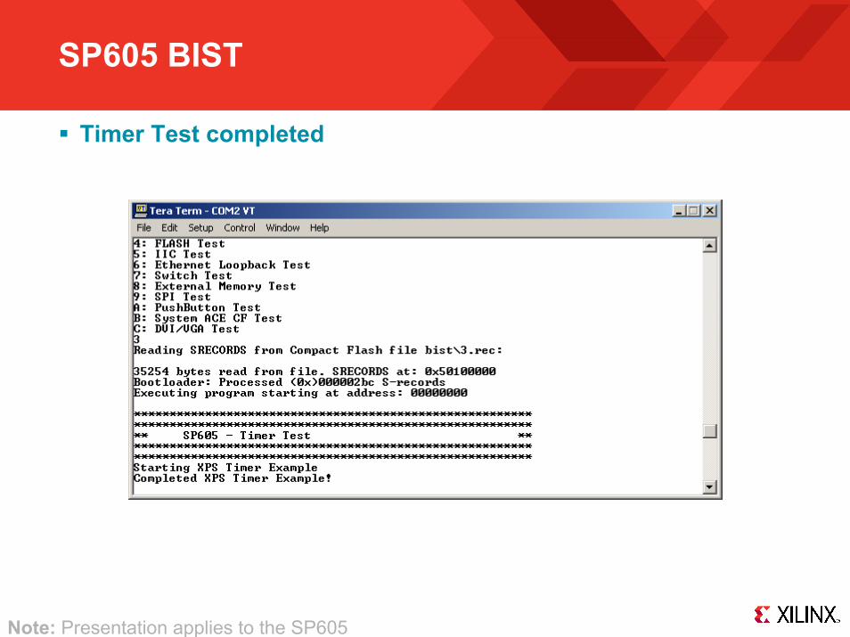
SP605 BIST
Timer Test completed
Note: Presentation applies to the SP605
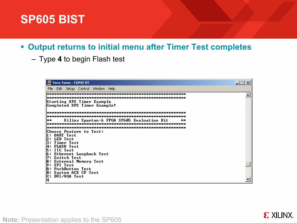
SP605 BIST
Output returns to initial menu after Timer Test completes– Type 4 to begin Flash test
Note: Presentation applies to the SP605
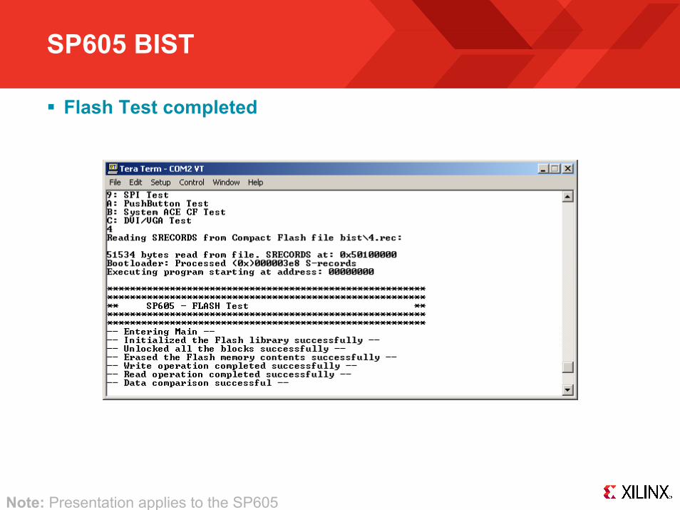
SP605 BIST
Flash Test completed
Note: Presentation applies to the SP605

SP605 BIST
Output returns to initial menu after Flash Test completes– Type 5 to begin IIC EEPROM Test
Note: Presentation applies to the SP605
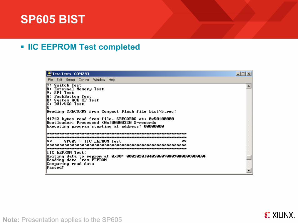
SP605 BIST
IIC EEPROM Test completed
Note: Presentation applies to the SP605

SP605 BIST
Output returns to initial menu after IIC EEPROM Test completes– Type 6 to begin Ethernet Loopback Test
• PHY is put into internal loopback mode
Note: Presentation applies to the SP605

SP605 BIST
Ethernet Loopback Test completed
Note: Presentation applies to the SP605

SP605 BIST
Output returns to initial menu after Ethernet Loopback Test completes
– Set 4-position GPIO DIP Switch (S2) – Type 7 to begin GPIO Switch Test
• Reads switch settings
Note: Presentation applies to the SP605

SP605 BIST
GPIO Switch Test completed
Note: Presentation applies to the SP605

SP605 BIST
Output returns to initial menu after GPIO Switch Test completes– Type 8 to begin External Memory Test
Note: Presentation applies to the SP605

SP605 BIST
External Memory Test running with caches on
Note: External Memory Test takes about 20 minutes

SP605 BIST
Second part of External Memory test (caches off)
Note: Presentation applies to the SP605

SP605 BIST
Output returns to initial menu after External Memory test completes– Type 9 to begin SPI Test
Note: Presentation applies to the SP605

SP605 BIST
SPI Test completed
Note: Presentation applies to the SP605

SP605 BIST
Output returns to initial menu after SPI Test completes– Type A to begin PushButton Test
Note: Presentation applies to the SP605

SP605 BIST
Push the Buttons in the order requested
Note: Presentation applies to the SP605

SP605 BIST
Output returns to initial menu after PushButton Test completes– Type B to begin System ACE CF Test
Note: Presentation applies to the SP605
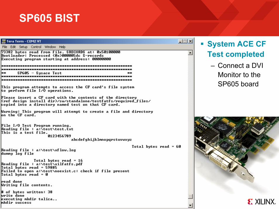
SP605 BIST
System ACE CF Test completed– Connect a DVI
Monitor to the SP605 board
SP605 BIST
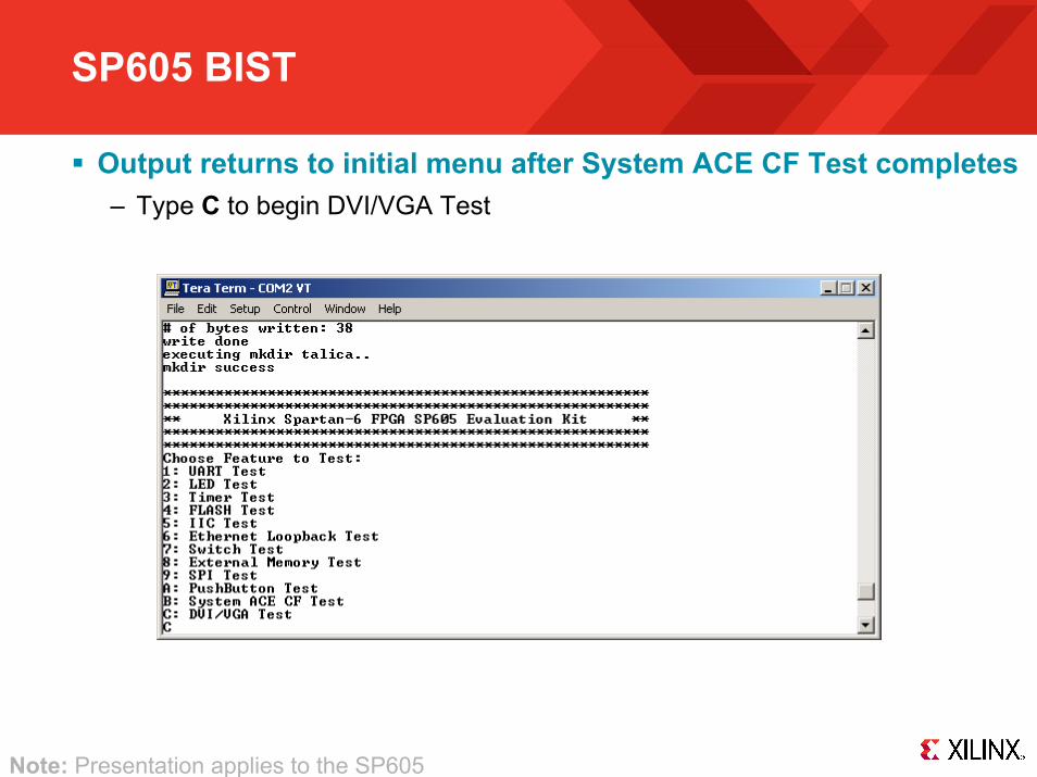
Output returns to initial menu after System ACE CF Test completes– Type C to begin DVI/VGA Test
Note: Presentation applies to the SP605

SP605 BIST
DVI/VGA Test completed
Note: Presentation applies to the SP605

Compile SP605 BIST Design

Compile SP605 BIST Design
Unzip the rdf0032.zip file– https://secure.xilinx.com/webreg/clickthrough.do?cid=140333
Note: Presentation applies to the SP605
Compile SP605 BIST Design
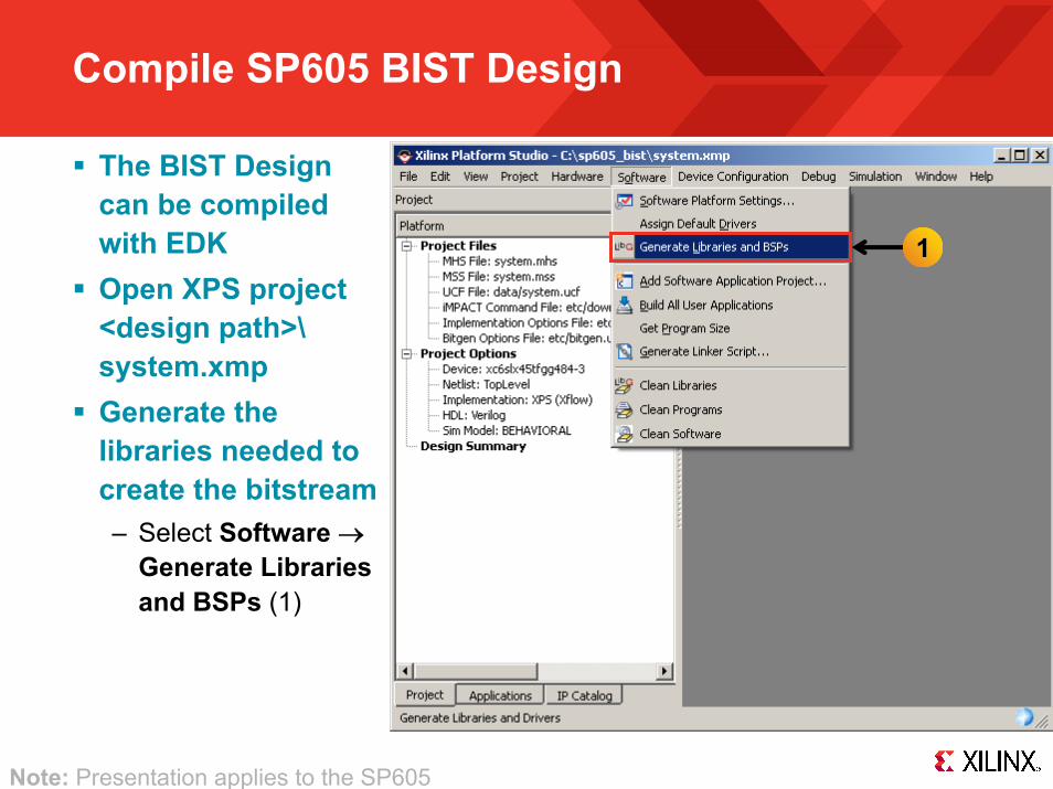
The BIST Design can be compiled with EDKOpen XPS project <design path>\system.xmpGenerate the libraries needed to create the bitstream– Select Software →
Generate Librariesand BSPs (1)
Note: Presentation applies to the SP605
1

Compile SP605 BIST Design
Compile the Software Applications and create the application ELF files– Select Software →
Build All User Applications (1)
Note: Presentation applies to the SP605
1

Compile SP605 BIST Design
Create the hardware design, system.bit, located in<project directory>/implementation– Select Hardware →
Generate Bitstream (1)
Note: Presentation applies to the SP605
1

Compile SP605 BIST Design
Init memorywith the Bootloader Application ELF– Update the bitstream
(download.bit) with the bootloader ELF (executable.elf)
– Select Device Configuration →Update Bitstream (1)
1
Note: Presentation applies to the SP605

Generate SP605 BIST Design CompactFlash
Convert the ELF files to S-record format and create ACE file– Select Project →
Launch Xilinx Bash Shell (1)
Note: Presentation applies to the SP605
1
Generate SP605 BIST Design CompactFlash
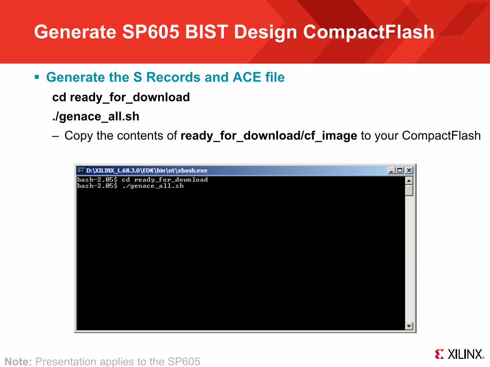
Generate the S Records and ACE filecd ready_for_download./genace_all.sh– Copy the contents of ready_for_download/cf_image to your CompactFlash
Note: Presentation applies to the SP605

References

References
EDK Documentation– Embedded System Tools Reference Guide
http://www.xilinx.com/support/documentation/sw_manuals/xilinx11/est_rm.pdf
System ACE CF– System ACE CompactFlash Solution
http://www.xilinx.com/support/documentation/boards_and_kits/ug080.pdf
Spartan-6 Configuration– Spartan-6 FPGA Configuration User Guide
http://www.xilinx.com/support/documentation/user_guides/ug380.pdf

Documentation

Documentation
Spartan-6– Spartan-6 FPGA Family
http://www.xilinx.com/products/spartan6/index.htm
SP605 Documentation– Spartan-6 FPGA SP605 Evaluation Kit
http://www.xilinx.com/products/devkits/EK-S6-SP605-G.htm– SP605 Hardware User Guide
http://www.xilinx.com/support/documentation/boards_and_kits/ug526.pdf– SP605 Reference Design User Guide
http://www.xilinx.com/support/documentation/boards_and_kits/ug527.pdf