Embed Size (px)
Citation preview
xPC Target™ 4Device Drivers
How to Contact MathWorks
www.mathworks.com Webcomp.soft-sys.matlab Newsgroupwww.mathworks.com/contact_TS.html Technical Support
[email protected] Product enhancement [email protected] Bug [email protected] Documentation error [email protected] Order status, license renewals, [email protected] Sales, pricing, and general information
508-647-7000 (Phone)
508-647-7001 (Fax)
The MathWorks, Inc.3 Apple Hill DriveNatick, MA 01760-2098For contact information about worldwide offices, see the MathWorks Web site.
xPC Target™ Device Drivers Guide
© COPYRIGHT 2007–2010 by The MathWorks, Inc.The software described in this document is furnished under a license agreement. The software may be usedor copied only under the terms of the license agreement. No part of this manual may be photocopied orreproduced in any form without prior written consent from The MathWorks, Inc.
FEDERAL ACQUISITION: This provision applies to all acquisitions of the Program and Documentationby, for, or through the federal government of the United States. By accepting delivery of the Programor Documentation, the government hereby agrees that this software or documentation qualifies ascommercial computer software or commercial computer software documentation as such terms are usedor defined in FAR 12.212, DFARS Part 227.72, and DFARS 252.227-7014. Accordingly, the terms andconditions of this Agreement and only those rights specified in this Agreement, shall pertain to and governthe use, modification, reproduction, release, performance, display, and disclosure of the Program andDocumentation by the federal government (or other entity acquiring for or through the federal government)and shall supersede any conflicting contractual terms or conditions. If this License fails to meet thegovernment’s needs or is inconsistent in any respect with federal procurement law, the government agreesto return the Program and Documentation, unused, to The MathWorks, Inc.
Trademarks
MATLAB and Simulink are registered trademarks of The MathWorks, Inc. Seewww.mathworks.com/trademarks for a list of additional trademarks. Other product or brandnames may be trademarks or registered trademarks of their respective holders.
Patents
MathWorks products are protected by one or more U.S. patents. Please seewww.mathworks.com/patents for more information.

Revision HistoryMarch 2007 Online only New for Version 3.2 (Release 2007a)September 2007 Online only Updated for Version 3.3 (Release 2007b)March 2008 Online only Updated for Version 3.4 (Release 2008a)October 2008 Online only Updated for Version 4.0 (Release 2008b)March 2009 Online only Updated for Version 4.1 (Release 2009a)September 2009 Online only Updated for Version 4.2 (Release 2009b)March 2010 Online only Updated for Version 4.3 (Release 2010a)September 2010 Online only Updated for Version 4.4 (Release 2010b)

Contents
Customizing xPC Target Drivers
1Introduction . . . . . . . . . . . . . . . . . . . . . . . . . . . . . . . . . . . . . . 1-2xPC Target Drivers . . . . . . . . . . . . . . . . . . . . . . . . . . . . . . . . 1-2When to Write Your Own Drivers . . . . . . . . . . . . . . . . . . . . 1-3Restrictions on Customizing xPC Target Drivers . . . . . . . . 1-3Expected Background . . . . . . . . . . . . . . . . . . . . . . . . . . . . . . 1-3Resources for Customizing xPC Target Drivers . . . . . . . . . 1-4What Makes Up an xPC Target Driver? . . . . . . . . . . . . . . . 1-6
Before You Start . . . . . . . . . . . . . . . . . . . . . . . . . . . . . . . . . . . 1-8Introduction . . . . . . . . . . . . . . . . . . . . . . . . . . . . . . . . . . . . . . 1-8Driver Types . . . . . . . . . . . . . . . . . . . . . . . . . . . . . . . . . . . . . 1-9Bus Types and Register Access . . . . . . . . . . . . . . . . . . . . . . 1-9Register Access . . . . . . . . . . . . . . . . . . . . . . . . . . . . . . . . . . . 1-10Inlining xPC Target Drivers . . . . . . . . . . . . . . . . . . . . . . . . . 1-10
Creating a Custom Driver . . . . . . . . . . . . . . . . . . . . . . . . . . 1-11
Debugging Notes . . . . . . . . . . . . . . . . . . . . . . . . . . . . . . . . . . 1-16
PCI Drivers
2PCI Bus Considerations . . . . . . . . . . . . . . . . . . . . . . . . . . . . 2-2Introduction . . . . . . . . . . . . . . . . . . . . . . . . . . . . . . . . . . . . . . 2-2PCI Configuration Space API . . . . . . . . . . . . . . . . . . . . . . . . 2-3Memory-Mapped Accesses . . . . . . . . . . . . . . . . . . . . . . . . . . 2-6I/O Port Accesses . . . . . . . . . . . . . . . . . . . . . . . . . . . . . . . . . . 2-6
Sample PCI Device Driver . . . . . . . . . . . . . . . . . . . . . . . . . . 2-8
v
ISA and PC/104 Drivers
3ISA and PC/104 Bus Considerations . . . . . . . . . . . . . . . . . 3-2Introduction . . . . . . . . . . . . . . . . . . . . . . . . . . . . . . . . . . . . . . 3-2I/O Mapped . . . . . . . . . . . . . . . . . . . . . . . . . . . . . . . . . . . . . . 3-2Memory Mapped . . . . . . . . . . . . . . . . . . . . . . . . . . . . . . . . . . 3-3
Masking Drivers
4Creating Driver Subsystem Masks . . . . . . . . . . . . . . . . . . 4-2
Driver Mask Guidelines . . . . . . . . . . . . . . . . . . . . . . . . . . . . 4-3
Cross-Block Checking . . . . . . . . . . . . . . . . . . . . . . . . . . . . . . 4-5
When You Are Done . . . . . . . . . . . . . . . . . . . . . . . . . . . . . . . . 4-6
Sample Driver Mask . . . . . . . . . . . . . . . . . . . . . . . . . . . . . . . 4-7
Interrupt Support
5xPC Target Interrupts . . . . . . . . . . . . . . . . . . . . . . . . . . . . . 5-2Introduction . . . . . . . . . . . . . . . . . . . . . . . . . . . . . . . . . . . . . . 5-2Interrupt Processing in the xPC Target Environment . . . . 5-2
Adding Interrupt Support . . . . . . . . . . . . . . . . . . . . . . . . . . 5-7Introduction . . . . . . . . . . . . . . . . . . . . . . . . . . . . . . . . . . . . . . 5-7Guidelines for Creating Interrupt Functions . . . . . . . . . . . 5-9Filling in the Driver board Structure . . . . . . . . . . . . . . . . . 5-10
vi Contents
Hook Function Prototypes — Alphabetical List . . . . . . . 5-15
Custom xPC Target Driver Notes
6S-Function Guidelines . . . . . . . . . . . . . . . . . . . . . . . . . . . . . 6-2
mdlStart and mdlTerminate Considerations . . . . . . . . . 6-4
DMA Considerations . . . . . . . . . . . . . . . . . . . . . . . . . . . . . . . 6-5
Passing Parameters . . . . . . . . . . . . . . . . . . . . . . . . . . . . . . . . 6-6
Accessing Registers . . . . . . . . . . . . . . . . . . . . . . . . . . . . . . . . 6-7I/O Space . . . . . . . . . . . . . . . . . . . . . . . . . . . . . . . . . . . . . . . . 6-7Memory-Mapped Space . . . . . . . . . . . . . . . . . . . . . . . . . . . . . 6-7
Creating Custom Drivers Using the xPC TargetDriver Authoring Tool
7xPC Target Driver Authoring Tool . . . . . . . . . . . . . . . . . . 7-2
Generating Custom Driver Templates . . . . . . . . . . . . . . . 7-4Using the xPC Target Driver Authoring Tool . . . . . . . . . . . 7-4Setting Up Driver Variables . . . . . . . . . . . . . . . . . . . . . . . . . 7-4Saving the Configuration . . . . . . . . . . . . . . . . . . . . . . . . . . . 7-7Reloading the Configuration . . . . . . . . . . . . . . . . . . . . . . . . 7-8Creating the C File Template . . . . . . . . . . . . . . . . . . . . . . . . 7-8Creating a C MEX File for the Driver . . . . . . . . . . . . . . . . . 7-8Customizing the Device Driver Mask . . . . . . . . . . . . . . . . . 7-9
vii
I/O Structures — By Category
8
I/O Structures — Alphabetical List
9
I/O Functions — By Category
10Port I/O . . . . . . . . . . . . . . . . . . . . . . . . . . . . . . . . . . . . . . . . . . . 10-2
PCI Configuration Information . . . . . . . . . . . . . . . . . . . . . 10-2
Physical Memory . . . . . . . . . . . . . . . . . . . . . . . . . . . . . . . . . . 10-2
Time . . . . . . . . . . . . . . . . . . . . . . . . . . . . . . . . . . . . . . . . . . . . . . 10-2
Miscellaneous . . . . . . . . . . . . . . . . . . . . . . . . . . . . . . . . . . . . . 10-3
I/O Functions — Alphabetical List
11
viii Contents
1
Customizing xPC TargetDrivers
• “Introduction” on page 1-2
• “Before You Start” on page 1-8
• “Creating a Custom Driver” on page 1-11
• “Debugging Notes” on page 1-16
1 Customizing xPC Target™ Drivers
Introduction
In this section...
“xPC Target Drivers” on page 1-2
“When to Write Your Own Drivers” on page 1-3
“Restrictions on Customizing xPC Target Drivers” on page 1-3
“Expected Background” on page 1-3
“Resources for Customizing xPC Target Drivers” on page 1-4
“What Makes Up an xPC Target Driver?” on page 1-6
xPC Target DriversThe xPC Target™ software provides device drivers for a variety of third-partyboards. xPC Target users access these drivers as Simulink® blocks fromthe xPC Target library (xpclib). If you have a board for which the xPCTarget software does not supply a driver, you can write your own. This guideprovides guidelines for writing custom xPC Target device drivers.
The xPC Target driver library contains drivers that support third-partyboards with many I/O capabilities and applications. This includes drivers fordifferent types of I/O boards, including
Analog-to-digitalDigital-to-analogAudioCountersShared memory
There are also drivers that support particular protocols, including
RS-232, RS-422, RS-485GPIBCANUDPARINC 429MIL-1553
1-2
Introduction
When to Write Your Own DriversConsider writing your own device drivers for the xPC Target block library if:
• No xPC Target driver exists for your I/O needs.
• You are unable to use a board that the xPC Target software supports.
• You need to extend the functionality of an existing xPC Target driver.
• The MathWorks xPC Target team will not write a device driver for yourboard.
Restrictions on Customizing xPC Target DriversThe xPC Target software has its own kernel, and you will be writing devicedrivers aimed at that kernel. An xPC Target driver is therefore differentfrom a driver for another environment, such as Microsoft Windows. The xPCTarget kernel is optimized and small, and does not have the operating systemlayers that traditional kernels do.
The xPC Target software installs its own kernel on the target PC. This kernelruns to the exclusion of any other operating system. When writing yourown driver:
• You cannot use a driver DLL that accompanies the I/O board fromthe manufacturer. A manufacturer-supplied DLL will have externaldependencies that the xPC Target kernel cannot resolve. The xPC Targetexecutable will not be able to load the DLL.
• Do not create your own driver DLL.
• If you do not have access to the register programming information, neitheryou nor MathWorks can write a device driver for the board. If you haveaccess to the source code of an existing driver for the board, you might beable to port it to the xPC Target kernel.
Expected BackgroundThis guide assumes that you are already knowledgeable about writing devicedrivers. It describes the steps specific to writing device drivers for the xPCTarget environment. To write your own device drivers for the xPC Targetsystem, you need the following background:
1-3
1 Customizing xPC Target™ Drivers
• Good C programming skills
• Knowledge of how Simulink simulation works, for example, the type andorder of calls
• Knowledge of writing S-functions and compiling those functions as C-MEXfunctions. This includes a comprehensive knowledge of Simulink callbackmethods and the Simulink SimStruct functions.
• Basic knowledge of Real-Time Workshop
• Understanding of I/O hardware. Because of the real-time nature of thexPC Target software, you must develop drivers with minimal latency.Most drivers access the I/O hardware at the lowest possible level (registerprogramming). Therefore, you must understand how to control the boardwith register information.
• Knowledge of port and memory I/O access over various buses. You needthis information to access I/O hardware at the register level.
• Knowledge of PC hardware fundamentals and internals
Resources for Customizing xPC Target DriversThis section lists the resources that are available to you from MathWorks.
ReferencesThe following MathWorks documentation provides information that you canrefer to when customizing xPC Target drivers:
See... For...
Simulink User’s Guide Overall description of the Simulink environment and how theSimulink software performs simulations.
MATLAB® ExternalInterfaces
How to write MATLAB MEX-files.
1-4
Introduction
See... For...
Developing S-Functions How to write MATLAB C-MEX S-functions (noninlined S-functions).Note the following references in this guide:
• “S-Function Callback Methods — Alphabetical List” the Simulinksoftware invokes these methods when simulating a model withS-functions. Real-Time Workshop uses the same methods ingenerated real-time applications.
• “S-Function SimStruct Functions — Alphabetical List” Containsdetailed descriptions of the functions that access the fields of anS-function’s simulation data structure (SimStruct). S-functioncallback methods use these functions to store and retrieveinformation about an S-function.
Real-Time Workshop®
Target LanguageCompiler
How to write target language compiler (TLC) files to inline S-functiondrivers. This is an optional reference and depends on whether or notyou choose to inline your driver.
Real-Time WorkshopUser’s Guide
Overall description of Real-Time Workshop fundamentals, andguidelines on understanding I/O boards and low-level programmingfor drivers for those boards.
MathWorks ConsultingYou can alternatively contact the MathWorks Consulting Services Groupabout the fee-based creation of a driver for your board.
Source CodeYou can examine the source code for existing xPC Target device drivers as areference for your custom drivers. Refer to the following directory:
matlabroot\toolbox\rtw\targets\xpc\target\build\xpcblocks
Note In this directory, you might notice that some drivers use outdated xPCTarget driver functions. For the current functions to use, see “xPC TargetExported Functions” on page 1-6.
1-5
1 Customizing xPC Target™ Drivers
xPC Target Exported FunctionsThe xPC Target software provides kernel functions that you can use whenwriting your device drivers. These functions enable you to input and outputdata, configure PCI devices, and specify time-out intervals. Use only thefunctions documented in this guide. The guidelines in this document arenot applicable if you are using an xPC Target software version prior to xPCTarget software version 3.2 (R2007a). See Chapter 11, “I/O Functions —Alphabetical List”, for a description of these functions.
Third-Party DirectoryThe xPC Target software provides the following directory to help you integrateyour custom driver.
matlabroot\toolbox\rtw\targets\xpc\target\build\xpcblocks\thirdpartydrivers
This directory provides template files that you copy and customize for yourdrivers. Place all files that support your drivers in this directory.
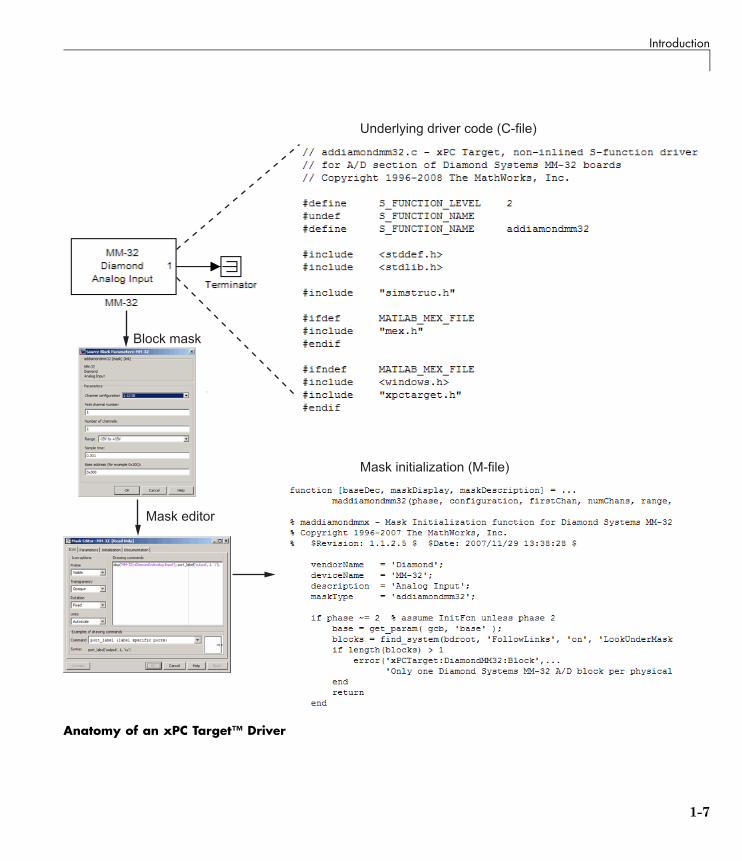
What Makes Up an xPC Target Driver?An xPC Target device driver is an S-function with functions that access anI/O board.
Like any device driver, an xPC Target driver interfaces between the user andan I/O device. Unlike typical device drivers, xPC Target device drivers:
• Can have the following parts
- Driver code, that is C code written as an S-function using exported xPCTarget kernel functions (see “xPC Target Exported Functions” on page1-6)
- Optional Simulink block interface (Simulink mask) that users use toconfigure the device and access output
- Optional MATLAB code that you can write to perform operations such ascross-block checking or parameter value range checking. You referencethis file through the Simulink mask.
• Can be included in a Simulink library
• Are configured like any other Simulink block
1-6
Introduction
��������
�� �������� �������� ����������
���� ����
������������������������
Anatomy of an xPC Target™ Driver
1-7
1 Customizing xPC Target™ Drivers
Before You Start
In this section...
“Introduction” on page 1-8
“Driver Types” on page 1-9
“Bus Types and Register Access” on page 1-9
“Register Access” on page 1-10
“Inlining xPC Target Drivers” on page 1-10
IntroductionThis topic assumes that you satisfy the requirements outlined earlier in“Expected Background” on page 1-3 and that you have reviewed the followingsections to prepare:
• “References” on page 1-4
• “Source Code” on page 1-5
• “xPC Target Exported Functions” on page 1-6
• “Third-Party Directory” on page 1-6
It also assumes that you already have a board for which you want to writea driver. Before you start, use the following checklist to specify the driveryou want to write:
• Determine the functions of your board that you want to access with yourdriver.
• Determine the bus type for the board.
- PCI
- ISA
• Select the I/O access mapping type.
- I/O port mapped
- Memory address mapped
1-8
Before You Start
• Select polling versus interrupt.
• Specify the blocks for the drivers. Identify
- Input and output ports
- Mask parameters
- Work variables to be shared between driver start, output, and terminateroutines
• Determine your timing considerations.
• Decide whether you use Inlined functions.
If yes, see the Target Language Compiler documentation of the Real-TimeWorkshop.
Driver Types
• Standard I/O
• Communication
• DMA
• Interrupt-driven
Bus Types and Register AccessThe xPC Target software supports the two standard PC bus types, ISA andPCI. The ISA bus is a 16-bit bus with an 8 MHz clock. Another form of ISAbus is the PC/104. The PCI bus is a 32-bit or 64-bit bus with a 33 MHz or 66MHz clock. Another form of PCI bus is the PC/104+ (PC/104-Plus).
A driver performs I/O accesses through either I/O ports or memory addresses(memory mapped).
The xPC Target software accesses I/O port addresses for ISA and PCI busesas follows:
1-9
1 Customizing xPC Target™ Drivers
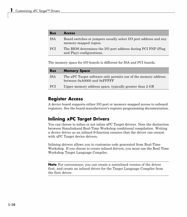
Bus Access
ISA Board switches or jumpers usually select I/O port address and anymemory-mapped region.
PCI The BIOS determines the I/O port address during PCI PNP (Plugand Play) configurations.
The memory space for I/O boards is different for ISA and PCI boards.
Bus Memory Space
ISA The xPC Target software only permits use of the memory addressbetween 0xA0000 and 0xFFFFF
PCI Upper memory address space, typically greater than 2 GB
Register AccessA device board supports either I/O port or memory-mapped access to onboardregisters. See the board manufacturer’s register programming documentation.
Inlining xPC Target DriversYou can choose to inline or not inline xPC Target drivers. Note the distinctionbetween Simulinkand Real-Time Workshop conditional compilation. Writinga device driver as an inlined S-function ensures that the driver can coexistwith xPC Target device drivers.
Inlining drivers allows you to customize code generated from Real-TimeWorkshop. If you choose to create inlined drivers, you must use the Real-TimeWorkshop Target Language Compiler.
Note For convenience, you can create a noninlined version of the driverfirst, and create an inlined driver for the Target Language Compiler fromthe first driver.
1-10
Creating a Custom Driver
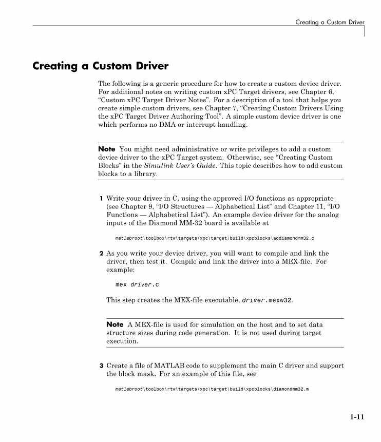
Creating a Custom DriverThe following is a generic procedure for how to create a custom device driver.For additional notes on writing custom xPC Target drivers, see Chapter 6,“Custom xPC Target Driver Notes”. For a description of a tool that helps youcreate simple custom drivers, see Chapter 7, “Creating Custom Drivers Usingthe xPC Target Driver Authoring Tool”. A simple custom device driver is onewhich performs no DMA or interrupt handling.
Note You might need administrative or write privileges to add a customdevice driver to the xPC Target system. Otherwise, see “Creating CustomBlocks” in the Simulink User’s Guide. This topic describes how to add customblocks to a library.
1 Write your driver in C, using the approved I/O functions as appropriate(see Chapter 9, “I/O Structures — Alphabetical List” and Chapter 11, “I/OFunctions — Alphabetical List”). An example device driver for the analoginputs of the Diamond MM-32 board is available at
matlabroot\toolbox\rtw\targets\xpc\target\build\xpcblocks\addiamondmm32.c
2 As you write your device driver, you will want to compile and link thedriver, then test it. Compile and link the driver into a MEX-file. Forexample:
mex driver.c
This step creates the MEX-file executable, driver.mexw32.
Note A MEX-file is used for simulation on the host and to set datastructure sizes during code generation. It is not used during targetexecution.
3 Create a file of MATLAB code to supplement the main C driver and supportthe block mask. For an example of this file, see
matlabroot\toolbox\rtw\targets\xpc\target\build\xpcblocks\diamondmm32.m
1-11
1 Customizing xPC Target™ Drivers
4 Open the Simulink Library Browser and create a new library, for example,your_company_namelib.mdl (see “Creating Block Libraries” in the“Working with Block Libraries” in the chapter of Simulink User’s Guide).Use a unique library name to prevent conflicts with other libraries.
5 In the new library, create an S-function block. From the Simulink LibraryBrowser, drag an S-Function block to the new library.
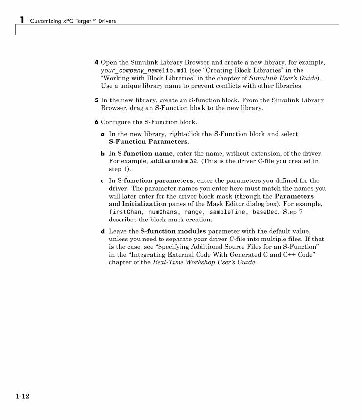
6 Configure the S-Function block.
a In the new library, right-click the S-Function block and selectS-Function Parameters.
b In S-function name, enter the name, without extension, of the driver.For example, addiamondmm32. (This is the driver C-file you created instep 1).
c In S-function parameters, enter the parameters you defined for thedriver. The parameter names you enter here must match the names youwill later enter for the driver block mask (through the Parametersand Initialization panes of the Mask Editor dialog box). For example,firstChan, numChans, range, sampleTime, baseDec. Step 7describes the block mask creation.
d Leave the S-function modules parameter with the default value,unless you need to separate your driver C-file into multiple files. If thatis the case, see “Specifying Additional Source Files for an S-Function”in the “Integrating External Code With Generated C and C++ Code”chapter of the Real-Time Workshop User’s Guide.
1-12
Creating a Custom Driver
7 Double-click the S-Function block and create a block mask (see Chapter 4,“Masking Drivers”).
8 Save and close the S-Function block.
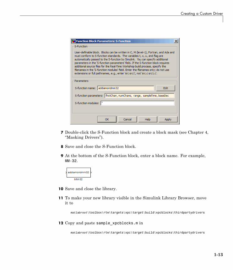
9 At the bottom of the S-Function block, enter a block name. For example,MM-32.
10 Save and close the library.
11 To make your new library visible in the Simulink Library Browser, moveit to
matlabroot\toolbox\rtw\targets\xpc\target\build\xpcblocks\thirdpartydrivers
12 Copy and paste sample_xpcblocks.m in
matlabroot\toolbox\rtw\targets\xpc\target\build\xpcblocks\thirdpartydrivers
1-13
1 Customizing xPC Target™ Drivers
Rename this file your_company_namelib_xpcblocks.m and edit this file asfollows:
• Set out.Library to your new library.
out.Library = 'your_company_namelib';
• Set out.Name to a string, such as the library name.
out.Name = 'your_company_namelib Blockset';
This string will appear in the Simulink Library Browser.
• Ensure that out.IsFlat is set to 0.
out.IsFlat = 0;
Note Ensure that you create a function that calls the out structure.
13 (Optional for PCI boards) To enable the getxpcpci function to account foryour new board, copy sample_supported.m to a unique file name. Forexample:
your_company_namelib_supported.m
Edit your copy of the file. For each board for which you add a device driver:
a Copy one of the commented structures in the file.
b Remove the comment symbols (%).
c Starting with 1, change the ID number as necessary. Number the devicestructures sequentially, starting with 1.
d Replace the field entries with your equivalents.
A structure entry might look like:
boards(1).VendorID = '18f7';boards(1).DeviceID = '0004';boards(1).SubVendorID = '-1';boards(1).SubDeviceID = '-1';boards(1).DeviceName = '422/2-PCI-335';
1-14
Creating a Custom Driver
boards(1).VendorName = 'Commtech';boards(1).DeviceType = 'Serial Ports';
e Save and close the file.
f To confirm your entries, type getxpcpci('all') in the MATLABCommand Window.
14 Ensure that all your driver files, including include files, are in the directory:
matlabroot\toolbox\rtw\targets\xpc\target\build\xpcblocks\thirdpartydrivers
Ensure that these files have unique names to prevent conflicts.
15 To update the directories that you added, at the MATLAB CommandWindow, type
rehash toolbox
When you are done, your library will appear in the Simulink Library Browserwith xPC Target: added to the beginning of the library name.
xPC Target: your_company_namelib Blockset
1-15
1 Customizing xPC Target™ Drivers
Debugging NotesWhile developing your custom driver, you can use printf statements in yourcode. This displays output on the left-hand side of the target PC monitor. Ifyour printf statements scroll off the monitor, consider disabling the targetPC scope area to provide more display area for these statements:
1 At the MATLAB Command Window, type xpcexplr to start xPC TargetExplorer.
2 In xPC Target Explorer, navigate to target_PC_node >Configuration > Appearance.
3 Clear the Enable target scope check box.
4 Recreate the target boot disk and reboot the target PC.
The scope area on the target PC monitor no longer appears.
5 Continue with the device driver development.
1-16
2
PCI Drivers
• “PCI Bus Considerations” on page 2-2
• “Sample PCI Device Driver” on page 2-8
2 PCI Drivers
PCI Bus Considerations
In this section...
“Introduction” on page 2-2
“PCI Configuration Space API” on page 2-3
“Memory-Mapped Accesses” on page 2-6
“I/O Port Accesses” on page 2-6
IntroductionWhen writing xPC Target drivers for PCI devices, consider the memory accessmethod. A PCI device can be either I/O port mapped or memory mapped.
• I/O port mapped — The BIOS assigns a port range.
• Memory mapped — The BIOS assigns a memory region, if your deviceis memory mapped.
The PC BIOS automatically assigns a conflict-free set of resources to any PCIdevice found in the system at boot-up. You typically do not know where theboard resides (base address) before driver initialization. However, you canobtain this information by querying the PCI configuration space at run time.The xPC Target software provides functions to accomplish this (see the “PCIConfiguration Information” on page 10-2 functions).
To locate a PCI device, you need the following:
• Vendor and device ID
• Optionally, subsystem vendor and subsystem device ID
Note You need the subsystem vendor and subsystem device ID if thevendor and device ID do not uniquely identify the board.
• Slot number or bus and slot number
2-2
PCI Bus Considerations
You can have the drivers locate PCI devices in one of the following ways:
• If the system has one board of any one type, you can use the driver slotoption to search for the first board that matches a vendor and device ID. Toinitiate this search, set this option to -1.
• If the system contains multiple boards of the same type, setting the slotoption to -1 does not find the additional boards. In that case, specify thebus and slot numbers with the vendor and device IDs.
PCI Configuration Space APIBefore you can access a PCI device, you need to access the configuration spaceto locate the board in the target PC memory. This section describes theprocedure to do this.
For PCI devices, the driver will need to access the PCI configuration spacefor the board. This space contains relevant board information such as thebase address and access type (I/O port or memory mapped). The xPC Targetsoftware provides functions that allow the driver to access this space.
• Vendor and device ID — The driver searches all boards for the specifiedvendor (manufacturer) and device ID. The PCI Steering Committee, anindependent standards body, assigns a unique vendor ID (uint16) to eachPCI board vendor. Each vendor then assigns a unique ID to each PCI boardtype it supports.
Note Vendor and device IDs do not always uniquely identify a board. Forexample, all boards that use the PLX-9080 bus interface chip have a vendorID of 10B5 (the vendor ID assigned to PLX Technology, Inc.). The deviceID for the chip is 9080. In cases like this, to select a particular board thatcontains this chip, you must use a subvendor and subdevice ID in additionto the vendor and device IDs.
• Slot number or bus and slot number — The driver looks only for the boardthat matches the specified vendor and device ID and slot number.
2-3
2 PCI Drivers
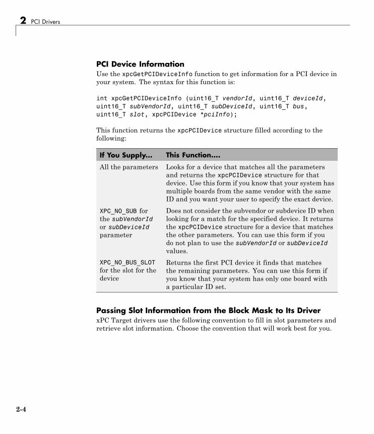
PCI Device InformationUse the xpcGetPCIDeviceInfo function to get information for a PCI device inyour system. The syntax for this function is:
int xpcGetPCIDeviceInfo (uint16_T vendorId, uint16_T deviceId,uint16_T subVendorId, uint16_T subDeviceId, uint16_T bus,uint16_T slot, xpcPCIDevice *pciInfo);
This function returns the xpcPCIDevice structure filled according to thefollowing:
If You Supply... This Function....
All the parameters Looks for a device that matches all the parametersand returns the xpcPCIDevice structure for thatdevice. Use this form if you know that your system hasmultiple boards from the same vendor with the sameID and you want your user to specify the exact device.
XPC_NO_SUB forthe subVendorIdor subDeviceIdparameter
Does not consider the subvendor or subdevice ID whenlooking for a match for the specified device. It returnsthe xpcPCIDevice structure for a device that matchesthe other parameters. You can use this form if youdo not plan to use the subVendorId or subDeviceIdvalues.
XPC_NO_BUS_SLOTfor the slot for thedevice
Returns the first PCI device it finds that matchesthe remaining parameters. You can use this form ifyou know that your system has only one board witha particular ID set.
Passing Slot Information from the Block Mask to Its DriverxPC Target drivers use the following convention to fill in slot parameters andretrieve slot information. Choose the convention that will work best for you.
2-4
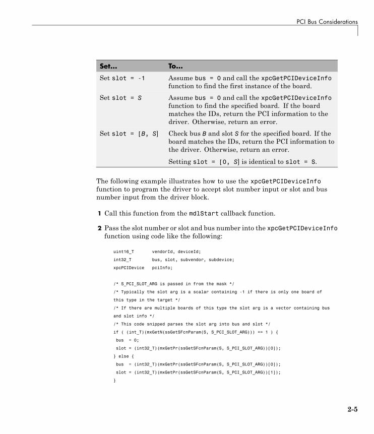
PCI Bus Considerations
Set... To...
Set slot = -1 Assume bus = 0 and call the xpcGetPCIDeviceInfofunction to find the first instance of the board.
Set slot = S Assume bus = 0 and call the xpcGetPCIDeviceInfofunction to find the specified board. If the boardmatches the IDs, return the PCI information to thedriver. Otherwise, return an error.
Set slot = [B, S] Check bus B and slot S for the specified board. If theboard matches the IDs, return the PCI information tothe driver. Otherwise, return an error.
Setting slot = [0, S] is identical to slot = S.
The following example illustrates how to use the xpcGetPCIDeviceInfofunction to program the driver to accept slot number input or slot and busnumber input from the driver block.
1 Call this function from the mdlStart callback function.
2 Pass the slot number or slot and bus number into the xpcGetPCIDeviceInfofunction using code like the following:
uint16_T vendorId, deviceId;
int32_T bus, slot, subvendor, subdevice;
xpcPCIDevice pciInfo;
/* S_PCI_SLOT_ARG is passed in from the mask */
/* Typically the slot arg is a scalar containing -1 if there is only one board of
this type in the target */
/* If there are multiple boards of this type the slot arg is a vector containing bus
and slot info */
/* This code snipped parses the slot arg into bus and slot */
if ( (int_T)(mxGetN(ssGetSFcnParam(S, S_PCI_SLOT_ARG))) == 1 ) {
bus = 0;
slot = (int32_T)(mxGetPr(ssGetSFcnParam(S, S_PCI_SLOT_ARG))[0]);
} else {
bus = (int32_T)(mxGetPr(ssGetSFcnParam(S, S_PCI_SLOT_ARG))[0]);
slot = (int32_T)(mxGetPr(ssGetSFcnParam(S, S_PCI_SLOT_ARG))[1]);
}
2-5
2 PCI Drivers
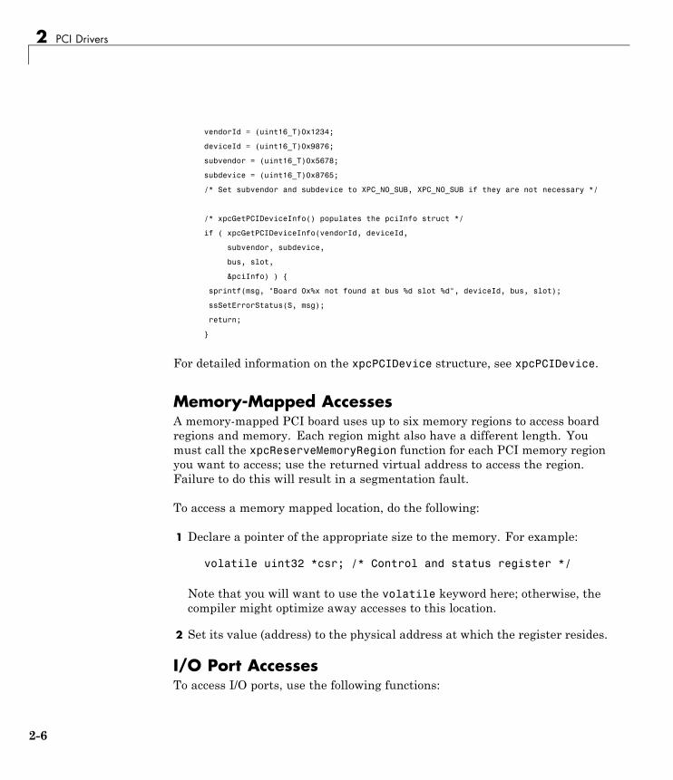
vendorId = (uint16_T)0x1234;
deviceId = (uint16_T)0x9876;
subvendor = (uint16_T)0x5678;
subdevice = (uint16_T)0x8765;
/* Set subvendor and subdevice to XPC_NO_SUB, XPC_NO_SUB if they are not necessary */
/* xpcGetPCIDeviceInfo() populates the pciInfo struct */
if ( xpcGetPCIDeviceInfo(vendorId, deviceId,
subvendor, subdevice,
bus, slot,
&pciInfo) ) {
sprintf(msg, "Board 0x%x not found at bus %d slot %d", deviceId, bus, slot);
ssSetErrorStatus(S, msg);
return;
}
For detailed information on the xpcPCIDevice structure, see xpcPCIDevice.
Memory-Mapped AccessesA memory-mapped PCI board uses up to six memory regions to access boardregions and memory. Each region might also have a different length. Youmust call the xpcReserveMemoryRegion function for each PCI memory regionyou want to access; use the returned virtual address to access the region.Failure to do this will result in a segmentation fault.
To access a memory mapped location, do the following:
1 Declare a pointer of the appropriate size to the memory. For example:
volatile uint32 *csr; /* Control and status register */
Note that you will want to use the volatile keyword here; otherwise, thecompiler might optimize away accesses to this location.
2 Set its value (address) to the physical address at which the register resides.
I/O Port AccessesTo access I/O ports, use the following functions:
2-6
PCI Bus Considerations
• xpcInpB, xpcInpW, xpcInpDW— I/O port input functions for byte, word,and double word accesses
• xpcOutpB, xpcOutpW, xpcOutpDW — I/O port output functions for byte,word, and double word accesses
2-7
2 PCI Drivers
Sample PCI Device DriverFor example PCI device driver code, see
matlabroot\toolbox\rtw\targets\xpc\target\build\xpcblocks\dikpc
i1800.c
This driver illustrates digital input driver code for the Keithley 1800 seriesPCI devices.
Note Remember to enter the C-file name (without the extension) as theS-function name for the S-Function block.
2-8
3
ISA and PC/104 Drivers
3 ISA and PC/104 Drivers
ISA and PC/104 Bus Considerations
In this section...
“Introduction” on page 3-2
“I/O Mapped” on page 3-2
“Memory Mapped” on page 3-3
IntroductionWhen writingxPC Target drivers for ISA and PC/104 devices, consider thememory access method. A PCI device can be either port mapped or memorymapped. Most ISA and PC/104 boards are port mapped. Those that arememory mapped typically need large register banks or are interfaced viadual-port memory.
Note ThexPC Target kernel does not support ISA and PC/104 PNP boards.This means that you can write xPC Target device drivers only for ISA andPC/104 boards for which you can set the base address manually. To manuallyset the base address, insert jumpers or move DIP switches on the board.
• Port mapped
The base port address on the board is set via jumpers or switches. Youmight need to reset these addresses if there are conflicts.
• Memory mapped
The I/O and memory on the board are set via jumpers or switches. Youmight need to reset these addresses if there are conflicts.
I/O MappedThe base port address on the board is set via jumpers or switches. Driverscannot discover these addresses on their own; you must specify theseaddresses to the driver.
3-2

ISA and PC/104 Bus Considerations
Memory MappedThe I/O and memory on the board is set via jumpers or switches. Driverscannot discover these addresses on their own; you must specify theseaddresses to the driver.
Reserved Space on the Target PCThe xPC Target kernel reserves space in the region (C0000 to DC000) formemory-mapped I/O cards. You must set up ISA and PC/104 cards to useaddresses in this range.
3-3

3 ISA and PC/104 Drivers
3-4

4
Masking Drivers
• “Creating Driver Subsystem Masks” on page 4-2
• “Driver Mask Guidelines” on page 4-3
• “Cross-Block Checking” on page 4-5
• “When You Are Done” on page 4-6
• “Sample Driver Mask” on page 4-7
4 Masking Drivers
Creating Driver Subsystem MasksThis chapter describes guidelines for creating a Simulink block user interface(mask) for the S-Function block associated your driver. A mask definesthe menu items that will be passed to the S-function. The mask can call aMATLAB file to do parameter or range value checking. You can also modifythe labels of a block to show port numbers or other information. After youcreate the C code for an xPC Target device driver:
1 Create an optional MATLAB file.
2 Create an S-Function block for the driver.
3 Create a mask for the S-Function block.
This is the basic Simulink mask, with parameters and descriptions asnecessary. When you are done, you can make the device driver and itsmask available for users to add to their models.
4-2
Driver Mask Guidelines
Driver Mask GuidelinesThis topic lists guidelines you should follow when creating a mask for yourxPC Target driver. You should already know how to create masked blocks.See the “Working with Block Masks” chapter in Simulink User’s Guide forfurther information.
Users access the masked block to interact with the driver, which in turninteracts with the device.
• Create an S-Function block for the driver.
• Decide on the set of parameters the user will need to provide to the driver.You should have already programmed this into the driver C code itself.
• Select appropriate descriptive names for these parameters.
• For each parameter, decide if the parameter can accept a finite number ofpossible input values. If yes, consider using one of the following widgets:
- Check box — For yes/no or 1/0 inputs
- Drop-down list — For a finite list of choices
Your mask can also be dynamic, where the dialog changes according touser selections.
• Choose readable and appropriate variable names.
• As necessary and appropriate, configure the library block so that the blockmask modifies its label according to user input. For example, a check boxmight cause the dialog to change.
• Ensure that the title beneath the driver block terminates with a blankspace. This is because if a model contains more than one block of any giventype, Simulink appends a number to the title under the block. Adding ablank space to the end of the label ensures readability.
• Name the block appropriately so that it indicates the purpose of the driver.
• If you want to link help information to the mask Help button, see in the“Working with Block Masks” chapter of Simulink User’s Guide for details.
• From within the mask, you can call a custom file to perform a number ofoperations, including the following:
4-3
4 Masking Drivers
- Range checking for all parameters. For example, if you expect inputvalues from 1 to 10, do not allow users to enter negative values, orvalues greater than 10.
- Cross-block checking (see “Cross-Block Checking” on page 4-5).
4-4
Cross-Block Checking
Cross-Block CheckingCross-block checking determines if multiple blocks are trying to access thesame hardware. You should include cross-block checking in your driverto prevent such conflicts. You can perform cross-block checking by callingfind_system from the block mask in a number of ways. Use the followingguidelines when performing cross-block checking:
• The recommended way is to call the find_system function from the blockInitFcn callback function. There are two phases of MATLAB file executionduring an update system operation. If you call the find_system functionfrom a block InitFcn callback function, defined in the Block Parametersdialog of the block, no additional updates are triggered.
• Decide on the level of cross-block checking for your hardware. For example,boards that use the 8255 chip for digital I/O need to check if two differentblocks are requesting opposing directions (for example, input and output)for the same group of 8 bits. On this chip, there are three groups of 8 bits.You can configure each group for input or output. The associated xPCTarget driver generates an error in InitFcn if find_system detects thattwo blocks are trying to use the same group of 8 bits for input and output.See
matlabroot\toolbox\rtw\targets\xpc\target\build\xpcblocks\mpci8255.m
which is called as mpci8255(1) for the Measurement Computing PCI-DAS1200 digital input and output blocks. During an update diagram sequence,Simulink calls the InitFcn callback function once for each block. Simulinkmight call the initialization commands in the mask multiple times.
4-5
4 Masking Drivers
When You Are DoneAfter you write the driver S-function and create the S-Function block, optionalblock mask, and MATLAB file for it, be sure to:
• Check the text of each error message for spelling and appropriateness.
• (Optional) Use a coding standard indentation such as four or eight spaceswith no tabs.
• Copy your new blocks into a custom directory with a unique name.
To enable your new blocks to be viewable in the Simulink Library Browser,see “Creating a Custom Driver” on page 1-11.
• Test the driver for the following:
- Run the mex command on the driver to build the driver for simulationand code generation.
- Verify the hardware I/O under as many conditions as possible.
4-6
Sample Driver Mask
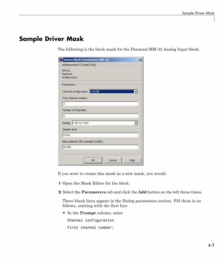
Sample Driver MaskThe following is the block mask for the Diamond MM-32 Analog Input block.
If you were to create this mask as a new mask, you would:
1 Open the Mask Editor for the block.
2 Select the Parameters tab and click the Add button on the left three times.
Three blank lines appear in the Dialog parameters section. Fill them in asfollows, starting with the first line:
• In the Prompt column, enter
Channel configuration
First channel number:
4-7
4 Masking Drivers
Number of channels:
Range
Sample time:
Base address (for example 0x300):
• In the Variable column, enter the parameter names. Be sure that thesenames match the S-function parameters field of the S-Function block.
configuration
firstChan
numChans
range
sampleTime
base
• In the Type column, select:
popup
edit
edit
popup
edit
edit
• In the Evaluate and Tunable columns, ensure that the first five checkboxes of Evaluate and all the check boxes for Tunable are selected.
4-8
Sample Driver Mask
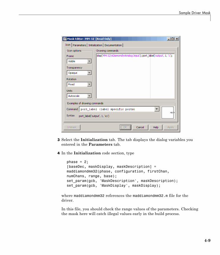
3 Select the Initialization tab. The tab displays the dialog variables youentered in the Parameters tab.
4 In the Initialization code section, type
phase = 2;[baseDec, maskDisplay, maskDescription] =maddiamondmm32(phase, configuration, firstChan,numChans, range, base);set_param(gcb, 'MaskDescription', maskDescription);set_param(gcb, 'MaskDisplay', maskDisplay);
where maddiamondmm32 references the maddiamondmm32.m file for thedriver.
In this file, you should check the range values of the parameters. Checkingthe mask here will catch illegal values early in the build process.
4-9
4 Masking Drivers
This example returns a string to display on the block with the variableport_label commands with which to label the input and output ports. Thenumber and content of the port_label commands depend on the channelvector that the user enters in the mask.
5 Select the Documentation tab. This tab contains three fields,Mask type,Mask description, and Mask help.
In the Mask type field, enter the type of driver. For example:
addiamondmm32
In the Mask description field, enter a description for the driver. Forexample:
MM-32DiamondAnalog Input
In the Mask help field, if you are providing any online documentation toassociate with the Help button, you can call that online documentationfrom this field. See in the “Working with Block Masks” chapter of SimulinkUser’s Guide for details.
6 Click OK to save the mask.
After you create the block mask, you can define an InitFcn callback for theblock. A model calls this callback at the start of model simulation.
1 Right-click the block and select Block Properties from the drop-down list.
2 Select the Callback tab from the dialog. From the list, select InitFcn.Enter MATLAB code in the edit box.
One convention is to use the same function that is used at maskinitialization time (for example, maddiamondmm32.m), but with a singleargument that indicates that this is being called at InitFcn time.
maddiamondmm32(1)
4-10
Sample Driver Mask
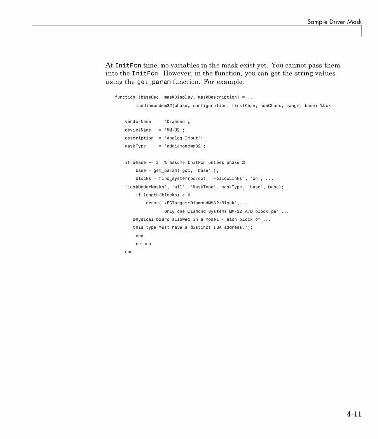
At InitFcn time, no variables in the mask exist yet. You cannot pass theminto the InitFcn. However, in the function, you can get the string valuesusing the get_param function. For example:
function [baseDec, maskDisplay, maskDescription] = ...
maddiamondmm32(phase, configuration, firstChan, numChans, range, base) %#ok
vendorName = 'Diamond';
deviceName = 'MM-32';
description = 'Analog Input';
maskType = 'addiamondmm32';
if phase ~= 2 % assume InitFcn unless phase 2
base = get_param( gcb, 'base' );
blocks = find_system(bdroot, 'FollowLinks', 'on', ...
'LookUnderMasks', 'all', 'MaskType', maskType, 'base', base);
if length(blocks) > 1
error('xPCTarget:DiamondMM32:Block',...
'Only one Diamond Systems MM-32 A/D block per ...
physical board allowed in a model - each block of ...
this type must have a distinct ISA address.');
end
return
end
4-11

4 Masking Drivers
4-12

5
Interrupt Support
• “xPC Target Interrupts” on page 5-2
• “Adding Interrupt Support” on page 5-7
• “Hook Function Prototypes — Alphabetical List” on page 5-15
5 Interrupt Support
xPC Target Interrupts
In this section...
“Introduction” on page 5-2
“Interrupt Processing in the xPC Target Environment” on page 5-2
IntroductionIf your device supports interrupts, you can use the procedures in this chapterto add your custom interrupt functions to the xPC Target framework.
Your users can use interrupts in xPC Target applications in one of thefollowing ways:
• Use the interrupt with the xPC Target Async IRQ Source block to execute afunction-call subsystem when an interrupt occurs.
• Use the interrupt to run the model in place of the timer interrupt, availablethrough the model Configuration Parameters dialog box in the Real-TimeWorkshop > xPC Target options pane.
Note Although users can use interrupts in one of two ways, you program forthese interrupts using the same procedure, as described in “Adding InterruptSupport” on page 5-7. However, before you start programming the interrupts,see “Interrupt Processing in the xPC Target Environment” on page 5-2 for adescription of the flow of xPC Target interrupt processing.
Interrupt Processing in the xPC Target EnvironmentWhen a model executes, it executes in the following order:
1 Call all mdlStart routines in block execution order.
2 Call the Start function, if one exists.
3 Allow background graphics and network tasks to run until an interruptoccurs.
5-2
xPC Target™ Interrupts
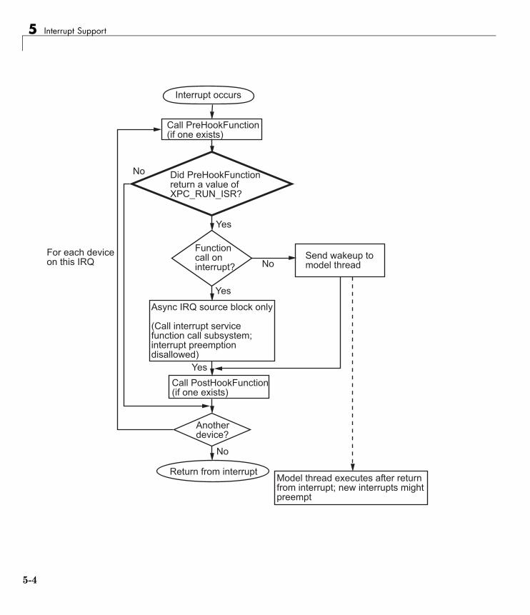
The following illustrates the flow of processing once a hardware interruptoccurs. This is background information to help you understand the context inwhich the interrupt functions run.
5-3
5 Interrupt Support
���������������
������� ���!����������������"���
#� ���� ���!����������������������$��%&�'%�(&)
!����������������������)
(�� �*��������� ����+��
������� ���!����������������"���
,���+�� �����)
&��������������������
!�����+� ���������+���&-
,�����&-�������.���������
�����������������������������������.����/�������������������� ����*� �
'�
0�
'�
0�
'�
0�
�� ����+�� ��"�������������������������������/���*��������������+��������
5-4
xPC Target™ Interrupts
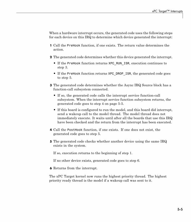
When a hardware interrupt occurs, the generated code uses the following stepsfor each device on this IRQ to determine which device generated the interrupt:
1 Call the PreHook function, if one exists. The return value determines theaction.
2 The generated code determines whether this device generated the interrupt.
• If the PreHook function returns XPC_RUN_ISR, execution continues tostep 3.
• If the PreHook function returns XPC_DROP_ISR, the generated code goesto step 5.
3 The generated code determines whether the Async IRQ Source block has afunction-call subsystem connected.
• If so, the generated code calls the interrupt service function-callsubsystem. When the interrupt service function subsystem returns, thegenerated code goes to step 4 on page 5-5.
• If this board is configured to run the model, and this board did interrupt,send a wakeup call to the model thread. The model thread does notimmediately execute. It waits until after all the boards that use this IRQhave been checked and the return from the interrupt has been executed.
4 Call the PostHook function, if one exists. If one does not exist, thegenerated code goes to step 5.
5 The generated code checks whether another device using the same IRQexists in the system.
If so, execution returns to the beginning of step 1.
If no other device exists, generated code goes to step 6.
6 Returns from the interrupt.
The xPC Target kernel now runs the highest priority thread. The highestpriority ready thread is the model if a wakeup call was sent to it.
5-5
5 Interrupt Support
Note The Allow preemption of function call subsystem check box hasno effect. Interrupts are never enabled when the function-call subsystemis executed.
5-6
Adding Interrupt Support
Adding Interrupt Support
In this section...
“Introduction” on page 5-7
“Guidelines for Creating Interrupt Functions” on page 5-9
“Filling in the Driver board Structure” on page 5-10
IntroductionTo add interrupt handling for a custom driver, you must create
• A descriptor file to connect a board type to the functions needed to start,handle, and stop interrupts
• A C file to implement these functions
Include the following functions. See “Hook Function Prototypes —Alphabetical List” on page 5-15 for the prototype details.
Function Description
PreHook Runs just before either a function-call subsystemor entire model is called. Program this function toacknowledge the interrupt and cause the board tostop issuing the interrupt signal.
PostHook Runs after return from function call on interrupt,and before model execution. It is typically not used.
5-7
5 Interrupt Support
Function Description
Start Runs as the last item when starting a model, justbefore the model runs. It is typically used to turnon interrupt generation. Program this function toenable interrupts on the board and start any action.
Stop Runs at the beginning of a stop request, before anymdlTerminate entries for any block in the modelruns. It is typically used to turn off interruptgeneration. Program this function to disableinterrupts from the board and stop any action. Thisis the first action called, when a target applicationstops executing.
Note You must use the Stop function to turn off interrupts if you have turnedthem on in the Start function. In this way, the stop and start functionsshould cancel each other.
To add interrupts for your custom driver, use the following general steps:
1 Create a hook file in the following directory:
matlabroot\toolbox\rtw\targets\xpc\target\build\xpcblocks\thirdpartydrivers
Hook files are C files (.c). For example, look at files inmatlabroot\toolbox\rtw\targets\xpc\target\build\src, such asxpc6804hooks.c.
2 Name the hook file something like:
your_company_name_board_hook.c
3 As necessary, create the interrupt functions the PreHook, PostHook, Start,and Stop functions and add them to the hook file. See “Guidelines forCreating Interrupt Functions” on page 5-9 for information on how to createthese functions.
5-8
Adding Interrupt Support
4 Copy the file sample_int.m to a unique file name in the following directory:
matlabroot\toolbox\rtw\targets\xpc\target\build\xpcblocks\thirdpartydrivers
For example:
your_company_name_int.m
The xPC Target software searches in this directory for file names that endwith _int.m and looks for board interrupt descriptions.
5 Open and edit the following file:
matlabroot\toolbox\rtw\targets\xpc\target\build\xpcblocks\thirdpartydrivers\your_company_name_int.m
Add to this file a board structure for each xPC Target supported board forwhich interrupt functions have been written. See “Filling in the Driverboard Structure” on page 5-10 for a description of how to fill in a boardstructure.
6 Save and close the file.
7 At the MATLAB Command Window, type:
rehash toolbox
8 Restart the MATLAB interface to update the Async IRQ Source block andConfiguration Parameters dialogs.
Guidelines for Creating Interrupt FunctionsxPC Target interrupt functions have predefined purposes and typically followa particular order. This section describes the guidelines on creating interruptfunctions. See “Hook Function Prototypes — Alphabetical List” on page 5-15for the prototypes for these functions.
To prepare for the creation of the hook file, examine the existing xPC Targethook files (matlabroot\toolbox\rtw\targets\xpc\target\build\src) andcopy and modify one that is the same board type, PCI or ISA, as the board forwhich you are creating a custom driver. For example, xpc6804hooks.c is foran ISA board. Place your new file in
5-9
5 Interrupt Support
matlabroot\toolbox\rtw\targets\xpc\target\build\xpcblocks\thirdpartydrivers\
When modifying an existing hook file:
• Change the names of all of the functions to match those you have selectedfor your board.
• Do not change the function signatures.
• Do not remove the __cdecl string.
• The PreHook and PostHook functions run with interrupts disabled. Do notchange the interrupt status in these functions.
When writing the interrupt functions, note the following:
• When an interrupt occurs, the kernel calls the PreHook function.
Note This function is run with interrupts disabled. If this function cannotturn off the interrupt, an infinite loop will occur because the interruptservice routine (ISR) will continuously call the PreHook function.
• Because the PostHook function has limited use, you most likely do not needto define this function. Set this function to 'NULL' if you do not need it.
• The generated code calls the Start function during the startup phase ofmodel execution as the last action, after the model has called all mdlStartroutines.
This function is typically used to enable interrupts from the board. Thetarget application is ready to accept interrupts a few microseconds afterthis function is called. Do not try to enable interrupts from the boardmdlStart function.
• When a target application stops executing, the generated code calls theStop function first. Disable interrupts from the board in this function.
Filling in the Driver board StructureThis section describes how to fill in a driver board structure, element byelement.
5-10
Adding Interrupt Support
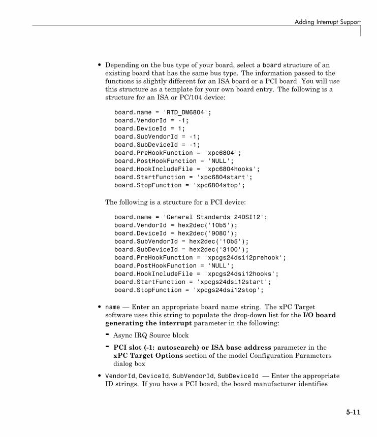
• Depending on the bus type of your board, select a board structure of anexisting board that has the same bus type. The information passed to thefunctions is slightly different for an ISA board or a PCI board. You will usethis structure as a template for your own board entry. The following is astructure for an ISA or PC/104 device:
board.name = 'RTD_DM6804';board.VendorId = -1;board.DeviceId = 1;board.SubVendorId = -1;board.SubDeviceId = -1;board.PreHookFunction = 'xpc6804';board.PostHookFunction = 'NULL';board.HookIncludeFile = 'xpc6804hooks';board.StartFunction = 'xpc6804start';board.StopFunction = 'xpc6804stop';
The following is a structure for a PCI device:
board.name = 'General Standards 24DSI12';board.VendorId = hex2dec('10b5');board.DeviceId = hex2dec('9080');board.SubVendorId = hex2dec('10b5');board.SubDeviceId = hex2dec('3100');board.PreHookFunction = 'xpcgs24dsi12prehook';board.PostHookFunction = 'NULL';board.HookIncludeFile = 'xpcgs24dsi12hooks';board.StartFunction = 'xpcgs24dsi12start';board.StopFunction = 'xpcgs24dsi12stop';
• name — Enter an appropriate board name string. The xPC Targetsoftware uses this string to populate the drop-down list for the I/O boardgenerating the interrupt parameter in the following:
- Async IRQ Source block
- PCI slot (-1: autosearch) or ISA base address parameter in thexPC Target Options section of the model Configuration Parametersdialog box
• VendorId, DeviceId, SubVendorId, SubDeviceId — Enter the appropriateID strings. If you have a PCI board, the board manufacturer identifies
5-11
5 Interrupt Support
that board with either two or four ID values, depending on the specifichardware. When calling the hook functions, the xPC Target kernel obtainsthe PCI information for the board and passes it to the hook functions. Usethese parameters to help identify the interrupting board.
- For VendorId and DeviceId, enter the IDs you get from the boardmanufacturer.
- Many boards do not have SubVendorId and SubDeviceId values. Inthese cases, insert the value -1 to prevent The xPC Target softwarefrom checking for them.
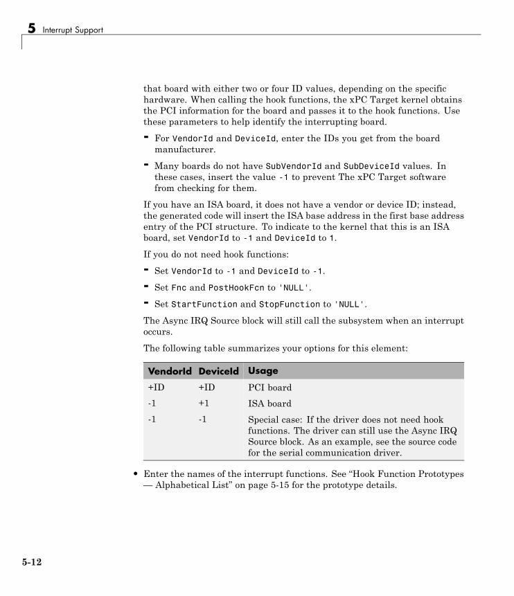
If you have an ISA board, it does not have a vendor or device ID; instead,the generated code will insert the ISA base address in the first base addressentry of the PCI structure. To indicate to the kernel that this is an ISAboard, set VendorId to -1 and DeviceId to 1.
If you do not need hook functions:
- Set VendorId to -1 and DeviceId to -1.
- Set Fnc and PostHookFcn to 'NULL'.
- Set StartFunction and StopFunction to 'NULL'.
The Async IRQ Source block will still call the subsystem when an interruptoccurs.
The following table summarizes your options for this element:
VendorId DeviceId Usage
+ID +ID PCI board
-1 +1 ISA board
-1 -1 Special case: If the driver does not need hookfunctions. The driver can still use the Async IRQSource block. As an example, see the source codefor the serial communication driver.
• Enter the names of the interrupt functions. See “Hook Function Prototypes— Alphabetical List” on page 5-15 for the prototype details.
5-12
Adding Interrupt Support
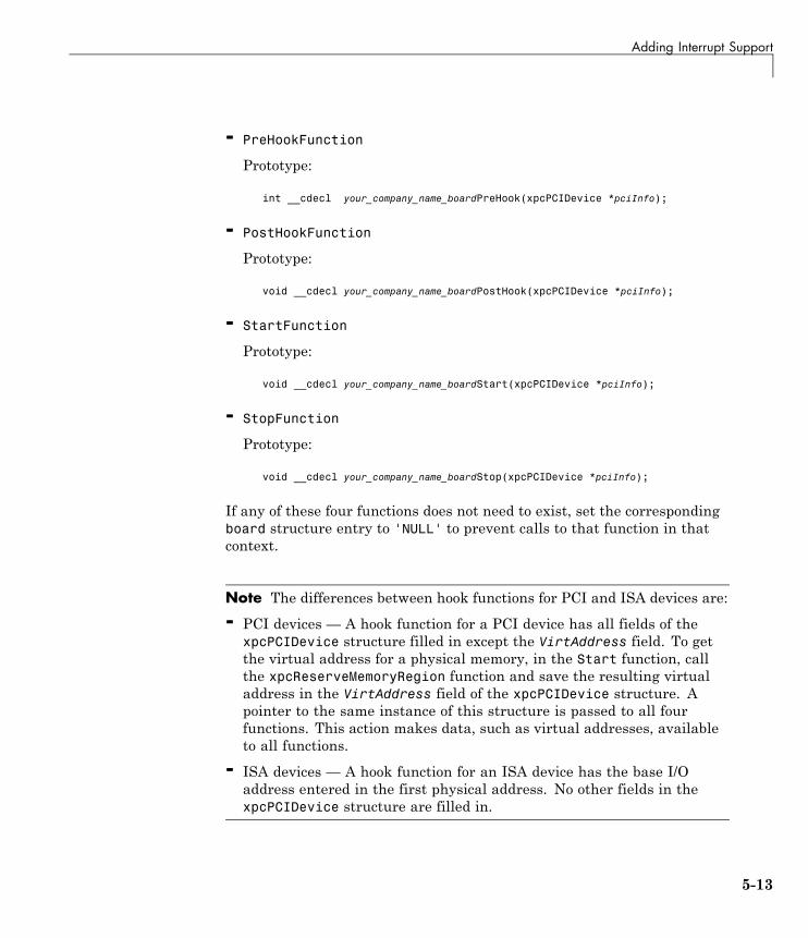
- PreHookFunction
Prototype:
int __cdecl your_company_name_boardPreHook(xpcPCIDevice *pciInfo);
- PostHookFunction
Prototype:
void __cdecl your_company_name_boardPostHook(xpcPCIDevice *pciInfo);
- StartFunction
Prototype:
void __cdecl your_company_name_boardStart(xpcPCIDevice *pciInfo);
- StopFunction
Prototype:
void __cdecl your_company_name_boardStop(xpcPCIDevice *pciInfo);
If any of these four functions does not need to exist, set the correspondingboard structure entry to 'NULL' to prevent calls to that function in thatcontext.
Note The differences between hook functions for PCI and ISA devices are:
- PCI devices — A hook function for a PCI device has all fields of thexpcPCIDevice structure filled in except the VirtAddress field. To getthe virtual address for a physical memory, in the Start function, callthe xpcReserveMemoryRegion function and save the resulting virtualaddress in the VirtAddress field of the xpcPCIDevice structure. Apointer to the same instance of this structure is passed to all fourfunctions. This action makes data, such as virtual addresses, availableto all functions.
- ISA devices — A hook function for an ISA device has the base I/Oaddress entered in the first physical address. No other fields in thexpcPCIDevice structure are filled in.
5-13
5 Interrupt Support
• HookIncludeFile — Interrupt handling file that contains thePreHookFunction, PostHookFunction, StartFunction, and StopFunctionfunctions for this board. Specify this name without the .c extension.
• Specify this structure for each board for which interrupt functions havebeen written. For example:
board(1).name = 'name1';...board(2).name = 'name2';
5-14
Hook Function Prototypes — Alphabetical List
Hook Function Prototypes — Alphabetical List• your_company_name_boardPostHook
• your_company_name_boardPreHook
• your_company_name_boardStart
• your_company_name_boardStop
5-15

your_company_name_boardPostHook
Purpose Run after return from interrupt service routine function-call subsystemor after sending wakeup call to model thread
Syntax void __cdecl your_company_name_boardPostHook(xpcPCIDevice*pciInfo);
Argument pciInfo Pointer to the PciDevice structure.
Description your_company_name_boardPostHook is not typically required. If youdo not need this function, set it to 'NULL' in
matlabroot\toolbox\rtw\targets\xpc\target\build\xpcblocks\thirdpartydrivers\your_company_name_int.m
See Also xpcPCIDevice
5-16
your_company_name_boardPreHook
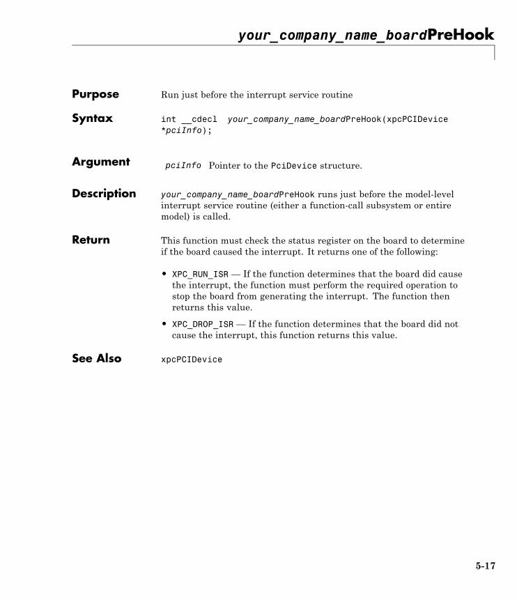
Purpose Run just before the interrupt service routine
Syntax int __cdecl your_company_name_boardPreHook(xpcPCIDevice*pciInfo);
Argument pciInfo Pointer to the PciDevice structure.
Description your_company_name_boardPreHook runs just before the model-levelinterrupt service routine (either a function-call subsystem or entiremodel) is called.
Return This function must check the status register on the board to determineif the board caused the interrupt. It returns one of the following:
• XPC_RUN_ISR— If the function determines that the board did causethe interrupt, the function must perform the required operation tostop the board from generating the interrupt. The function thenreturns this value.
• XPC_DROP_ISR — If the function determines that the board did notcause the interrupt, this function returns this value.
See Also xpcPCIDevice
5-17
your_company_name_boardStart
Purpose Run as the last item in mdlStart
Syntax void __cdecl your_company_name_boardStart(xpcPCIDevice*pciInfo);
Argument pciInfo Pointer to the PciDevice structure.
Description your_company_name_boardStart runs as the last item after allmdlStart functions. It is typically used to turn on interrupt generation.
See Also xpcPCIDevice
5-18
your_company_name_boardStop
Purpose Run at the beginning of mdlTerminate
Syntax void __cdecl your_company_name_boardStop(xpcPCIDevice*pciInfo);
Argument pciInfo Pointer to the PciDevice structure.
Description your_company_name_boardStop runs before the mdlTerminate functionof the blocks in the model. It is typically used to turn off interruptgeneration.
See Also xpcPCIDevice
5-19

your_company_name_boardStop
5-20
6
Custom xPC Target DriverNotes
• “S-Function Guidelines” on page 6-2
• “mdlStart and mdlTerminate Considerations” on page 6-4
• “DMA Considerations” on page 6-5
• “Passing Parameters” on page 6-6
• “Accessing Registers” on page 6-7
6 Custom xPC Target™ Driver Notes
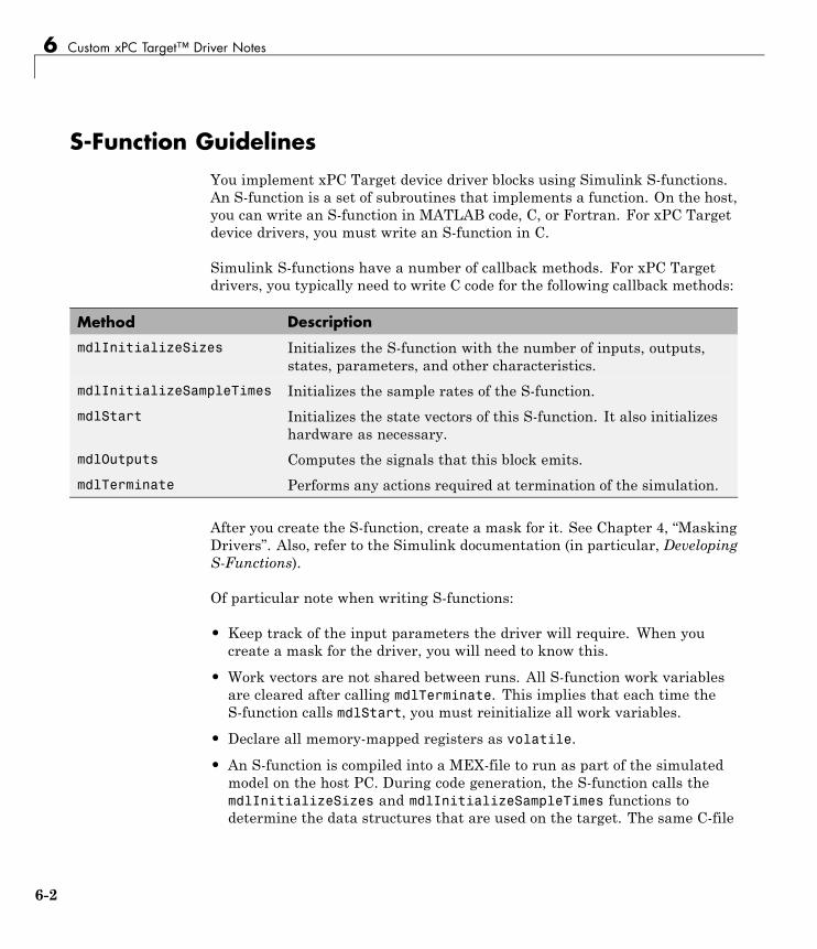
S-Function GuidelinesYou implement xPC Target device driver blocks using Simulink S-functions.An S-function is a set of subroutines that implements a function. On the host,you can write an S-function in MATLAB code, C, or Fortran. For xPC Targetdevice drivers, you must write an S-function in C.
Simulink S-functions have a number of callback methods. For xPC Targetdrivers, you typically need to write C code for the following callback methods:
Method Description
mdlInitializeSizes Initializes the S-function with the number of inputs, outputs,states, parameters, and other characteristics.
mdlInitializeSampleTimes Initializes the sample rates of the S-function.
mdlStart Initializes the state vectors of this S-function. It also initializeshardware as necessary.
mdlOutputs Computes the signals that this block emits.
mdlTerminate Performs any actions required at termination of the simulation.
After you create the S-function, create a mask for it. See Chapter 4, “MaskingDrivers”. Also, refer to the Simulink documentation (in particular, DevelopingS-Functions).
Of particular note when writing S-functions:
• Keep track of the input parameters the driver will require. When youcreate a mask for the driver, you will need to know this.
• Work vectors are not shared between runs. All S-function work variablesare cleared after calling mdlTerminate. This implies that each time theS-function calls mdlStart, you must reinitialize all work variables.
• Declare all memory-mapped registers as volatile.
• An S-function is compiled into a MEX-file to run as part of the simulatedmodel on the host PC. During code generation, the S-function calls themdlInitializeSizes and mdlInitializeSampleTimes functions todetermine the data structures that are used on the target. The same C-file
6-2
S-Function Guidelines
is also compiled with your application to run on the target PC. Because ofthe following reasons, you must conditionally compile code for the hostPC and the target PC.
- The host PC runs Windows and the target PC runs the xPC Targetkernel.
- The host PC does not have the same I/O hardware as the target PC.
The preprocessor symbol MATLAB_MEX_FILE is defined when you compilefor simulation (via mex). Undefine this symbol when compiling for the xPCTarget environment. Use this symbol to conditionally compile host PC ortarget PC specific code. For example:
#ifdef MATLAB_MEX_FILE /* host/simulation *//* simulation code, typically nothing */
#else /* target *//* code to access I/O board */
# endif
If you want the code to run on both the host and target PCs, do notconditionalize the code.
• Include the xpctarget.h file in your S-function.
This provides definitions for the functions exported by the xPC Targetkernel. The xPC Target kernel exports a number of functions for use indevice drivers.
See “mdlStart and mdlTerminate Considerations” on page 6-4 for notes onspecific applications of the callback methods.
6-3
6 Custom xPC Target™ Driver Notes
mdlStart and mdlTerminate ConsiderationsWhen you load a target application onto a target PC, the driver executes themdlStart callback method. If the execution is successful, the driver thenexecutes mdlTerminate.
If mdlStart does not successfully complete, the application does not executemdlTerminate. (Typically, mdlStart might not successfully complete ifthe application cannot find a referenced I/O board or if the board does notsuccessfully initialize.)
When the target application does start, it executes mdlStart again, thenrepeatedly executes mdlOutputs. At the end of target application execution,the application calls the mdlTerminate function.
With the above considerations, write mdlStart and mdlTerminate so thatthey cancel each other out. Ensure that mdlTerminate deallocates anyresources that you allocated in mdlStart. For example, if you set an outputto high in mdlStart, reset it to the default level in mdlTerminate. (Failureto reset the output causes a high output before the application starts.) Asanother example, if, in the mdlStart function, you allocate memory, havemdlTerminate free the memory.
Although this description distinguishes between the driver initialization andapplication start phases, you do not need to actually differentiate betweenthem. If you do need to do so, use the xpcIsModelInit function. This functionreturns 1 while the model is initializing, and 0 otherwise.
6-4
DMA Considerations
DMA ConsiderationsIf your board directly accesses system RAM, such as a DMA controller, youmust allocate that memory using the xpcAllocPhysicalMemory function.This function allocates the buffer such that the buffer virtual address is thesame as its physical address.
6-5
6 Custom xPC Target™ Driver Notes
Passing ParametersSee “Passing Parameters to S-Functions” in Developing S-Functions.
6-6
Accessing Registers
Accessing Registers
In this section...
“I/O Space” on page 6-7
“Memory-Mapped Space” on page 6-7
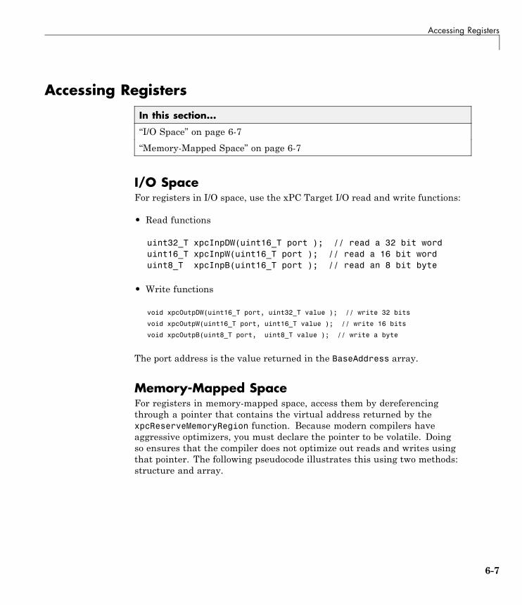
I/O SpaceFor registers in I/O space, use the xPC Target I/O read and write functions:
• Read functions
uint32_T xpcInpDW(uint16_T port ); // read a 32 bit worduint16_T xpcInpW(uint16_T port ); // read a 16 bit worduint8_T xpcInpB(uint16_T port ); // read an 8 bit byte
• Write functions
void xpcOutpDW(uint16_T port, uint32_T value ); // write 32 bits
void xpcOutpW(uint16_T port, uint16_T value ); // write 16 bits
void xpcOutpB(uint8_T port, uint8_T value ); // write a byte
The port address is the value returned in the BaseAddress array.
Memory-Mapped SpaceFor registers in memory-mapped space, access them by dereferencingthrough a pointer that contains the virtual address returned by thexpcReserveMemoryRegion function. Because modern compilers haveaggressive optimizers, you must declare the pointer to be volatile. Doingso ensures that the compiler does not optimize out reads and writes usingthat pointer. The following pseudocode illustrates this using two methods:structure and array.
6-7
6 Custom xPC Target™ Driver Notes
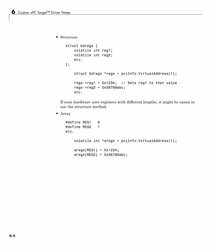
• Structure
struct bdregs {volatile int reg1;volatile int reg2;etc.
};
struct bdregs *regs = pciInfo.VirtualAddress[1];
regs->reg1 = 0x1234; // Sets reg1 to that valueregs->reg2 = 0x56789abc;etc.
If your hardware uses registers with different lengths, it might be easier touse the structure method.
• Array
#define REG1 0#define REG2 1etc.
volatile int *aregs = pciInfo.VirtualAddress[1];
aregs[REG1] = 0x1234;aregs[REG2] = 0x56789abc;
6-8
7
Creating Custom DriversUsing the xPC TargetDriver Authoring Tool
• “xPC Target Driver Authoring Tool” on page 7-2
• “Generating Custom Driver Templates” on page 7-4
7 Creating Custom Drivers Using the xPC Target™ Driver Authoring Tool
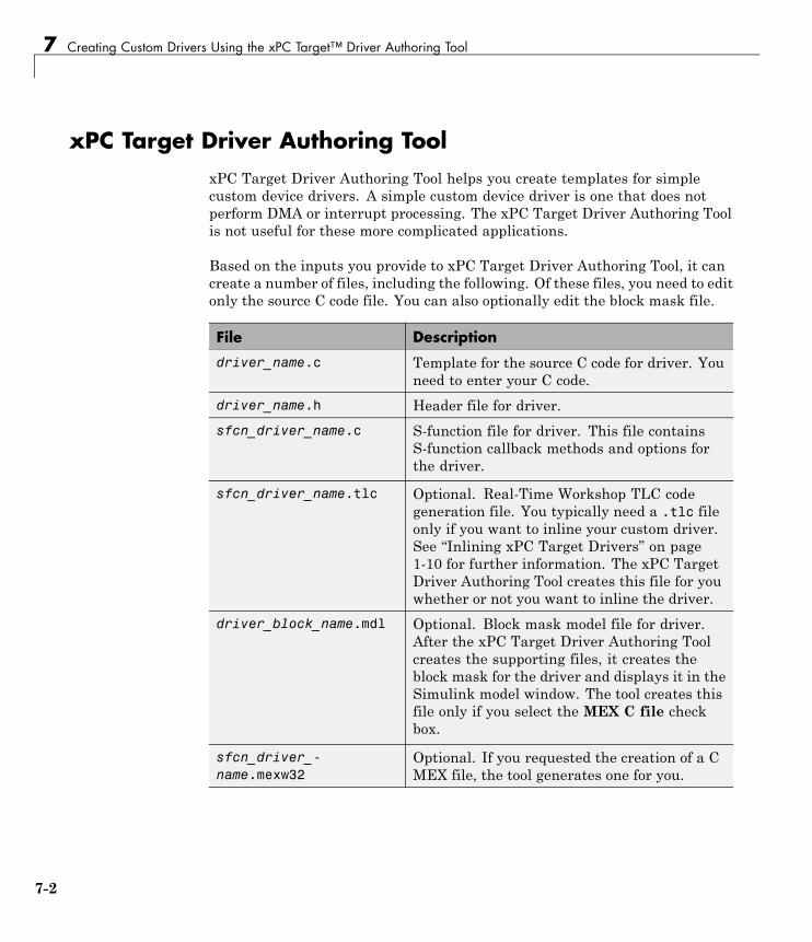
xPC Target Driver Authoring ToolxPC Target Driver Authoring Tool helps you create templates for simplecustom device drivers. A simple custom device driver is one that does notperform DMA or interrupt processing. The xPC Target Driver Authoring Toolis not useful for these more complicated applications.
Based on the inputs you provide to xPC Target Driver Authoring Tool, it cancreate a number of files, including the following. Of these files, you need to editonly the source C code file. You can also optionally edit the block mask file.
File Description
driver_name.c Template for the source C code for driver. Youneed to enter your C code.
driver_name.h Header file for driver.
sfcn_driver_name.c S-function file for driver. This file containsS-function callback methods and options forthe driver.
sfcn_driver_name.tlc Optional. Real-Time Workshop TLC codegeneration file. You typically need a .tlc fileonly if you want to inline your custom driver.See “Inlining xPC Target Drivers” on page1-10 for further information. The xPC TargetDriver Authoring Tool creates this file for youwhether or not you want to inline the driver.
driver_block_name.mdl Optional. Block mask model file for driver.After the xPC Target Driver Authoring Toolcreates the supporting files, it creates theblock mask for the driver and displays it in theSimulink model window. The tool creates thisfile only if you select the MEX C file checkbox.
sfcn_driver_-name.mexw32
Optional. If you requested the creation of a CMEX file, the tool generates one for you.
7-2
xPC Target™ Driver Authoring Tool
Note The xPC Target Driver Authoring Tool creates custom driver templatesusing the Legacy Code Tool (LCT). You do not need any prior knowledge of theLegacy Code Tool to use the xPC Target Driver Authoring Tool. If you want toread about the Legacy Code Tool, see “Integrating Existing C Functions intoSimulink Models with the Legacy Code Tool” in Developing S-Functions.
7-3
7 Creating Custom Drivers Using the xPC Target™ Driver Authoring Tool
Generating Custom Driver Templates
In this section...
“Using the xPC Target Driver Authoring Tool” on page 7-4
“Setting Up Driver Variables” on page 7-4
“Saving the Configuration” on page 7-7
“Reloading the Configuration” on page 7-8
“Creating the C File Template” on page 7-8
“Creating a C MEX File for the Driver” on page 7-8
“Customizing the Device Driver Mask” on page 7-9
Using the xPC Target Driver Authoring ToolThe prerequisites for creating a custom xPC Target device driver using thexPC Target Driver Authoring Tool are the same as those for creating a devicedriver manually. See “Expected Background” on page 1-3 and “Before YouStart” on page 1-8 for further information.
The following sections assume that you have identified the followingcomponent specifications for the driver. See “Before You Start” on page 1-8for guidelines for the following driver components, including their data typeand size:
Input portsOutput portsParametersWork variables
Setting Up Driver Variables
1 In the MATLAB Command Window, change directory to the one in whichyou want to save the driver code.
2 Start xPC Target Driver Authoring Tool. Type
xpcdrivertool
7-4
Generating Custom Driver Templates
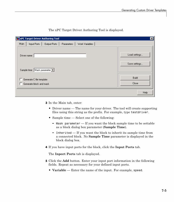
The xPC Target Driver Authoring Tool is displayed.
3 In the Main tab, enter:
• Driver name — The name for your driver. The tool will create supportingfiles using this string as the prefix. For example, type testdriver.
• Sample time — Select one of the following:
– Mask parameter— If you want the block sample time to be settableas a block dialog box parameter (Sample Time).
– Inherited — If you want the block to inherit its sample time froma connected block. No Sample Time parameter is displayed in theblock dialog box.
4 If you have input ports for the block, click the Input Ports tab.
The Inport Ports tab is displayed.
5 Click the Add button. Enter your input port information in the followingfields. Repeat as necessary for your defined input ports.
• Variable— Enter the name of the input. For example, speed.
7-5
7 Creating Custom Drivers Using the xPC Target™ Driver Authoring Tool
• Size — Enter the maximum size number of storage locations to beallocated for the parameter. If you want this number to be a variable one,enter a value of 0. This setting means that you can pass an additionalfunction argument that contains the size into the start, output, and/orterminate functions along with the port/parameter variable.
• Type— From the list, select the data type for the input port.
• Output— This check box is always selected. It ensures that the inputport value will be passed into the S-function mdlOutputs callbackmethod.
6 If you have output ports for the block, click the Output Ports tab.
The Output Ports tab is displayed.
7 Click the Add button. Enter your output port information in the followingfields. Repeat as necessary for your defined output ports.
• Variable— Enter the name of the output. For example, speed.
• Size — Enter the maximum size number of storage locations to beallocated for the size.
• Type— From the list, select the data type for the output port.
• Output— This check box is always selected. It ensures that the outputport value will be passed into the S-function mdlOutputs callbackmethod.
8 If you have parameters for the block, click the Parameters tab.
The Parameters tab is displayed.
9 Click the Add button. Enter your parameter information in the followingfields. Repeat as necessary for your defined parameters.
• Variable— Enter the name of the parameter. For example, speed.
• Type— From the list, select the data type for the parameter.
• Size — Enter the maximum size number of storage locations to beallocated for the parameter. If you want this number to be a variableone, enter a value of 0. This means that you can pass an additional
7-6
Generating Custom Driver Templates
function argument that contains the size into the start, output and/orterminate functions along with the port/parameter variable.
• Start — Select the check box if you want the parameter value to bepassed into the S-function mdlStart callback method.
• Output — Select the check box if you want the parameter value to bepassed into the S-function mdlOutputs callback method.
• Terminate— Select the check box if you want the parameter value tobe passed into the S-function mdlTerminate callback method.
10 If you have work variables to be shared between the start, output, andterminate routines for the block, click the Work Variables tab.
The Work Variables tab is displayed.
11 Click the Add button. Enter your work variables information in thefollowing fields. Repeat as necessary for your defined parameters.
• Variable— Enter the name of the work variable. For example, speed.
• Type— From the list, select the data type for the work variable.
• Size— Enter the maximum size of the work variable.
• Start— Select the check box if you want the work variable value to bepassed into the S-function mdlStart callback method.
• Output— Select the check box if you want the work variable value to bepassed into the S-function mdlOutputs callback method.
• Terminate— Select the check box if you want the work variable valueto be passed into the S-function mdlTerminate callback method.
Saving the ConfigurationThe xPC Target Driver Authoring Tool allows you to save your configurationsession as a MAT-file.
1 In the xPC Target Driver Authoring Tool, click the Main tab.
2 Click Save settings.
The tool saves the testdriver.mat file in the current working directory.
7-7
7 Creating Custom Drivers Using the xPC Target™ Driver Authoring Tool
You can iteratively change the configuration and resave the MAT-file as oftenas you like.
Reloading the ConfigurationThe xPC Target Driver Authoring Tool allows you to reload your configurationsession as a MAT-file.
1 In the xPC Target Driver Authoring Tool, click the Main tab.
2 Click Load settings.
The tool loads the testdriver.mat file into the tool.
Creating the C File TemplateTo generate a template for the driver C source code file:
1 In the xPC Target Driver Authoring Tool, click the Main tab.
2 Select Generate C file template.
3 Click the Build button.
The tool creates the following files:
• testdriver.c
• testdriver.h
• sfcn_testdriver.c
• sfcn_testdriver.tlc
4 With your favorite editor, open the testdriver.c file and edit it. This is thesource C code for your driver. The S-function code in sfcn_testdriver.cwill reference this C file.
Creating a C MEX File for the DriverTo create a C MEX file for the driver, you can use either the xPC TargetDriver Authoring Tool or the mex function.
7-8
Generating Custom Driver Templates
Note Use the xPC Target Driver Authoring Tool to build the C Mex file ifyou have not edited the C source code file (testdriver.c). If you have editedthis file and want to keep those changes, do not use the xPC Target DriverAuthoring Tool to build the driver. Doing so overwrites your changes to theC source code. Instead, use the mex function (see “Creating a C MEX FileUsing the mex Function” on page 7-9).
Creating a C MEX File Using the xPC Target Authoring Tool
1 In the xPC Target Driver Authoring Tool, click the Main tab.
2 Select Generate block and mask.
3 Click the Build button.
The tool creates the file sfcn_testdriver.mexw32.
Creating a C MEX File Using the mex Function
1 In the MATLAB Command Window, change directory to the one thatcontains the driver files.
2 Compile and link the MEX-file. For example:
mex sfcn_testdriver.c testdriver.c
This function creates the sfcn_testdriver.win32mex file.
Customizing the Device Driver MaskThe xPC Target Driver Authoring Tool creates a mask for the device driver.You can customize this block mask as described in Chapter 4, “MaskingDrivers”. If you customize the mask, do not use the xPC Target DriverAuthoring Tool again to build your files. Doing so overwrites the driver filesand you will lose your mask customizations.
7-9

7 Creating Custom Drivers Using the xPC Target™ Driver Authoring Tool
7-10
8
I/O Structures — ByCategory
xpcPCIDevice Type definition for PCI configurationspace structure
xpcTime Type definition of time structure

8 I/O Structures — By Category
8-2

9
I/O Structures —Alphabetical List
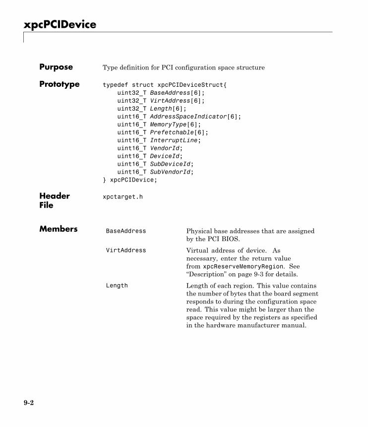
xpcPCIDevice
Purpose Type definition for PCI configuration space structure
Prototype typedef struct xpcPCIDeviceStruct{uint32_T BaseAddress[6];uint32_T VirtAddress[6];uint32_T Length[6];uint16_T AddressSpaceIndicator[6];uint16_T MemoryType[6];uint16_T Prefetchable[6];uint16_T InterruptLine;uint16_T VendorId;uint16_T DeviceId;uint16_T SubDeviceId;uint16_T SubVendorId;
} xpcPCIDevice;
HeaderFile
xpctarget.h
Members BaseAddress Physical base addresses that are assignedby the PCI BIOS.
VirtAddress Virtual address of device. Asnecessary, enter the return valuefrom xpcReserveMemoryRegion. See“Description” on page 9-3 for details.
Length Length of each region. This value containsthe number of bytes that the board segmentresponds to during the configuration spaceread. This value might be larger than thespace required by the registers as specifiedin the hardware manufacturer manual.
9-2
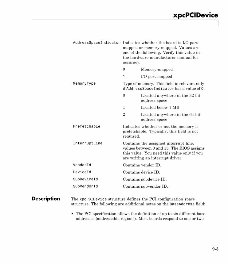
xpcPCIDevice
Indicates whether the board is I/O portmapped or memory-mapped. Values areone of the following. Verify this value inthe hardware manufacturer manual foraccuracy.
0 Memory-mapped
AddressSpaceIndicator
1 I/O port mapped
Type of memory. This field is relevant onlyif AddressSpaceIndicator has a value of 0.
0 Located anywhere in the 32-bitaddress space
1 Located below 1 MB
MemoryType
2 Located anywhere in the 64-bitaddress space
Prefetchable Indicates whether or not the memory isprefetchable. Typically, this field is notrequired.
InterruptLine Contains the assigned interrupt line,values between 0 and 15. The BIOS assignsthis value. You need this value only if youare writing an interrupt driver.
VendorId Contains vendor ID.
DeviceId Contains device ID.
SubDeviceId Contains subdevice ID.
SubVendorId Contains subvendor ID.
Description The xpcPCIDevice structure defines the PCI configuration spacestructure. The following are additional notes on the BaseAddress field:
• The PCI specification allows the definition of up to six different baseaddresses (addressable regions). Most boards respond to one or two
9-3
xpcPCIDevice
of these addresses. Base addresses are filled in during the BIOSplug and play initialization, before the xPC Target kernel starts toexecute. The hardware designer of the board decides how manyaddress spaces are defined and what they are used for. Many boardsuse one address space to contain all of the registers for the board,other boards separate functions into different address spaces. Seethe board hardware manufacturer manual for this information.
• For memory-mapped segments, call the xpcReserveMemoryRegionfunction to convert the physical address in BaseAddress to a virtualaddress that is suitable for the CPU to read and write the segment.You can then optionally save this address in the VirtAddress field.You might want to save the address if you have several segments andyou want to pass them all to a board access library.
See Also xpcGetPCIDeviceInfo, xpcShowPCIDeviceInfo
9-4
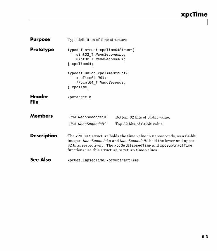
xpcTime
Purpose Type definition of time structure
Prototype typedef struct xpcTime64Struct{uint32_T NanoSecondsLo;uint32_T NanoSecondsHi;
} xpcTime64;
typedef union xpcTimeStruct{xpcTime64 U64;//uint64_T NanoSeconds;
} xpcTime;
HeaderFile
xpctarget.h
Members U64.NanoSecondsLo Bottom 32 bits of 64-bit value.
U64.NanoSecondsHi Top 32 bits of 64-bit value.
Description The xPCTime structure holds the time value in nanoseconds, as a 64-bitinteger. NanoSecondsLo and NanoSecondsHi hold the lower and upper32 bits, respectively. The xpcGetElapsedTime and xpcSubtractTimefunctions use this structure to return time values.
See Also xpcGetElapsedTime, xpcSubtractTime
9-5

xpcTime
9-6
10
I/O Functions — ByCategory
Port I/O (p. 10-2) I/O port input and output functionsfor byte, word and double wordaccesses
PCI Configuration Information(p. 10-2)
Work with PCI devices through thePCI configuration space
Physical Memory (p. 10-2) PCI memory management functions
Time (p. 10-2) xPC Target timing functions
Miscellaneous (p. 10-3) Miscellaneous functions
10 I/O Functions — By Category
Port I/OxpcInpB, xpcInpW, xpcInpDW I/O port input functions for byte,
word, and double word accesses
xpcOutpB, xpcOutpW, xpcOutpDW I/O port output functions for byte,word, and double word accesses
PCI Configuration InformationxpcGetPCIDeviceInfo Return information for PCI device
xpcShowPCIDeviceInfo Display contents of PCIDevicestructure
Physical MemoryxpcAllocPhysicalMemory Allocate physical memory
xpcFreePhysicalMemory Free physical memory
xpcReserveMemoryRegion Return virtual address thatcorresponds to physical address andmark region as readable/writable
TimexpcGetElapsedTime Return time since system boot
xpcSubtractTime Return difference between two times
10-2
Miscellaneous
MiscellaneousxpcBusyWait Wait for specified length of time in
seconds
xpcIsModelInit Return target application load state
10-3

10 I/O Functions — By Category
10-4

11
I/O Functions —Alphabetical List

xpcAllocPhysicalMemory
Purpose Allocate physical memory
Prototype void *xpcAllocPhysicalMemory(uint32_T numBytes)
HeaderFile
xpctarget.h
Arguments numBytes Allocate specified number of bytes of memory.
Description The xpcAllocPhysicalMemory function allocates the requested bytesof physical memory. Functions such as malloc only return virtualmemory.
xPCAllocPhysicalMemory allocates physical memory, where physicalmemory is the same as the virtual address. Use this function only whenabsolutely necessary, such as for DMA transfers.
See Also xpcFreePhysicalMemory
11-2
xpcBusyWait
Purpose Wait for specified length of time in seconds
Prototype void xpcBusyWait(real_T seconds)
HeaderFile
xpctarget.h
Arguments seconds Length of time to wait, in seconds.
Description The xpcBusyWait function waits for the specified number of seconds.This function blocks this specified amount of time.
11-3
xpcFreePhysicalMemory
Purpose Free physical memory
Prototype void xpcFreePhysicalMemory(const void *physical)
HeaderFile
xpctarget.h
Arguments physical Free specified memory.
Description The xpcFreePhysicalMemory function frees the specified section ofphysical memory.
See Also xpcAllocPhysicalMemory
11-4
xpcGetElapsedTime
Purpose Return time since system boot
Prototype real_T xpcGetElapsedTime(xpcTime *upTime)
Arguments upTime Pointer to an xpcTime structure.
Description The xpcGetElapsedTime function returns the time since the systemwas last booted, in seconds. You can get this time in nanoseconds bypassing a pointer to a previously allocated xpcTime structure. You canpass a NULL pointer for the upTime argument if you do not want thetime in nanoseconds.
See Also xpcTime, xpcSubtractTime
11-5
xpcGetPCIDeviceInfo
Purpose Return information for PCI device
Prototype int32_T xpcGetPCIDeviceInfo (uint16_T vendorId, uint16_TdeviceId, uint16_T subVendorId, uint16_T subDeviceId,uint16_T bus, uint16_T slot, xpcPCIDevice *pciInfo);
Arguments vendorId Enter the vendor ID.
deviceId Enter the device ID.
subVendorId Enter the subvendor ID.
subDeviceId Enter the subdevice ID.
bus Enter the device bus.
slot Enter the slot that contains the device.
pciInfo Pointer to the PciDevice structure.
HeaderFile
xpctarget.h
Description The xpcGetPCIDeviceInfo function fills the structure, pciInfo, withthe PCI configuration information for the specified PCI device. Thisinformation includes base address, registers, IRQ, and so forth fromthe PCI BIOS. It uses the vendor and device IDs and, optionally, thesubvendor and subdevice IDs to search for the board.
If you specify XPC_NO_SUB for the subvendor or subdevice ID, orXPC_NO_BUS_SLOT for the device slot, the function will search throughthe PCI BIOS and return the first board that it finds with the specifiedIDs. If you specify a bus and a slot value, the function will successfullyreturn only a board with the matching IDs found at that bus or slot.
You must supply valid vendor and device IDs. If you specify valuesother than XPC_NO_SUB for subvendor and subdevice IDs, the functionwill match the board using all four ID parameters. To find a board
11-6
xpcGetPCIDeviceInfo
using only vendor ID and device ID, use XPC_NO_SUB for subDeviceIdand XPC_NO_SUB for subVendorId.
This function returns 0 upon success. Otherwise, it returns a nonzerovalue.
See Also xpcPCIDevice xpcShowPCIDeviceInfo
11-7
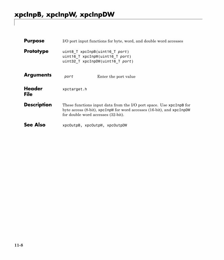
xpcInpB, xpcInpW, xpcInpDW
Purpose I/O port input functions for byte, word, and double word accesses
Prototype uint8_T xpcInpB(uint16_T port)uint16_T xpcInpW(uint16_T port)uint32_T xpcInpDW(uint16_T port)
Arguments port Enter the port value
HeaderFile
xpctarget.h
Description These functions input data from the I/O port space. Use xpcInpB forbyte access (8-bit), xpcInpW for word accesses (16-bit), and xpcInpDWfor double word accesses (32-bit).
See Also xpcOutpB, xpcOutpW, xpcOutpDW
11-8
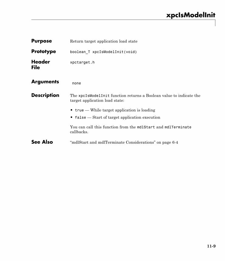
xpcIsModelInit
Purpose Return target application load state
Prototype boolean_T xpcIsModelInit(void)
HeaderFile
xpctarget.h
Arguments none
Description The xpcIsModelInit function returns a Boolean value to indicate thetarget application load state:
• true — While target application is loading
• false — Start of target application execution
You can call this function from the mdlStart and mdlTerminatecallbacks.
See Also “mdlStart and mdlTerminate Considerations” on page 6-4
11-9
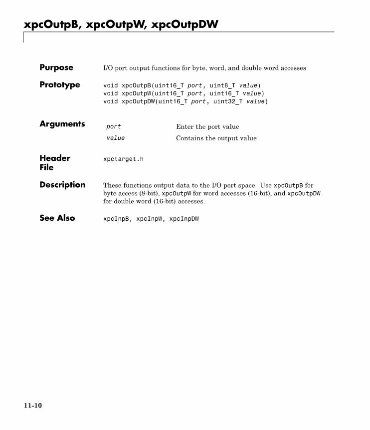
xpcOutpB, xpcOutpW, xpcOutpDW
Purpose I/O port output functions for byte, word, and double word accesses
Prototype void xpcOutpB(uint16_T port, uint8_T value)void xpcOutpW(uint16_T port, uint16_T value)void xpcOutpDW(uint16_T port, uint32_T value)
Arguments port Enter the port value
value Contains the output value
HeaderFile
xpctarget.h
Description These functions output data to the I/O port space. Use xpcOutpB forbyte access (8-bit), xpcOutpW for word accesses (16-bit), and xpcOutpDWfor double word (16-bit) accesses.
See Also xpcInpB, xpcInpW, xpcInpDW
11-10
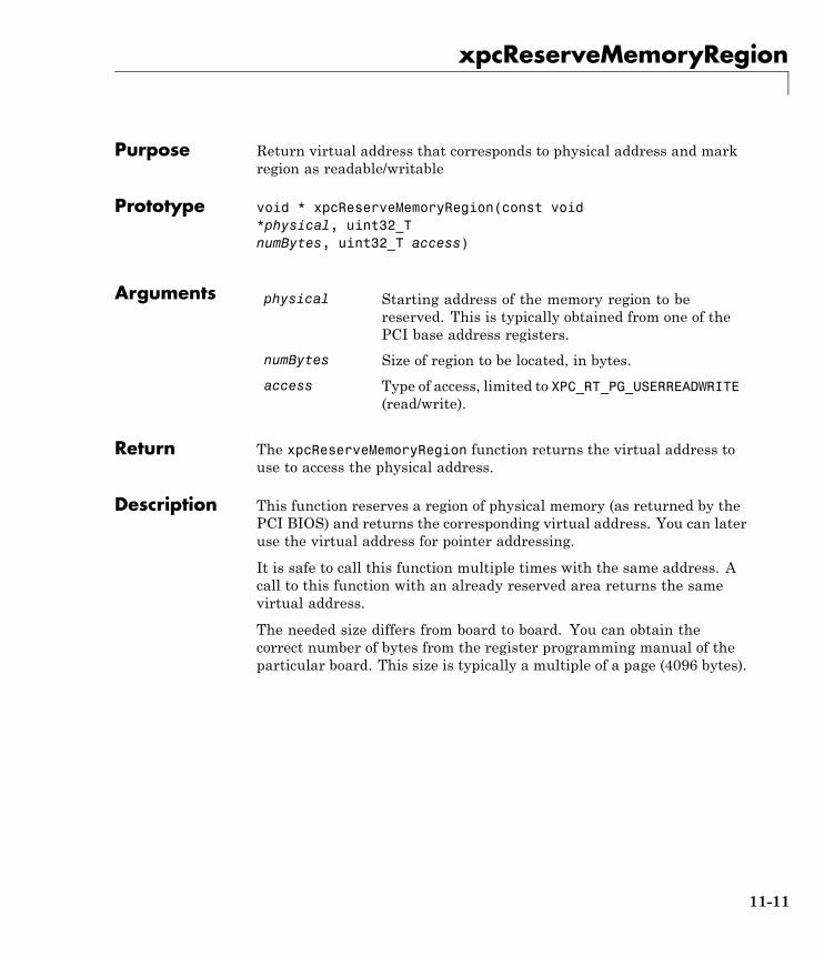
xpcReserveMemoryRegion
Purpose Return virtual address that corresponds to physical address and markregion as readable/writable
Prototype void * xpcReserveMemoryRegion(const void*physical, uint32_TnumBytes, uint32_T access)
Arguments physical Starting address of the memory region to bereserved. This is typically obtained from one of thePCI base address registers.
numBytes Size of region to be located, in bytes.
access Type of access, limited to XPC_RT_PG_USERREADWRITE(read/write).
Return The xpcReserveMemoryRegion function returns the virtual address touse to access the physical address.
Description This function reserves a region of physical memory (as returned by thePCI BIOS) and returns the corresponding virtual address. You can lateruse the virtual address for pointer addressing.
It is safe to call this function multiple times with the same address. Acall to this function with an already reserved area returns the samevirtual address.
The needed size differs from board to board. You can obtain thecorrect number of bytes from the register programming manual of theparticular board. This size is typically a multiple of a page (4096 bytes).
11-11
xpcShowPCIDeviceInfo
Purpose Display contents of PCIDevice structure
Prototype void xpcShowPCIDeviceInfo(xpcPCIDevice *pciInfo)
Arguments pciInfo Pointer to the xpcPCIDevice structure.
Description This debugging function displays the contents of the PCIDevicestructure pointed to by pciInfo. You can use this function withthe xpcGetPCIDeviceInfo function to display the contents of thexpcPCIDevice structure.
Note Remove this function from the driver before deploying.
See Also xpcGetPCIDeviceInfo
11-12
xpcSubtractTime
Purpose Return difference between two times
Prototype real_T xpcSubtractTime(xpcTime *time,const xpcTime *time2, const xpcTime *time1)
Arguments time Pointer to an xpcTime structure.
time2 Enter the time to subtract.
time1 Enter the time to subtract from.
Description xpcSubtractTime returns the difference between time1 and time2(time2 - time1), in seconds. You can get this time in nanoseconds bypassing a pointer to a previously allocated xpcTime structure. You canpass a NULL pointer for the time argument if you do not want thetime in nanoseconds.
See Also xpcTime, xpcGetElapsedTime
11-13