Embed Size (px)
Citation preview

What's New
2017


What's New in Advance Design 2017
3
Table of Contents
NEW ....................................................................................................................................................... 5
GRAITEC Advance BIM Designers .................................................................................................................... 5 The Advance Design - Advance BIM Designers Workflow ............................................................................. 8 Output: Calculation Results Tab ................................................................................................................... 13 BIM Designer Reports ................................................................................................................................... 14 Advance BIM Designers - Advance Design Synchronization ....................................................................... 14 Steel Connection Designer ........................................................................................................................... 15 Structure Designer ........................................................................................................................................ 17
Graitec Grid Control .......................................................................................................................................... 18
New Load Groups for the Moving Loads Generator ......................................................................................... 19
Ability to disable an element for the calculation ............................................................................................... 25
Simplified workflow to define rigid elements ..................................................................................................... 27
Additional information in planar elements tooltip .............................................................................................. 29
Easily expand or collapse element properties .................................................................................................. 30
MISCELLANEOUS IMPROVEMENTS & CORRECTIONS ............................................................................... 31
General application ........................................................................................................................................... 31
CAD .................................................................................................................................................................. 31
Climatic generator ............................................................................................................................................. 31
Post-processing ................................................................................................................................................ 33
Reports ............................................................................................................................................................. 33
Concrete analysis ............................................................................................................................................. 34
Steel analysis .................................................................................................................................................... 35
Import / Export .................................................................................................................................................. 36


What's New in Advance Design 2017
5
New
GRAITEC Advance BIM Designers The GRAITEC Advance 2017 suite features the GRAITEC Advance BIM Designers, a brand-new collection of vertical applications which offers the possibility to design reinforced concrete elements (footings, beams and columns), steel connections and to generate new steel structures in just a few clicks. These new modules are multiplatform and can run as standalone modules, embedded in Autodesk Revit® or embedded in Advance Design. This allows the user to achieve a streamline BIM workflow for all its structural projects:
The 2017 version of Advance Design offers the possibility to embed the modules directly within the FEM application. With the new GRAITEC Advance BIM Designers, users can automatically design elements, generate reinforcement drawings in the case of RC elements and produce comprehensive reports with exhaustive details about every verification performed in the design process, with the corresponding articles relating to the applied design code.
In Advance Design 2017, the new “Design” tab in the ribbon becomes active once the Advance BIM Designers modules are enabled.
The “Design” mode now available in the Pilot, activates the Advance BIM Designers modules and displays each list of all the elements that can be designed using the new BIM Designers modules.
What's New in Advance Design 2017
6
You can achieve the entire design process within Advance Design:
Important! In version 2017, the BIM Designers modules are “pre-released”, allowing customers to access and test this brand new technology. The modules will be officially released with version 2017 R2 coming soon, in September 2016.

What's New in Advance Design 2017
7
The objective of this “What’s New” document is to offer a global overview of the BIM Designers capabilities. You can find more detailed information in the help section of each module, available directly from the “Design” ribbon in Advance Design:
The Help describes the functionalities of the standalone BIM Designers modules, as well as the specificities of the modules when running in Advance Design and when running in Revit®:

What's New in Advance Design 2017
8
The Advance Design - Advance BIM Designers Workflow The time needed to design the elements is significantly decreased because all the relevant design assumptions can be transferred from Advance Design to Advance BIM Designers: geometry, concrete covers, fire assumptions, buckling length and so on. The efforts resulting from FEM calculation are also transferred to Advance BIM Designers.
The new GRAITEC BIM Designers allows the application of two different workflows, together with Advance Design:
• Using the new design tools directly in Advance Design: In this case, the user can start the project in Advance Design and run a finite element analysis to get the internal forces and be able to design the elements with the integrated BIM Designers:
• Starting the model in Advance Design and exporting the elements to the BIM Designers to be used in a
standalone mode. Such a workflow is compliant with a multi-user process and allow the engineer to continue working in Advance Design while another one designs the elements with the BIM Designers standalone version:
There are also several other BIM workflows which can be applied with GRAITEC BIM Designers including the Autodesk Revit® BIM platform:

What's New in Advance Design 2017
9
Innovative technology designed to increase productivity, is the option to assign each Advance Design element (column, beam or footing) to an Advance BIM Designers template. These user-created templates include the design assumptions specific to each structural element and are applied when the element is loaded in Advance BIM Designers.
In certain situations, the user doesn’t generate all required combinations for element design directly into Advance Design. To ensure that all necessary combinations are used to design an element, they have been defined directly into Advance BIM Designers, through the loads and combinations dialogs:

What's New in Advance Design 2017
10
Concrete elements Once the FEM analysis is complete, the user can open any element from the model by applying the new “Open with BIM Designers” command from the contextual menu.
Three types of concrete elements can be calculated using the Advance BIM Designers: footings (continuous and isolated), beams and columns.
The unavoidable step before running a structural design session is to define the structural design assumptions.
Structural design assumptions can be split in two different families:
Design codes assumptions (Design Assumptions)

What's New in Advance Design 2017
11
Constructive dispositions for the automatic placement of bars inside concrete members (Reinforcement Assumptions)
Both assumption families are country-code dependent (Eurocodes with different national appendixes, US codes, Canadian codes).
When all assumptions are set, the user can calculate the model. Advance BIM Designers will automatically generate the reinforcement needed for the efforts transferred from Advance Design.

What's New in Advance Design 2017
12
After the reinforcement is generated, the user still has the option to adjust it. The reinforcement can easily be modified or new bars can be added, with the possibility to see if the area of modified bars exceeds the theoretical area calculated by Advance BIM Designers.
The calculated reinforcement can be restored at any point by using the “Restore from calculation” option.

What's New in Advance Design 2017
13
Output: Calculation Results Tab For each verification performed, the "Calculation results" tab displays the work ratio, resistance, effort and combination.
Once the element is calculated, the user can display the drawing on screen, print it or save the drawing on the computer.
On the drawing, the program automatically creates a bar schedule and a title block with all the information about the project and the element (this information will be imposed in “Project Settings” from Advance BIM Designers).

What's New in Advance Design 2017
14
BIM Designer Reports One of the greatest features of Advance BIM Designers is producing a set of available reports.
Users can preview reports using the Report Designer tool, or export them in DOC or PDF format.
Advance BIM Designers - Advance Design Synchronization There are various reasons why the geometry of an element or the material would be changed in Advance BIM Designers.
The user could choose to transfer all these assumptions to Advance Design, or leave them in Advance BIM Designers. If the user chooses to transfer the new assumptions in Advance Design, the FEM results will be obsolete.
For situations when the user chooses to redo the FEM analysis but wants to keep the work performed in Advance BIM Designers, the “Variant” option is available in “Project settings”.
Using this option, the user can save different versions of the same BIM Designers element calculated with different efforts and assumptions. The files are saved in the “Design” folder of each project.

What's New in Advance Design 2017
15
Steel Connection Designer Advance Design 2017 users are able to calculate steel joints using a specific Advance BIM Designers module: Steel Connection Designer.
Connections must be defined directly in the Advance Design descriptive model before the joint can be designed using the Steel Connection Designer.
The module can run specific checks according to Eurocodes 3 rules, for 3 types of connections: base plate, moment end plate and apex haunch.
Base plate This joint is created by welding a steel plate to the bottom end of the column which is connected to the foundations through anchors. The joint can include several reinforcement plates, shim plate or shear anchor.
Moment End Plate This connection is used to connect a tie beam to a column. The moment connection creates additional support (i.e., welds, plates, stiffeners) to the connection.

What's New in Advance Design 2017
16
Apex Haunch Usually, this joint is used for roof beams. It consists of two beams spliced with bolted end-plates, and haunches attached at the bottom. The haunches are created from beams or plates.
Geometry customization The user can customize each element of the joint using the available buttons from the “Geometry” dialog box. For example, the user can set the geometry of the plates and stiffeners, choose the material of the elements or set the configuration of bolts/anchors.

What's New in Advance Design 2017
17
Structure Designer
A new functionality available in Advance Design 2017 is the Steel Structure Designer, a valuable application that incorporates an extensive range of building definitions and tools enabling users to configure complete steel structures in seconds.
Some of the most important features of the Steel Structure Designer are: Setting the number of levels, bays in each level, and rows in each bay, and easily amending the
distances between them. Amending the portal width and height, the roof type, number of beams, slope and alignment. Aligning gable posts and adjusting side bracings, side rails and purlins. Creating roof bracings and curved roofs.

What's New in Advance Design 2017
18
Graitec Grid Control
Advance Design 2017 introduces a brand-new way to modify the properties of each type of element from the model: the Grid Control tool. In version 2017, the user can only access the geometry of the model: element’s name, system, type, geometrical position, material, section releases, load properties and supports properties.
When defining the properties to be displayed on the grid, the user can save a template which can be applied afterwards on other models.
All the displayed properties can be modified directly in the Graitec Grid Control, or the information can be exported to Microsoft Excel and modified using Excel commands. The user then has the option to update the Advance Design model:
Note: In the next versions of Advance Design, this new functionnality will also be extended to results.

What's New in Advance Design 2017
19
New Load Groups for the Moving Loads Generator The moving loads generator implemented in Advance Design 2016 SP1 has been improved.
It now comes with 3 additional load groups defined in EN1991-2 (Section 4):
• Group 2: Load Model 1 with horizontal forces
• Group 3: Footways and cycle-tracks
• Group 4: Crowd loading
Load Group 2 Load group 2 is a combination of
Load Model 1 (Tandem System + Uniformly Distributed Load) Horizontal forces
− Longitudinal forces (acceleration or braking) − Centrifugal forces
Note: Centrifugal forces are only generated on curved traffic lanes.

What's New in Advance Design 2017
20
When traffic loads are set on Group 2, the carriageway definition dialog can automatically detect the traffic lanes and the remaining areas in order to generate the appropriate loads.
Traffic lanes
Footways or cycle tracks Remaining areas
Note: Group 2 does not involve loads on Footways or cycle-tracks, therefore, the “Auto” button is greyed-out.

What's New in Advance Design 2017
21
Uniformy Distributed Loads on traffic lanes and remaning area
Tandem Systems on traffic lanes
Acceleration forces on traffic lanes

What's New in Advance Design 2017
22
Load Group 3
Group 3 is made up of the uniformly distributed load on footways or cycle tracks.
When traffic loads are set on Group 3, the carriageway definition dialog will automatically detect footways and cycle-tracks in order to generate the appropriate loads.
Uniformy Distributed Loads on footways and cycle-tracks

What's New in Advance Design 2017
23
Note: Footways are defined by creating a traffic lane and activating the “Footway” property.
Load Group 4 Load group 4 is a combination of
Load Model 4 (crowd loading) which is a 5 kN/m3 uniformly Distributed Load Loads on footways and cycle-tracks

What's New in Advance Design 2017
24
The user must define a traffic panel to specify the area where the crowd loading will be applied.
When traffic loads are set on Group 4, the carriageway definition dialog will automatically detect footways and cycle-tracks as well as the remaning areas in order to generate the appropriate loads.
Crowd loading on the carriageway and UDLs on footways

What's New in Advance Design 2017
25
Other improvements on traffic lane definition A “Radius” parameter has added to traffic lane properties to allow for curved elements (#16917).
Ability to disable an element for the calculation Advance Design 2017 now enables the user to deactivate one or several elements in the calculation without removing them from the model.
Users can now easily try multiple building configurations without having to create multiple models
A new “Active state” property has been introduced in the property sheet of structural elements : linear elements planar elements supports
When active (default state), the element is taken into account in the analysis model.

What's New in Advance Design 2017
26
When inactive, all element properties are greyed-out and inactive.
Although the element is still visible in Model phase, it will no longer be displayed once in Analysis phase.
Notes: 1. The self-weight of the inactive elements is not considered in the analysis model.
2. The new “Active state” feature is not compatible with calculation by phases, as calculation by phases in Advance Design does not allow for adding or removing elements between steps.

What's New in Advance Design 2017
27
Simplified workflow to define rigid elements Advance Design 2017 simplifies the process by which the user defines rigid elements in a model.
A new “rigid” entry is now available for the linear element type:
When selected, the linear element will automatically be assigned: a RIGID cross-section the RIGID material
The “Rigid” material is a material from the Advance Design database with high stiffness but no density.

What's New in Advance Design 2017
28
The “RIGID” cross-section is a cross-section from the Advance Design database with a very large area and inertia.
Defining an element as a rigid element will automatically disable the meshing properties, ensuring that there are no intermediate nodes along the rigid element.
What's New in Advance Design 2017
29
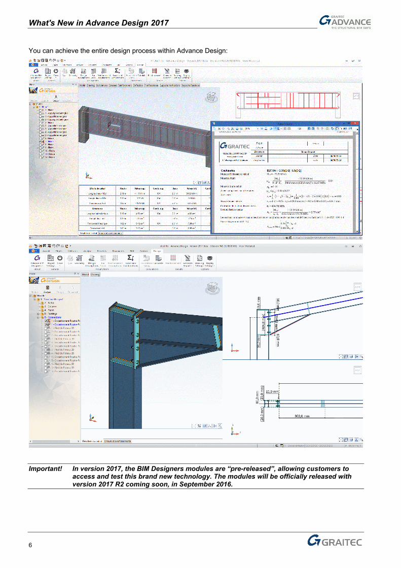
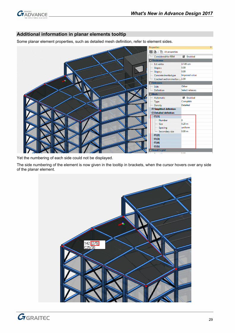
Additional information in planar elements tooltip Some planar element properties, such as detailed mesh definition, refer to element sides.
Yet the numbering of each side could not be displayed.
The side numbering of the element is now given in the tooltip in brackets, when the cursor hovers over any side of the planar element.
What's New in Advance Design 2017
30
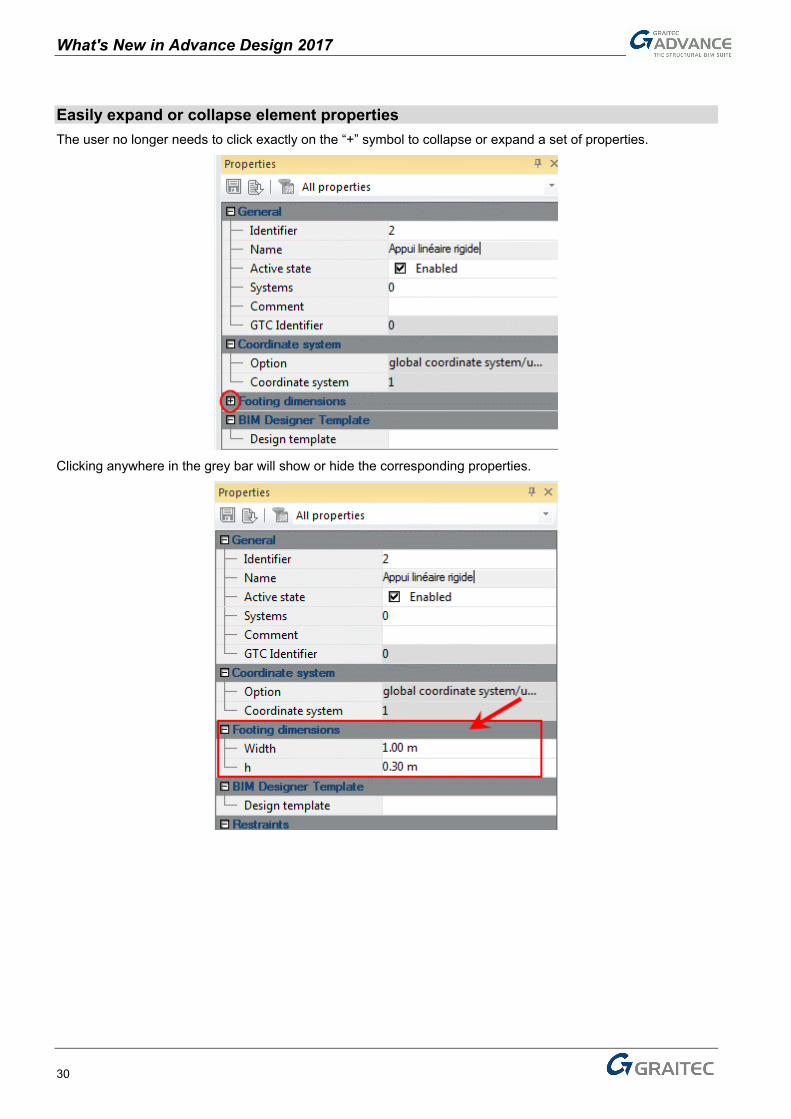
Easily expand or collapse element properties The user no longer needs to click exactly on the “+” symbol to collapse or expand a set of properties.
Clicking anywhere in the grey bar will show or hide the corresponding properties.

What's New in Advance Design 2017
31
Miscellaneous Improvements & Corrections
ADVANCE Design 2017 offers more than 120 improvements and corrections.
General application Improvement: it is now possible to unselect an element in the pilot by left-clicking it while pressing the
CTRL key (#14123). Correction: The legend for cross section is now correctly displayed (#17001).
CAD Improvement: the CAD functions section of the Home ribbon now features icons for the Symmetry and
Rotation functions (#16951).
Improvement: the Extrude dialog would not close after an illogical request from the user (e.g. element
in the XZ plane to be extruded around Y) (#16820). Improvement: openings can now be stretched using their snap points (#16636).
Climatic generator Correction: the CsCd structural factor is now applied on parapet walls (#16706).

What's New in Advance Design 2017
32
Correction: wind forces were missing on parapet walls supported by a duo-pitch canopy (#16550).
Correction: multiple windwalls with a slope < 5° are now properly considered as flat roofs instead of
sheds (#16432).
Correction: the G area was missing on flat roofs with parapet walls (#16706).

What's New in Advance Design 2017
33
Post-processing Improvement: two new envelope types have been implemented in the envelope load cases dialog.
Concomitant max (algebraic) will store the max values (biggest positive values) while Concomitant min (algebraic) will store the Min values (biggest negative values) (#16407).
Max algebraic Min algebraic
On a 2-span beam, these envelopes would be useful to get the critical moments on supports and in span
Correction: results were not available if the file name featured a “.” character (e.g. “test..fto”) (#16728).
Reports Correction: the Rules description table now properly displays the rules defined by the user in the Rules
definition dialog (#15645).

What's New in Advance Design 2017
34
Concrete analysis Correction: the ColorMap Configuration function was not working properly on reinforcement values
(#16263).
Improvement: the reinforcement dialog has been redesigned to allow for more room for the Definition
by area and by Bars (#16803).
Correction: the finite element results from the calculation report would not take into account the
Clipping of forces option when activated (#16752). Improvement: the “Delta Ays (Ays theo – Ayi real)-“ entry has been added to the list of the available
Real Reinforcement results. This entry points out the over reinforced areas on a model (with negative values) (Ref. 16795).

What's New in Advance Design 2017
35
Steel analysis Improvement: the default design templates have been updated to include the Eurocode 3 Global-sway
imperfections parameters (#16995).
Improvement: the Eurocode 3 lateral-torsional buckling dialog now lets the user enters decimal values
such as “0.5” by tapping “.5” (#16607) Correction: the “Stored shapes” table from the Steel Analysis results is no longer empty (#16815).
Correction: The slenderness value is now correctly calculated according to AISC (#16960).

What's New in Advance Design 2017
36
Import / Export Improvement (for France and Romania): the out-of-plane moment can now be taken into account when
exporting a shear wall from Advance Design 2017 to ARCHE Shear Wall (#16883).
Correction: The offset value for a linear element is correctly transferred to Autodesk Advance Steel
using .smlx (#16981).