Embed Size (px)
Citation preview
Vortex-Induced Vibrations of a Flexible Cylinder Experiencing an Oscillatory Flow
Bowen Fu1, Decheng Wan1*, Zhiqiang Hu2 1 State Key Laboratory of Ocean Engineering, School of Naval Architecture, Ocean and Civil Engineering, Shanghai Jiao Tong University,
Collaborative Innovation Center for Advanced Ship and Deep-Sea Exploration, Shanghai, China 2 School of Marine Science and Technology, Newcastle University, United Kingdom
* Corresponding author
ABSTRACT The CFD simulations of vortex-induced vibrations of a flexible cylinder in oscillatory flow have been numerically investigated based on the strip theory. The algorithm PIMPLE in OpenFOAM is adopted to compute the flow field while the small displacement Bernoulli–Euler bending beam theory is used to model the cylinder. Two ends of the flexible cylinder are forced to oscillate harmonically. Features such as the hysteresis between the decelerating and the accelerating stages and the build-up–lock-in–die-out cycle are observed. KEY WORDS: Vortex-induced vibration; oscillatory flow; flexible cylinder; computational fluid dynamics; fluid-structure interaction; viv-FOAM-SJTU solver INTRODUCTION Deep water structures can experience Vortex-Induced Vibrations (VIV) when exposed to marine currents. The engineering challenges of VIV for marine risers are of great concern as oil exploration moves to increasingly deeper waters. Experimental studies of vortex-induced vibrations of long flexible cylinders (the riser pipes) subjected to uniform, sheared, and stepped current profiles have been undertaken (Chaplin et al., 2005; Huera-Huarte et al., 2006; Huera-Huarte & Bearman, 2009). Complex phenomena such as multi-mode responses or time-sharing properties and traveling waves along the span of cylinders have been observed. In practice, offshore floating structures subjected to waves, currents or winds may cause the cylinders to move periodically in the water, then to generate relatively oscillatory flows between the cylinders and the water. Such relative oscillatory flows can play an important part in the vibrations of the flexible cylinders. For a steel catenary riser, the heaving of the floating platform can form relatively vertical oscillatory flows between the sag-bend of the riser and the water. The vibrations of cylinders in this type of time-varying currents can be intricate and quite different from those in constant flows. The time-varying current speeds
imply that the vortex shedding frequencies keep going up and down (excitation frequencies). When the vortex shedding frequencies meet one of the cylinder’s natural frequencies, lock-in or resonance phenomena occur. The vibrations of short rigid cylinders in elastic supporting conditions experiencing oscillatory flows have been extensively studied (Sumer & Fredse, 1997). However, only a few investigations into flexible cylinders such as Gonzalez (2001) have been conducted. Gonzalez (2001) numerically simulated the vibrations of a steel catenary riser in oscillatory flows using the Finite Element Method. A model test was also undertaken but only the top tensions were measured. Recently, a series of detailed model tests of a flexible cylinder in oscillatory flows have been conducted in Shanghai Jiao Tong University (Wang et al., 2014; Fu et al., 2014). In the present work, we numerically investigate vortex-induced vibrations of a flexible cylinder subjected to oscillatory flows using a computational fluid dynamics method, with similar parameters to the model test by Wang et al. (2014). The simulations are based on the in-house solver viv-FOAM-SJTU, which has been validated in previous studies such as Duan et al. (2016a), Duan et al. (2016b), and Fu et al. (2016). The present article is organized as followed. Section PROBLEM introduces the concerned problems, followed by the simulation methods in Section METHOD for handling the problems in Section PROBLEM. Section RESULTS gives the simulation results with detailed analyses. Finally, a curt summary is presented in Section CONCLUSIONS. PROBLEM The work is intended to study the vortex-induced vibrations of flexible cylinders in oscillatory flows. The model in Wang et al. (2014) is adopted, with the main structural properties listed in Table 1. The experimental setup is shown in Fig. 1. To form the relatively oscillatory flows, the supporting frame is forced to oscillate harmonically. The support motion can be expressed as
1264
Proceedings of the Twenty-seventh (2017) International Ocean and Polar Engineering ConferenceSan Francisco, CA, USA, June 25-30, 2017Copyright © 2017 by the International Society of Offshore and Polar Engineers (ISOPE)ISBN 978-1-880653-97-5; ISSN 1098-6189
www.isope.org
⋅ sin , (1) ⋅ cos , (2) where denotes the oscillating amplitude and the oscillating period,
the oscillating displacement and the oscillating velocity. The reduced velocity of the support motion can be used to represent the relationship between the flow situations and the structural properties. It is supposed that vibrations of the cylinder can be significant when the reduced velocity is between 3 and 8 (Wang et al., 2014). In the present research, the maximum reduced velocity can be written as , (3) where is the fundamental frequency (the first frequency) of the cylinder. And in practice the Keulegan-Carpenter ( ) number is used to describe oscillatory flows (Sumer & Fredse, 1997). In the relatively sinusoidal flow, the number is given by , (4) in which is the maximum support velocity. One more thing to note is that the Rayleigh damping coefficients used to form the damping matrices are calculated based on the first two natural frequencies listed in Table 1, which are the actual involved ones, with the damping ratio adopted as 0.03. The equation (Clough & Penzien, 1975) can be written as 2π1 2π⁄ , (5)
where , are the damping coefficients of mass and stiffness, and ,
the first and second natural frequencies listed in Table 1.
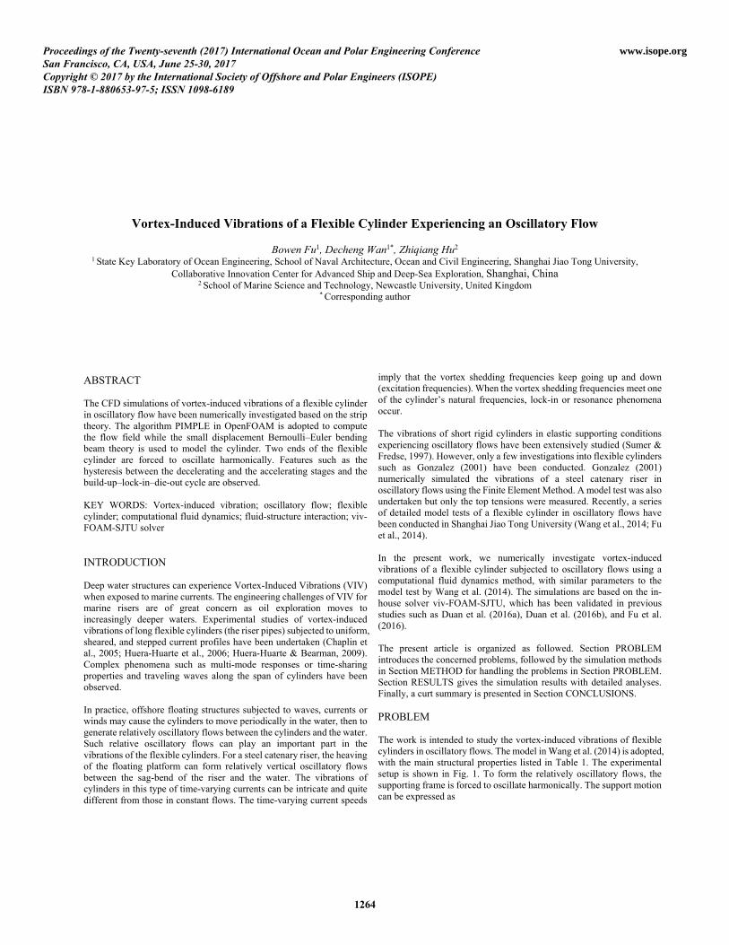
Fig. 1: Experimental setup in Wang et al. (2014). The supporting frame was forced to oscillate harmonically. In Fig. 1, the direction parallel to the forced support motion is referred as the in-line direction , while that vertical to the in-line direction and the axial direction is referred as the cross-flow direction . METHOD In order to compute the vibrations of flexible cylinders, the hydrodynamic forces acting on them must be obtained. To do this, the
transient incompressible Reynolds-averaged Navier–Stokes equations are solved numerically: 0, (6) . (7)
where is the mean strain tensor , (8) and is the Reynolds stress tensor. The SST turbulence model is employed to determining the Reynolds stresses. Table 1: Main structural properties of the flexible cylinder.
Symbols Values Units Mass ratio ∗ 1.53 Diameter 0.024 mLength 4 m Bending stiffness 10.5 N ⋅ mTop tension 500 N First natural frequency 2.68 Hz Second natural frequency 5.46 Hz To conserve the computing resources, the flow field along the long cylinder span will not be computed entirely. Instead, a strategy based on strip theory is used, with a number of two-dimensional strips located equidistantly along the span. Thus only flow fields on these strips are actually computed, while the hydrodynamic forces at other positions along the span can be interpolated accordingly. The PIMPLE algorithm in the OpenFOAM is used to compute the two-dimensional flow fields. On the other hand, the flexible cylinder is modeled as a small displacement Bernoulli–Euler bending beam, with two ends set as pinned. In the present work, the two ends of the cylinder oscillate harmonically as prescribed. It is convenient to express the beam’s total displacement in the in-line direction, referred as total in-line displacement , as the sum of the support motion , plus the relative in-line displacement (the additional displacement due to dynamic inertial and viscous force effects); i.e. . (9) The equilibrium of forces for this system can be written as , (10) where , , , are the inertial, the damping, the spring, and the hydrodynamic forces, respectively. The force components can be expressed as , , , where , , are the mass, the damping and the stiffness of the system. Thus we have , (11) . (12) In the direction vertical to the forced support motion, referred as the
1265
cross-flow direction , no additional inertial forces exist. Thus, in the finite element method the equations can be discretized as , (13) , (14) where , , and y are the relative in-line, the forced in-line, and the cross-flow nodal displacement vectors, the dot over a variable denotes its derivative with respect to time, while , , are the mass, the damping and the stiffness matrices and for the Rayleigh damping we have
, where and are from Eq. (5). and are the hydrodynamic force vectors in corresponding directions. The equations are solved using the Newmark-beta method. With both the flow fields and the structure fields being solved separately, they can then be integrated together. At the beginning of each time step the hydrodynamic forces are mapped to the structural model nodes. Then the displacements of the cylinder are computed. With the displacements obtained, the mesh can be moved or deformed, thus resulting in new flow fields from which the hydrodynamic forces can be gained. In this way, a time step is advanced. The procedure is shown in Fig. 2, based on which the solver viv-FOAM-SJTU is formed.
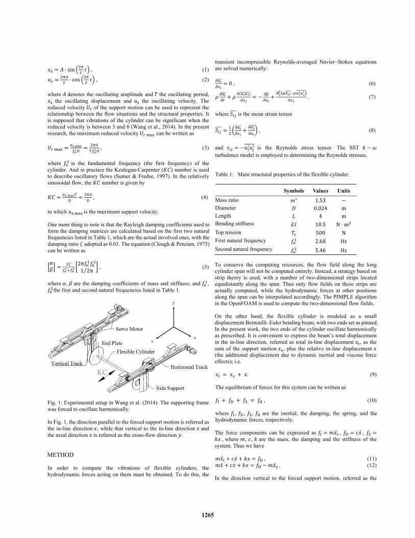
Fig. 2: Fluid-structure interaction. The fluid and the structure are coupled by hydrodynamic forces and structural deformation. Twenty strips equidistantly located along the span of the cylinder are plotted in Fig. 3. These strips share the same initial flow field mesh, as shown in Fig. 4. The motion solver “displacementLaplacian” in OpenFOAM is applied to handle the dynamic mesh (Jasak & Rusche, 2009). Imposed on the surface of the cylinder is no-slip boundary, and no external current is applied. The cylinder is discretized into 80 elements, with each element imposed of uniformly distributed loads.
Fig. 3: Twenty strips located equidistantly along the span of the flexible cylinder.
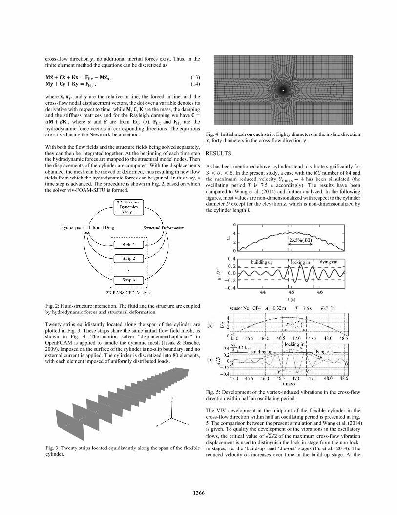
Fig. 4: Initial mesh on each strip. Eighty diameters in the in-line direction
, forty diameters in the cross-flow direction . RESULTS As has been mentioned above, cylinders tend to vibrate significantly for 3 8. In the present study, a case with the number of 84 and the maximum reduced velocity 4 has been simulated (the oscillating period is 7.5 s accordingly). The results have been compared to Wang et al. (2014) and further analyzed. In the following figures, most values are non-dimensionalized with respect to the cylinder diameter except for the elevation , which is non-dimensionalized by the cylinder length .
Fig. 5: Development of the vortex-induced vibrations in the cross-flow direction within half an oscillating period. The VIV development at the midpoint of the flexible cylinder in the cross-flow direction within half an oscillating period is presented in Fig. 5. The comparison between the present simulation and Wang et al. (2014) is given. To qualify the development of the vibrations in the oscillatory flows, the critical value of √2/2 of the maximum cross-flow vibration displacement is used to distinguish the lock-in stage from the non lock-in stages, i.e. the ‘build-up’ and ‘die-out’ stages (Fu et al., 2014). The reduced velocity increases over time in the build-up stage. At the
1266
beginning of the stage, the flexible cylinder vibrates gently in the cross-flow direction. As time passes the amplitude increases. When the amplitude exceeds the critical value mentioned above, the lock-in stage starts, during which the vibrations will reach the maximum amplitude in the half oscillating period. Similarly, when the amplitude falls below the critical velocity, the die-out stage starts and the amplitude will further decrease. It should be noted that the maximum amplitude appears not exactly at the reduced velocity peaks, but shortly after them. To qualify the build-up – lock-in – die-out cycle feature, the lock-in duration is calculated. For the selected cycle, the duration is 23.5% of the half oscillating period /2 (from 44.89 s to 45.77 s), while the value is 22% for Wang et al. (2014). From this perspective, the simulation agrees with the experiment quite well. Actually, the vibration amplitudes can vary slightly from one period to another period. To eliminate the effects of randomness and to figure out more general conclusions, more periods are studied in the following analyses. The present simulations are plotted in the upper part while Wang et al. (2014) in the lower part, with the reduced velocity of 4 and the
number of 84 (the support oscillating period of 7.5s). The actual reduced velocities of the midpoint of the cylinder are used in the present work, while that of the support motions were used for Wang et al. (2014). Oscillatory flows keep accelerating and decelerating. The typical phenomenon that the response amplitudes in decelerating stages differ from that in accelerating stages with the same reduced velocities
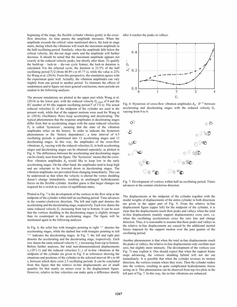
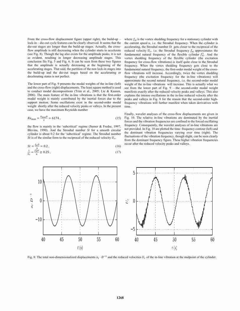
is called ‘hysteresis’, meaning that the state of the vibration amplitudes relies on the history. In order to indicate the hysteresis phenomenon or the ‘history dependence’, a time interval of 6.5 oscillating periods is partitioned into 13 accelerating stages and 13 decelerating stages. In this way, the amplitudes of the cross-flow vibrations varying with the reduced velocities in both accelerating stages and decelerating stages can be obtained separately, as plotted in Fig. 6. The differences between the accelerating and decelerating stages can be clearly seen from the figure. The ‘hysteresis’ means that the cross-flow vibration amplitudes would like to keep low in the early accelerating stages. On the other hand, the amplitudes tend to keep high and are reluctant to be lowered down in decelerating stages. The vibration amplitudes are prevented from changing immediately. This can be understood as that when the velocity is altered the vortex shedding doesn’t change immediately, resulting in unchanged hydrodynamic forces on the flexible cylinder. Another guess is that larger changes are required for a switch in a series of equilibrium states. Plotted in Fig. 7 is the development of the vortices in the flow strip at the midpoint of the cylinder within half an oscillating period. Time advances in the counter-clockwise direction. The left and right part denotes the accelerating and the decelerating stage, respectively. Each row shares the same reduced velocity increasing from top to bottom. It can be seen that the vortices shedding in the decelerating stages is slightly stronger than its counterpart in the accelerating stages. The figure will be mentioned again in the following analyses. In Fig. 6, the solid line with triangles pointing to right ‘▷’ denotes the accelerating stages, while the dashed line with triangles pointing to left ‘◁’ indicates the decelerating stages. In Fig. 7, the left and right part denotes the accelerating and the decelerating stage, respectively. Each row shares the same reduced velocity U_r increasing from top to bottom. Before further analyses, the total non-dimensionalized displacements x_t⋅D^(-1) and the reduced velocities U_r of in-line vibrations at the midpoint of the cylinder are given in Fig. 8 as references showing the situations and positions of the cylinder in the selected interval 40 s to 60 s, between which there exist 2.5 oscillating periods. It can be concluded from this figure that the relative in-line displacements are of small quantity for that nearly no noises exist in the displacement figure. However, relative in-line velocities can make quite a difference shortly
after it reaches the peaks or valleys.
Fig. 6: Hysteresis of cross-flow vibration amplitudes ⋅ between accelerating and decelerating stages with the reduced velocity varying from 0 to 4.
Fig. 7: Development of vortices within half an oscillating period. Times advances in the counter-clockwise direction. The displacements at the midpoint of the cylinder together with the modal weights of displacements of the entire cylinder in both directions are given in the upper part of Fig. 9. From the relative in-line displacement figure (upper left) for the midpoint of the cylinder, it is clear that the displacements reach their peaks and valleys when the total in-line displacements (mainly support displacements) cross zero, i.e. when the oscillating accelerations cross the zero line and change direction. Thus, it is reasonable to assume that these peaks and valleys in the relative in-line displacements are caused by the additional inertial forces imposed by the support motion over the past quarter of the oscillating period. Another phenomenon is that when the total in-line displacements reach the peaks or valleys, the relative in-line displacements only oscillate near zero, but slightly more intensely. The development of the vortices (see Fig. 7) may explain it. One should expect that when the support frame stops advancing, the vortices shedding behind will not die out immediately. It is possible that when the cylinder reverses its motion direction, the vortices remain where they were. Then the cylinder rushes into the vortices, resulting in quite complicated hydrodynamic forces acting on it. This phenomenon can be observed from top two plots in the left part of Fig. 7. In this way, the in-line vibrations are enhanced.
1267
From the cross-flow displacement figure (upper right), the build-up – lock-in – die-out cycle features can be clearly observed. It seems that the die-out stages are longer than the build-up stages. Actually, the cross-flow amplitude is still decreasing when the cylinder starts to accelerate (see Fig. 8). Though the lag also exists for the amplitude peaks, it is not as evident, resulting in longer decreasing amplitude stages. This conclusion fits Fig. 5 and Fig. 6. It can be seen from these two figures that the amplitude is actually decreasing at the beginning of the accelerating stages. That said, the partition of the non lock-in stages into the build-up and the die-out stages based on the accelerating or decelerating states is not perfect. The lower part of Fig. 9 presents the modal weights of the in-line (left) and the cross-flow (right) displacements. The least square method is used to conduct modal decompositions (Trim et al., 2005; Lie & Kaasen, 2006). The main feature of the in-line vibrations is that the first-order modal weight is mainly contributed by the inertial forces due to the support motion. Some oscillations exist in the second-order modal weight shortly after the reduced velocity peaks or valleys. In the present case, we have the maximum Reynolds number 6174, (15)
the flow is mainly in the ‘subcritical’ regime (Sumer & Fredse, 1997; Blevins, 1990). And the Strouhal number St for a smooth circular cylinder is about 0.2 for the ‘subcritical’ regime. The Strouhal number is of the similar form to the reciprocal of the reduced velocity , 0.2, (16) 0.25, (17)
where is the vortex shedding frequency for a stationary cylinder with the current speed , i.e. the Strouhal frequency. When the cylinder is accelerating, the Strouhal number gets closer to the reciprocal of the reduced velocity , i.e. the Strouhal frequency approximates the fundamental natural frequency of the flexible cylinder . And the vortex shedding frequency of the flexible cylinder (the excitation frequency for cross-flow vibrations) is itself quite close to the Strouhal frequency. When the vortex shedding frequency gets close to the fundamental natural frequency, the first-order modal weight of the cross-flow vibrations will increase. Accordingly, twice the vortex shedding frequency (the excitation frequency for the in-line vibrations) will approximate the second natural frequency, i.e. the second-order modal weight of the in-line vibrations will increase. This is actually what we see from the lower part of Fig. 9 —the second-order modal weight manifests exactly after the reduced velocity peaks and valleys. This also explains the intense oscillations in the in-line reduced velocity after the peaks and valleys in Fig. 8 for the reason that the second-order high-frequency vibrations will further manifest when taken derivatives with time. Finally, wavelet analyses of the cross-flow displacements are given in Fig. 10. The relative in-line vibrations are dominated by the inertial forces and the vibration frequencies are confined to the forced oscillating frequency. Consequently, the wavelet analyses of in-line vibrations are not provided. In Fig. 10 are plotted the time–frequency contour (left) and the dominant vibration frequencies varying over time (right). The fluctuations of the vibration frequency, though slight, can be seen clearly from the dominant frequency figure. These higher vibration frequencies occur after the reduced velocity peaks and valleys.
Fig. 8: The total non-dimensionalized displacements ⋅ and the reduced velocities of the in-line vibration at the midpoint of the cylinder.
1268
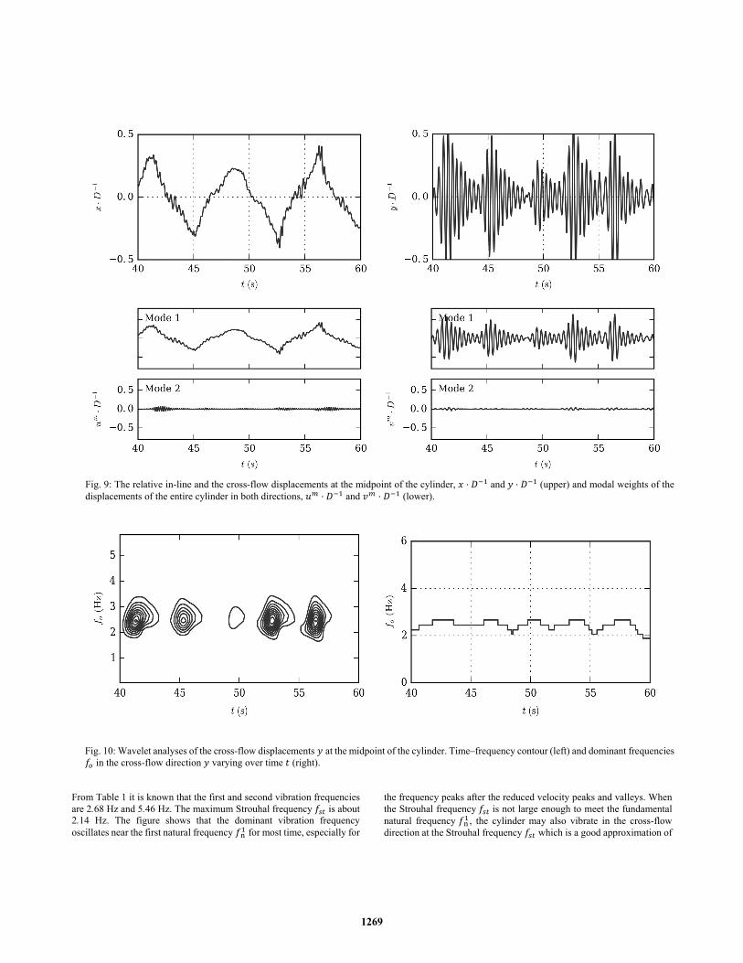
Fig. 9: The relative in-line and the cross-flow displacements at the midpoint of the cylinder, ⋅ and ⋅ (upper) and modal weights of the displacements of the entire cylinder in both directions, ⋅ and ⋅ (lower).
Fig. 10: Wavelet analyses of the cross-flow displacements at the midpoint of the cylinder. Time–frequency contour (left) and dominant frequencies in the cross-flow direction varying over time (right).
From Table 1 it is known that the first and second vibration frequencies are 2.68 Hz and 5.46 Hz. The maximum Strouhal frequency is about 2.14 Hz. The figure shows that the dominant vibration frequency oscillates near the first natural frequency for most time, especially for
the frequency peaks after the reduced velocity peaks and valleys. When the Strouhal frequency is not large enough to meet the fundamental natural frequency , the cylinder may also vibrate in the cross-flow direction at the Strouhal frequency which is a good approximation of
1269
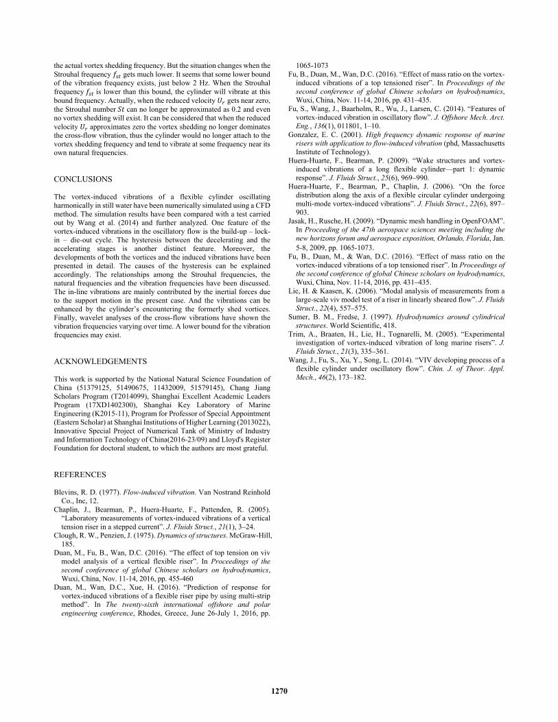
the actual vortex shedding frequency. But the situation changes when the Strouhal frequency gets much lower. It seems that some lower bound of the vibration frequency exists, just below 2 Hz. When the Strouhal frequency is lower than this bound, the cylinder will vibrate at this bound frequency. Actually, when the reduced velocity gets near zero, the Strouhal number can no longer be approximated as 0.2 and even no vortex shedding will exist. It can be considered that when the reduced velocity approximates zero the vortex shedding no longer dominates the cross-flow vibration, thus the cylinder would no longer attach to the vortex shedding frequency and tend to vibrate at some frequency near its own natural frequencies. CONCLUSIONS The vortex-induced vibrations of a flexible cylinder oscillating harmonically in still water have been numerically simulated using a CFD method. The simulation results have been compared with a test carried out by Wang et al. (2014) and further analyzed. One feature of the vortex-induced vibrations in the oscillatory flow is the build-up – lock-in – die-out cycle. The hysteresis between the decelerating and the accelerating stages is another distinct feature. Moreover, the developments of both the vortices and the induced vibrations have been presented in detail. The causes of the hysteresis can be explained accordingly. The relationships among the Strouhal frequencies, the natural frequencies and the vibration frequencies have been discussed. The in-line vibrations are mainly contributed by the inertial forces due to the support motion in the present case. And the vibrations can be enhanced by the cylinder’s encountering the formerly shed vortices. Finally, wavelet analyses of the cross-flow vibrations have shown the vibration frequencies varying over time. A lower bound for the vibration frequencies may exist. ACKNOWLEDGEMENTS This work is supported by the National Natural Science Foundation of China (51379125, 51490675, 11432009, 51579145), Chang Jiang Scholars Program (T2014099), Shanghai Excellent Academic Leaders Program (17XD1402300), Shanghai Key Laboratory of Marine Engineering (K2015-11), Program for Professor of Special Appointment (Eastern Scholar) at Shanghai Institutions of Higher Learning (2013022), Innovative Special Project of Numerical Tank of Ministry of Industry and Information Technology of China(2016-23/09) and Lloyd's Register Foundation for doctoral student, to which the authors are most grateful. REFERENCES Blevins, R. D. (1977). Flow-induced vibration. Van Nostrand Reinhold
Co., Inc, 12. Chaplin, J., Bearman, P., Huera-Huarte, F., Pattenden, R. (2005).
“Laboratory measurements of vortex-induced vibrations of a vertical tension riser in a stepped current”. J. Fluids Struct., 21(1), 3–24.
Clough, R. W., Penzien, J. (1975). Dynamics of structures. McGraw-Hill, 185.
Duan, M., Fu, B., Wan, D.C. (2016). “The effect of top tension on viv model analysis of a vertical flexible riser”. In Proceedings of the second conference of global Chinese scholars on hydrodynamics, Wuxi, China, Nov. 11-14, 2016, pp. 455-460
Duan, M., Wan, D.C., Xue, H. (2016). “Prediction of response for vortex-induced vibrations of a flexible riser pipe by using multi-strip method”. In The twenty-sixth international offshore and polar engineering conference, Rhodes, Greece, June 26-July 1, 2016, pp.
1065-1073 Fu, B., Duan, M., Wan, D.C. (2016). “Effect of mass ratio on the vortex-
induced vibrations of a top tensioned riser”. In Proceedings of the second conference of global Chinese scholars on hydrodynamics, Wuxi, China, Nov. 11-14, 2016, pp. 431–435.
Fu, S., Wang, J., Baarholm, R., Wu, J., Larsen, C. (2014). “Features of vortex-induced vibration in oscillatory flow”. J. Offshore Mech. Arct. Eng., 136(1), 011801, 1–10.
Gonzalez, E. C. (2001). High frequency dynamic response of marine risers with application to flow-induced vibration (phd, Massachusetts Institute of Technology).
Huera-Huarte, F., Bearman, P. (2009). “Wake structures and vortex-induced vibrations of a long flexible cylinder—part 1: dynamic response”. J. Fluids Struct., 25(6), 969–990.
Huera-Huarte, F., Bearman, P., Chaplin, J. (2006). “On the force distribution along the axis of a flexible circular cylinder undergoing multi-mode vortex-induced vibrations”. J. Fluids Struct., 22(6), 897– 903.
Jasak, H., Rusche, H. (2009). “Dynamic mesh handling in OpenFOAM”. In Proceeding of the 47th aerospace sciences meeting including the new horizons forum and aerospace exposition, Orlando, Florida, Jan. 5-8, 2009, pp. 1065-1073.
Fu, B., Duan, M., & Wan, D.C. (2016). “Effect of mass ratio on the vortex-induced vibrations of a top tensioned riser”. In Proceedings of the second conference of global Chinese scholars on hydrodynamics, Wuxi, China, Nov. 11-14, 2016, pp. 431–435.
Lie, H. & Kaasen, K. (2006). “Modal analysis of measurements from a large-scale viv model test of a riser in linearly sheared flow”. J. Fluids Struct., 22(4), 557–575.
Sumer, B. M., Fredse, J. (1997). Hydrodynamics around cylindrical structures. World Scientific, 418.
Trim, A., Braaten, H., Lie, H., Tognarelli, M. (2005). “Experimental investigation of vortex-induced vibration of long marine risers”. J. Fluids Struct., 21(3), 335–361.
Wang, J., Fu, S., Xu, Y., Song, L. (2014). “VIV developing process of a flexible cylinder under oscillatory flow”. Chin. J. of Theor. Appl. Mech., 46(2), 173–182.
1270