Embed Size (px)
Citation preview
Rad io ElectrorïiJc9s THE MAGAZINE FOR NEW IDEAS IN ELECTRONICS
VIDEODISC CIRCUITRY What's inside
NEW DC AUDIO AMPS Deliver ultra -wide response
PC BOARDS How to make your own
DIGITAL THERMOMETER °F and °C with 0.1° resolution
R.E.A.L. SOUND LAB Yamaha top -of- the -line receiver
SWITCHING POWER SUPPLIES How to design your own
Build this HEART RATE MONITOR
Direct readout unit
r
GAIN
o
341 !I
07
L
PLU . *HOBBY CORNER
TEMP MEASUREMENT New twist for digital clocks Clue in servicing SERVICE CLINIC AUDIO TEST STATION Beware of intermittents

It's a dgilal signal injector. And it thinks for itself.
It may look like a logic probe ... but our DP -1 Digital Pulser is E lot more unique. This handheld, circuit -powered instrument is actually a miniature pulse gererator built to speed digital troubleshooting
Tou:,--1 it to a circuit, and CP automat cally senses the logic state. So when you push the button, out comes one perfect pulse - preset to the logic fami y jouie working with - of the proper po arity to force he state the other way Hold the button down for a second and it starts injecting a
100pps pulse train. With all the punch you need -up to 100 mA.
Think wt-at a help that can be when your logic circuit is doing some- thing illogical (and just in case you do sometiing illogical, we've included reverse -polar ty and short -circuit pro- tection, as well..
It's smart to save time witi a DP -1. At $74.95`, it's a smart buy, tco.
Smarter tools for testing and design.
CONTN'ENTAL SPEaALT1ES CORPORATION
70 Fulton Terrece, New -lam. CT 06509 (203) 624 -3103, 'WX 710- 465 -1227
OTHER OFFICES San F- ancisco: (415) 421 -8872, TWX 910- 372 -7992
Europe CSC IX TD. Plooe Saffron -Walden 0'99 -21682, -LX 817477
Canada. Len F n:ler Ltc.. Ontario
Call toll -free for details 1- 800- 243- 6077 'Suggested US-resale Auailable at selected IocA distrbutors. Prices, soecific3tions sulzect to change without iotice ® 1979 Contnental Specalties Corporatior
CIRCLE 16 CSN FREE INFORMATION CARD

Don't take our word for it. "We can heartily recommend the Superboard II computer system for the beginner who
wants to get into microcomputers with a minimum of cost. Moreover, this is a `real' com- puter with full expandability."
Popular Electronics March, 1979
"(Their) new Challenger 1P weighs in at $279 and provides a remarkable amount of com- puting for this incredible price."
Kilobaud Microcomputing February, 1979
"Over the past four years we have taken delivery on over 25 computer systems. Only two have worked totally glitch free and without adjustment as they came out of the carton: The Tektronic 4051 (at $7,000 the most expensive computer we tested) and the Ohio Scientific Superboard II (at $279 the least expensive) ... The Superboard II and com- panion C1P deserve your serious consideration."
Creative Computing January, 1979
"The Superboard Il and its fully dressed companion the Challenger 1P series incorporate all the fundamental necessities of a personal computer at a very attractive price. With the expansion capabilities provided, this series becomes a very formidable competitor in the home computer area."
Interface Age April, 1979
"The graphics available permit some really dramatic effects and are relatively simple to program ... The fact that the system can be easily expanded to include a floppy means that while you are starting out with a low -cost minimal system, you don't have to throw it away when you are ready to go on to more complex computer functions. Everything is there that you need; you simply build on to what you already have. You don't have to worry about trading off existing equipment to get the system that will really do what you want it to do. At $279, Superboard II is a tough act to follow."
Radio Electronics June, 1979
"The Superboard Il is an excellent choice for the personal computer enthusiast on a
budget." Byte May, 1979
SUPERBOARD
The world's first complete computer system on a board
including full keyboard, video
display, audio cassette interface, 8K
BASIC -in -ROM and 4K RAM. Expandable.
Requires + 5V at 3 amp power supply.
Cl P MF $995.00 The first floppy disk based computer
system the world has ever seen for under $1,000. 8K BASIC -in -ROM, 12K RAM. Expandable to 32K RAM.
OHIO SCIENTIFIC 1333 S. CHILLICOTHE RD., AURORA, OHIO 44202 (216) 562 -3101
DIP $349.00 Complete with enclosure and power
supply. All features of Superboard II. Easy to expand to more memory and floppy disk.
See your Ohio Scientific dealer for full details.
CIRCLE 5 ON FREE INFORMATION CARD

ÇThATA PRECISION Model 935 DIGITAL MULTIMETER
$149 ACCURATE -
basic 0.1% DC accuracy - better than that of many
bench/lab DMM's. VERSATILE -
all the functions and ranges you need...29 in all: volts & amps, AC &
DC switchable HI & Lo ohms. ECONOMICAL -
operates up to 200 hours on a standard 9V alkaline battery.
TOUGH - built to take rough everyday field
usage and electrical overload ... yet maintain its calibration.
HANDY - easy to holld, to carry, to use,
to read ... RELIABLE -
backed by a full 2year warranty.
BASIC SPECIFICATIONS
24 Measurement Ranges: 1000V- 1000VDC, 5 ranges, ±0.1% Accuracy 1001.V- 700VAC, 5 ranges, ±0.5% Accuracy 11.4A -2A DC, 4 ranges, ±0.5% Accuracy 14A -2A AC, 4 ranges, ±0.75% Accuracy 100mß -20MQ, 6 ranges, 0.1 -0.3% Accuracy 31/2-Digit, 1/2" Liquid -Crystal Readout Automatic Polarity Indication Automatic Overload Indication Automatic Low- Battery Indication Optional Battery Eliminator Available, for 120VAC ± 10 %, 50 -60Hz line operation 6 °/ "L. x 31/2"W. x 1 Y2 "H. Weighs 11 oz. CIRCLE 69 ON FREE INFORMATION CARD
ALSO AVAILABLE - Model 938
0.1. 31/2 -digit CAPACITANCE METER, on!y $149. Ask for details.
Order Toll -Free: Call 800-223-0474
Aga ELECTRONIC
I 54 W. 45th Street, New York, N.Y. 10036, (212) 687 -2224
PLEASE SEND ME: CS11 20 -amp Current Shunt @ $20.00 Model 935 DMM @ $149.00 L] BE9 Battery Eliminator
U CC35 Vinyl Carrying Case @ $7.00 (120VAC, 50 -60Hz) @ $15.00 Payment Enclosed Bill my: Master Charge El Visa Add $3.00 to cover postage and handling. N.Y. residents add sales tax. Account # Exp. Data
Name I
Address
City, State, Zip

Radio- Electronics® THE MAGAZINE FOR NEW IDEAS IN ELECTRONICS
Electronics publishers since 1908 JULY 1979 Vol. 50 No. 7
BUILD ONE 35 Heart Rate Monitor Provides a direct readout of your pulse rate in beats -per- minute. by Mark C. Worley
42 Digital Thermometer With a 3'/: -digit LED display this device measures temperature in
Celsius and Fahrenheit to 0.1 degree resolution. By Bill Owen
54 Audio Test Station Concluding article provides the step -by -step calibration procedures. by Ray Davison
VIDEO 39 Videodisc -A Look At The Circuitry Part 2- What's inside the new videodisc players by Larry Steckler
74 Service Clinic Intermittents can cause strange symptoms by Jack Darr
74 Service Questions R -E's Service Editor solves technician problems.
AUDIO 47 DC Amplifiers New audio amplifier circuitry provides ultra -wide frequency response. by Len Feldman
50 R.E.A.L Sound Lab Tests Yamaha CR -2040 Receiver Top -of- the -line receiver rates excellent
TECHNOLOGY 4 Looking Ahead Tomorrow's news today by Dave Lachenbruch
58 Make Your Own PC Boards A look at the tools and techniques. by James Temple
61 Switching Power Supplies How to design your own by L. Steven Cheairs
64 Secret Weapon Against Tough Dogs Temperature measurement helps localize faults by Henk Onstee and Stu Rauch
66 Hobby Corner Modification for digital clocks provide long delay alarm. by Earl "Doc" Savage, K4SDS
68 State -Of -Solid -State New A/D converter fast enough to digitize video signals by Karl Savon
EQUIPMENT 24 Graymark Model 540 Binary Clock
25 BSR System X10 AC Remote Control
26 RCA COSMAC Evaluation Kit
DEPARTMENTS 112 Advertising Index
76 Computer Products 6 Editorial
113 Free Information Card
12 Letters
90 Market Center 88 New Literature 78 New Products 85 Stereo Products
ON THE COVER Using an infrared sensor that clips to your finger, this Heart Rate Monitor provides a direct readout of your pulse rate in
beats -per- minute. It also "beeps" to provide an audible indication. Sounds interesting? Read about it starting on page 35.
R R
n r
P T
QS
HEART WAVEFORM is detected by Heart Rate Monitor circuit to provide a direct readout in beats -per- minute. To see how it works, turn to page 35.
COMPLEX WAVEFORMS are needed to com- pare the performance of DC amplifiers. To find out why, turn to page 47.
Radio -Electronics, Published monthly by Gernsback Publications, Inc., 200 Park Avenue South, New York, NY 10003. Phone: 212- 777 -6400. Controlled Circulation Postage Paid at Concord., NH. One -year subscription rate: U.S.A. and U.S. possessions, $9.98, Canada, $12.98. Other countries, $14.98. Single copies $1.25. © 1979 by Gernsback Publications, Inc. All rights reserved. Printed in U.S.A. (ISSN 0033 -7862)
Subscription Service: Mail all subscription orders, changes, correspondence and Postmaster Notices of undelivered copies (Form 3579) to Radio -Electronics Subscription Service, Box 2520, Boulder, CO 80322.
A stamped self- addressed envelope must accompany all submitted manuscripts and /or artwork or photographs if
their return is desired should they be rejected. We disclaim any responsibility for the loss or damage of manuscripts and /or artwork or photographs while in our possession or otherwise.
As a service to readers, Radio- Electronics publishes available plans or information relating to newsworthy products, techniques and scientific and technological developments.
Because of possible variances in the quality and condition of materials and workmanship used by readers, Radio -Electronics disclaims any responsibility for the safe and proper
functioning of reader -built projects based upon or from plans or information published in this magazine.
3
Awl*: leaf
Videodisc jockeying: With one videodisc system on the market in limited quantities (Philips /MCA /Magnavision) and one promised for late 1980 or 1981, it would appear that there would be little room for additional systems. Although many different systems have been demonstrated in the past, it has been tacitly acknowledged that Philips and RCA would fight it out between themselves for the upcoming videodisc market. Of course, this left the Japanese without an entry in videodiscs, but because of their preoccupation with videotape at the present time, some knowledgeable industry sources assumed the Ja- panese would sit this one out and, when the proper time came, adopt either the Philips (optical) or the RCA (capaci- tance) system. But Japan's biggest consumer electronics manufacturer, Matsushita, apparently feels the stakes are too high to wait passively. Matsushita's earlier videodisc system, called "Visc," could easily have been brought into compatibility with RCA's capacitance system, and most observers thought it would be.
It was surprising, therefore, when, at a very late stage in the game, Matsushita introduced a new videodisc system and pointedly said it was ready for production. The new "Visc -O -Pac" is a variable -speed disc that can store at least two hours on two sides of a 9- inch -diameter record. The speed varies from 300 rpm at the outside of the disc to 700 near the center. Like the original Visc, the new system uses grooved discs and reads them out mechanically with a
"twist stylus" that translates the discs's hills and dales to variations in torque. The new disc is packed in a transpar- ent case that is automatically removed when the record is played and restored when playing is complete. RCA's SelectaVision discs are 12 inches in diameter and revolve at a constant 450 rpm. Each one is packed in a plastic caddy, which is slid into the changer and pulled out.
An RCA spokesman says SelectaVision's design is "fro- zen" and won't be changed to compromise with the new Matsushita system. If Matsushita really intends to introduce a third "standard," it could have a rough road since both RCA and MCA have been lining up programming for the capacitance and optical systems, respectively, and Matsu- shita would appear to be well behind in this activity. Matshushita would be a formidable ally for either propo- nent, and both the Philips /MCA and RCA camps are trying to determine whether it really will seriously pursue a third system or whether Matshushita is using Visc -O -Pac to improve its bargaining position or is trying to delay the videodisc market to avoid cutting into the videocassette boom.
Eight shows, one channel: Borrowing liberally from other people's inventions, RCA Americom, which operates Satcom satellites, is proposing a new transmission system to the Armed Forces Radio & Television Service that will make possible simultaneous reception of TV shows. AFRTS, which operates about 150 TV stations at U.S. mili- tary bases on foreign soil, currently does most of its programming by videocassettes shipped from the U.S. RCA proposes to supply two TV channels, five full 15 -kHz
audio channels and an on- screen teletext channel, carrying them all on a single satellite channel. They would be beamed directly via Satcom to U.S. bases in the Western Hemisphere and relayed to Intelsat to serve U.S. troops elsewhere.
The two -channels -in -one are derived from an invention by CBS and Thomson -CSF called STRAP, or Vidiplex, which interweaves two separate TV pictures using alternate fields of each picture. The missing fields are reconstructed at the receiving end from information contained in adjacent fields. Four of the five audio channels are digitally encoded into the television picture by a process called DATE (digital audio for TV) developed by the Public Broadcasting System. The teletext channel is carried in the TV signal's vertical interval.
Pocket `brains': The successor to the pocket calculator almost certainly will be the hand -held memory or micro- computer or whatever you want to call it -it's so new there's no generic name for it yet. The trend started with the pocket "memo pad" that could store about 30 phone numbers or whatever you wanted to store in it. Now memo- ries have been sharply expanded, and two hand -held "lan- guage translators" have come on the market at almost exactly the same time. Called the Lexicon and the Craig M100, they are made by different companies but both are presumably based on the same Mostek IC. They both sell in the $200 range and contain alphanumeric keyboards, doing double duty as calculators and metric converters.
Although there are differences between the two, let's discuss the Craig as probably "typical" of this new type of device. Initially, finger -sized program cartridges are avail- able for English, French, German, Spanish and Japanese. Three cartridges can be loaded into the battery- operated unit at one time, and translations can be made from any one to any other. Each cartridge has a "vocabulary" of 1,500 words or phrases. In addition, 50 commonly used phrases are listed on the back of the translator, with a code number for each. You just type the code number on the translator and the foreign equivalent appears on the fluo- rescent display that holds up to 16 letters but can accom- modate more with a right -to -left crawl similar to that on a movie theater marquee display. Any of 1,500 words may be entered on the keyboard for translation to any language whose cartridge is inserted in the machine. In addition, the unit helps correct spelling, works as a language quiz machine and fulfills other language -learning functions.
While the first generation of these machines helps accomplish the obviously important function of language translation, future cartridges will fulfill other needs. Recipe storage, dictionary synonyms and calorie counting come to mind immediately -and undoubtedly there will be more. According to Craig, a near -future generation of the ma- chine will be programmable, making it an important device for storage of personal information.
DAVID LACHENBRUCH CONTRIBUTING EDITOR

LOW TIM MAKES THE LISTENING DIFFERENT.
COMPARABLE AMPLIFIERS DO SOUND DIFFERENT
Choosing the best amplifier for your audio system involves comparing specs, features and, of course, price. But ultimately, if you love music, you should base your decision on the way an amplifier sounds when reproducing music.
Two amplifiers may have identical power ratings and virtually no Total Harmonic Distortion, but can sound very different: one clean and clear, the other harsh and metallic. The difference you hear is
Transient Intermodulation Distortion (TIM, for short). The real effects of TIM on music, however, have only recently been recognized, since TIM does not show up in even the most accurate traditional laboratory measurements.
Measurements for THD are made with smooth, repetitive signals (sine waves). Music, on the other hand, presents an amplifier with a series of non -repeating, pulsive, "transient" signals, as illus- trated below. !11 /11111k1111111111111110111111111111
1111Irr,11II\r111 Mr11r/ NAtif 7/,1 I/rIl/1
All /t I e.11111
I ria 11Ir1:f MIRA i111il i I r SINE WAVES DYNAMIC MUSIC SIGNALS
An amplifier that cannot faithfully follow the sharp transients demanded by music may have very low THD, but very high TIM.
WHAT CAUSES TIM? It has been discovered that TIM distortion in
an amplifier is caused by an insufficient slew rate - the engineer's term for an amplifier's ability to handle the high power, high frequency signals a musical transient presents. Poor slew rate in conventional amplifiers is most often caused by the very mech- anism used to reduce THD, namely, the addition of negative feedback. Put more simply, in convention- ally- designed power amplifiers, the more negative feedback you use, the lower will be the THD (which is
good), but the higher will be the TIM (which is
not so good). It took Sansui, and a whole new approach
to amplifier design, to solve the high- frequency slew - rate problems of TIM without compromising our superbly low THD specifications.
THE SANSUI SOLUTION The most important step in the solution was to
"speed up" (increase the frequency response of) the basic amplifier - even before negative feedback is applied - by using Sansui's own patent -pending DD/ DC (Diamond Differential/Direct-Coupled)
CIRCLE 68 ON FREE INFORMATION CARD
AU -919 DD /DC AMPLIFIER
circuit. The DD /DC circuitry includes a sophisti- cated "lag + lag- lead" dual compensation sys-
tem, more often found in instrumentation amplifiers than hi -fi products, which maintains stability without decreasing frequency response. With DD /DC, the amplifier can instantly supply the enormous negative feedback current demanded by transients, without restricting the slew rate, so without introducing TIM.
How well our unique circuitry suc- ceeds in eliminating TIM, while maintaining extraordinarily -low levels of THD is shown in these comparative curves. The Sansui AU -919 amplifier (bottom curve) is rat- ed at 110 watts per channel, min. RMS, both channels into 8
ohms from 10Hz to 20,000Hz, with no more than 0.008% total harmonic distortion. Power output vs. TIM distortion curves for the Sansui AU -919 and competitive amplifiers. Derived using the TIM mea- surement method described In a paper presented at the 63rd Convention of the AES May,1979; available from Sansui on request.
POWE /TIM DISTORTION
AMP A
3 4 5 Io ,O3
LET YOUR EARS BE THE JUDGE Instruments and circuit -design analysis are
fine in their place, which is the laboratory. But you listen to music in your home; and we're confident that you will hear the difference in musical clarity that a Sansui amplifier makes. Your local Sansui authorized dealer can demonstrate all the convincing reasons for choosing Sansui.
SANSUI ELECTRONICS CORP Lyndhurst, New Jersey 07071 Gardena, Ca. 90247 Sansui Electric Co., Ltd., Tokyo, Japan Sansui Audio Europe S.A., Antwerp, Belgium In Canada. Electronic Distributors
SQruz«
ediiorial
A Call For New Ideas Every magazine has an editorial policy. It provides the guidance that
determines the subject matter that is covered on a monthly basis. The editorial policy of Radio -Electronics is quite basic. We sum it
up in one sentence and place it on the front cover each and every month, right below our logo. It reads: "The Magazine for New Ideas in Electronics."
Simple? Sure, but oh how difficult to achieve. It means that we maintain contact with the engineering departments of the semiconductor houses, research labs, key manufacturers as well as various industry sources. We go right to the source, then sift out the best ideas and present them in the best way we know how, either as an application note, a construction or tutorial article, etc.
Certainly a percentage of the new ideas come from you, our reader. But the percentage is small. Too small. This could be interpreted to mean that our readers are basically idealess. This is surprising, as it has been our contention for many years that you, our reader, the electronics activist, are a vast untapped reservoir of new ideas. Why then, haven't we seen more of your ideas? We feel that the problem comes down to the fact that it is just too much of a pain to write an article about the ideas that you have. Let's face it; writing a three- or four -page article is downright difficult.
We now think we've found a solution. It's a new column and you guessed it, it's called New Ideas. It will consist of just about anything innovative. It could be a new circuit, IC application, gadget, or even an innovative use for a new component, a new way to hook up your test equipment, or a new or faster way to lay out or etch your PC boards.
Submitting your idea is easy, but it must include an illustration. If it is a new application of a component or a better circuit approach to something that has already been done, include a schematic or a pictorial drawing. You can draw it freehand, but be sure that it is legible. If we use it we'll have it redrawn by our illustrators. Otherwise, a photograph (black and white and in focus, please) will suffice.
The written description is also a lot easier than a full -length article; a maximum of four and a minimum of two typewritten pages, double- spaced. The first paragraph should describe your New Idea. Next, explain why it is innovative. The rest of the text should be a detailed explanation that includes any necessary information your fellow readers will need to be able to actually use it. Keep the words simple.
Submitting the idea is a matter of snipping out the coupon, filling it out, signing it and mailing it with your idea to us. The coupon contains some legal copyright jargon which gives us your permission to publish it. If we don't publish it we'll return all of the material to you.
If we do publish your New Idea, you'll see your name in print and we'll send you a check for $25. So now what's your excuse? We know you have the ideas. Get up off your . . er . . . laurels and write them up.
ART KLEIMAN Managing Editor
Radio-Electronics® Hugo Gernsback (1884 -1967) founder M. Harvey Gernsback, editor -in -chief and
publisher
Larry Steckler, KTX -3644, CET, editor Arthur Kleiman, KTZ -3288,
managing editor Robert F. Scott, CET, W2PWG,
KXK -8533, technical editor Sonia Greenbaum, copy editor
Jack Darr, CET service editor Leonard Feldman
contributing high -fidelity editor Karl Savon, semiconductor editor Herb Freidman, communications editor David Lachenbruch, contributing editor Earl "Doc" Savage, K4SDS, hobby editor Ruby Yee, production manager
Robert A. W. Lowndes, production associate
Marie J. Stolti, production assistant
Harriet I. Matysko, circulation director Arline R. Bailey, advertising coordinator
Cover design by Louis G. Rubsamen Cover photo by Mel Small
Radio Electronics is a member of the Insti- tute of High Fidelity and is indexed in Applied Science & Technology Index and Readers Guide to Periodical Literature.
NEW IDEAS All published entries will earn $25 upon publication. Selections will be made at the sole discretion of the editorial staff of Radio -Electronics.
I agree to the above terms and grant Radio -Electronics Magazine the right to publish my idea. I declare that the attached idea is my own original materi- al and that its publication does not violate any other copyright. I also de- clare that this material had not been previously published.
Title of Idea
Signature
Print Name Date
Street
City State ZIP
Mail your idea along with this coupon to:
New Ideas Radio -Electronics 200 Park Ave. South New York, NY 10003
YI

We confess. To sell an advanced DMM for under $70 we had to cut corners. And we sure did! First, we cut off the dealer's markup. Then we shaved off the overhead costs of national sales offices and warehouses. Finally, as if that wasn't enough, we even cut out the high labor costs of factory assembly lines. All in all, we cut over $100 worth of corners! But not a single one that affected the quality and performance of our new DMM.
Don't let our low price fool you! Because Sabtronics sells factory -direct - without all the hidden charges a dealer would track on - we can offer the superior 2010A DMM kit for a surprisingly low $69.95. Surprising because you get the accuracy, features and performance you'd expect from the high priced units.
The 2010A offers you the long -term accuracy of a laser -trimmed resistor network, an ultra - stable band -gap reference element and single chip LSI circuitry - all in a compact, rugged, human- engineered housing. With 31 ranges and 6 functions, you can measure AC and DC volts from 100 µV to 1000V; AC and DC current from 0.1 µA to a surprisingly high 10A; resistance from 0.10 to 20 MD. Typical DCV and Ohms accuracy is 0.1% ±1 digit. And you see these precise readings on a bright, 31/2-digit
Brief Specifications DC Volts: 100µV to 1000V in 5 ranges AC Vohs: 100µV to 1000V in 5 ranges DC Current: 0.11,A to 10 Ain 6 ranges AC Current: 0.1µA to 10 A in 6 ranges
Resistance: 0.10 to 20 MO in 6 ranges
Diode Test Current: 0.1µA, 1001, 1 mA
ACV Frequency Response: 40Hz to 40kHz
Input Impedance: 10 MO on ACV and DCV
Overload Protection: 1200 VDC or RMS on ail voltage ranges except 250 VDC or RMS on 200mV and 2V AC ranges. Fuse protected on ohms and mA ranges.
Power Requirement: 4.5 to 6.5 VDC (4 "C" cells) optional NiCd batteries or AC adapter /charger Display: 0.36" (9.2mm) Digits reading to ± 1999
Size: 8 "W x 6.5 "D x 3"H (203 x 165 x 76 mm)
Weight: 1.5 lbs. (0.68kg.) excl. battery
LED display with automatic decimal placement and large, 9mm numerals.
Of course, that's what you'd expect from a
quality DMM. But we've even added more features for extra convenience, flexibility and reduction of human error.
Unique Xl0 Multiplier Switch - gives you convenient push -button selection to the next higher decade range. Hi -Lo Power Ohms capability gives you three high -ohms ranges that supply enough voltage to turn on a
silicon junction for diode and transistor testing. For in- circuit resistance measurement without turning on a semiconductor junction, you use the three low -ohms ranges.
Wide Frenquency Response - 40Hz to 40kHz bandwidth lets you measure audio through ultra -sonic AC signals.
Touch and Hold Capability - with optional probe, retains readings for as long as you wish. You can make measurements in hard-
to -reach places without taking your eyes off the probe tip or stopping to record data.
Plus More - Auto Polarity, Auto Zero, Overrange indication and fully overload protected on all ranges.
And, although designed for benchtop use, the sleek, compact 2010A is powered by 4 "C" cells (not induded), bringing wide -range lab performance to the field when you need it.
You save either way. Your 2010A DMM kit comes complete with easy -to- follow assembly instructions, all parts (including high -impact case), and test leads. You can complete assembly in a single evening. However, for a slight additional fee, Sabtronics will ship your 2010A factory -assembled and calibrated: at $99.50 it's still an incomparable value! Whether you're a professional or hobbyist, if quality and accuracy are important - and padded prices aren't - you should inspect the 2010A DMM for yourself. If you're not completely satisfied, return it in its original condition within 10 days for a prompt and courteous refund of purchase price. Call us with your MasterCharge or Visa order today, or simply fill out the convenient order form.
Making Performance Affordable
sabtronics IN 1 E RNAT IONAL INC.
13426 Floyd Circle M/S 35 Dallas, Texas 75243 Telephone 214/783-0994
To: Sabtronics International, Inc. 13426 Floyd Circle M/S 35, Dallas, TX 75243 Please send me .
2010A Digital Multimeter kit(s) @569.95 plus $4.00} shipping and handling each $
Model 2010A Digital Multimeter Assembled @ $99.50 plus $4.001 shipping and handling each $
ix AC -115 AC adapter /charger(s) @$7.50 each S
x NB -120 NiCd Battery set(s) @517.00 /set S
THP -20 Touch and Hold Probe(s) @S18.00 each S
For delivery in Texas, add 5% Sales Tax 5
I enclose O check money order for . . . . TOTAL S
or, please charge to my Visa MasterCharge: Code u Account No Expiration Date:
Name
Street Apt
City State Zip
L'Continental U S. only. AK, Hl 8 PR. 55.00, Canada:$6 50. Foreign: 519.00 Airmail

Everybody's making money selling microcomputers.
Somebody s going to make money servicing them.
New NRI Home Study Course Shows You How to Make Money Servicing, Repairing, and Programming Personal and Small Business Computers

Seems like every time you turn around, somebody comes along with a new
computer for home or business use.
And what's made it all possible is the
amazing microprocessor, the tiny little
chip that's a computer in itself.
Using this new technology, the
industry is offering compact, affordable
computers that will handle things like
payrolls, billing, inventory, and other
jobs for businesses of every size...per-
form household functions including
budgeting, environmental systems
control, indexing recipes, and more.
And thousands of hobbyists are already
owners, experimenting and developing
their own programs.
Growing Demand for Computer Tlechnicians
This is only one of the growth
factors influencing the increasing
opportunities for qualified computer technicians. The U.S. Department of
Labor projects over a 100% increase in
job openings for the decade through
1985. Most of them new jobs created by
the expanding world of the computer.
Learn at Home in Your Spare Time
NRI can train you
for this exciting, rewarding field. Train you at home to service not only micro- computers, but their larger
brothers, too. Train you at your convenience, with clearly written "bite- size"
lessons that you do evenings
or weekends, without going to classes
or quitting your present job.
Assemble Your Own Microcomputer
NRI training goes far beyond
theory. It includes practical experience, too.
As you progress, you perform meaningful
experiments building and studying elec-
tronic circuits on the NRI Discovery Lab ' You assemble test instruments that in-
clude a transistorized volt -ohm meter and a CMOS digital frequency counter... instru-
ments you learn on, use later in your work.
And you build your own microcomputer.
Each step of construction advances your
knowledge, gives you deeper insights
into this amazing world that's upon us.
This is the only microcomputer de-
signed for learning. It looks, operates, and
performs just like the finest of its kind...ac-
tually does more than many commercial
units. But NRI engineers have designed
components and planned the assembly
procedure so it demonstrates important principles, gives you working experience
in detecting and correcting problems.
And that's what NRI
training is all
about.
Other Opportunities in Electronics
Since 1914, before commercial radio
was even on the air, NRI has been the way
to learn new electronics skills. Tbday's
modem offerings include, in addition to
three different computer courses, TV /Au-
dio/Video Systems Servicing, with training on the only designed -for -learning 25"
diagonal color TV, with state -of- the -art computer programming. Or, check out
our Complete Communications Course,
preparing you to enter this booming field servicing, installing, and repairing
equipment like microwave, broadcast, CB,
shortwave radio, paging, radar, and more.
Mail Postage -Paid Card for Free Catalog
No Salesman Will Call Send today for your free copy of our
100 -page, full -color catalog. It describes all
of our electronics courses in detail, show-
ing kits, equipment, and lesson plans.
Look it over at your convenience, then
decide how NRI can help you make the
most of your talents. There's no obligation
and no salesman will ever call or bother
you. With more than a million students
and unmatched experience in home train- ing, NRI gives you the most in training for new opportunity! If card has been
removed, write to:
NRI tlI NRI Schools McGraw -Hill Continuing
Education Center
3939 Wisconsin Avenue Washington, D.C. 20016

SOLVING THE ENERGY CRISIS? It seems to me that the big challenge for
electronics in the immediate future is- energy. So, here's an impossible idea:
High school physics taught us that mat- ter and energy are interchangeable. More to the point, one gram of matter is inter- changeable with an enormous quantity of energy . . . in other words, if you could convert one gram of matter into energy with 100% efficiency you could light up New York for a year.
For practical purposes, 100% conversion does not exist. The most efficient conver- sion process to date (atomic reaction) involves huge quantities of energy from very little fuel. The problem, then, is to come up with a way to produce a technique of matter -to- energy conversion which is almost completely efficient, controllable and suitable for use with abundant and cheap materials.
We have all learned that matter must occupy volume. Clearly then, it must be- come something other than matter, and all
that is left is energy. Therefore, let's postu- late that if you squeeze something hard enough it will interchange its volume for an equivalent quantity of energy.
The problem lies in squeezing hard enough. You obviously also don't want to squeeze too much matter at a time or the energy produced becomes difficult to con- trol. Therefore, perhaps sufficient pressure could be obtained by two rapidly moving, very small particles colliding with each oth- er.
The machinery necessary to do this could be based on the particle accelerator, a device that uses switched magnetic fields to accelerate atomic particles. The device could be toroidal, but a linear setup would be more practical since it would not involve changing the direction of the particles we wish to impact. In other words, build a junior -sized atom smasher.
It would be shaped as a tube several miles long so that it can achieve the veloci- ties required for the densities being used. It will be airtight because you want to evacu-
ate the atmosphere from inside it so that the rapidly moving particle will not encoun- ter friction from the gas molecules and incinerate itself. Induction coils will be spaced out along the length of the tube; their magnetic fields will move the matter around. Also used will be sensing coils and some deflection coils (their function will be described later on).
To derive the flux densities required to do the job, some heavy currents will have to flow through the induction coils. To do this without generating excessive heat, the coil resistance must be negligible. The tube must be encased in a jacket inside which a supercoolant can be injected.
At the terminal end of the accelerator will be a structure containing a black- bodied oven, the walls of which contain pipes through which water or some other heat - exchanging liquid can pass to extract the heat of the impact and remove it so it can be converted to electricity. Beyond the oven structure is a second accelerator
continued on page /4
Another reason to join RCA's QT Parts Program! You get four free information packages every year.
RCA's QT -150 Parts Program is better than ever! Registered dealers receive four free
information mailings per year through RCA's Direct Information Service program.
Quarterly mailings include: Complete Dealer Price Book - RCA Consumer
Parts Latest Price Supplement RCA Drawing Number to Stock Number Cross
Reference Color TV Module Cross Reference B &W TV Module Cross Reference
Dealer QT Inventory Control Form; and many other useful publications.
To join, contact your RCA Distributor and register as a QT Dealer. You will receive
your package of 150 of the most -needed, fastest -moving parts to repair older TV sets.
You will also receive your first quarterly information package. Every information
mailing will include the latest price publication, plus additional infor-
mation about RCA Parts required in your servicing business.
Don't forget, your QT Parts inventory program has automated annual drop -ship updating for your convenience. A special
QT Parts Rack is also available to save time and space.
Call your RCA Distributor or write to RCA Distributor and Special Products Division,
Deptford, N.J. 08096.
RCA,. QT Parts

ANNOUNCING AMERICA'S ONLY
LAND, SEA AND AIR SCANNER.
Only the incredible, new, no- crystal Bearcat 220 Scanner tunes in all the real excitement of the entire AM aircraft band-plus every FM public service frequency -with pu button ease.
Now. Tune in all the real excitement of the wild blue yonder, at the touch of a button.
The new, no- crystal Bearcat 220 Scanner searches and tunes in the entire air- craft band. Jets at 30,000 feet. All the tense tower talk. Everything is pre -programmed in space -age memory banks.
Only the 7 -band Bearcat 220 Scanner also brings home every public service frequency, too. Pre -programmed Marine frequencies. Police ac- tion. Fire calls. Weather warnings. You name it.
The new Bearcat 220 has all the features and quality Bearcat Scanners are famous for. Track tuning. Decimal display readout. Automatic Search. Selective Scan Display. Automatic squelch and lockout. Priority. And much, much more.
After all, Bearcat invented Scanning. And we'll stop at nothing to bring you all the excitement - of land, sea, and air.
BEARCAT Z10 SCANNER
rl.. Follow the leader to real excitement.
ueC ¿e. Copyright 1979 Electra Company Division of Masco Corp. of Indiana 300 East Courty Line Road. Cumberland. Inciana 46229 p CD
CIRCLE 54 ON FREE INFORMATION CARD 13

LETTERS continued from page 12
tube, the mirror image of the first. Here's the procedure: Place a particle of
matter at each end of the tube, suck out all the air and cool everything down with liquid nitrogen, helium or some other coolant. Switch the power on and off for each of the inductance coils in sequence so as to cause the particles to accelerate toward each other. They enter the black- bodied oven via two small ports and collide. If the accelera- tion is sufficient to produce the required pressure to cause the particles to become greater than their greatest possible density (to interchange themselves with energy) what results is a very small, very hot ball of
raw power. Those elements that can radi- ate through a vacuum (i.e., light) will do so and will be converted to heat upon reach- ing the oven. The rest will be contained in the ball. It can then be tapped by allowing a measured air pressure into the oven. The heat can be used to produce steam.
Now, here come the electronics. We need a humdinger of a real fast computer to determine when the coils are to be switched on and off, or the particles will not accelerate sufficiently. It must also keep both particles in the dead center of the tubes or they won't intercept each other. To do this, it will have to sense the position of the particle and adjust it with the deflec- tion yokes. Furthermore, the computer will have to adjust for any differences in the relative velocities of the two approaching
Sharp Enough To Cut A Human Hair...
Tough Enough To Cut Piano Wire
A precision cutting tool with muscle to match. Perfectly mated cutting edges, hand honed, sci- entifically hardened. Jaw -opener coiled spring, a great help on repetitive jobs. Drop forged, fine polished, top quality steel. Blue dipped plastic comfort grips. In brief, the extras that reward you for insisting on hand tools by CHANNELLOCK.
CHANNELLOCK, INC., Meadville, Pa. 16335
Send For Our Free Catalog
No. 436 GS Diagonal Cutter
CIRCLE 8 ON FREE INFORMATION CARD
particles, so that they collide dead center in the black -bodied oven. Perhaps the logic of this computer could be created with LSI tunnel diodes because tunnel diodes can switch very fast and the LSI techniques can reduce the distances the pulse must travel, and thus the delay.
You'll also need a new semiconductor device -a mega -thyristor, perhaps -that can switch thousands of amps at thou- sands of volts extremely quickly. Printed circuit boards for the control circuitry will be available shortly (!); check your local dealers for a few miles of surplus reinforced 9 -inch glass pipe and a couple of hundred gallons of liquid helium. The coils can be hand -wound with No. 000 magnet wire. STEVE RIMMER Markham, Canada
TUNER TEST COMPARISONS The June 1978 issue of Radio- Electron-
ics contained a test on the Luxman model R -1120 receiver. The same model was tested by Stereo Review (another reputa- ble hi -fi magazine). The results were pub- lished in Stereo RevieWs September 1978 issue. However, the results between the two tests were quite different in some respects.
The greatest difference appeared in the channel separation readings of the tuner section. According to Radio -Electronics' stereo performance measurements, the channel separation at 100 Hz was a very high 60 dB (superb), while Hirsch -Houck Labs obtained only something like 42 dB up to 500 Hz. Furthermore, their descrip- tion of the channel separation vs. frequen- cy makes me think that they have been testing a downright different receiver.
Also, there is a difference (I am not saying error) between their readings of the harmonic distortion of the amplifier sec- tion. At 1 watt and 1 kHz, Radio- Electron- ics gives 0.03 %, while Hirsch -Houck Labs offer only 0.01 %. As someone who works in this field, it is hard for me to believe that the results of these two tests represent both extremes of the performance tolerances of this particular Luxman receiver. If this is so (in spite of my disbelief), there is no point in claiming channel separation or anything else with an accuracy of decibels (some- times even tenths of dB's). The same applies to all measurements. A more obvi- ous reason why Hirsch -Houck Labs re- ceived lower separation readings is that the stereo decoder adjustments were not tuned to their optimum, as they were in the unit tested by Radio -Electronics.
You may have noted that, in bringing up the issue of the discrepancies between test results published by the two magazines, I
have based everything on the fact that both tests are completely valid. Should a test report reveal the very best readings or the worst? Or something in between? Which would be most useful to the consumer who is thinking of buying the Luxman model R -1120 since the particular unit he gets can have a low- frequency channel separation anywhere between (or outside of) 42 dB and 60 dB?
I don't know which one of the two tests was made first, but Radio -Electronics published its results in the June issue, whereas Stereo Review included its report in the September issue, thereby being the
continued on page 16

WHY CUT? WHY STRIP ? WHY SLIT ?
WHY NOT...
JUST
JUST WRAP TOOL WITH ONE! 50 FT. ROLL OF WIRE
COLOR PART NO. U.S. LIST PRICE
BLUE JW'11B $14.95 WHITE JW -1W 14.95 YELLOW JW -1 -Y 14.95 RED JW.1.R 14.95
REPLACEMENT ROLL OF WIRE 50 FT.
BLUE R -JW.B 2.98 WHITE R-JIWW 2.98 YELLOW R-JW.Y 2.98 RED R -J'WR 2.98
AWG 30 Wire .025" Square Posts Daisy Chain or Point To Point No Stripping or Slitting Required ....JUST WRAP TM....
Built In Cut Off
$ 95 Easy Loading of Wire Available Wire Colors :, Blue, White, Red & Yellow
USA. FOREIGN
PATENTS
PENDING
DAISY CHAIN POINT TO POINT
OK MACHINE & TOOL CORPORATION 3455 CONNER ST., BRONX, N.Y. 10475 (212) 994 -6600 /TELEX 125091
MINIMUM BILLING $25.001 ADD SHIPPING CHARGE $2.001 NEW YORK CITY I STATE RESIDENTS ADD APPLICABLE TAX.
CIRCLE 32 ON FREE INFORMATION CARD

LETTERS continued from page 14
later of the two. Anyway, I think that Stereo Review failed to give the correct informa- tion by publishing the test results of the receiver, the tuner circuits of which were not correctly adjusted. Radio -Electronics published its results several months earlier, from which Stereo Review could have no- ticed there was something wrong with its test results. Nobody has commented on this matter -neither the readers nor the magazine's editorial staff to date.
Returning to the question of what is best and most useful for the consumer, it is clear that such a discrepancy between the tests of the same product is nothing but confus-
ing. Anyone can find a somewhat similar case by comparing the test reports of the Harman /Kardon Citation 16, published in both magazines.
The problems associated with modern FM tuner measurements are not unknown to me. The quality of tuners seems to outperform their test equipment to a great- er and greater extent. One such aspect is the measurement of the channel separa- tion. I assume that in both tests, the Sound Technology model 1000A stereo signal generator was used for the channel -sepa- ration measurement. This fine equipment, however, is claimed to give a separation of 50 dB from 50 Hz to 8 kHz, so a separation of 60 dB at 100 Hz achieved by the Luxman model R -1120 receiver should be very near the limit of the test signal itself.
THE BENCH -TYPE DMM'S, FROM SOAR ...THEY FIT
YOUR BUDGET ANDALL OF
YOUR NEEDS High five
accuracy function modes,
depend3'/a2 bility, , and
41/2 digit displays, auto rang- ing, automatic zero adjustment, automatic polarity indication, battery operation or optional AC to DC adapters -these are just some of the features that make SOAR's bench -type DMM'S different and better. Take our MC -545. It's priced below $290, and it measures DC voltages to 1000 V, AC voltages to 750 V, DC and AC current to 1000 mA, and resistance to 20 meg. Maximum indication is 19999 or - 19999. It also comes with an optional BCD output (8, 4, 2, 1) for connecting the multimeter between a CPU and a digital recorder.
And then we have the top of the line -the MC -546. It has most of the features of the 545 plus auto ranging.
IMC- 546
If a 372 digit display satisfies your requirements, consider the MC -535 or MC -536. They have HI -LO Ohm switches for all ranges, and prices start at $199.95.
MC -536
To get the full story, call or write for a free catalog on SOAR's entire line of dependable and economical test instruments.
orio SOAR corporation
SOAR ELECTRONICS (U.S.A.) CORP. 200 13TH AVENUE RONKONKOMA, NEW YORK 11779 TEL. (516) 981- 6444 /TELEX 144638
CIRCLE 49 ON FREE INFORMATION CARD
Some of the newest stereo decoder IC's using the PLL ( Ríase- Locked Loop) tech- nique are capable of maintaining a separa- tion of around 60 dB throughout the audio frequency band, so it can be expected that the present stereo signal generators are inadequate for the stereo separation mea- surement of tuners in the very near future. Because I am faced with this problem so often, I came to think, why not measure the separation with the dynamic signals in- stead of the static sinewave as a modulat- ing signal? It could be done by tone bursts, for instance. A dynamic test signal could reveal some deficiencies of the tuner cir- cuits that are not readily detected by using the static signals. Furthermore, since the music signal to be received contains tran- sients and is dynamic in nature, the use of a dynamic test signal in the tests is highly justified.
If for any reason it would be more appro- priate to go on testing the stereo perfor- mance in an ordinary manner, then it might be a good idea to shift from using a so- called switching -type multiplex generator (which the Sound Generator model 1000A is) to a matrix -type generator. Then, test signal separation values of 55 dB or more from 20 Hz -15 kHz are available. LEO BACKMAN Helsinki, Finland
If you will examine the actual separation response curve of the FM section of the model R -1120 stereo receiver as shown in the test report, you will note that maximum separation of this particular sample receiv- er occurred almost exactly at 100 Hz. Admittedly, this is most unusual since in most receivers and tuners we test, maxi- mum separation occurs at mid -frequencies and tends to decrease as one approaches the low- and high- frequency extremes. Nevertheless, our policy is to report our readings as we find them in the specific sample tested. In fact, the results obtained by Hirsch -Houck Laboratories and pub- lished in Stereo Review are probably more typical of an average receiver.
As for your more philosophical ques- tions, may I say that stereo separation in excess of 30 -35 dB is rather academic in any case. The "high" numbers that we report and that many manufacturers boast about are largely an exercise in engineering perfection and will not audibly improve the stereo image. My own feeling is that "su- perb specs" are an indirect indication of serious engineering efforts and do have an indirect (if not an audible) relationship to the quality of a given piece of equipment. I am sure that as a practitioner in this field you are also aware that especially at low frequencies, actual channel separation be- comes even less important since bass tones, as reproduced in a listening room, are largely nondirectional.
As for the test equipment both Hirsch - Houck Labs and we use, you are correct that the guaranteed separation capability of the Sound Technology model 1000A is 50 dB, but my own unit is known to be capable of providing an FM stereo signal that has separation in excess of 60 dB across the audio frequency band. Just as home audio equipment varies slightly in specs, so do individual pieces of test equip- ment.
continued on page 22

Automotive "brain" astounds the experts, puts both computer and cruise control at your fingertips!
For the first time ever, you can put a true com- puter in your car, truck or RV which gives you the most effective and functional cruise control ever designed, plus complete trip computing, fuel management system, and a remarkably ac- curate quartz crystal time system. It is called CompuCruiseTM.
So simple a child can operate, the new CompuCruise combines latest computer technology with state-of -the -art reliability in a
package which will not likely be available on new cars for years to come.
CRUISE CONTROL WITH A MEMORY, UNIQUE SEEK -AND -HOLD CAPABILITY.
CompuCruise remarkable cruise control per- forms in a totally different manner than any other unit because it is more than a simple speed maintaining device. With CompuCruise, you establish your desired cruising speed even before you reach the highway and activate the system any time by simply pressing a button. CompuCruise then seeks and maintains the desired speed until you override or shut off the system. You resume cruise control again at any
time by pressing the same button. Com- puCruise, unlike most vacuum -mechanical systems, is fully electronic, more accurate and more reliable than any other unit you can buy.
FLOW SENSOR VACUUM SERVO
int
INSIDE TEMPERATURE
SENSOR
/ MODULE
OUTSIDE TEMPERATURE SENSOR
CRUISE CONTROL DISENGAGE SWITCH SPEED SENSOR
AIRLINE PILOTS COMPARE COMPUCRUISETM TO SOPHISTICATED AVIONICS EQUIPMENT.
Similar to types of computers used on modern airliners, the CompuCruise slim panel- mounted control module contains a digital readout and back -lighted control buttons, both readily visible in the dark. By quickly learned systems of in- quiry, the driver can elicit virtually any informa-
tion relating to time, distance, fuel and perfor- mance of his vehicle.
There are a number of digital -type instruments on the market which can be purchased for your car, purporting to provide functional data on per- formance, but all are basically calculators, operating on fixed information provided by the driver.
CompuCruise is a true computer, operating from automatic data sensors which constantly react to changing conditions, automatically recomputing vital data every second. Each func- tion operates independently, with data dis- played and updated constantly until you change your request of the computer.
Fuel management takes on new significance because CompuCruise tells you the most effec- tive driving speeds, the type and brand of gasoline most suitable for your vehicle. It will tell you the effects of different types of tires and different tire pressures, road conditions, and engine tune -up condition. You can get instan- taneous computations on current gas mileage, fuel required to arrival, and actual fuel remain- ing.
Battery condition can be checked regularly, saving you from the potential embarassment of being stranded without warning.
TYPICAL DATA:
Cruise Control Time, E.T., Lap Timer, Alarm Time, Distance, Fuel to Arrival Time, Distance, Fuel to Empty
Time, Distance and Fuel on Trip
Current or Average MPG, GPH
Fuel Used, Distance since Fillup
Current and Average Vehicle Speed
Inside, Outside or Coolant Temperature Battery Voltage English or Metric Display
(EN6-1 rsET1
CRsj
FD 1BAti
pM tt camaulcrUislQ
(415) 838 -8060 Technically competent personnel
available to answer your questions. camauce CIRCLE 17 ON FREE INFORMATION CARD
COMPUCRUISETM DIGITAL QUARTZ CRYSTAL TIME SYSTEM IS INCREDIBLE.
CompuCruise digital time system performs four independent time functions encompassing (a) stop watch and lap timer functions, (b) hours, minutes and seconds, (c) alarm or warning func- tion, and (d) trip time indicator. The time system operates full time, whether your vehicle is operating or not. It will even wake you up after a
short roadside nap.
LI I r= I I _I
i II _I 1
ij -1 i
I ! 1
ì i YOUR COMPUCRUISE IS SMART! IF YOU PUSH THE WRONG BUTTON
IT WILL LET YOU KNOW BY DISPLAYING "ERROR ".
COMPUCRUISETM WORKS ON FOREIGN OR AMERICAN CARS; IS PRICED FOR THE
AVERAGE MAN'S BUDGET
You do- it- yourselfers can readily install the unit, but complete and detailed instructions are
also Included for the automotive service facility. CompuCruise units are fully operable on most foreign or American cars, trucks or RV's. At
$199.95 the unit is only a few dollars more than the cost of cruise control alone on most vehicles, yet offers a whole new world of com- puterized management functions.
This is an exclusive system, fully warranted for 90 days from installation, delivered to you complete with all required hardware. You need only basic tools for the total job.
When you receive your unit, inspect it com- pletely. If you are not 100% satisfied, return the complete unit before installation and your money will be refunded without question.
TO ORDER YOUR UNIT, complete the coupon below, enclosing $199.95 (ADD $5.50 if front - wheel drive). This covers all shipping, insurance and handling costs. Your unit will be shipped within three weeks.
NOTE: Mountable on foreign or domestic vehicles including standard trans. EXCEPT FOR DIESEL OR FUEL INJECTED ENGINES.
r TO: ZEMCO, Inc. (415) 838 -8060
12907 Alcosta Blvd. San Ramon, Ca. 94583
Ship ___ CompuCruiseTM units g. $199.95 Model 44 (WITH CRUISE CONTROL)
Add $5.50 for front -drive
Ship _ CompuCruiseTM Units Or $159.95 Model 41 (WITHOUT CRUISE CONTROL)
Add $5.50 for front -drive
Total enclosed: $
(CA residents add Sales Tax)
Charge to my Master Charge Visa
Card Number
Date Expires
Signature
Make vehicle:
Name:
Address:
City: - _ _ _ _ State &Zip
c__
C r-
(78
(1)
17

"If you're going to learn electronics, you might as well learn it right!"
"Don't settle for less. Especially when it comes to career training.. because everything else in your life may depend on it. That's
why you ought to pick CIE!"

You've probably seen ad- vertisements from other
electronics schools. Maybe you think they're all the same. They're not:
CIE is the largest indepen- dent home study school in the world that specializes exclu- sively in electronics.
Meet the Electronics Specialists.
When you pick an electronics school, you're getting ready to invest some time and money. And your whole future depends on the educa- tion you get in return.
That's why it makes so much sense to go with number one ... with the specialists ... with CIE!
There's no such thing as bargain education.
If you tniked with some of our graduates, chances are you'd find a lot of them shopped around for their training. Not for the lowest priced but for the best. They pretty much knew what was available when they picked CIE as number one.
We don't promise you the moon. We do promise you a proven way to build valuable career skills. The CIE faculty and staff are dedicated to that. When you graduate, your di- ploma shows employers you know what you're about. Today, it's pretty hard to put a price on that.
Because we're special- ists, we have to stay ahead.
At CIE, we've got a position of leadership to maintain. Here are some of the ways we hang onto it .. .
Our step -by -step learning includes "hands -on" training.
At CIE, we believe theory is important. And our famous Auto -Programmed® Lessons teach you the principles in logical steps.
But professionals need more than theory. That's why some of our courses train you to use tools of the trade like a 5 MHz triggered -sweep, solid -state oscilloscope you build yourself -and use to practice trouble- shooting. Or a beauty of a 19 -inch diagonal Zenith solid -state color TV you use to perform actual service operations. Our specialists offer you personal attention.
Sometimes, you may even have a question about a specific lesson. Fine. Write it down and mail it in. Our experts will answer you promptly in writing. You may even get the specialized knowledge of all the CIE specialists. And the answer you get becomes a part of your per- manent reference file. You may find this even better than having a class- room teacher.
Pick the pace that's right for you.
CIE understands people need to learn at their own pace. There's no pressure to keep up ... no slow learners hold you back. If you're a beginner, you start with the basics. If you already know some elec- tronics, you move ahead to your own level.
Enjoy the promptness of CIE's "same day" grading cycle.
When we receive your lesson before noon Monday through Satur- day, we grade it and mail it back - the same day. You find out quickly how well you're doing!
CIE can prepare you for your FCC License.
For some electronics jobs, you must have your FCC License. For others, employers often consider it a mark in your favor. Either way, it's government -certified proof of your specific knowledge and skills!
More than half of CIE's courses prepare you to pass the government - administered exam. In continuing surveys, nearly 4 out of 5 CIE gradu- ates who take the exam get their Licenses! For professionals only.
CIE training is not for the hobby- ist. It's for people who are willing to roll up their sleeves and go to work
. to build a career. The work can be hard, sure. But the benefits are worth it. Send for more details and a FREE school catalog.
Mail the card today. If it's gone, cut out and mail the coupon. You'll get a FREE school catalog plus com- plete information on independent home study. For your convenience, we'll try to have a CIE representa- tive contact you to answer any ques- tions you may have.
Mail the card or the coupon or write CIE (mentioning name and date of this magazine) at: 1776 East 17th Street, Cleveland, Ohio 44114.
Patterns shown on TV and oscilloscope screens are simulated.
ICIE Cleveland Institute of Electronics, Inc. 1776 East 17th Street, Cleveland, Ohio 44114
Accredited Member National Home Study Coùncil
YES ... I want the best of everything! Send me my FREE CIE school
catalog -including details about troubleshooting courses - plus my FREE package
I of home study information. RE -67
, , ,
, ,
Print Name
Address Apt
City
State Zip
Age Phone (area code )
Check box for G.I. Bill information: Veteran Active Duty
MAIL TODAY!
.. r..q..o..y a,,u t,teattvvty. tvittrty corrective measures. 96 pp; 81/2x11 photos, diagrams, and charts. 368 pp; softbound. 21423 $4.95 51/2x81/2; softbound. 21037 $10.50
S4 Howard W. Sams & Co., Inc. 4300 West 62nd Street /Indianapolis, Indiana 46206
Mail to:
1 Q Howard W. Sams & Co., Inc. 4300 West 62nd Street Indianapolis, IN 46268 (317) 298-5564
TK55E j co
s= M aasi MI MI si MIMI co
23
LETTERS continued from page 16
The importance of all these test reports is not so much the actual numbers ob- tained upon the test bench, but the overall impression that the reviewer is able to impart to the reader reaardina tha nnrn,
SUPERCONDUCTING COIL It's too bad Mr. Ecklin (Letters, October,
1978) didn't elaborate on how charging and discharging a superconducting coil (or any coil for that matter) is going to solve the energy crisis.
While a superconducting coil is useful for storing energy, it does not create it. The
permanent magnets and some kind of magnetic shielding. A magnetic field is a conservative force field, like gravity. Energy cannot be extracted from it, only trans- formed. For example, mechanical energy, turning an armature of a generator whose coils are in a magnetic field, will be con- verted to electrical enernv Rift
equipment reports
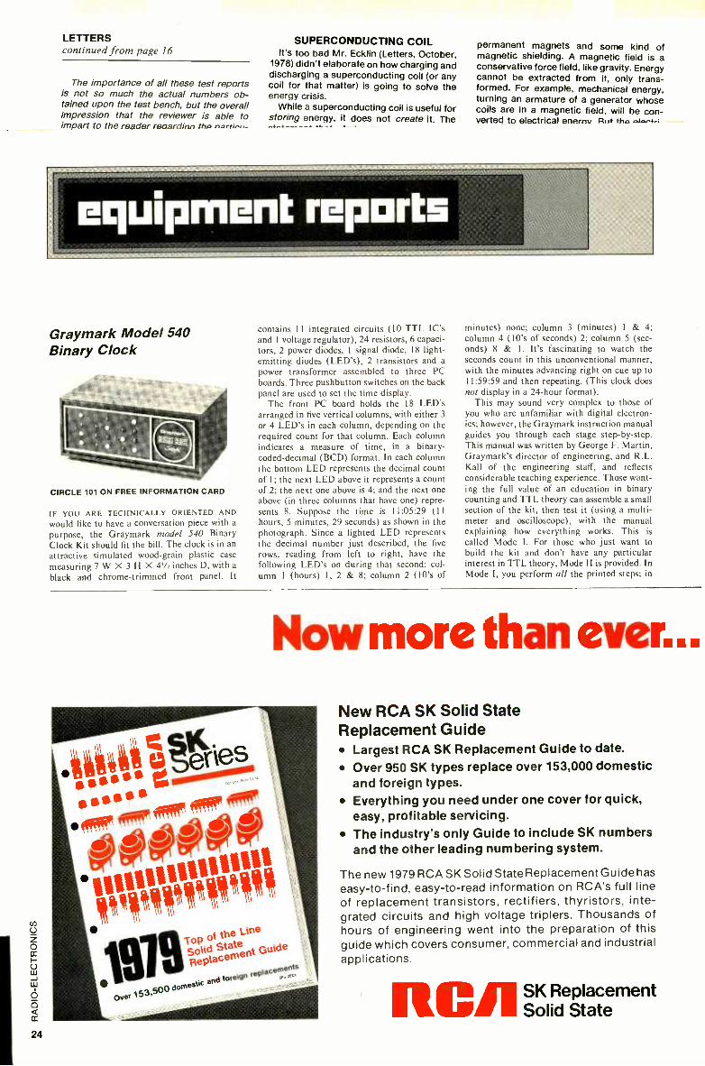
Graymark Model 540 Binary Clock
CIRCLE 101 ON FREE INFORMATION CARD
IF YOU ARE TECHNICALLY ORIENTED AND
would like to have a conversation piece with a
purpose, the Graymark model 540 Binary Clock Kit should fit the bill. The clock is in an
attractive simulated wood -grain plastic case
measuring 7W X 3H X 4'/: inches D, with a
black and chrome -trimmed front panel. It
contains I I integrated circuits (10 TTL IC's and 1 voltage regulator), 24 resistors, 6 capaci- tors, 2 power diodes, 1 signal diode, 18 light - emitting diodes (LED's), 2 transistors and a
power transformer assembled to three PC boards. Three pushbutton switches on the back panel are used to set the time display.
The front PC board holds the 18 LED's arranged in five vertical columns, with either 3
or 4 LED's in each column, depending on the required count for that column. Each column indicates a measure of time, in a binary- coded- decimal (BCD) format. In each column the bottom LED represents the decimal count of 1; the next LED above it represents a count of 2; the next one above is 4; and the next one above (in three columns that have one) repre- sents 8. Suppose the time is 1 1:05:29 (11
hours, 5 minutes, 29 seconds) as shown in the photograph. Since a lighted LED represents the decimal number just described, the five rows, reading from left to right, have the following LED's on during that second: col- umn 1 (hours) 1, 2 & 8; column 2 (10's of
minutes) none; column 3 (minutes) 1 & 4; column 4 (10's of seconds) 2; column 5 (sec- onds) 8 & 1. It's fascinating to watch the seconds count in this unconventional manner, with the minutes advancing right on cue up to 1 1:59:59 and then repeating. (This clock does
not display in a 24 -hour format). This may sound very complex to those of
you who are unfamiliar with digital electron- ics; however, the Graymark instruction manual guides you through each stage step -by -step. This manual was written by George F. Martin, Graymark's director of engineering, and R.L. Kall of the engineering staff, and reflects considerable teaching experience. Those want- ing the full value of an education in binary counting and TTL theory can assemble a small section of the kit, then test it (using a multi - meter and oscilloscope), with the manual explaining how everything works. This is
called Mode I. For those who just want to build the kit and don't have any particular interest in TTL theory, Mode II is provided. In Mode I, you perform all the printed steps; in
Now more than ever...
40. t?éries
00000 VIVVVV1111
lop ifstate line
Replacement Guide
lacements
153 Soo domestic and foreign
rep
Over
New RCA SK Solid State Replacement Guide
Largest RCA SK Replacement Guide to date.
Over 950 SK types replace over 153,000 domestic and foreign types. Everything you need under one cover for quick, easy, profitable servicing. The industry's only Guide to include SK numbers and the other leading numbering system.
The new 1979 RCA SK Solid State Replacement Guide has
easy -to -find, easy -to -read information on RCA's full line of replacement transistors, rectifiers, thyristors, inte- grated circuits and high voltage tripiers. Thousands of hours of engineering went into the preparation of this guide which covers consumer, commercial and industrial applications.
RC,'.
SK Replacement Solid State

Mode II, you only read and perform the steps that are printed in red.,
The manual is printed throughout in two colors, has over 100 explicit illustrations and diagrams and contains virtually no errors. (Ex- ceptions: On page 34, step 5 refers to Fig. 49, but should refer to the foil side of the PC board; and on page 41, step 35 should be printed in red.) The operational theory of the clock is extremely detailed, and is accompa- nied by many block diagrams, charts, timing diagrams and even IC data sheets. A complete parts list and a schematic diagram of the clock are also included.
The PC boards and parts are all new and of top quality. The LED's seem to be graded for equal brightness, and an assembly aid is pro- vided for their proper positioning and align- ment. Every single component needed is in- cluded -even a nylon cable tie and solder. The PC boards are masked to avoid solder bridges, and parts locations are silk- screened on the component side of the boards to insure proper assembly. The only tools you'll need are a 20- to 30 -watt soldering iron, a wire stripper, diag- onal cutters, a Phillips -head screwdriver and long -nose pliers.
Constructing the kit is simple following the detailed step -by -step instructions, but it is time consuming. There are over 350 solder connec- tions, 21 jumpers and 29 board- interconnect- ing wires. It took four hours to assemble (fol- lowing the Mode II red instructions), and working slowly and carefully to avoid later problems. This care was rewarded by the clock working perfectly when plugged into the 110 - VAC line. Time -setting is accomplished easily with the SLOW, FAST and HOLD switches once the time -readout format is understood. Count-
ing is controlled by the line frequency (either 50 Hz or 60 Hz, jumper -selected), so this clock provides long -term accuracy, since pow- er companies keep a close tolerance on the average output frequency.
The model 540 Binary Clock sells for $39.95 in kit form including the manual (post- paid in the United States) from Graymark International, Inc., 1751 McGraw Ave., Dept. RE, Irvine, CA 92714. Foreign orders add $6 postage and handling. California residents add state and local taxes as applicable. The manual is available separately for $2. R -E
BSR System X70 AC Remote Control
CIRCLE 102 ON FREE INFORMATION CARD
HERE IS A REMOTE -CONTROL SYSTEM THAT
gives you, at your fingertips, complete control of the lights and appliances in your home with- out getting involved in any special wiring. You use the house wiring as the signal- carrying system. For example, if you suddenly hear a
strange noise downstairs, you push a button on
the control unit and it turns on the lights. With the BSR System X10 light and appliance com- mand console by your bedside or chairside, you can turn lights on and off, dim or brighten them at the touch of a button. You can even use the System X10 to trigger a simple alarm device.
Using this system, you can literally operate almost every light and electrical appliance in
your home without leaving your easy chair. That means you can turn air conditioners on and off, as well as TV's, stereos or lights. The basic system comes with a command console, appliance module and a couple of lamp mod- ules. For less than $100 it is possible to buy a
System X10, including enough modules to control lights and appliances at up to four different locations. The command console, model SC -311, through its keyboard, permits remote control operation of lights or appli- ances in up to 16 separate locations. (By rotat- ing a bottom of the control switch, more groups of 16 controlled switches can be provid- ed.) It plugs into any AC wall outlet in the house and transmits FM command signals over the electrical wiring. Optionally available is a cordless controller, model CC40I. It transmits signals to the ultrasonic command console over distances of as much as 30 feet. All functions of the command console are duplicated on the cordless controller.
The lamp module, model LM50I, will con- trol any incandescent lamp rated up to 300 watts. Functions include on and off, bright and dim.
The appliance module, model AM601, turns an appliance on or off; a TV, stereo, fan, etc. Maximum appliance ratings on a resistive load are 15 amp; motorload, '/3 horsepower; incan- descent lamp, 500 watts. A wall- switch module
... RCA SKs make it easy for you to offer reliable service at a profit. New Numbering System All SKs now feature, where applicable, the product num- bers of the other leading system used by ECG,* REN and TM. For example, whenever an SK device replaces an ECG device, the ECG number is now part of the SK number. (SK 3444, a direct replacement for ECG 123A, is
now listed as SK 3444/123A.) The new 1979 RCA SK Solid State Replacement Guide is the only guide you need. You can buy and install RCA SK devices with confidence that the replacement is right and the quality is right too.
Best of all, RCA Top of the Line quality means fewercostly call -backs and more profitable customerservicing foryou. See your RCA SK distributor for all your solid state re- placement needs and ask for your copy of the new authori- tative RCA SK Replacement Guide, SPG 202X; or send your request with-check or money order for $1.50 to RCA Distributor and Special Products, P.O. Box 597, Wood- bury, N.J. 08096.
'ECG is a trademark of GTE Sylvania
I

is also available. It looks like an ordinary wall switch, operates like one, installs like one, but can also be remotely controlled.
When we first looked at the unit, we wondered what would happen if we had one, an upstairs neighbor had one, or the guy next door had one; if his units would turn mine on, and if my units would turn his on. Obviously, if our signal gets into his apartment, it will. But BSR is just one little step ahead of us. There are 16
separate ranges that will automatically prevent overlap. A simple dial selector on the unit codes the letters A through P for those nonin- terfering signals.
I can't think of an easier way to remotely control electrical functions in anyone's home or apartment, and the price is surprisingly reasonable for what the equipment can do. This is one of those products among the many
we've tested that I am going to want for myself.
The System X10 is available from Ad- vanced Electronics, 54 W. 45 St., New York, NY 10036. R -E
RCA CDP18S020 COSMAC Evaluation Kit THE RCA 1800 SERIES COSMAC MICROPROCESSOR
and its associated family of devices have a couple of unique characteristics. First, because they are COS /MOS devices, the power drain is low, starting at the milliwatt level. Single -IC standby memory power is also in the low milli - watt range.
Second, the 1800 family tolerates an unusu- ally wide power supply range -3 to 12 volts for
SUBSCRIBE TODAY. SPECIAL 32 48CE
Radio IM MOMS+ ...
easy to baud
uses discrete tit's roundup for hobbyà
for yew project
special teat,
what they how to se
Oerilther
pro's wad how to roundup of
SAVE TIME AND MONEY EVERY MONTH.
Have Radio -Electronics delivered to your door every month, and be sure of getting your copy even if your local newsstand runs out. Save money too while you enjoy the best electronics magazine of all. Every page is packed with excitement and ideas, with news you won't want to miss, projects you'll want to build, servicing tips you'll want to learn, equipment test reports you'll want to read before you buy. Make sure you get it all, by making sure you get every issue of Radio -Electronics from now on. Check out the subscription offers on the coupon below -offers that can save you up to $18.00 off the newsstand price -and check off the one you like best. Do it today, and get in on all the electronics excitement every month.
41G9
Mail to: Radio -Electronics SUBSCRIPTION DEPT., P.O. BOX 2520, BOULDER, COLO. 80322
Name (please print)
Address
City State Zip Code
Indicate the offer you prefer: i Year -12 issues ONLY $9.98 (You save $5.02 off newsstand price.) 0 2 Years -24 issues ONLY $19.00 (Save More! $11.00 off newsstand price.) n 3 Years -36 issues ONLY $27.00 (Save Even More! Save $18.00 off newsstand price.)
Payment enclosed Bill me Check here if this is a new subscription. 0 Check here if you are extending or renewing your subscription.
Extra Shipping: Canada $3.00 per year, all other countries $5.00 per year.
CIRCLE 103 ON FREE INFORMATION CARD
the CDP1802 with a 3.2 -MHz clock. And the operating temperature range for the full -speed processor and certain memory products covers the full -55 to 125 °C temperature range. This is important if your microprocessor -controlled gadget will form part of an automotive sys- tem.
The processor instruction set is based on a 16- X 16 -bit scratch -pad organization that provides good programming flexibility..
The RCA CDP18S020 Evaluation Kit is a relatively inexpensive tool with which to learn about the RCA 1802, prototype a microcom- puter system, or develop software. A 20 -mA loop or RS232C terminal is normally required to use the Evaluation Kit, although a simple keyboard or switch interface can be designed. Board dimensions are 14 X 9.7 inches, includ- ing fully decoded prewired locations for expan- sion to 4096 bytes of random -access memory (RAM), and a 6- X 4 -inch user area wired to accept standard DIP packages.
Three edge connectors provide access to the microprocessor pins and the user input-output (I /O) area, and connect to external power sources and peripheral devices. The kit comes with a 2 -MHz crystal which, for the 16- and 24- clock -period instructions, calculates to 8 -gs or 12 -gs execution times. A 6.4- MHz oscilla- tor reduces these values to 2.5 and 3.75 pis.
A 5I2 -byte ROM is assigned address space from 8000 to 81 FF and permanently stores the UT4 monitor program. A 32 -word RAM start- ing at 8C00 is used by the utility program to store register contents. Two supplied RAM IC's fit into the first two locations in the 4K memory area for an initial 256 -word user programming space.
System operation is controlled by three pushbuttons and a toggle switch. The RESET pushbutton intializes the CPU and control logic: RUN U (Run Utility) gives control to the ROM monitor program by starting execution at 8000. The RUN P (Run Program) pushbut- ton starts program execution at 0000, where the first user's program instruction is usually entered. The CONTINUOUS /STEP toggle switch lets the user choose between the normal clocked mode or single -cycle operation, where individual program steps can be dissected down to 2 machine or 3 machine cycles -per- instruction.
A series of 29 LED's display the status of the 16 -bit memory address bus, the 8 -bit data bus, the SO and SI processor state codes, the CLEAR and WAIT control signals, and the processor's Q flip -flop.
Bidirectional communications to a data ter- minal are provided by interface circuits that use the Q flip -flop for output and the EF4 flag to input the serial data. Detailed instructions show how to hook up to current loop terminals such as Teletypes, and to EIA RS232C inter- faces such as Texas Instruments' Silent 700 terminal. Parallel 8 -bit input and output ports are included in the kit.
External power supplies are required -of 5

*M0 112233445566778899AABBCCDDEEFF;
100020 123456789ABC 1029384756; 000F AFBECD
DE,
*?M0 30 0000 1122 3344 5566 7 788 99AA BBCC DDEE FFAF;
0010 BECD 0000 0000 0000 0000 0000 0000 0000;
0020 1234 5678 9ABC DE10 2938 4756 0000 0000
*?M20 10
0020 1234 5678 9ABC DE10 2938 4756 0000 0000
*?M8C00 20
8C00 DODO 8CO2 FF00
8C10 FA24 FF66 FF02 '$P
*$P0100
814F 9401 804A BDOO EF82;
7F00 80EF 0000 2800 8000
FIG. 1
volts at 600 mA, or 10 volts at 200 mA with a
separate 5 -volt 400 -mA supply for the LED's.
Assembly Kit assembly was pleasantly uneventful with
the help of a high -quality, double -sided PC board with plated- through holes. Close PC runs are necessity on microcomputer boards, and careful soldering and inspection tech- niques are a must. Sockets are provided for the microprocessor and utility ROM IC's, but, as
always, I recommend using additional sockets or Molex pins to mount some or all of the remaining 22 circuits.
The checkout procedures consists of mea- suring the resistance of the supply input leads, and loading and executing a four -instruction program that sets and resets flip -flop Q.
Figure 1 demonstrates the writing of data to memory, the reading of data from memory, and starting programs. The UT4 program recognizes three commands corresponding to each of these functions.
After pressing the RESET and RUN u push- buttons, type either a carriage return or a line feed depending on whether your terminal is
connected for full -duplex or half -duplex opera- tion. Full- duplex operation requires the com- puter to echo back characters typed on the keyboard to the printer, since the two terminal functions are completely isolated. Based on the first character typed, the utility program sets up to echo or not, and calculates the bit timing necessary to talk and listen to the terminal.
Figure 1 shows how the three -command repertoire works. First, you enter a program either from the keyboard or from punched paper or magnetic tape. The command !M is
the write- memory command, which is immedi- ately followed by the address where the input should be entered -in this case, 0 or 0000. The space after the 0 separates the address from the data. Next, the program instructions or data are entered in hexadecimal format, with each two characters accounting for a single memory word. In hexadecimal or base 16 format, addi- tional symbols are needed for numbers be- tween 10 to 15. Letters from A through F are used to represent 10 through 15 with a single symbol.
Spaces can be imbedded between words if desired. At the end of the line, you have a
number of choices. In Fig. I the first line is
terminated by a semicolon. This told the machine I wasn't finished yet, and that I will give a new address and more input. Everything else was ignored until the next hexadecimal
digit. I then added an extra line feed to make the printout more legible. On the second line I
started to type 10 but decided I really wanted to enter more data starting at address 20. The system (being forgiving) only pays attention to the last four numbers entered, so I typed 0020 (or I could have typed 020 since one 0 was already there from the I0). I then hit the space bar and typed in the data.
This time I hit a comma at the end of the line that told the machine I still had more data to enter but wanted to continue on the next line. With the comma the data continues in sequence and a new address is not given.
At the end of the third line I decided to go back and fill in data starting at 000F; so I used the semicolon again.
Finally, at the end of line 4, I simply used a
continued on page 32
NEW FROM LEADER
High Performance, Low Cost, 10 MHz Oscilloscopes.
Model LBO -513 Single Trace $495 with probe.
® s
Model LBO -514 Dual Trace
$645 with probes.
1 mV Sensitivity. Complete Triggering and Display Controls. 8x1 0 cm CRT.
m
NNIVEIIS Send for Complete Data.
All Leader Instruments are Backed by a Two Year Warranty!
151 Dupont Street, Plainview, N.Y. 11803
Regional offices: Chicago á Los Angeles
East Coast: (518) 822 -9300: West Coast: (213) 882-4335
Call Toll Free: (800) 645 -7120 For the Name of Your Nearest Distributor.
When Quality Counts .. .
LEADER Instruments Corp.
CIRCLE 52 ON FREE INFORMATION CARD

Train with NTS for the Microcomputers, digital
the first name
Microcomputers
nn_n_ WAN ,_.ñ: . w
a:±ww. ww
,.e.nnn+«+innuwr ,Wraa,nna.n ,KnannnnunNoma ,.
The world of electronics is daily becoming more challenging. Technology is growing more specialized, and the importance of digital systems increases every day. Test instruments, home entertainment units and industrial control systems are all going digital. And now, NTS training programs include a wider choice of solid -state and digital equipment than ever before offered in any home study course: Advanced NTS /Heath digital color TV (25" diagonal with optional programming capability), NTS /Heath microcomputer, digital test equipment, digital stereo receiver (70 watts per channel), NTS compu- trainer, plus much more state -of- the -art equipment to make your training exciting and relevant.
The equipment you receive with NTS training programs is selected to provide you with a solid
background in electronic systems. Kits and lessons are designed to work together to demonstrate electronic principles and applications. The kit -building not only shows you how electronic hardware functions, but how various circuit designs accomplish different purposes. Your lessons guide you through any number of experiments associated with many projects. This is the Project- Method, and it works. Step -by -step, you learn how and why digital electronics has become a part of our world, and the even bigger role it is sure to play in the future.
Whether you are looking for training in Consumer, Commercial, or Industrial electronics, NTS offers fourteen courses, some basic, many advanced, in
several areas of electronics. An all -new full -color NTS catalog shows you what each course covers,

electronics of the future. systems and more...from in home study.
Simulated TV Reception
and every piece of equipment included.
Send for it today, and see for yourself what's really
happening in electronics training technology at NTS.
Find out how much has changed, and what new
directions the field is taking. You'll probably want to
be a part of it.
It's free. Just mail the card or coupon. Today.
NO OBLIGATION. NO SALESMAN WILL CALL. APPROVED FOR VETERAN TRAINING.
NATIONAL TECHNICAL SCHOOLS TECHNICAL -TRADE TRAINING SINCE 1905
Resident and Home -Study Schools 4000 South Figueroa St., Los Angeles, Calif. 90037
- NATIONAL TECHNICAL SCHOOLS Dept. 206 -079 4000 South Figueroa Street. Los Angeles, Cal forma 90037
Please send FREE Color Catalog and Sample Lesson.
Color TV Servicing B & W TV and Radio Servicing FCC License Course Electronic Communications Electronics Technology Audio Electronics Servicing Digital Electronics
[ 1 MicroComputers /MicroProcessors
I I I I I I I
Name
Address
Apartment Number Age
City
State lip ]Check if interested in G.I. Bill information.
LiCheck if interested ONLY in classroom train ng in Los Angeles.
I I I I I I I
A P Terminal and Distribution Strips are ideal building blocks for your breadboarding. Now you can put together as sim- ple or as elaborate a breadboard as you want -and be sure of top quality all the way -and pay only for what you need. Using A P Termi- nal and Distribution Strips as mod- ules is the world's most economical way to assemble full -performance solderless breadboards.
You know how our strips work. Your electronic components plug right into the spring clip terminals behind
each hole. You complete your cir- cuits with ordinary solid wire jump- ers -you don't need special patch cords. Terminals clip tight, make su- perb contact time after time. (They're noncorrosive copper alloy 770.)
These versatile building blocks come in a wide variety of shapes and sizes, and we include hardware and mounting templates with each strip. You get all the flexibility in the world.
Where? At your nearby A P Prod- ucts dealer. Need the address? Phone (toll -free) 800 -321 -9668. And ask for the complete A P catalog, The Faster and Easier Book.
A P PRODUCTS INCORPORATED Box 110 -B 72 Corwin Drive Painesville, Ohio 44077 Tel. 216/354 -2101 TWX: 810- 425 -2250
Faster and Easier is what we're all about.
CIRCLE 56 ON FREE INFORMATION CARD
EQUIPMENT REPORTS continued from page 27
carriage return, indicating I was through, and the machine responded with the prompt aster- isk on the following line.
At this point, you're ready to check by read- ing out memory contents with the ?M com- mand. Again, you use 0 as the starting address; however, the 30 is not data but the number of words in hexadecimal format to be typed out - 3016 = 3 X 16 = 4810 words. The next three lines represent the response to that command. The first four columns display the starting address for each line followed by 16 words grouped by two's. The last byte on the 0000 line is the AF that I inserted at address 000F on line 4.
Note the format that the machine uses to output memory contents. The first two lines begin with addresses and end with semicolons, and the third line starts with an address (0020) and ends with a carriage return. This allows the data to be stored on tape in this format and then later be read back in using the compatible !M command.
The next group of lines demonstrate a mem- ory dump of 1016 or 1610 words starting at 0020.
The UT4 monitor program uses a 32 -byte RAM starting at 8C00 to store the 16 scratch - pad microprocessor registers. This feature is helpful in troubleshooting, but care must be used since certain registers are modified by the system. The program cannot be restarted from an intermediate point after being interrupted by inserting an idle instruction unless the registers are restored.
The next three lines in Fig. 1 show how the register RAM is printed out with the ?M8C00 20 command. Characters RO and R7 are displayed on the line prefixed by 8C00, and R8 through RF on the line starting with 8C10.
Command $P starts program execution. If no address is given, execution begins wherever the program counter is set, usually at 0000. Otherwise, the program is started at the address typed immediately after $P.
A large loose -leaf binder comes with the kit. It includes detailed sections on kit assembly, design and operation of the system, the utility program (including listing), application notes on I/O and control, software and memory.
The CDP18S20 evaluation Kit is priced at $249 and is available from RCA Solid State Division, Somerville, NJ 08876, or from RCA Solid State distributors. R -E
"No matter what the project he's working on is supposed to be -it ends up being a light dimmer."

ALL THE MOST WANTED FEATURES
AT A MOST WANTED PRICE... BIG y2" HIGH LCD DISPLAY
USE INDOORS OR OUT
200 HOUR 9V BATTERY LIFE
AUTO ZERO, POLARITY, OVERRANGE INDICATION
100 mV DC F.S. SENSITIVITY
19 RANGES AND FUNCT'ONS
ONLY74.95 HICKOK T-1E HICKOK ELECTRICAL INSTRUMENT CO 10514 Dupont Avenue Cleveland. Ohio 44108 (2161 541 -8060 1W'X. 810 -421 -8286
Here is the handfull of accuracy you've been waiting for Hand somely encased.
Compact. Efficient. Onlyl2ounces. Hickok's exciting, new LX 303, 3%
digit Mini- Multime- ter with high quality components, one year guarantee and rugged Cyco- lac case offers
features previously found only in ex-
pensive units.. .at a price under $75.00!
So why wait any longer? The
amazing LX 303 is here, NOW!
Another American made test equip-
ment breakthrough from Hickok. The Value Innovator. Order today!
Removable cover stores test ad set furnished as part of the unll
M .r». K : K 1L,,, X 303
Available accessories include Ad- adapter, padded vinyl carrying cas 40KV Dr r - A -1, ,hunt
X10 DCV probe adapter available for protecting input up to 10KV
CIRCLE 48 ON FRIEE INFORMATION CARD
SPECIFICATIONS: DC VOLTS (5 RANGES): 0.1 mV to 1000V AocLracy + 0.5% rdg ±0.5% f.s.; Input imped: 10M j:; Max.. input 1kV except 500V on 200mV range. AC VOLTS (40Hz to 5kHz): 0.1V to 600V; Accuracy: ± 1.0% rdg ±0.5% f.s. ( -2dB max. at 5kH,zi; Max. input: 600V. RESISTANCE (6 LOW POWER RANGES): 0.1 to 20Mí) ; Accuracy: +0.5% rdg ±0.5% f.s. ( ±1.5% rdg on 20M(1 range); input protected to 12074;---tif ranges.
CURRENT (6 RANGES):.01 nA to 1C'OnA Accuracy: ±1.0% rdg -`0.5% f.s. DIMENSIONS AND WEIGHT: 5 -7/8" x 3-3,8" a.
1 -3/4 ", 12 oz.; POWER: 9V batt. (not inc:.l Cdr l ckok AC adapter; READ RATE: 3 /sec. OPERAT NG TEMPERATURE: 0" -5 ' :'C.
r e your loca Hickok distributor or order below
ADVi411NC ELECTRONIC
-0 ORDER CALL TOLL FREE 800 -223 -0474
54 West 45th Street. New 4vrk, N;1: 10036 212- 637 -2224
PLEASE SEND ME Hickok LX303 Digital Multimeters @ 74.95 ea.
RC -3 AC Adapter, 11SVAC (220VAC avail.) @ 7.50 ea.
CC -3 Deluxe Carrying Case @ 7.50 ea.
VP -10 X10 DCV Probe Adapter @ 14.95 ea.
CS -1 10A DC Current Shunt @ 14.95 ea.
VP -40 40 KV DC Probe @ 35.00 ea.
P.:yment encl. Bill my: Master Charge VISA
mAim 011111MI
Account # Exp. Date
Name
Address City Stae Zip
L Add $3.00 Postage and Handling, N.Y. residents add sales tax. RE-7

GE HAS PUBLISHED A SEQUEL TO YOUR FAVORITE BOOK.
Especially if you're replacing semi- conductors. Even then, you may never
read all of this 416 -page catalog, but you'll find yourself referring to it every day.
This year's edition is expanded to give you quick &easy cross reference data on high voltage triplers ... more
parts identification charts ... application charts for an "instant view" of
transistor specifications. As before, our unique parts ID num-
bering system -which no one else in the
industry offers -tells you at a glance almost all you need to know when making a replacement. For instance, GE5ZD3.3 stands for a 5 -watt, 3.3 -volt zener diode by General Electric. Simple enough?
For your free copy of this valuable addition to your service shelf, see your authorized GE distributor today.
This could be the best book you'll never stop reading this year.
WE'RE AT YOUR SERVICE. Tube Products Department- Owensboro, Kentucky 42301
GENERAL ELECTRIC

L J
Heart Rafe MONITOR An instantenous check on heart -rate activity is essential when
engaging in meditation, Yoga or an exercise program for health and
physical fitness. This cardiotach provides a direct readout of your heart rate.
MARK C. WORLEY
THE CARDIOTACH IS AN ADVANCED, SOLID -
state design useful for experimental or clinical monitoring of the human heart rate. The term "cardiotach" is derived from the Greek word kardia, meaning heart, and the Greek word takhos, mean- ing speed. Thus, cardiotach literally means heart speed or heart rate.
Research has shown that the heart rate is generally proportional to the body's level of tension, excitement or anxiety; therefore, a slower heart rate can be used as an indicator of the degree of relaxation. For those practicing various methods of meditation or tension -reducing relax- ation, the Cardiotach can be useful for displaying the relative degree of calm- ness.
Experimenters and clinical technicians can use it as a response indicator of anxi- ety states or relaxation responses to such external stimuli as words, music, odors, visual displays, etc. The pulse rate in-
crease is usually quite rapid in response to anxiety -producing stimuli and can be a
more accurate indicator of the body's state than verbal responses. This is one reason why a heart rate monitor usually forms part of a polygraph or "lie detec- tor."
Often, during relaxation- training ses- sions, an aural indicator can disturb the state of relaxation for the participants.
The Cardiotach has a front panel meter that provides a visual indication of the heart rate.
For those physical fitness enthusiasts who might want to monitor heart rate in
relation to physical stress, the Cardiotach could be useful, too. It is not, however, a
portable (battery- operated) instrument, and is subject to false readings from muscle and sensor movements. There- fore, its best application might be as a
before -and -after measurement while comfortably seated or otherwise station- ary.
In addition, it's fun and satisfies your curiosity to know your heart rate and see the meter display it directly in BPM (Beats Per Minute).
Design objectives in devising the Car - diotach were to use inexpensive, readily available components, provide an accura- cy of at least ± 5% and avoid potential shock hazard. All these criteria were met far beyond expectations. The accuracy of the instrument, depending upon meter linearity, is better than 5 %, the unit costs less than $100 to build, and all the components, except for the sensor, can be obtained from mail -order distributors.
Circuit description The circuit senses each heartbeat via an
infrared optocoupler /sensor and triggers
on the "R" -wave, which is the largest - amplitude signal found in the heartbeat waveform (see Fig. 1). Because of this, it
was decided to simply use amplitude discrimination in order to have the R- wave trigger the tachometer circuit. Thus, the circuit directly displays the R-
wave repetition rate.
R
P T P T
FIG. 1 -HIGH AMPLITUDE PULSE of the heart- beat waveform.
Figure 2 is the block diagram of the Cardiotach circuit; Fig. 3 is the complete schematic diagram. The circuit is divided into eight basic sections: sensor, bandpass amplifier, Schmitt trigger, charge pump, meter circuit, beep -tone generator, cali- brator and power supply. We'll consider the operation of each section in turn and see how they all combine into one instru- ment.
1. The sensor is an infrared reflective sensor (manufactured by Optron, Inc., 1201 Tappan Circle, Carrollton, TX 75006) containing an infrared emitting diode and an infrared sensitive phototran- sistor that are shielded from each other
35
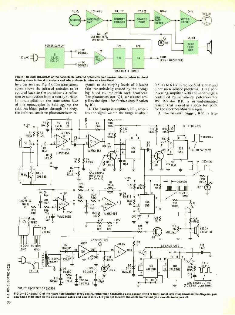
R16. 10K:
D 1C1-a & b 0.1,1C2 Q2, IC3
BANDPASS SCHMITT CHARGE AMP TRIGGER PUMP
117VAC * POWER SUPPLY
CALIBRATE/ OPERATE
+12V
S3 O
IC7
5V
IC8 IC9
T1
D2, D3 ICE, D4
=10 +4
SOURCE
-12V REG
O SOURCE
CALIBRATE CIRCUIT
IC4-a
LOW PASS FILTER
FIG. 2 -BLOCK DIAGRAM of the cardiotach. Infrared optoelectronic sensor detects pulses in blood flowing close to the skin surface and interprets each pulse as a heartbeat.
by a barrier (see Fig. 4). The transparent sponds to the varying levels of infrared cover allows the infrared emission to be skin transmissivity caused by the chang- coupled back to the transistor via reflec- ing blood volume with each heartbeat. tion or conduction from a nearby surface. The phototransistor, Q1, senses and am- In this application the transparent face plifies the signal for further amplification of the optocoupler is held against the by ICI. skin. As blood pulses through the body, 2. The bandpass amplifier, ICI, ampli - the infrared -sensitive phototransistor re- fies the signal within the range of about
JI
+12V
R1
47052
o
VD
R4110K
IL- R5 C2
1 MEG .01
*R2 10K 2
+1% Cl
10µF
R3 100K
OEDI 11
OPB706
vvr +12V 8
1 ICI -a
C3
.22
+ 4
12V
t/2MC1458
1 +12V
(FROM IC3,
47µF
C10 2
PIN 3) + 47µF
3
RIB R19
IC4-a
4
100K 100K + -12V C11- 1/2MC1458
106 10µF T 7812
R9
100K GAIN
IN OUT OUT IN
GND GND
IC7
78L05
i C4 R7
.1 100K
1/2 M C 1458
R8 R6
1K 1 MEG R11 1 MEG
R10 1052
R12 100K
C5 ^ .22
TP1
11,
O 03
IC4-b
_ METER DRIVE
METER
1.5Hz
(60Hz +40 OUTPUT)
105, 04
BEEP TONE
GEN (
0.5 Hz to 6 Hz to reduce 60 -Hz hum and other noise -source problems. It is a non - inverting amplifier with the variable gain controlled by sensitivity potentiometer R9. Resistor RIO is an end -mounted resistor that is used as a scope test point for the electrocardiogram signal.
3. The Schmitt trigger, IC2, is trig-
R13 27K
R20 1052 yy ---0 TP2
CAL SIGNAL INPUT POINT (FROM C19)
M1
100µA
R21 R22 9.1K 7.5K
6
4.-"Sf-17"6-4-C12 5 IC4-6
10µF
1 R23 1/2MC1458
+12V
R24 R37 10K 82K
7 IC2
555
+12V
R15 100K
C7
01
3 1(--
R17 2.2K
02 6
8
IC3
555
*R14 + C8
10K 1 10µF
TO +12V
112 100mSec
- . T0 "A" (R18)
r---300mSec
R29 1K
01
IN 914
R28 10K
R38 100K
4 8
IC5
555
C13 1
1
R25 47K
V1
D2
1N4001 Ti 04 I
C14 ±
12.6VAC 1000µF
T 1.2 0 500 m A
1 = L = D3
1N4001 SOURCE() -144,-- C16R3 C16.... D4 C17
1000µF I+ 12052 12V 1W
47/1F _ = 1N4742 +I µ
7812 +12V SOURCE
l OUT UT
Cl 5I 47µF
-12V
Q1, 02, 03-2N2926 OR 2N3904
R34
IN
39052
'5, LED 2
OUT
R35 1K
-.I r -300mSec
R114 JIIIUIIIUIIIL
R26 1K
03
14
D5 12
5.1V l 1N4733
1
/ 500Hz = f/ TONE
R31 18052
R32 5K
VOLUME
S3 CALIBRATE
IC8
74LS90
3 10 6
111 12
7
3
10 14
IC9
74LS107
17
R30 39052
LED 1
S
R38 47052
+I( J_ 136 J = -o-
R36 100K
C19 /
CALIBRATE OUTPUT (TO C5-R11 JUNCTION)
ß12OR GREATER
C18 10µF
1.5Hz 5V P-P
FIG. 3- SCHEMATIC of the Heart Rate Monitor. If you desire, rather than hardwiring opto- sensor OED1 to front -panel jack J1 as shown in the diagram, you can add a male plug to the opto- sensor cable and plug it into J1. If you opt to leave the cable hardwired, you can eliminate jack J1.

IR EMITTING LED
BARRIER
IR SENSITIVE TRANSISTOR
DENOTES PIN 1
2 3D
FIG. 4- CONSTRUCTION and pinout for the OPB -706 infrared reflective sensor.
gered by a negative pulse from Q2 to produce a 300 -µs squarewave that helps eliminate multiple triggering on both the R- and T- waveforms. The pulse is also used to light LEDI and trigger the beep generator IC.
4. The charge pump, IC3, produces a
100 -µs pulse each time it's triggered by a
heartbeat signal from IC2. Resistor RI7 is an internal calibration potentiometer that adjusts the width of the pulse. The actual pulse width is dependent upon the circuit values and tolerances in the low -
pass filter circuit. Quality components are a must in this part of the circuit in
order to maintain stability. 5. The low -pass filter, IC4, is used to
smooth the 100 -ms pulses into a DC volt- age that is proportional to the heart rate. This voltage can be measured at R20, which is an end -mounted resistor used as
a test point during calibration. Integrated circuit 4 -b is a voltage -to- current con- verter used to drive meter M1. Input resistors R21 and R22 filter and scale the meter drive circuit to produce a 60 -µA current for a 1 -volt input. Since the meter is in the feedback path of IC4 -b, its inter- nal resistance and any thermal resistance changes will have no effect upon the
--.09 --
current through it. Diode D1 prevents reverse meter current, and since it also is
in the feedback path, it has no other effect on the meter. Resistor R24 is used to cancel offset voltages and to position the meter needle during calibration. Re- sistors R21 and R22 are selected for a
series resistance of 16,660 ohms, result- ing in a 60 -µA- per -volt scaling of IC4 -b's meter drive circuit. (The meter is in- tended to be calibrated with 0µA as 50 BPM, 20 µA as 70 BPM and so on, with 100 µA as 150 BPM. If a 50 -µA meter is
used, R21 and R22 must be doubled in
value to equal a total resistance of 33, 330
ohms.) The charge pump and filter circuit are
designed to provide 1 -volt DC to IC4 -b at
60 BPM (or I Hz) and to increase that voltage linearly with an increase in fre- quency. This results in a 60 -µA change through the meter when the heart rate increases from 60 BPM to 120 BPM.
6. The beep -tone generator, IC5, pro- duces a 300 -ms beep with each heartbeat. The generator operates in a keyed and modulated mode controlled by IC2 and Q3. As long as pin 4 is kept low, IC5 does
not oscillate. When IC2 pin 3 goes high, it allows IC5 to produce a tone for the duration of the pulse of IC2. The fre- quency, or pitch, of the tone from IC5 increases with an increased heart rate and vice versa. The voltage on pin I of IC4 -a
varies the conduction of Q3, which, in
turn, varies the trip point of IC5 and its
operating frequency. The response.of Q3
is not linear, but it does vary noticeably with the heart rate. If this feature is not desired, eliminate R25 R27 and Q3. No jumper connections are needed; just leave IC5 pin 5 disconnected.
7. The calibrator circuit, IC7 -1C9, generates a 1.5 -Hz (or 90 -BPM) square - wave that is derived from the 60 -Hz line frequency. It is used to initially calibrate the Cardiotach and for later recalibration
FIG. 5 -FOIL PATTERN for the printed -circuit board used in making the cardiotach. The board may
be cut in two and the pieces wired separately. Pattern is shown half -size.
Resistors Y. watt, 10 %, unless otherwise specified
Resistors R1 -470 ohms, 1/2 watt R2,R4,R14,R23,R28- 10,000 ohms R3, R7, R 12, R 15, R 18, R 19, R36, R38 -
100,000 ohms R5,R6,R11 -1 megohm R8,R26,R27,R29,R35 -1000 ohms R9- 100,000 -ohm linear pot (sensitivity
control) R10,R20 -10 ohms, '/2 watt (test points 1
& 2) R13- 27,000 ohms R16,R24- 10,000 -ohm trimmer R17 -2200 ohms R21 -9100 ohms, 1% R22 -7500 ohms, 1% R25- 47,000 ohms R30 -390 ohms R31 -180 ohms R32- 5000 -ohm, audio taper pot with
switch R33 -120 ohms, '/2 watt R34 -390 ohms, 1/2 watt
PARTS LIST
R37- 82,000 ohms R38 -470 ohms Capacitors C1,C6,C11,C12,C18 -10 AF, 16 volts,
electrolytic C2, C7 -.01 µF, ceramic C3, C5 -.22 µF, 50 volts, Mylar C4, C13, C19 -0.1 µF, 50 volts, Mylar C8 -10 µF, tantalum C9,C10,C15,C17 -47 µF, 16 volts,
electrolytic C14, C16 -1000 µF, 16 volts, electrolytic Miscellaneous OED1- 0PB706 (Optron) D1 -1N914 D2, D3- 1N4001 D4- 1N4742, 12 -volt, 1 -watt Zener diode LED1, LED2- Visible red LED (LED 2 not
used in prototype) D5- 1N4733, 5.1 -volt, 1 -watt Zener diode Q1, Q2, Q3- 2N2926, 2N3904, or equal IC1, IC4- MC1458 or 5558 IC2, IC3, IC5 -NE555 IC6 -7812 or LM340T -12
IC7 -78L05 IC8- 74LS90 1C9 -74LS 107 S1 -SPST toggle on /off switch S2 -SPST switch (forms part of R32) S3 -DPDT mini PC -mount slide switch M1- 100 -µA, 41/4-inch meter T1 -12.6 VAC at 500 mA, or greater Cabinet plus assorted hardward, knobs,
etc. The author, Mark C. Worley, 3504 Mi-
nerva, Flint, Ml 48504, has the following available: Meter with separate dial over- lay $22.50; G -10 etched and drilled PC
board $12.00; Optron type OPB706 sensor only, not complete assembly, $6.50. A kit of the three items listed here is $37.50. All prices are postpaid.
The enclosure is available from Trace - well Enclosures, Inc., 7032 Worthington - Galena Road, Columbus, OH 43058. Model H457, $18.95 plus $2.00 shipping and han. dling. Will be shipped UPS collect upon request. For further details call 1- 800 -848 4525.
C-
(-8
CO
37

J1
TO TP1
TO R9
SENSITIVITY OR TO GAIN CONTROL LED 1
`f , I I
I
I I I l
Ú
/c(...?
O l C% ¡ -c3- iCaQ1 -c7- ° / ¡ E -R30 / p 6
J E 25\ E
R16 ¢
TO LED 2 / (NOT USED IN .41 I
PROTOTYPE/
c B
-R2b-C 03
- m
+
$$
I r s>a -R33- jôI¢7 R21
",
I o
D
D2 -R36 -
T M rr F.
DRILL FOR #4 SCREW TOR32, BREAK FOIL M1 M1 TO ONLY IF NOT MOUNTED VOL CONTROL, HERE TO - + TP2 IN TRACEWELL ENCLOSURE S2 ADD R37
FIG. 6 -HOW PARTS ARE PLACED on the PC board. Note pads that are used for making connections to meter and other parts that are not mounted directly on the board.
o+ U
checks. Regulator IC7 is a low- current 5 -volt regulator used to power the circuit; IC8 and IC9 together divide the 60 -Hz frequency by 40 to yield a 1.5 -Hz output; and R35 and D5 limit and square the 60- Hz sinewave into suitable digital levels for TTL IC's. Standard TTL IC's can be used instead of L or LS TTL types, but at an increased current drain from the nomi- nal 10 to 12 mA.
8. The power supply is a straightfor- ward, half -wave, dual -polarity supply. The + 12 -volt current drain is less than 100 mA, while the -12 -volt drain is less than 10 mA, thus eliminating the need for more elaborate rectification or filter- ing. Voltage regulator IC6 is a standard, three -terminal unit, and D6 is a 500 -mW or 1 -watt, 12 -volt Zener diode.
Circuit assembly Assembling the Cardiotach is straight-
forward and easy with a printed- circuit board. Assembly can be done on perfo- rated board, but it is not recommended because of the numerous circuit connec- tions to be made. Figure 5 shows the foil pattern of the PC board. Figure 6 shows where parts are positioned.
t-
The PC board is designed to be versa- tile. It can be left at its full size of 71/2 X 3 inches, or cut into two boards, 5 X 3
inches and 21/4 X 3 inches. The larger size is designed to fit into an enclosure that has built -in PC board slots to hold the board. I used the case manufactured by Tracewell Enclosures, Inc., described in the Parts List, but any enclosure that can accommodate the PC boards and transformer should work all right.
Begin by installing the two jumpers located near the middle of the board (so you won't forget them). The remainder of the components can be installed in any order you prefer. IC sockets are optional but a good idea. Make sure to install all diodes, capacitors, etc., with the proper polarity. A dot on the PC board is adja- cent to pin 1 of the IC's and the positive end of all polarized capacitors. If you use the full -sized board, also install short jumpers from positive to positive ( + to + ), from negative to negative (- to - ), and the ground between the main board and the calibrator /power- supply board. If the PC board is cut in two and mounted separately, the jumpers will of course have to be longer. Additionally, run a
90 110 70 I 130
50 \\\\\\\\1 1111 1111 //////////// 150
\\\\ //// BPM
FIG. 8 -METER SCALE can be photographed full -size or cut from the pages of this magazine and cemented directly onto the face of a 47,-inch 100µA meter.
r Ti PRIMARY
S1
ON /OFF SWITCH
T1 /- "SECONDARY
115VAC INPUT TO LINE CORD
CONDUCTIVE FOAM CUSHION SURROUNDING SENSOR
GND LEAD T1 CASE AND SPKR GND
"STICKY" SIDE OF VELERO
31/2" LENGTH
SILICONE ADHESIVE 1/2" LENGTH
"ST IC K Y" SID E
OF VELCRO
FIG. 7 -HOW THE SENSOR IS ASSEMBLED. Connecting circuit leads are not shown.
jumper between the output of the calibra- tor, R36, and the junction of C5 and R11.
Install the board (or boards) with the necessary connections to the input jack, gain potentiometer, meter, etc., in the enclosure.
Assemble the sensor as shown in Fig. 7, using a small piece of perforated board measuring 3/4 X 1/8 inch. Note that pins 2 and 4 (Fig. 4) of the sensor are jumpered. Use shielded two -conductor cable or jacketed, flexible three -conductor cable; a 3- to 4- foot -long section is sufficient. Connect a stereo phone plug to one end of the piece of cable and the sensor assembly to the other end. A piece of conductive foam plastic of the type used to protect MOS devices can act as a cushion and as a
continued on page 82

D
Videodisc! A look at the circuitry
Part 2 -An in -depth look at the signal processing circuitry in
Magnavox's new videodisc player. It even includes a
circuit that automatically compensates for dropouts.
LARRY STECKER EDITOR
WHEN YOU GET STARTED LOOKING INTO A VIDEODISC PLAYER,
you are suddenly shocked by the kinds of circuits you've never seen before. The more interesting ones, we'll run through here. Let's start by taking a look at the signal processing circuits.
As described in our introductory article last month, a laser beam scans the surface of the videodisc in the Magnavision player. To keep that beam following the right program track, three photodiodes are arranged to detect proper orientation of the laser beam. These photodiodes and their associated preamp
odule are physically located on the slide assembly. A block ram of this circuit is in Fig. I.
e preamp provides reverse bias to all the diodes. The output from diodes A, B, C and D are applied to a summing circuit where A + B and C + D are produced. These two signals are now applied to still another summing circuit and amplifier to create the total FM signal: (A + B) -1- (C + D). The pairs are also fed to a different circuit to produce the focus error voltage: (A + B) - (C + D).
The output from photodiodes E and F is applied to another amplifier. It produces the true radial error voltage. This voltage is high -frequency emphasized to create another radial error volt-
age called "radial error with high- frequency compensation." We'll look at how both of these signals are used when we exam- ine the servo circuitry, but, for now, we will continue to look at
PHOTO DIODES
A
B
C
D
A+B
C+ D
BIAS
I SUM
1 DIFF
TOTAL FM
SIGNAL
I FOCUS 1 ERROR
TRUE RADIAL ERROR
PRE-.AMP HI FRED -,--- ERROR
703980 EMPHASIS W /COMP
L -1
FIG. 1- PHOTODIODES AND PREAMP MODULE are located on the slide assembly. The preamp provides reverse bias to all diodes.
the total FM signal from the photodiodes. This signal is passed on to the signal -processing circuits on the
video /servo panel. A block diagram of this circuit is shown in
Fig. 2. A high- frequency amplifier splitter separates the sound
FM from the video FM. The sound FM is fed to two frequency -
sensitive stages: the 2.8 -MHz sound II demodulator, and the
2.3 -MHz sound I demodulator. These stages serve as FM detec-
tors and retrieve the audio signals from their respective carriers.
The two resulting audio signals are applied to an elec:ronic switch network that applies either one or both of the signals to
the VHF modulator. The sound button on the front panel of the
player determines which audio signals are used. The video FM, an 8 -MHz signal, is applied to video demodu-
lator I. The demodulator extracts the composite video signal
from the carrier. This signal is then amplified by the video
amplifier and applied to the VHF modulator. The digital logic
for the picture number is removed from the composite video
signal by the clipper /decoder circuit. Here the logic is decoded and converted to the picture number video signal. This signal is
also amplified by the video amplifier and applied to the VHF
modulator. The VHF modulator takes both :he audio and video
and impresses them onto the required channel 3 or channel 4 RF frequencies. The resulting RF signal is connected to the antenna
terminals of the TV set through an antenna switch box.
The video circuitry creates a DC voltage that is proportional
PHOTO DIODES I
i TOTAL
PRE-AMP1 FM
SLIDE ASSEMBLY
2.3 MHZ SOUND I DEMOD
2.8 MHZ .-r SOUND II DEMOD
SOUND FM
HIGH FRED AMP/
,PL TTER
VIDEO FM
VARIABLE EMPHASIS
¡8 MHZ
DROP OUT DETECTOR
FIX (CLIPPER/ NO.
DECODER
!VIDEO
EMPHASIS CONTROL
8 MHZ VIDEO
DEMOD I
64 US
8 MHZ VIDEO
DEMOD II
VIDEO
VIDEO AMP
D.O.
I
SWITCH
VIDEO /SERVO PANEL
DELAYED VIDEO
TO TV
FIG. 2- SIGNAL PROCESSING. Simple block diagram shows all of the
circuit elements involved.
39

to burst amplitude. This voltage is called emphasis control because it is applied to the high -frequency amplifier to empha- size the high frequencies when playing the tracks that are near the inner diameter of the videodisc. The high- frequency empha- sis effect decreases as the program progresses toward the outer diameter. This control is required because the pits are more closely spaced at the inner diameter and, therefore, result in reduced high- frequency response. This circuit compensates for that reduced response.
The 8 -MHz 1-M signal is applied to a dropout detector circuit. When a bad spot on the videodisc is encountered, the 8 -MHz signal disappears and the dropout detector senses its absence. The 8 -MHz signal is also applied through the 64 -µs delay line (the time period of one horizontal line) to video demodulator II. When a dropout occurs, the dropout detector activates the electronic dropout switch. It then applies the previ- ous horizontal line in place of the one that was dropped out. The result on the screen is two successive horizontal scan lines with the same video information.
All signal -processing circuitry is located on the video /servo board. The total FM signal from the preamp module is applied to the high- frequency processor module as shown in Fig. 3. The RF amplifier amplifies the entire signal. Gain control R3002 sets the correct amplitude output. The output from the RF amplifier is fed to the input of the sound FM amplifier. This input is tuned and, therefore, passes only the 2.3 -MHz and 2.8 -MHz sound carriers. Both of the amplified sound carriers
BURST r7 GATE J L
COLOR SEPARATOR [AMPLITUDE
X703991 DETECTOR
.12V
rbTT s- I
T FM
FROM 7 PRE -AMP,
I
15 'I CHROMA I UST BRHROMAIPASS
AMP 1
'VIDEO CEYER
IIGpp
10Ó tR3 5 1
11 1
>ZS_YQI.TePL- --- -1
RF AMP
1 I
GAIN 4°R3002
or
8 MHZ I -6 HI FREO 1 VIDEO
HIGH FREQ ,EMPHASIS il FM AMP
PROCESSOR 12.8 MHZI
LL 703981 5,13 TRAP
FIG. 3 -FM SIGNAL PROCESSING CIRCUIT uses the signals provided by the preamp.
2.3- 2.8MHZ I SOUND SOUND FM AMP 15 I FM
3 VIDEO
FM
appear at pin 15 of the FM amplifier. As we pointed out earlier, the high- frequency portion of the
RF signal taken off the videodisc has less amplitude at the inside of the videodisc than the same signal taken off at the outer diameters. The variable high- frequency emphasis network is used to level out the high- frequency response over the entire surface of the videodisc. This circuit is controlled by a DC voltage at pin 1. The control voltage at pin 1 is directly propor- tional to the 3.58 -MHz burst amplitude of the composite video signal. The color separator module removes the burst from the video signal by keying the burst separator with the horizontal rate burst gate pulse at pin 15. The amplitude detector creates a DC voltage that is proportional to the burst amplitude.
As the DC voltage at pin 1 decreases, the high- frequency response increases. The net effect is to boost the high frequen- cies at the inside of the videodisc. The video FM amplifier boosts the 8 -MHz video FM signal and applies it to pin 3 of the module. The 2.8 -MHz trap removes any remaining channel II sound carrier at this point.
The sound circuits The sound FM signal is processed in two modules as shown in
Fig. 4. It is applied to the 2.3 -MHz FM demodulator on the sound demodulator I module. The demodulator output is the left -channel audio signal. This left- channel signal is applied to the electronic switch on the sound demodulator I module.
The 2.8 -MHz FM demodulator on sound demodulator II also
receives the sound FM signal. The resulting right- channel audio signal from the demodulator is also applied to a switch.
The switches are controlled by DC voltages at pin 15. In the diagram they are shown in their normal position with neither channel muted. The left -channel audio from the demodulator passes through the electronic switch and out through the left audio- output jack. It also passes through pin 7 of the modules and into the adder stage on the sound demodulator II module. The right -channel audio signal from the 2.8 -MHz FM demodu-
+12V
SOUNL DEMOD I (LEFT) 703986
SOU ND13 .3 MHZ
pF.1MOD
LEFT RIGHT O
OUTTPUT +12V
OUT AUDIPO
UT JACK T JACK - r b9
T
I
sw-icH_ I
I
IIR s 121
` 5.13 15 1
_ MUTE
-J
ELECT LI H SWITCH
A
2.8 MHZ FM
DEMOD
L_ 31 15
SOUND DEMOD II (RIGHT) 703987
5.13
MUTE R
4 +R TO VHF
MODULATOR
FIG. 4 -SOUND SIGNAL PROCESSING CIRCUIT consists of two sound demodulator modules.
lator is also applied to the adder as well as to the right audio - output jack through its electronic switch. Thus, the output of the adder is L + R audio. This sum signal is applied to the VHF modulator to produce the sound carrier.
If the left channel is muted by the user depressing the front panel sound I button, the voltage on pin 15 of the sound demo- dulator I module goes high (+ 5 volts) and switches the elec- tronic switch to position B. The left audio is now disconnected and goes nowhere. The right audio signal is routed to the left audio -output jack and also through pin 7 to the adder. There- fore, the right audio signal appears at both adder inputs and at both rear -panel audio -output jacks. The output of the adder is right channel only and the TV will now produce only right - channel sound.
Video circuits The 8 -MHz video FM signal from the high- frequency-
processor module is applied to the 8 -MHz video FM amplifier through pin 3 on the dropout detector, as shown in Fig. 5. The trap removes any 2.3 -MHz sound carrier still present at this point. The amplifier delivers two outputs -one at pin 15 and one at pin 17. The output at pin 17 is passed through a 64 -As delay line. It delays the signal by one horizontal scan line.
The undelayed video FM is applied to the dropout detector. The output of this stage is a voltage at pin 7. As long as the dropout detector senses the 8 -MHz signal, it maintains an output of about 1 VDC at pin 7. If the high- frequency signal should "drop out" momentarily (caused by a videodisc defect),
+12V
DROPOUT DETECTORi VIDEO FM 703798 8 MHZ FROM 13 VIDEO HI FREQ ' FM PROCESSOR AMP
2.3 MHZ DROPOUT TRAP DETECTOR
DROPOUT ADJUST
S 13 R3024 7
IV OUT OK HI FREQ
5V DROPOUT
FIG. 5- DROPOUT DETECTION CIRCUIT spots signal dropouts and auto- matically fills those gaps.
151
17, 64 US DELAYED
DLI VIDEO FM
UNDELAYED VIDEO
FM
the output at pin 7 goes high to about 5 VDC. The DROPOUT ADJUST potentiometer, R3024, sets the actual amount of time the high frequency must be absent before the dropout detector responds. The output at pin 7 is the high- frequency identifica-

tion voltage. It will bé used later in other circuits. The video FM and the delayed video FM signals are both
applied to a demodulator module, as shown in Fig. 6. The video demodulator I module receives the undelayed video FM signal and applies it to the FM demodulator stage at pin 15. The composite video output of the demodulator appears at a test point on pin 1 and is applied to the video amplifier. This ampli- fier has a frequency response extending to 4.2 MHz.
The amplifier's gain is controlled by R3013. The output from pin 4 is applied through DL3, a 540 -ns delay line, to pin 4 of the video demodulator II module. Here the composite video signal is
applied to point A of the electronic dropout switch. The 64 -µs delayed video FM signal is applied through pin 17
to the FM demodulator stage on the video demodulator II module. Its composite video output appears at a test point on pin 1 and applied to the video amplifier. The frequency response of this amplifier is rolled off at 2.6 MHz because the 64 -us delay line cannot pass signals above that frequency. As a result, drop- out corrections are in black and white. The effect is not notice- able on the screen however.
Resistor R3013 controls the gain of the video amplifier. The video output is applied to point B of the electronic dropout
COMP VIDEO TO
y PROCESSOR OCESSOR
2VP-P 9
TP
i 1703983 UNDELAYED IIS FM VIDEO FM DEMOD vim
I VIDEO i DEMOD I
*12V
VIDEO AMP
4.2 MHZ
L
122V
VIDEO DEMOD II 703984
GAIN R3013
BURST SWITCH
A I SWITCH I PULSES
15 HZ STILL 7 J 30HZ FAST F OR REV
17
.r FROM MODE ` 16 CONTROL MOD
b I BURST
5,13 III
540 NS 140NS DL3 DL2
64 US 17 VIDEO VIDEO
VIDEOT FM i DEUDO AMP 2.6 MHZ
I GAIN { `513 ? ?l R3013 X10 -115
TP TP II DROPOUT PULSE
FIG. 6 -VIDEO FM SIGNAL PROCESSING CIRCUIT is made up of two separate video demodulator circuit modules.
switch and can be monitored at the test point on pin 10. The electronic dropout switch receives 540 -ns delayed video
on point A and one line delayed (64 µs) composite video on point B. The voltage at pin 15 determines which of these signals is applied to the electronic burst switch. The voltage at pin 15 is the high -frequency identification voltage from the dropout detector module. When a dropout occurs, the voltage goes high and creates a dropout pulse for the duration of the dropout. The dropout switch is normally in position A and receives the unde- layed video (540 ns). However, when a dropout pulse is present, the dropout switch moves to position B and receives the delayed video (64 us). The selected signal leaves at pins 7 and 11.
The 540 -ns delay line compensates for the dropout response time. About 540 ns is required for the dropout circuitry to respond to the actual dropout. Thus, the "undelayed" video is actually delayed by 540 ns. When a dropout occurs the unde- layed video remains present at position A of the dropout switch for 540 ns and gives the dropout circuit time to switch in the delayed video. The actual time difference between the two video signals is 64 us minus 540 ns. This equals about 63.5 us.
The electronic burst switch on the video demodulator II module is used to maintain the 180° phase difference in the 3.58 -MHz chroma signal from frame to frame during special modes of operation, such as still picture, reverse, fast forward and slow motion. The chroma signal is normally 180° out of phase from track to track on the videodisc. This chroma rela- tionship is also true from frame to frame on normal TV broad- casts since it is standard NTSC format. The purpose is to cancel 3.58 -MHz interference in the picture.
However, when the same track (frame) is being played over
COM TO VIDEO
REFERENCE CONTROL
7 - 1
-. B I SWITCH
INSIDE THE VIDEODISC PLAYER. The laser tube is visible in the center of the photo. At the top are some of the many plug -in modules.
and over, such as during still -picture operation, the chroma signal would not be 180° out of phase from frame to frame. To introduce this phase difference, the signal is delayed by 140 ns every other revolution during still picture. The 140 -ns delay line, DL2, is equivalent to '/2 of a 3.58 -MHz period.
The electronic burst switches delay line DL2 in or out depen- ding on the burst switch pulses at pin 16. These pulses come from the mode control module. During normal play, no pulses are present, the burst switch remains in position A, and the 140 -ns delay line is not in the circuit. During still picture, the burst switch pulses are at a 15 -Hz rate. As a result, the burst switch is in position B for '/30th of a second (one frame) and in position A for ' /loth of a second. During reverse play and fast forward, the burst switch pulses are at 30 Hz because only one half of each track is read at a time. The burst switch is then in position B for 1/2 revolution (' /both of a second) and position A for the other half revolution.
The resultant composite video signal is coupled out of the module at pin 17 where it is sent to the video processor module. The composite video at pin 7 is identical to the signal at pin 17
except it lacks the burst switch correction. This signal is sent to the reference control module.
The video signal from the electronic burst switch is coupled to the first video amplifier in the video processor module at pin 17,
as shown in Fig. 7. The video blanking input at pin 16 blanks the video signal during the return of the light beam to the inside of the videodisc and also during initial turn -on. The video signal from the amplifier is processed by the DC clamp circuit. It clamps the video signal to the correct DC level. The clamp adjust control, R3029, can vary this DC level. The DC clamp is
driven by a horizontal rate clamp -gate pulse at pin 15. The DC level is corrected during each horizontal blanking interval.
Composite video is clipped in the reference control module by the amp /clipper stage. The resultant clipped video contains the digital code that represents the picture number. This code is
applied to a decoder on the mode control module. The video generator actually creates the video signal for the picture number. A video signal is also generated that provides the grey background behind the picture numbers on the screen.
These video signals are applied to the second video amplifer and then to the VHF modulator. The composite video signal is
also applied to the rear -panel monitor jack. The VHF modulator, Fig. 8, receives the composite video
signal and the audio signal. These signals modulate the RF carrier in the RF modulator stage. The RF modulator is an oscillator that delivers an RF signal on VHF TV channel 3 or 4.
If the channel selector switch connects to ground, channel 3 is C-
generated. If the switch connects to 12V, channel 4 is generated. < A simplified diagram of the antenna switch box is shown in
continued on page 89
41

0 ^-
I] "L
Precision Digital Thermometer
BILL OWEN*
THE PRECISION DIGITAL THERMOMETER described in this article uses large -scale integrated circuitry and laser- trimmed temperature transducers to achieve state - of- the -art temperature- sensing capabili- ties. The two switch- selectable probes can be connected through hundreds of feet of cable to provide accurate temperature sensing in remote areas. Celsius or Fahr- enheit measurement is switch -selectable with 0.1° resolution, with an accuracy better than ±0.5 °C (1.2 °F) over a
-50° to +150 °C range ( -60° to 200 °F). Table 1 shows the digital thermome- ter specifications.
The digital thermometer can operate from a 117 -volt to 9 -volt plug transform- er, 12 -volt automotive or marine battery systems or from internal rechargeable NiCad batteries for portable operation.
This thermometer has the range, flex - ibity and accuracy necessary for many useful applications, including
A weather station with indoor/ outdoor monitoring capability In a ham installation to report local temperature Medical or veterinary use Troubleshooting air conditioning and heating systems Aquarium monitoring Hothouse /greenhouse monitoring Monitoring solar- energy collec- tors Monitoring Incubators Fresh and salt water fishing On the electronics bench to check semiconductor case temperature; measure crystal oven tempera- ture; etc. Glass -fiber mixing General laboratory use, setting water baths, ovens, etc. Photographic and darkroom use
There are many more applications where this digital thermometer can replace me- chanical thermometers and provide better
*Product Engineer, Optoelectronics, Inc.
resolution, accuracy and readability. The heart of the thermometer is the
AD590K temperature sensor. This sensor is an IC that, when connected to a voltage source, produces an output current pro- portional to temperature. The output cur- rent is equal to I µA per- degree -Kelvin. The Kelvin degree is equal in size to the Celsius degree; however, the Kelvin tem- perature scale is offset 273.2° higher than the Celsius scale, with 0 °K (- 273.2 °C) called absolute zero. Absolute zero is the coldest possible temperature where mo- lecular motion is at a minimum. The rela- tionship between the Kelvin, Celsius and Fahrenheit scales is as follows:
T °C = T °K -273.2° T °F = 9/5 (T °C) +32° T °F = 9/5 (T °K - 273.2) +32°
There is also a little -used Rankine tem- perature scale that starts at absolute zero with Fahrenheit -size degrees and is offset 459.7° from the Fahrenheit scale. Ran - kine-to- Fahrenheit conversion is as fol- lows:
T °F = T °R -459.7° When the output current of the
AD590K is passed through the appropri- ate value -scaling resistor, the resulting output voltage is proportional to the Kel- vin or Rankine temperature, as shown in Fig. 1. The scaling resistors can be com- bined as shown in Fig. 2 so that °K or °R can be switch -selectable and read from a voltmeter. To generate an output voltage that is proportional to the more common Celsius and Fahrenheit scales, we need to subtract 2.732 volts from the °K output
Range
Resolution
TABLE 1- DIGITAL THERMOMETER SPECIFICATIONS
- 50 ° -+ 150 °Celsius -60°- + 200 °Fahrenheit
0.1 °C 0.1 °F
±0.5°C, from -55° to + 150°C ± 1 count = ± 0.1°C or F
Linearity error + calibration error + meter error Two, switch -selectable
Number: 2
Type: temperature- dependent current source Response time:3.4 seconds to reach 63.2% of step
change in temperature in stirred liquid bath
Voltage standoff: ± 200V from sensor case to ei- ther active lead
Cable length:10 feet (can be extended to several hundred feet)
Connector type: RCA phono plug
Sensor Linearity Meter Error Accuracy
Probe Inputs Sensor Probe
Meter Operating Temperature Range
Display
Size
Weight
Input Power
0 ° -50 °C
3'/2, 0.43- inch -high, high -intensity red LED digits 13/4 H X 41/4 W X 5'/. inches D
14 oz. (20 oz. with batteries and charger)
9 -14 volts AC or DC, 175 mA, 1.7 watts

This easy -to -build electronic thermometer provides a resolution of 0.1 degree with unusually rapid response time. Two
switch selectable sensor probes can be used for accurate measurements from remote areas.
and 4.597 volts from the °R output, as
shown in Fig. 2. This is accomplished by
having the voltmeter measure the differ- ence between the scaled output voltage and the appropriate reference voltage.
The reference voltages must be very stable, so a 6.9- volt -precision, integrated - circuit Zener (IC7, LM329DZ) is used with appropriate resistor dividers. Figure 3 shows the complete temperature -to- voltage circuit with Celsius-to- Fahren- heit and sensor switches. Trimmer resis- tors are used to calibrate the temperature sensors and to precisely adjust the refer- ence voltages.
The selected temperature sensor's Cel- sius or Fahrenheit output voltage is mea- sured by a 3'/2 -digit digital voltmeter (DVM). The DVM has a - 1,999 -volt to
+1.999-volt range, and so when the scaled output voltage falls below the reference voltage, a negative temperature is indicated. Because the input voltage is
10 mV -per- degree Celsius or Fahrenheit, the decimal point is placed between the 1 -mV and 10 -mV digits to obtain a
degree C or degree F readout. The complete schematic is shown in
Fig. 4. The DVM is built around In- tersil's 7107 analog -to- digital (A /D) con- verter IC. The 7107 uses the dual -slope
+V
AD590K
273.2pÁ/ °K
8K
o OUTPUT = 10MV / °K
10K SCALING OR °R
RESISTORS
FIG. 2- SCALING RESISTOR adjusted to give Kelvin- and Rankine -proportional voltages.
integration method of conversion, and has autozero and a true differential input (it measures the net difference between volt- ages applied to its input -high and input - low terminals).
The A/D converter contains amplifi- ers, buffers, analog switches, a compara- tor, a clock oscillator, counters, latches and LED segment drivers. In the first
+V
AD590K
INA / °K
KELVIN 10K SCALING
RESISTOR
VouT = 2.732V AT O° C
10MV =1 °K
part of a measurement cycle, the A/D converter internally shorts the inputs and charges autozero capacitor C15 to com- pensate for the amplifier and integrator offset voltages. In the next phase, the integrator output voltage increases at a
rate that is proportional to the unknown input voltage for a fixed number of clock pulses. In the final phase, the integrator
+V
AD590K
INA / °K
RANKINE 18K SCALING
RESISTOR
VINT = 4.917V
AT 32°F 10MV = 1°R
FIG. 1- TEMPERATURE -DERIVED CURRENT flows through scaling resistors to develop voltages
proportional to Rankine and Kelvin temperatures.
TO VOLTMETER 10MV / °C OR OR °F
+V
t t+ TEMPERATURE SCALE
o°
R4
82052
6.9V
R8
11.8K
LM329DZ
R11t 4.02K
R9 .- .59V 1K
; 4
R12 1K 2.73V
810 R13
7.86K 7.86K
R14 1K
R15 7.86K
R16
1K
R17
9.53K
IC5
SENSOR AD590K r-
I A
SENSOR
I SELECTOR I
L__,
106 SENSOR AD590K
R18 1K
R19 7.86 K
R20 1K
R21
9.53K
SCALING RESISTORS
FIG. 3- REFERENCE VOLTAGES, derived from a 6.9 -volt precision source, are used to produce
temperature- dependent voltages corresponding to Centigrade and Fahrenheit scales.
C r
43

R7
7.86K
R6
'1K
R10. 7.86K1
1
C2_
output voltage is decreased at a rate that is proportional to the reference voltage stored on reference capacitor C12. The number of clock pulses required for the integrator to reach 0 volt is counted and displayed. If the unknown voltage is inte- grated for 1000 counts, and if it requires 1000 counts during the final phase to reach 0 (using a 1 -volt reference), then 1000 is displayed corresponding to 1.000 volt.
Resistor R22 and capacitor C13 are connected to the internal oscillator to generate a frequency of 48 kHz, which is
divided by 4 before being used. Maxi -
C3
.01
R1
1K
4
R2
47K
C4
.01
D6
IC2
555
C5 3
47µF
C6
47µF =D7
08
D9 D10
14
13
mum 60 -Hz rejection is achieved by hav- ing the integration period be an integral multiple of the line frequency. Three conversions -per -second are performed with the 48 -kHz clock frequency.
Accuracy with the dual -slope A/D converter is achieved without using preci- sion resistors or capacitors. Integration capacitor C14, autozero capacitor C15 and reference capacitor C12 must have low leakage characteristics as well as low dielectric adsorption. Polypropylene film, Mylar and polycarbonate capacitors are recommended for their excellent dielec- tric properties.
HP5082-7656 DS4
4 10
-- 11
1.
0S3
i I
1 13 10 8 7 2 11
t25
7052
DS2
Although the A/D converter has an on -chip voltage reference, the LM329DZ reference voltage is more stable because it is not subject to internal heating caused by the LED segment drivers. The 1 -volt reference is externally supplied from a resistive divider across the LM329DZ precision Zener.
The circuit requires a +5.6- as well as a -5 -volt power supply. The 9 to 14 volts AC or DC input supply is rectified and filtered by D I -D4 and Cl. The 7805 volt- age regulator supplies the +5 volts. The 555 timer (1C2) operates the astable mode and generates a 2 -kHz squarewave
(NOT USED)
E6 o
1 13
+5V
4.±./L 1 1C3
C8 -- 7905
C9
100µF C T 39µF 1
21
132
T.
20 19 23 16 24 15 18 17 22 12 11
GNO
COMM. REF LOW
35
REF V- HIGH
26
C16 .01
011 +4.
r E5 6NICAD CELLS CHARGE 7
/-1111.111.1.14 S4 D12
OPERATE
LICAD OPTION R26
1
2
3
4
5
6
7
8
9
10
11
12
13
14
15
16 17
18
19
20
7107
(+)SUPPLY
D(UNITS)
C(UNITS) B( UN ITS)
A( UN ITS)
F(UNITS)
G(UNITS)
E(UNITS)
0(TENS)
C(TENS)
B(TENS)
A(TENS)
F(TENS)
E(TENS)
01100'5)
B(100'S)
F(100'S)
E(100'S)
AB(1000) POLARITY (MINUS)
OSC 10-- OSC 2 39 OSC 38 TEST
37
+REF 36 -
-REF 35
+REF CAP 33
-REF CAP - COMMON
32
INPUT HI 31
INPUT LO 30
AUTO -ZERO- BUFFER
28
INTEGRATOR ?7 ( (SUPPLY
26 -
G(TENS) 25
C(100'S) 24
A(100'S) 23
G(100'5) 21
DIGITAL - GND
IC7
78L05
- -J
IC4
ICL 7107 CPL
IN IN V+ LOW HIGH
R5 ; 47
1K
1 30
DIS 1, 2, 3, : HP5082 -1651
Ost
10 8 7 2 11 1 13 10 8
10 9 14 13 25 4 3 2
C C
REF REF
31 33 I34
C12 .1µF
7
8
2
6
11
7
A2
BUFF
OSC OSC OSC INT 3 2
R9
1K¡ C10 .01
°C
SCALE
S2 -a
0°F
R13 7.86K
® ® R12 1K
R11 R8 4.02K 11.8K
0E4
E2 O
D1
'SEE NOTE
D4
o E1
OFF O S1 -b
E3O or ON
D2 POWER
o S1-a
03 I
+ Cl
J T 2200µF
IC8
LM329DZ
IC1
7805
R3 15052
C
E7
0_ +5V
7905
OUTPUT
INPUT
39µF °
05
*9VDC OR 12VAC AT 300mA VIA J3 FIG. 4 -THE DIGITAL THERMOMETER is designed around a 3'h-digit A/D converter. The 555 timer IC generates a pulse train that is voltage -doubled and rectified for the negative supply.
18
39
C13
* R22 TP00
100K
----
1M
40
C15 .047
IF- 29I R23
28
27
C14 .22
/ K- (SPACE ON PC BOARD FOR 2 -.1µF IN
PARALLEL)
R24 1 MEG
S2-b
O-°F
R17 9.53K
R16 IA B
R21
9.53K
R20
1K o-
I S3-b
SENSOR
1K T®:
R15 R19 7.86 K 7.86K
R14 1K 53-a
R18 o 1K
R4 82052
J2
A B
IC5 106
AD590K AD590K
Y J,
AD590
J2 D1-012 : 1N4002
LM329DZ

that is voltage -doubled and clamped to produce the negative supply voltage that is regulated by 7905 regulator IC3.
Construction Assembly is simple and straightfor-
ward; the PC foil patterns are shown in Figs. 5, 6 and 7, and parts placement is
shown in Figs. 8, 9 and 10. Insert and solder all components referring to the parts list and Fig. 8. Start with the resis- tors and diodes, working your way up to the larger items. Note that some compo- nents are installed on the side of the main PC board opposite the other components, as in Fig. 9. Many components are top - soldered or soldered on both sides of the PC board wherever the PC foil surrounds a component lead. There are several feed - through locations (indicated by a in the parts layout) where a short piece of wire clipped from a component lead is
inserted through a hole and soldered to the PC foil on both sides of the board.
The 7905 voltage regulator is installed on side 1 of the main PC board, and the 7805 voltage regulator is installed on side 2, using mica insulators and an insulating
fi
v° / 00 00
SIDE 1 b
V
nylon machine screw. The three 7805 leads must be bent straight down about 'A inch away from the regulator body, and soldered and clipped before the 7905 leads are soldered. Clip the excess 7805 leads close to the PC board so that they do not touch the 7905 leads.
The LED digits are soldered to the display board as shown in Fig. 10. After completing the PC boards, place a 3/4 -inch piece of excess resistor lead in main PC board locations b and e, and solder them in place so that one -half the lead length extends from each side of the board. Bend these wires forward and insert the ends of wire b into locations a and c, and insert wire e into locations d and f on the display board. Solder the wires after carefully aligning the two PC boards so that they are at right angles, with all foil fingers exactly matching. There are two sets of foil semicircles that can be used as indica- tors to check the alignment. After re- checking alignment, solder the 26 mating foil fingers together.
Secure the three slide switches to the cabinet top with small flat -head screws. Put the main PC board on the switch lugs
"kw
FIG. 5 -FOIL PATTERN for the components side of the PC board. Approximately half size.
FIG. 6- PATTERN for side -2 of the board. Only a
few parts are mounted on this side.
and check the positioning with the rear panel, front panel and cabinet top in place. Solder the 18 slide- switch lugs to the main PC board.
Power -input jack J3 is mounted on the rear panel using shoulder washers and nylon spacers. Check to make sure that there is no continuity between the power jack and the rear panel. Use stranded hookup wire to connect the power -jack bracket and center pin to PC board loca- tions El and E2.
Probe construction Remove the case leads from the
AD590K temperature sensors. Cut the
rt
1
FIG. 7- DISPLAY BOARD uses this pattern with edge pads to mate with those on main board.
Resistors, '/e Watt, 5% unless otherwise noted
R1 -1000 ohms R2, R5- 47,000 ohms R3 -150 ohms R4 -820 ohms R6, R9, R12, R14, R16, R18, R20 -1000
ohms, vertical- mount, trimmer potentiometer
R7, R10, R13, R15, R19 -7860 ohms, 1%
R8- 11,800 ohms, 1% R11 -4020 ohms, 1%
R17, R21 -9530 ohms, 1%
R22- 100,000 ohms R23- 470,000 ohms R24 -1 megohm R25 -470 ohms R26 -100 ohms Capacitors C1 -2200 F, 16 volts, electrolytic C2, C9 -39 µF, 10 volts, tantalum C3, C10, C16 -.01 µF, ceramic disc C4, C11 -.01 pF polyester C5, C6 -47 µF, 16 volts, electrolytic C7, C8- 100µF, 25 volts, electrolytic
PARTS LIST
C12 -0.1 µF, Mylar C13 -100 pF, dipped mica C14 -0.22 µF, polyester C15 -.047 pF, polypropylene Semiconductors D1- D13- 1N4002 DIS 1- DIS3- HP5082 -7651, 7- segment
LED display, common anode, right -hand decimal point, high- efficiency RED
DIS4- HP5082 -7656 universal overflow display, ± 1, right -hand decimal point
IC1 -7805, +5 -volt regulator IC2 -NE555 timer IC3- 7905, -5 -volt regulator 1C4- ICL7107CPL, 31/2-digit CMOS A/D
converter (Intersil) IC5, IC6- AD590K, temperature sensor
(Analog Devices) IC7- LM329DZ precision Zener, 6.9 volts Miscellaneous S1 -S3- miniature slide switch, DPDT S4- miniature toggle switch, SPDT Power transformer, 9 volts AC, 300 mA,
plug -type with molded plug Socket, 40 pins, DIP
Socket, 8 pins, DIP J1, J2 -phono jacks, PC mount J3- pin -type power receptacle to match
power transformer Case, assorted hardware
The following kits for the digital ther- mometer are available from Optoelec- tronics, Inc., 5821 N.E. 14th Ave., Ft. Lau- derdale, FL 33334:
The complete kit for the PDT -590 digital thermometer (includes cabinet, power supply, two probes and all parts except optional NiCad battery and charger) $99.95. The PDT- 590 /WT, wired and tested $159.95.
Rechargeable battery option NI -CAD- 590 includes batteries, holder, mounting hardware, switch and charging circuit (used in kit and factory -wired models) $25.00. Set of PC boards and switches PCB -590 $19.95. Extra probe kit P -590K $12.00; extra assembled probe P -590 $15.00.

46
CJ
.1- 0E6
--F22-
R12 I ( R9
Ì 0 i## C.
TIT
e/Q E5
-413- -R10-
[=) -
QQoQQQr
E IE2 SEETEXT
.TO S4
I
BATTERY - TERMINAL
' IC1 ON UNDERSIDE
TO J3 JI OF BOARD
FIG. 8 -PARTS PLACEMENT DIAGRAM showing locations of most of the components. Note that IC3 and IC1 are back -to -back.
FIG. 9 -SLIDE SWITCHES and a few other parts are mounted on aide -2 of the main PC board.
FIG. 10- PLACEMENT OF SEVEN -SEGMENT READOUTS on the display PC board. Be sure that the readouts are right -side up and that DS4 is in correct position.
1/4.,
../
ROTATE WHILE EPDXY SETS
5 MINUTE EPDXY
FIG. 11 -HOW TEMPERATURE PROBES ARE CONSTRUCTED cement is used to insulate and seal the sensor connections.
positive and negative leads back to '/4 inch in length and tin them. Remove V4 inch of insulation from the end of the probe cable, and twist and tin the shield and the center conductor wires. Solder the shield to the sensor's positive lead and the center conductor to its negative lead.
Clear- drying five -minute epoxy ce- ment should be used to waterproof the sensors. Thoroughly mix some epoxy and apply it around the solder connections on the sensor while rotating the cable (see Fig. 1 1) while the epoxy sets.
Calibration After completing the sensor probes,
plug them into the instrument and apply power to the circuit. Even without cali-
Note that clear quick- setting epoxy
Calibration requires a DVM to set the reference voltages. Connect the negative DVM lead to pin 2 of the 7905 voltage regulator (IC3) and the positive lead to ground, and then check for 5 volts ± 0.25 volt. Next, connect the positive DVM lead to pin 2 of the 7805 regulator and check for 10.6 volts to 11 volts. If the voltage is below 10.6 then increase R3 to 180 ohms or 200 ohms to raise the posi- tive supply voltage.
With the negative DVM lead on pin 2 of the 7905 voltage regulator, connect the positive lead to the center lug of trimmer resistor R6 and adjust R6 for 1.000 volt. Next, connect the positive lead to the center lug of trimmer R9 and adjust R9 for a 2.73 -volt measurement. Then, con- nect the positive lead to the center lug of R12, and adjust R12 for 4.59 volts.
The sensor probes are easily calibrated using the boiling point and freezing point of water for reference. To achieve ±0.6°C accuracy (or better), the sensor probes should be calibrated at both points and the error should be evenly split between them. For instance, if the meter is adjusted to read 0.0 °C at the freezing
±,3° H
±1°
I.--±.05° -.i t3°
f- ±.1° -f- ±.2°
1 + 5°
+ 3°
i
1 I I i I 1 I I I I I I I 1 I I I I I I I
-50 -40 -30 -20 -10 0 10 20 30 40 50 60 70 80 90 100 110 120 130 140 150
TEMPERATURE 1°C)
FIG. 12- SENSOR NONLINEARITY of the PDT -590 digital thermometer improves over reduced temperature ranges. Note that linearity is as good as ±0.05° between 0° and 50° C.
bration the display count should increase as the sensor responds to the heat from your hand. Label one probe "Sensor A" and the other "Sensor B," and do not unplug or interchange them during cali- bration.
point of water and 101.0° at the boiling point of water, then the error will be +1°C. The error would be ± 0.5°C if the meter were readjusted to read -0.5 °C at the freezing point and 100.5 °C at the
continued on page 83

IQ71CC/
Understanding DC Amplifiers
Ultra -wide frequency response and reduced harmonic and transient intermodulation
distortion are some of the advantages of DC amplifiers. Here's a look at how these
relatively new amplifiers work
DURING THE PAST TWO YEARS OR SO, SEV-
eral manufacturers of audio amplifiers have been offering so- called DC amplifi- ers to demanding audiophiles. The choice of "DC" as a name for this new type of audio amplifier is perhaps unfortunate. In
earlier days, that abbreviation, at least as
+
SPEAKER
a b
FIG. 1- CAPACITOR -COUPLED OUTPUT stage is shown in a DC amplifier output stage elimi- nates coupling capacitor by using a dual power supply and complimentary NPN and PNP out- put transistors.
it applied to audio equipment, meant direct -coupled.
The transition from capacitor -coupled output circuitry (Fig. l -a) to audio out- put stages that could be connected direct- ly to the loudspeaker load (Fig. 1 -b) was
made relatively simple by using suitable complementary NPN and PNP high - powered output transistors and dual - polarity power supplies. By establishing a
0 DC volts condition at the junction of the two output transistors, it was possible
LEN FELDMAN CONTRIBUTING HI -FI EDITOR
to deliver AC power to the load without applying DC voltage. Such a DC voltage would, of course, damage speaker voice coils if appreciable direct current flowed. At the very least, the presence of a small amount of DC voltage would offset the position of the speaker cone and cause nonlinear operation.
Nowadays, when audio manufacturers refer to DC amplifiers, they mean a new type of amplifier capable of amplifying signals of extremely low frequency - theoretically, down to 0 hertz or DC. It
can be argued that since there is no musi- cal content in any program source that goes to 0 hertz, there is no point in
designing an amplifier that actually can amplify DC signals. After all, even the lowest note on a giant pipe organ is a
relatively high 16 Hz, and attempts to capture the sound of that low note deliver it as more of a vibration that we feel rath- er than hear.
Indeed, some manufacturers define a DC amplifier not so much as one that can amplify "down to 0 hertz," but rather one that has no low- frequency time constants in any of its negative- feedback circuits. Figure 2 -a shows a conventional negative - feedback loop; while Fig. 2 -b shows how negative feedback is applied in so- called DC amplifiers. While the capacitor in the feedback network is eliminated, there may still be coupling capacitors elsewhere in the signal path.
Generally, an integrated amplifier (consisting of a preamplifier /equalizer
INPUT
a
OUTPUT
OUTPUT
b
FIG. 2- CONVENTIONAL AMPLIFIER uses ca- pacitor in feedback loop as shown in a DC
amplifier eliminates capacitor as shown in b.
stage, a tone control section and a power amplifier section) may have one or all of its sections designed in a DC configura- tion, and manufacturers would still label the product as a DC amplifier.
Why design a DC amplifier? Amplification of direct -current signals
is not required in the reproduction of musical signals. The purposes of de- signing a DC amplifier are threefold:
1. To establish a constant driving
47

EQUALIZER AMP
R OR R -C NETWORK
TONE CONTROL AMP
FIG. 3- INTEGRATED DC AMPLIFIER may still have capacitors in the signal path.
power- versus -frequency relation- ship between the amplifier and its loudspeakers, or between the phono cartridge and the pream- plifier /equalizer section over a very wide frequency range.
2. To eliminate capacitors, which can generate their own harmonic distortion components, from all signal paths, including the nega- tive- feedback loop, as much as possible.
3. To improve the waveform trans- mission characteristics df the am- plifier, including the phase and time relationships inherent in complex signals and, thereby, to also reduce transient intermodu- lation distortion (TIM).
Eliminating capacitors In an integrated amplifier without out-
put capacitors there may still be as many as eight capacitors in the signal path, as shown in Fig. 3. The large -capacitance electrolytics used previously in output stages are the most likely to degrade sound quality since they can behave as nonlinear impedances even when properly polarized. Such capacitors are likely to affect the coupling between speakers and cartridges and the amplifier. It is no wonder, then, that they were the first to be eliminated in modern amplifiers.
In theory, it is possible to design an amplifier having no capacitors at all. However, in practice this may be difficult and, in some cases, undesirable. If a very small amount of direct current is pro- duced by a signal source (for instance, a tuner having a slightly leaky output ca- pacitor, or a tape deck having the same problem), this current will be amplified by the gain factor of the entire integrated amplifier (often by 30 dB or more) and appears as a DC voltage at the speakers, which could easily destroy an expensive loudspeaker system. For this reason, a few coupling capacitors remain necessary in integrated amplifier design.
Different companies have approached the DC amplifier design problem in dif- ferent ways. Figure 4 shows some of these approaches. In Fig. 4 -a, only the power amplifier uses a pure, capacitor -less "DC design." Using such a DC design in the power amplifier has the advantage of providing excellent damping factors at low frequencies, which, in turn, provides well- defined and tight bass reproduction.
For optimum overall sound reproduction, this design approach requires a fairly heavy -duty power supply. This design approach is incorporated in Sansui's mod- el AU -707, model AU -607, model AU- 717 and model AU -515 amplifiers, as well as Technics by Panasonic, models SU -8080 and SU -8075.
Figure 4 -b shows another approach that involves a DC power amplifier, plus a preamplifier /equalizer in which the input capacitor has also been eliminated. This method permits extremely low -level, low - frequency signals to be applied directly from the phono cartridge into the first
EQUALIZATION
a o 3
b
c o
d
e
t
preamplifier stage without passing through a coupling capacitor. Since a cartridge can be considered to be a volt- age generator, the preamplifier /equalizer usually uses an FET because of its volt- age- amplifying capability. Using an FET as a first stage has the advantage of not requiring any bias voltage. Although there is a difference in the signal -to -noise ratio between an FET and a conventional bipolar transistor phono -input circuit when it is measured under short -circuit input conditions, the FET circuit pro- vides an excellent signal -to -noise ratio during actual operation when a phono cartridge is connected. This anomaly, incidentally, prompted the IHF commit- tee, which was involved in producing new standards of amplifier measurement, to specify a more realistic termination of the phono inputs of an amplifier or pream- plifier when making signal -to -noise mea- surements. The phono input termination specified in the new standards consists of a 500 -mH, ± 10% inductor in series with a 1000 -ohm, ± 10% resistor and a 125 - pF, ± 10% capacitor in parallel with the L -C circuit.
Amplifiers using the design approach
TONE (FLAT) POWER
BYPASSED DURING DISC PLAYING (YAMAHA)
- - - -0a - - -
FIG. 4- DESIGN VARIATIONS in DC manufacturers.
amplifiers that are currently being produced by different

shown in Fig. 4 -b include Kenwood's model KA- 7300D, model KA -7100D and model KA -8100, except that the input capacitor to the tone -control section is
eliminated. In Fig. 4 -c, both the power and the
tone -control amplifier stages have elimi- nated the capacitor in the feedback loop, and, while the output capacitor has been eliminated from the power stage, input and output capacitors are still present in
each of the separate sections, forming a low- frequency time -constant circuit. This design approach is used in Pioneer's mod- el A -004 integrated amplifier.
Figure 4 -d shows both the preamplifi- er /equalizer and power amplifier stages are DC- designed and have eliminated input -capacitor coupling. The design em- phasis is on optimum input coupling for the phono cartridge and optimum output coupling to the loudspeakers. Amplifiers from different manufacturers using this approach show variations, which may re- sult from different views regarding sound quality, physical performance and cost - vs.- performance considerations.
For example, the Onkyo model A -708 and model A -705 use an equalizer circuit that is divided into two sections, as shown in Fig. 5. A negative- feedback circuit is
used for equalizing low frequencies, while an R -C circuit is used to rolloff the high frequencies in accordance with RIAA equalization requirements.
In the Yamaha model A -1, power - amplifier gain is increased during the record playing, and the input- capacitor- less, DC- designed equalizer is directly coupled to the power section, as shown by the dotted lines in Fig. 4 -d. In this instance, only one coupling capacitor is
introduced into the signal path. On the other hand, when the tone -control ampli- fier is introduced into the circuit, the signals pass through a capacitor- coupled tone -control section.
In the case of Sony's variation of this design (as presented in their model TA- F6B), when the DC equalizer is used, the amount of feedback in the DC range is
partially restricted to obtain additional stability. A small -value capacitor remains in the negative- feedback loop. This de- sign is often referred to as a "DC feed- back type." Similarly, in the case of JVC's model JA -S41, a capacitor re- mains in the negative- feedback loop of the preamplifier /equalizer for shunting the DC feedback.
In Fig. 4 -e, all stages DC- designed in
their feedback networks, but coupling capacitors are still used in the tone - control and power -amplifier stages. An example of this design is Pioneer's model A -006.
Finally, Fig. 4 -f shows a design in which all the stages have eliminated capacitors in the feedback loops, and all input capacitors to the various sections have also been eliminated. According to JVC (whose model JA -S77 and model
TURNOVER NETWORK
ROLL -OFF NETWORK
TO THE TONE -CONTROL AMP
FIG. 5- TWO -STAGE EQUALIZER circuit is used by Onkyo in their model A -708 and A -705.
FIG. 6 -DC AMPLIFIER is evaluated using a 400 -
Hz tone -burst riding on a 20 -Hz sinewave (up- per trace) as the input signal. Output from DC
amplifier (lower trace) shows little phase shift.
FIG. 7 -DC AMPLIFIER with different design scheme than the amplifier in Fig. 6 is evaluated using the same input waveform (upper trace). Output waveform shows phase -shift of 400 -Hz component.
JA -S55 use this approach), this repre- sents the best compromise short of totally removing all capacitors in the signal path. The output capacitors remaining in the circuit (between the equalizer and flat amplifier and between the flat amplifier and the power amplifier) are designed for a minimum low -frequency time con- stant.
Comparing waveforms When comparing a DC amplifier (or,
more correctly, a fully DC- coupled sec- tion of such an amplifier) with an AC- coupled amplifier, it is easy to note differ- ences in the output by using a squarewave input signal. The "tilt" of the output squarewave delivered by the AC amplifi- er indicates the amount of phase shift in
the amplifier's low- frequency range. In comparing different DC amplifier
designs, however, using a simple square - wave input signal may not show such obvious output differences at all. Accord- ingly, more complex input waveforms more easily show up these minor differ- ences. For example, imagine that a 400 - Hz tone burst were superimposed upon a 20 -Hz sinewave. When using such a
waveform to compare two DC amplifier designs such as those shown in Fig. 4 -b and Fig. 4 -f, such differences are easily found. (See Figs. 6 and 7.)
The scope photo of Fig. 6 shows that when the Fig. 4 -f design is used, the 400 - Hz burst appears at the same relative position in the output waveform with respect to the 20 -Hz low - frequency com- ponent in the composite signal. Using another amplifier which is designed ac- cording to the scheme shown in Fig. 4 -b and using the same input waveform (shown by the upper trace in both Figs. 6
and 7), the scope photo of Fig. 7 shows that the 20 -Hz component in the output (lower) trace has been displaced in time with respect to the 400 -Hz tone burst.
Many audio theorists suggest that such subtle differences in time -phase relation- ships are detectable by the human ear, even though all frequencies are ultimately reproduced at their correct relative am- plitudes. Others argue just as vehemently that such phase differences are undetect- able by the human ear. Nevertheless, early reactions to the new breed of DC amplifiers seem to indicate that they do sound audibly better during critical lis- tening tests. Each manufacturer will un- doubtedly approach the DC design prob- lem from his own point of view, and it is
still up to the consumer to decide which of all these new amplifiers sounds best and reproduces sound that most closely approximates the original live music per- formance. R -E

0
1
-0-Lan 1.2_1,70
Radio-Electronics Audio lab Tests Yamaha Model CR -2040
AM/FM Receiver CIRCLE 106 ON FREE INFORMATION CARD
A SENSIBLY ORGANIZED, ELEGANTLY STYLED and sleekly proportioned front panel is what impresses you first about Yamaha's 1979- 1980 top -of- the -line receiver, the model CR- 2040.
The receiver is housed in an ebony wood - grained cabinet (included in the retail price). A horizontally oriented mid -section of the front panel (shown in Fig. I) protrudes slightly for a three -dimensional effect, and contains a square -shaped POWER switch, three VU me- ters, a recording output selector switch, input and phono selector switches, a master volume control and a tuning knob. The center meter serves a dual function: It acts as a signal - strength meter or as a power- output meter for
170 Mt .11 116 MAKI OM AMR
war. sob IleAver.. 01111.,
the right -hand channel, complementing its companion meter on the left, which indicates left -channel power in watts. The meter on the right is used for FM center -channel tuning.
The fully independent RECORD SELECTOR and INPUT SELECTOR switches enable you to feed any program source to the tape- output jacks, while the INPUT SELECTOR switch chooses the program source that will be con- nected to the speakers. The PHONO SELECTOR switch chooses any of four load- resistance values for the cartridge, and, in addition, selects a moving -coil (MC) preamplifier cir- cuit that lets you use low- output cartridges without having to add a matching transformer or pre -preamplifier ( "head amp ").
MANUFACTURER'S PUBLISHED SPECIFICATIONS: FM TUNER: Usable Sensitivity (mono): 1.6 µV (9.8 dBf). 50 -dB Quieting: mono, 3.2 sV (15.3 dBf); stereo, 35 µV (36.1 dBf). S/N Ratio: mono, 90 dB; stereo, 84 dB. Capture Ratio: 1.5 dB. Selectivity (DX /local): 82/48 dB. IF and Spurious Rejection: 100 dB. Image Rejection: 80 dB. AM Rejection: 60 dB. Frequency Response: 30 Hz to 15 kHz, +0.4, -1.0 dB. THD (mono): 0.07% at 100 Hz & 1 kHz; 0.1% at 6 kHz. THD (stereo): 0.09% at 100 Hz & 1
kHz; 0.15% at 6 kHz. Stereo Separation: 50 dB at 1 kHz and 100 Hz; 45 dB at 10 kHz. Subcarrier Rejection: 70 dB. Muting Sensitivity: 5 µV (19.2 dBf). Auto /DX Switching Sensitivity: 35 pV (39.2 dBf).
AM TUNER: Usable Sensitivity: 15 V. Selectivity: 30 dB. S/N Ratio: 50 dB. THD: 0.4 %. Image Rejection: 40 dB. IF Rejection: 35 dB. Spurious Rejection: 60 dB.
AMPLIFIER: Power Output: 120 watts -per -channel, 8 ohms (140 watts -per -channel, 4 ohms), 20 Hz to 20 kHz. Rated THD: 0.02 %. Damping Factor: 40. IM Distortion: 0.02 %. Frequency Response (all inputs): 20 Hz to 20 kHz, ± 0.2 dB. Input Sensitivity: MC phono, 100 AV; MM phono, 2.5 mV; high level, 120 mV. S/N Ratio: ( "A "- weighted, referenced to full output): phono MC, 88 dB, referenced to 500 AV; phono MM, 95 dB, referenced to 10 mV; high level, 100 dB. Bass and Treble Range (see text): ± 10 dB. Midrange Control: ±6 dB. Low Filter Cutoff: - 3 dB at 25 Hz. High Filter Cutoff: -3 dB at 6 kHz or 10 kHz. Loudness Control Range: 20 dB. Audio Muting: 20 dB.
GENERAL SPECIFICATIONS: Power Consumption: 600 watts, 120 volts 60 Hz. Dimensions: 223/,6 W X 69 /,6 H X 16 inches D. Weight: 44 lbs., 14 oz. Suggested (Approximate) Retail Price: $850.
LEN FELDMAN CONTRIBUTING HI -FI EDITOR
RADIO- ELECTRONICS AUDIO LAB
:. . L. SOIJNI) I)
RATES YAMAHA CR -2040 RECEIVER
EXCELLENT Copyright 9 Gernsback Publications Inc., 1979
The top of the panel contains a softly illumi- nated pair of frequency AM and FM scales, to the left of which are a red power -on light, a green half -power light, and a red overload light that illuminates whenever the amplifier is driv- en beyond its rated output capability. Six small indicator lights to the right of the frequency scales illuminate to show AM reception, stereo FM reception, activation of an automatic FM- blend circuit, local or DX FM operation, and activation of Yamaha's special OTS (Optimum Tuning System) tuning circuit.
All the less -used controls are placed along the bottom edge of the panel. These controls include two phone jacks, a speaker selector switch, eight small rotary knobs and ten push- buttons. The five pushbuttons on the left select the center -meter functions (power or signal strength), low -cut or high -cut filtering, and a 20 -dB audio muting feature. Five pushbuttons on the lower right select mono /stereo modes, interpose an adaptor circuit interruption point, choose either of two FM IF modes (local or auto -local), activate or defeat the muting and OTS feature, and select FM or AM reception. Outermost of the eight remaining rotary con- trols handle loudness and balance. The loud- ness control alters the gain settings by 20 dB, is continuously variable (introducing loudness compensation as the control is rotated) and is entirely independent of the master volume control. In using these controls, the listener adjusts any program source to "life- like" loud- ness levels using the master volume control. Then, if softer -than -lifelike levels are desired, you simply reduce the setting on the loudness control, which then introduces precise loud- ness compensation over the available 20 -dB

range. Thus, proper loudness is obtained re- gardless of speaker efficiency, room acoustics, program- source level or any of the other vari- ables that usually make conventional tapped - volume- control loudness systems all but use- less.
The six remaining rotary controls take care of bass, treble and mid -range tone adjust- ments. Here also, Yamaha has gone far beyond what is normally found on most receivers. Each tone control has a companion control that determines its turnover frequency (in the case of the BASS and TREBLE controls) or its center frequency (in the case of the midrange or PRES-
ENCE control). The turnover point of the treble control may
be varied from 2 kHz to 10 kHz, while that of the BASS control may range from l00 Hz to
500 Hz, and the center frequency of the midrange control can be varied from 1 kHz to 6 kHz. This control versatility comes very close to that of a true parametric equalizer, and, as far as we know, is not found on any other integrated receivers to date.
The rear panel of the model CR -2040 contains spring -loaded, color -coded terminals for speaker connections. Also included are the usual phono and high -level input jacks, tape - input and tape- output jacks, a pair of pream- plifier -out jacks, and jacks for the adaptor circuit to connect noise -reduction units, expan- ders, time -delay devices, etc. It is also possible to connect a tape deck to the preamplifier -out terminals if you want to pre -equalize (tone - control) signals for recording. A view of the rear panel is shown in Fig. 2.
Balanced 300 -ohm FM antenna terminals plus an AM antenna and ground terminal are also provided, as is an unusual "indoor" AM antenna, shown in Fig. 3. This true loop anten-
TABLE 1
RADIO -ELECTRONICS PRODUCT TEST REPORT
Manufacturer: Yamaha
FM PERFORMANCE MEASUREMENTS
SENSITIVITY, NOISE AND FREEDOM FROM INTERFERENCE IHF sensitivity, mono: (AV) (dBf) Sensitivity, stereo (AV) (dBf) 50 -dB quieting signal, mono (AV) (dBf) 50 -dB quieting signal, stereo (AV) (dBf) Maximum S/N ratio, mono (dB) Maximum S/N ratio, stereo (dB) Capture ratio (dB) AM suppression (dB) Image rejection (dB) IF rejection (dB) Spurious rejection (dB) Alternate channel selectivity (dB)
FIDELITY AND DISTORTION MEASUREMENTS Frequency response, 50 Hz to 15 kHz (± dB) Harmonic distortion, 1 kHz, mono ( %)
Harmonic distortion, 1 kHz, stereo ( %)
Harmonic distortion, 100 Hz, mono ( %)
Harmonic distortion, 100 Hz, stereo ( %)
Harmonic distortion, 6 kHz, mono ( %)
Harmonic distortion, 6 kHz, stereo ( %)
Distortion at 50 -dB quieting, mono ( %)
Distortion at 50 -dB quieting, stereo ( %)
STEREO PERFORMANCE MEASUREMENTS Stereo threshold (AV) (dBf) Separation, 1 kHz (dB) Separation, 100 Hz (dB) Separation, 10 kHz (dB)
MISCELLANEOUS MEASUREMENTS Muting threshold (AV) (dBf) Dial calibration accuracy (± kHz at MHz)
EVALUATION OF CONTROLS, DESIGN, CONSTRUCTION Control layout Ease of tuning Accuracy of meters or other tuning aids Usefulness of other controls Construction and internal layout Ease of servicing Evaluation of extra features, if any
OVERALL FM PERFORMANCE RATING
Model: CR -2040
R -E R -E Measurement Evaluation
1.9 (10.8) Good 4.2 (17.7) Very good 2.4 (12.8) Excellent
33.0 (35.6) Excellent 86 Superb
75 (See text) Superb 1.4 Good 61 Very good 80 Very good
100+ Superb 100+ Superb
83/50 (local) Excellent
0.3 Excellent 0.045 Superb 0.045 Superb 0.055 Superb 0.055 Superb 0.12 Excellent 0.12 Excellent 0.75 Good 0.28 Very good
3.0 (14.7) Very good 55 Superb 53 Superb 44 Superb
5.0 (19.2) Very good 50 at 108 Excellent
Superb Very good Excellent Excellent Excellent
Good Excellent
Excellent
na proved to be somewhat more sensitive than the usual straight "stick" type, and it can be mounted on the rear panel or on any conve- nient nearby surface since its bracket is coated with self- adhesive material. While a 75 -ohm coaxial connector is provided for unbalanced FM transmission lines, the connector is a nonstandard unit. Yamaha supplies a mating male connector that can be easily attached to incoming coaxial cable without any soldering. Three convenience AC receptacles are also included; one switched, two unswitched. Fig- ure 4 shows how additional high -fidelity corn - ponents could be combined with the Yamaha model CR -2040.
Construction and circuitry An internal view of the chassis is shown in
Fig. 5. An unusual feature of the layout is the use of flexible cables that couple several of the front -panel controls to multiple -position slide switches that are physically close to the cir- cuits they handle, thereby reducing the possi- bility of hum -and -noise pickup. A substantial section of the chassis contains large heat -sink structures housing the power transistors, while
FM EXTERNAL FM T -TYPE AM LOOP
ANTENNA ANTENNA ANTENNA
7552 COAXIAL
CABLE
30052 FEEDER LINE_
ONO
SPEAKER SYSTEM A
® Q Q Q ¿ ANTENNA I
/7777 EARTH
í^-
J
.
ANOTHER PIECE 4 AUDIO EQUIPMENT
SPEAKER SYSTEM B
AC OUTLETS
EDE
TAPE DECK 1 TAPE DECK 2 POWER AMP
I II
SPECIALIZED AUDIO
EQUIPMENT

tuner circuits and preamplifier stages are as far removed from the power transformer as possi- ble.
The FM front end uses a four -section tuning capacitor and is equipped with a juntion FET for the RF amplifier stage. The IF section operates in two modes (the "local" or wide - band mode and the "DX" or narrow -band mode for high selectivity). Three uniresonance ceramic filters, one discrete transistor stage and a six -stage differential IC amplifier with current limiter are used in the local mode, while two additional ceramic filters and a second differential amplifier are used in the DX mode.
An auto -DX circuit activates the IF operat-
ing mode, depending upon the amount of noise and interference present in the received signal. In addition, if stereo signal strength is low, a multiplexed blend circuit automatically re- duces noise while sacrificing stereo FM separa- tion. The AFC circuitry (OTS) is defeated when the tuning knob is touched during tuning, but it locks the local oscillator "on frequency" once the desired signal is tuned in and the knob is released. When the OTS is activated, this also activates the muting circuit to eliminate interstation noise when tuning.
The stereo decoder contains a phase- locked- loop demodulator plus a tracking pilot -signal canceller that removes residual 19 -kHz signal before it reaches the demodulator. This special circuit even takes into consideration any minor variations in the 19 -kHz level that are trans- mitted by the station (pilot signals may legally range from 8% to 10% of total modulation), thus tracking both the level and the phase of the incoming pilot signal. This canceller circuit makes it possible to achieve excellent high - frequency response in stereo FM, since "brute force" filtering of the 19 -kHz signal (which often degrades response in the 10 -kHz to 15- kHz range) is not required after decoding.
The elaborate tone controls use low -noise IC's with "gyrator," or simulated L -C circuits that are immune to hum pickup. The phono section uses five low -noise transistors-per - channel, and the equalization- feedback resis- tors have a 1% tolerance, while the equivalent
TABLE 2
RADIO -ELECTRONICS PRODUCT TEST REPORT Manufacturer. Yamaha
AMPLIFIER PERFORMANCE MEASUREMENTS
POWER OUTPUT CAPABILITY RMS power /channel, 8 -ohms, 1 kHz (watts) RMS power /channel, 8 -ohms, 20 Hz (watts) RMS power /channel, 8 -ohms, 20 kHz (watts) RMS power /channel, 4 -ohms, 1 kHz (watts) RMS power /channel, 4 -ohms, 20 Hz (watts) RMS power /channel, 4 -ohms, 20 kHz (watts) Frequency limits for rated output (Hz -kHz) Dynamic headroom (dB)
DISTORTION MEASUREMENTS
Model: CR -2040
R -E R -E Measurement Evaluation
145.3 Excellent 140.0 Superb 148.7 Excellent 205.0 Excellent N/A N/A N/A N/A
10 -40 Excellent 1.2 Nonrated
Harmonic distortion at rated output, 1 kHz ( %) 0.0029 Superb Intermodulation distortion, rated output ( %) 0.0025 Superb Harmonic distortion at 1 -watt output, 1 kHz ( %) 0.008 Excellent Intermodulation distortion at 1 -watt output ( %) 0.01 Excellent DAMPING FACTOR AT 8 OHMS, 50 Hz 50 Very good
PHONO PREAMPLIFIER MEASUREMENTS Frequency response (RIAA ± dB) +0, -0.2 Excellent Maximum input before overload (mV) 275 (33 for MC) Superb Hum /noise, "A "- weighted, referenced to 1 -watt or 0.5 -volt output, for 5 -mV input (dB) 81.5 (73 for MC) Excellent
HIGH LEVEL INPUT MEASUREMENTS Frequency response (Hz -kHz, ±dB) 3.5 -80, 3 Excellent Hum /noise ( "A "- weighted) referenced to 0.5 -volt or 1 -watt output, 0.5 -volt input (dB) 83 Excellent Residual noise ( "A "- weighted) minimum volume, referenced to 1 -watt output 84 Very good
TONAL COMPENSATION MEASUREMENTS Action of bass and treble controls See Fig. 8 Superb Action of secondary tone controls See Fig. 9 Superb Action of high- and low -cut filters See Fig. 10 Fair
COMPONENT MATCHING MEASUREMENTS Input sensitivity, phono 1 /phono 2, referenced to 1 -watt or 0.5 -volt output (mV) 0.19/7.6 µV Input sensitivity, high level, referenced to 1 -watt or 0.5 -volt output (mV) 12.0 Output level, tape outputs, at rated output (mV) 120 Output level, headphone jack, at rated output (mV or mW) N/A
EVALUATION OF CONTROLS, CONSTRUCTION AND DESIGN Adequacy of program source and monitor switching Excellent Adequacy of input facilities Excellent Front panel layout Superb Action of controls and switches Very good Design and construction Excellent Ease of servicing Good
OVERALL AMPLIFIER PERFORMANCE RATING Excellent
capacitors have a 2% tolerance. The extra head amplifier stage uses an additional low -noise IC for the required additional gain.
The entire power amplifier is direct -current, direct -coupled. It contains three stages: the first consists of a current -mirror differential amplifier; the second is a Darlington- connect- ed, constant -current -loaded predriver stage; and the third, the output, comprises three - stage Darlington- connected complementary push -pull stages.
FM measurements Table 1 summarizes measurements made for
the FM tuner. Aside from the fact that the tuner did not quite meet its monophonic usable -sensitivity specifications (of minor im- portance) all remaining measurements were as good or considerably better than claimed. Because our test equipment is not able to measure a 90 -dB signal -to -noise ratio in mono or an 84 -dB signal -to -noise ratio in stereo, we will have to take Yamaha's word on those claims. The S/N readings we did obtain were superb and were no doubt limited by our equipment.
Figure 6 shows the FM stereo frequency
response and separation (shown in the lower trace). The center trace shows what happens when the multiplex -blend circuit is automati- cally introduced because of low stereo -signal strengths. Under those circumstances, separa- tion across the entire frequency band decreases to not much more than 10 dB. Such a low separation level still manages to offer some degree of stereo effect, but the advantage is that noise is vastly reduced, making it possible to listen to such signals in stereo without having to endure unbearable background noise levels. In our listening tests we discovered that many of the stereo signals that would have had to be switched to the monophonic mode on sets not provided with the multiplex -blend feature were quite listenable with this circuit operat- ing. The vertical scale in the scope photo of Fig. 6 (and in all other scope photos in this report) is 10 dB -per- division. Both mono and stereo FM distortion levels are so low that we wonder whether again our measurement capa- bility was limited by the test equipment instead of the receiver itself. For all we know, the actual THD values for the Yamaha model CR -2040 may even be a bit better than those shown in Table I.

The AM section uses minimal circuitry (only a two- section tuning capacitor), and the frequency response (shown in Fig. 7) is about as poor as that found in most high- fidelity receivers. Sensitivity, when we used the sup- plied antenna loop, was quite good, however, as were the signal -to -noise ratio (50 dB as claim- ed) and the distortion reading (it measured 0.5% for 30% modulation).
Amplifier measurements Table 2 shows the results of measurements
on the power amplifier and control sections. Yamaha has been extremely conservative in
rating the power output at 120 watts- per -chan- nel. The unit could easily have been rated as a
140 - watt -per -channel unit (into 8 ohms) and have still complied fully with the Federal Trade Commission Rule on power disclosure for audio amplifiers. Note also that the refer- enced or rated harmonic distortion level is a
mere 0.02 %. The input- sensitivity and signal -to -noise val-
ues shown in Table 2 cannot be compared directly with published claims, since we now
use IHF Standard reference levels and weight- ing networks. Nonetheless, a comparison with other top -quality units using IHF standards shows that the noise levels of the model CR- 2040 are extremely low, even when the higher - gain moving -coil phono inputs are used. If you want to use an MC cartridge, the savings that accrue from having a built -in "head amp" are quite substantial. The high phono- overload capability of the preamplifier (for both the MM and MC modes) is particularly worth- while if you plan to play some of the new
direct -to -disc recordings that typically contain higher groove velocities (i.e., modulation lev-
els) than commercially mass -produced discs.
Figures 8 and 9 show the flexible six -control tone setup. We have plotted only three possible turnover frequency settings for each control (for the BASS and TREBLE controls in Fig. 8; for the midrange in Fig. 9). But a limitless number of intermediate settings could have been achieved for each of these controls.
TABLE 3
RADIO -ELECTRONICS PRODUCT TEST REPORT
Manufacturer: Yamaha Model: CR -2040
OVERALL PRODUCT ANALYSIS
Retail price $850 (approximate) Price category High Price /performance ratio Excellent Styling and appearance Superb Sound quality Excellent Mechanical performance Excellent
Comments: There is no technical reason why an all -in -one stereo receiver should not perform fully
as well as separate components, and there is no better proof of this than the measured
and listened -to results of the Yamaha model CR -2040. The controls are extremely
sophisticated, and the tone controls, in particular, are more flexible and precise than
those found on most of the costlier separate preamplifiers and integrated amplifiers.
We believe that its power- output rating is about as high as anyone would want in an
all -in -one component, and Yamaha's emphasis on performance and versatility as
opposed to ever -greater power ratings makes a lot of sense. The emphasis on actual -
user specifications (such as the NDCR ratings) is also a progressive step forward,
though with the new IHF Amplifier Standards now in force, we hope that the company
will "adjust" their various reference levels to fit the new standards. The sound quality delivered by a pair of high -quality speakers hooked up to the
receiver is audibly better than that produced by Yamaha's earlier receivers, and that's
saying quite a lot. The introduction of an all -DC- coupled power amplifier has resulted
in improved sound. The distortion levels of the FM tuner rival those of the amplifier and
place severe limits on our otherwise state -of- the -art lab -test equipment. Yamaha has
borrowed some of the circuit designs from their separate tuners and integrated ampli-
fiers to achieve this level of performance. We have been impressed with Yamaha's
philosophy of carrying major features on all their units, from the most expensive to the
lower- powered receivers. We hope that they will follow this approach in the rest of the
1979 -1980 line since increasing speaker efficiencies are prompting consumers to
select lower- powered receivers as central components of their stereo systems.
Because the model CR -2040 is the "flagship" of Yamaha's new receiver line, they have
spared no effort in equipping it with every imaginable feature.
At its suggested retail price, the new Yamaha receiver performs as well or better
than many of last year's models (including their own) that retail for as much or even
more. The model CR -2040 is as close to a dream receiver as the high -fi industry has
achieved to date.
a:=.,»,..,l *.-.._
High -cut filter response is shown in Fig. 10,
in which three traces (in addition to flat response) are shown, since both filter pushbut- tons can be depressed either simultaneously or individually.
Figure 11 shows overall frequency response as the separate loudness control is varied over its entire range (approximately 20 dB). Note that this variation in loudness level and tonal response is achieved without changing the
master volume control setting.
Summary Table 3 contains an overall product evalua-
tion along with our summary comments re-
garding the listening and handling qualities. Yamaha obviously believes that today, those
who purchase a higher -powered receiver are no
longer casual listeners but require every bit as
much flexibility and versatility in an integrated component as do audiophiles selecting separate components. In the past such versatility has often meant compromises in the sound. That is
definitely not the case with the model CR- 2040. You will probably agree with us that it is
difficult if not impossible to detect any differ- ence in sound between this receiver and much higher -priced separate components having an
amplifier with an equivalent power- output. When we first began testing and using the
CR -2040, we were asked to guess its suggested retail price (the final price had not yet been fixed). We ventured a guess that turned out to
be $200 more than Yamaha's final suggested retail price. Need we say more? R -E
53

54
Audio Test Station PART 5 -The utility and overall accuracy of the Audio Test Station will depend on the skill and care used in its calibration. This article "walks you, step -by- step, " through the calibration process.
RAY DAVISON
IF YOU HAVE COMPLETED THE AUDIO TEST System, your next step is proper calibra- tion so you can take full advantage of its many features. Calibration steps will be performed stage -by -stage so the precision of the sections calibrated during the initial stages can be used in later proce- dures. Figure 16 shows the locations of the various trimmers that you will be adjusting.
Timebase calibration Connect a reasonably well calibrated
scope to jack J1. (The scope is the only calibration standard that we will be using and it is assumed that amplitude calibra- tions are not critical for most applica- tions.)
Set the scope input to oc. Set all trimmer resistors to their cen- ter positions. See Fig. 16. Turn on power switches S1 and S2. Set R5 to TRIANGLE and S8 to NOT
INVERT.
Set R3 to maximum and R4 to O.
Set S3 to 1 kHz. Set S4 to SYMMETRICAL and R1 to its lower position.
The scope should show a clean triangle wave at about I kHz.
Set R8 to 0 -make sure R4 is still at O.
Adjust R232 for zero offset. Set R3 to maximum. Adjust R227 for 16 volts P -P. Adjust R240 for zero offset. Switch S5 to SQUAREWAVE.
Adjust R223 for approximately 16 volts P -P and R222 for approximate- ly zero offset. These two controls will be readjusted later. Switch the scope input to AC.
Adjust R212 for slight clipping. Adjust R213 for a symmetrical wave- form.
When the scope is set to AC, adjusting R213 will cause the average level of the waveform to shift. Symmetry is reached when the positive -going and negative - going peaks are exactly the same distance from the center line on the scope.
Adjust R212 for minimum sinewave distortion.
A sinewave plotted on the face of the scope screen is a valuable aid in complet- ing this step in the calibration. (An 8 X 8
cm clear plastic overlay (Fig. 17) is avail- able from Fidelity Sound.) Naturally, if you have access to a harmonic distortion analyzer, you can use it in adjusting for minimum distortion.
Adjust R223 for 16 volts P -P out- put. Switch the scope to DC input. Adjust R222 for zero offset. Set S5 to TRIANGLE.
Check the waveform quality at each position of S3. At the 10K position the waveform will be distorted; however, this is not too important because this position is used only to trigger the pulse genera- tor.
For initial checks on the low- frequency ranges, set RI to 100F. Any deviation from strict linearity indicates capacitor leakage. A slight curvature of the wave- form is acceptable for most applications. However, if curving is severe, the circuit may not oscillate at all at low currents.
For testing at the lowest positions of S3, set the scope's horizontal timebase for external sweep. This will produce just a vertical trace. Follow the oscillator through a couple of cycles to insure that there is no excessive leakage. At the .002 position of S3 a single cycle takes approx- imately 8 minutes. If the scope beam stops while approaching one peak, in-
crease R1 slightly to increase the charg- ing current. The beam should advance slightly. This action indicates excessive leakage in the capacitor involved. Increas- ing R1 beyond some point should cause oscillations to resume. Replace the faulty capacitor.
Set R3 to maximum. Set S9 to MANUAL.
Set R4 to O.
Set R206 to 0 output. Move R4 to +5 volts. Set R209 for +8 volts output. Move R4 to -5 volts.
The output should be approximately -8 volts. This is simply a functional check. Trimmers R206 and R209 will be fine -tuned later.
Sweep generator calibration Waveforms: Most of the circuitry is
identical to that used in the timebase section and the same calibration proce- dure applies. The output levels and sym- metry proceeds from the output (J4) back. That is, set R7 to zero and adjust R534 for 0 volts DC level. Now, set R7 to maximum, S13 to NOT BLANK, and adjust the trimmers between oscillator IC502 and switch S14.
The only difference in this area is that R513 must be adjusted; whereas its counterpart in the timebase is fixed. Interaction between R510 and R513 is rather subtle. It is not enough to adjust each independently for minimum distor- tion. Often, by actually increasing the distortion with one of these pots, re- adjustment of the other pot results in lower distortion.
The optimum calibration procedure re- quires a harmonic distortion analyzer and a dual -trace scope. First, a sinewave is

R631
C605
R635
C604
C624
C606
C608
R604
R525 R513 R511 R512 R522 R519 R403 R401 R213 R214 R240 R221 R227
R620 R625 R622 R634 R633 R520 R526 R534 R503 R232 R524
FIG. 16 -VIEW OF THE BACK SIDE OF THE PC BOARD showing the locations of the fuses, a couple of large capacitors and, most important of all, the locations of the trimmer capacitors and trimmer resistors. Their placement simplifies calibration.
mathematically plotted on the face of the scope tube (the sinewave pattern (Fig. 17) available from Fidelity Sound may be fastened to the tube screen) and the out- put of the AF sweep generator is adjusted so that the period and amplitude corre- spond to the peaks and zero -crossings of the plotted sinewave.
This same signal is simultaneously fed to the input of the distortion analyzer. The output of the distortion analyzer is
applied to the second trace of the scope. The first adjustments are made with a
screwdriver in each hand. Simulta- neously, adjust R510 and 8513 to pro- vide the best visual fit between the gener- ator waveform and the plotted pattern. Watching the output of the distortion analyzer as you make the adjustments will help you understand the interaction of these two controls. The final adjust- ments are made while watching the meter on the distortion analyzer. However, if there is a noticeable deviation between the generator output and the reference waveform, it indicates that a further improvement is possible.
A simpler, but less precise, test is to use a single -trace scope with a sinewave pattern superimposed on the screen. A
visual match between the plotted and generated waveforms will produce a sig- nal having distortion components that are low enough to be insignificant in frequen- cy- response measurements.
Calibrating the manual frequency sweep involves both the timebase and
audio sweep generator sections since ei-
ther can be used to provide a manual frequency sweep of the audio sweep gen- erator. Earlier, we set aside fine -tuning of the manual timebase. We will take that up now.
This procedure uses the frequency counter as the calibration standard for the sweep circuit. It is the voltage levels that will be calibrated so the frequency count- er can be considered as being a digital voltmeter. Proceed as follows:
Set S 1 1 to MANUAL.
Sweep R6 through its maximum travel and check the end -point fre- quencies. Adjust R502 and R503 for the de- sired end -points. R503 sets the total sweep width; R502 affects mainly the low- frequen- cy end -point. Connect the scope to the output of IC501. Set the vertical amplifier for 1 volt - per- division and adjust the trace for one division from the top of the screen with no input. Run R6 through its full range and note the end -point voltage levels. Set the timebase frequency to 1
kHz. Set S4 to SYMMETRICAL and S9 to SWEEP.
Set S12 to LINEAR and S11 to SWEEP.
You should now see a triangle wave
that can be positioned and scaled by RIO and R11 so its peaks correspond to the end -point voltages developed by sweeping R6 through its full travel.
8502 R206 R209 R224 R225 R223
Switch S12 to LOG.
Run R8 -the front panel HIGH LOG set control -to the end of its travel at maximum sweep width. Now back off 3 turns.
Plot an antilog function (Fig. 18) on
the scope screen and align the generated waveforms with the pattern. To provide a
stable overlap of the generated and plot- ted patterns, you will find it helpful to sync the scope from the triangle output of the timebase generator. Use the manual trigger level rather than auto. Also, try switching S8 to INVERT. If your scope has a dual -trace feature, try it. The peak of the antilog function is easy to locate; the low point of the valley is not. The method used here makes it easy to establish the end -points of the antilog function.
Adjust R401 and R403 so that the antilog waveform has approximately the same span as that provided by R11 sweep voltage without clipping at the peaks. Use the scope's vertical attenuator to fit the generated waveform to the plotted antilog function. Adjust R401 and R403 for the best visual match between the generated and plotted waveforms. Note the effect each movement of each pot has on the generated waveform.
This completes the rough adjustment of the antilog waveform. Fine -tuning comes later.
At this point, everything is at least approximately calibrated so that the timebase will sweep the audio sweep gen-

erator either manually or automatically in linear and logarithmic modes. Now, to calibrate the manual sweep control.
Set S3 to 100 and R1 to its lowest position. Set S4 to the SYMMETRICAL (upper) position. Set S9 to SWEEP.
At this point we will use the audio sweep generator and the counter as a digi- tal voltmeter. The sweep generator then acts as a voltage -to- frequency converter. This will be used to match the manual and sweep modes of the timebase. The log sweep has the greatest resolution at low frequencies and the linear sweep has the greatest resolution at the high end; so this is the way we will set them up.
Set the scope horizontal amplifier to EXTERNAL INPUT.
Apply the timebase triangle waveform to the scope's vertical and horizontal inputs simultaneously. If a line is traced from lower left to upper left across the screen, this indicates that a positive volt- age drives the scope beam toward the right. Similarly, a line from upper left to lower right shows that a positive hori- zontal input voltage drives the beam toward the left. In this case, throw S8 to INVERT so the trace extends across the screen from lower left to upper right. This insures that frequency- response plots will have the low- frequency end at the left and the high- frequency end on the right.
Set R4 to 0. Switch S3 to 10 Hz. Use R3 to estab- lish a 10 -cm sweep. (lt may be nec- essary to use the scope's expanded - sweep mode.) Switch S3 to .002. Set S22 to '/2 SEC.
With the beam traveling left -to -right and the counter increasing in frequency and with S12 set for linear operation, note the end -points of the beam and the highest frequency attained.
As the beam is returning to the left side of the screen and the frequency of the audo sweep generator is decreasing (S I2 in the LOG position), note the turn -around point of the beam and the lowest frequen- cy reached on the frequency counter. Note that it is possible to interpolate frac- tions of a hertz by observing the "bobble" of the counter between two frequencies. If, for instance, it "bobbles" between 20 and 21 Hz every time the counter re- freshes (every half second) the frequency is 20.5 Hz. Or, if the reading stays on one number longer than the other, the fre- quency is closest to that figure.
Repeat the slow sweep a couple of times to confirm the end -point frequen- cies. (Remember to switch S12 as the trace switches directions.)
Set S9 to MANUAL.
Sweep R4 through its full travel. The frequency of the audio sweep gener- ator should track R4. Set S12 to LOG and drop R4 to its lowest position. Note the frequency of the audio generator.
Adjust R206 and R209, in the timebase section, so that R4, as it is moved through its travel range and S12 is switched, produces the same end -point frequencies as those pro- duced during the automatic -sweep mode. Trimmer R209 establishes the total sweep width and R206 sets the center point. When these trimmers are properly set, R4, with S9 in the MANUAL position, will produce the same sweep as the triangle timebase did with S9 and the sweep mode. Set S9 to MANUAL.
Sweep the scope horizontal amplifier by running R4 through its full range. Make sure that when R4 is at its end- points, the beam is on an end vertical line.
Switch S12 to LINEAR.
Set R4 to 0. Adjust R11 for the desired center frequency. Move R4 to its lowest position. Set R10- through the front panel - for the desired low- frequency limit. Move R4 to its upper position. Check for the desired high- frequen- cy limits. Several readjustments of R10 and R11 may be necessary. Adjust R9 to the extreme low -fre- quency end and then back off 3 turns. Run R4 through its full travel.
FIG. 17 -SINE FUNCTION can be plotted on the CRT screen and used to adjust the sweep generator for minimum distortion.
R5 R1
FIG. 18- CALIBRATION WAVEFORMS. Log function is shown in a, triangular wave is shown in band antilog function is shown in C.
Watch the beam as it moves horizon- tally across the scope screen. Stop at each vertical centimeter division and note the frequency. A perfect log sweep will have the frequencies indicated in Table 1.
Adjust R401 and R403 for the best fit at the frequencies listed.
It is important to be able to occasional- ly look at the waveform at the output of
TABLE 1
cm Hz
0 20 1 40 2 80 3 160 4 320 5 640 6 1280 7 2560 8 5120 9 10240
10 20480
IC501 as was done when the first approx- imate adjustments of R401 and R403 were made. This is because it is easy to grossly misadjust R401 and R403 and keeping an eye on the waveform at the
R2 R3 R4 R8-11 R6 R7 321 S22
/HfIUN.,. WY K ,1
i _ A; - - sow to ....
S4 S5 J1 S9 S8 S12 S10 S11 S13 J4 S14 S15 S20 S19 S16 JÌ
LOCATIONS AND DESIGNATIONS of the controls mounted on the front panel.

output of IC501 will make fine adjust- ments more precise.
With S9 on SWEEP, run R4 to its lowest position. Set the desired low - frequency end -point by adjusting R9. Move R4 to its upper position and set the upper frequency end -point with R8. Recheck the lower end -point.
Voltmeter adjustments Start by calibrating the input attenua-
tor. Set S16 to TIMEBASE.
Set S3 to 1K. Set S5 to SINEWAVE.
Set METER RANGE switch S17 to -24 dB. Monitor the output of IC610 with the scope. Set R4 to O.
Set R3 to produce 3 to 4 volts peak at the output of IC610. Move R1 through its full travel. Adjust trimmer capacitor C604 for minimum deviation from the 1 -kHz level. Repeat the steps outlined above to
adjust the appropriate compensating ca- pacitors for the -12 through +24 dB positions of S17.
Apply a 1 -kHz sinewave simulta- neously to pins 2 and 3 of mike jack J6. Set S17 to -72dB. Monitor the output of IC610 while adjusting trimmer resistor R604 for minimum output. This adjusts the common -mode rejection for the mike preamp.
AC to DC converter The following procedure is for setting
up the AC -to -DC converters: Set the METER RANGE switch (S 17) to 0 dB. Set S16 to TIMEBASE.
Adjust the timebase section for a 1-
kHz 4 -volt peak sinewave at the out- put of IC610. Set S19 to PEAK.
Monitor the output of IC605 with the scope. It should display a full -wave recti- fied sinewave.
Adjust R620 for equal amplitude in both halves of the waveform. Adjust R625 for approximately 4
volts peak. Check to be sure that it is possible for each half of the waveform to reach at least 4 volts peak without clipping.
Increase the timebase frequency to 100 kHz while checking the rectified sine - wave. Some degradation of the valleys is
acceptable; however, the peaks should not be affected.
Reduce R3 to O.
Adjust R622 for 0 volt at the output of IC609. Adjust R3 so the output of IC609 is
exactly 4 volts peak. Adjust R625 so the output of IC609 is 4 volts DC. Monitor the signal at the arm of S19. Place S19 in the TRMS (true RMS).
The DC voltage should drop to approx- imately 2.8 volts. Now, reduce the time - base frequency to around 20 Hz.
With S18 in the FAST position, a defi- nite droop should be noted when S19 is at PEAK. An approximately equal amount of ripple should be noted when S19 is set returned to TRMS.
Placing S18 in the SLOW position should significantly reduce both the droop and the ripple.
Log converter The procedure for calibrating the log
converter is as follows: Set the timebase for a 1 -kHz triangle waveform. Set R3 for 4 volts P -P (peak to peak). Set R4 to +2 volts. This will produce a triangle wave between 0 and 4 volts. Set S16 to EXTERNAL with nothing connected to jack J5. There should be 0 volt at the output of S19.
Connect the output of J1 through a
10K resistor to the output end of R628, the input of IC607. Set the scope timebase so that half of the triangle wave cuts diagonally across an 8 X 8 centimeter grid. Monitor the output at J7. If possible,
use a dual -trace scope so the input and output of the log converter can be ob- served simultaneously.
Plot an 8 X 8 centimeter log function on the face of the scope screen (see Fig. 18) or use the preplotted transparency mentioned earlier.
Adjust trimmer resistors R631, R633, R634 and R636 for the best fit of the output at J7 to the plotted log pattern.
Trimmer R631 adjusts the total range of the log function as evident by the sharpness of the knee. Trimmer R633 adjusts the DC offset so that a zero volt input produces a zero volt output. Trim- mer R634 is used to adjust the overall gain so a 4 -volt input produces a 4 -volt output.
Remove the timebase signal and the 10K resistor. Turn off the timebase generator. Set S16 to SWEEP GEN.
Set 511 to MANUAL.
Set R6 to approximately 1 kHz. Set S19 to PEAK.
Set S20 to LINEAR.
Set R7 for 8 volts P -P. The signal at J7 should read 4 volts. Set R7 for 0 volt. The voltage at J7 should read O.
Set S20 to LOG.
Adjust R633, if necessary, to keep the voltage reading at J7 at zero. Switch S20 to LINEAR.
The output of J7 should be 4 volts. If
it is not, touch up R634. Adjust R635 for 100% meter deflec- tion.
Well, that wraps up the calibration procedure. Next month we will conclude this series with some hints and applica- tion notes on using the Audio Test Sys- tem. R -E
NEW TECHNICIANS ASSOCIATION The Board of Directors of the new Bec-
tronics Technicians Association (ETA) has appointed Dick Glass of Indianapolis as President of the not -for -profit professional association. Dick Glass has been deeply involved in association activities in the con- sumer electronics field in the past, having served as Executive Vice President of NEA and NESDA; President of NEA three times; President of the Indianapolis Television Technicians Association; director of the Certified Electronics Technician program; Director of Training for the NEA /U.S. Labor Dept. Apprenticeship Training program in 1967 -68; publisher of ServiceShop maga- zine; and an instructor in the PSM business management schools of NESDA.
Mr. Glass resigned from his position with NESDA in 1977 and has since operated his own service management consulting firm; authored numerous trade publication arti- cles and has taught electronics technology DICK GLASS
at ITT Technical Institute. Dick stated that ETA is a national associ-
ation of electronics technicians. Member- ship is open to all of the technicians engaged in this profession.
Ron Crow, former ISCET executive, is
a native of Iowa and now the chairman of the ETA division for educators: the Elec- tronics Educators Association. He holds a
BS degree from Iowa State University in
Electrical Engineering. In addition to his work as executive director of ISCET from 1971 to 1978, he has worked at Gulliver's in
Des Moines, Iowa, as a service technician; at G.E. in Utica, New York, and at St. Paul, Minnesota, as a design engineer. He is
presently also an instructor and depart- ment head at Iowa State University. He is a
member of the Iowa Association of Lifelong Learning. He is also co- author of the Ho- ward W. Sams publication: "Study Guide for Associate CET Exams." R -E
57
Make Your Own PC Boards
Whether you design your own circuits and printed- circuit boards or fabricate the boards using patterns published in magazine
articles, here are some hints that'll help with your next project.
ARE YOU STILL BUILDING YOUR PROJECTS BY USING THE OLD rats -nest type of point -to -point wiring? Are you still reluctant to tackle construction projects when a commercial printed circuit board is not available? If the answer to both questions is yes, then you seem to lack the skill to make your own PC boards from scratch.
By now you have certainly discovered the method of photo- copying directly from a magazine page, and transferring the foil pattern to the board. This method makes it easy to form your own boards for the project. It is an excellent method if you have the time and patience to use it but it only works if the projects you want to build are the ones from magazine articles. But what if you want to design your own projects, or add improvements to the preprinted foil patterns? If you don't know how to make your own PC boards or to lay out the PC board itself, you are limited.
Over the past several years, I have developed PC construction skills to make my own project boards. All my PC construction is accomplished on a one -to -one basis. That is, in most cases you will only require one or two printed circuit boards. You are probably not going to offer the boards for sale. What you're looking for is a reliable and sturdy base for your project, and if repairs are necessary, the circuit board will not fall apart. Besides if your pet project is a good one, you may want to write an article on it for publication. Submitting the project built around PC boards is far better than a point -to -point wiring method that is hard to copy and show in an article.
I want to emphasize that designing your own boards is not a difficult skill to master. And with a PC board, the project is reliable, repairs are easier to handle and tracing problems is much simpler too. If you've ever tried to troubleshoot a rats -nest project, you know this is in itself a major headache. After all, you must build it right the first time or you won't get it right at all. With PC boards, troubleshooting is easier, and you can make changes if the circuit requires it. Once you have developed board- making skills, photocopying methods are just a step away.
Printed circuit etchants Perhaps one reason that many hobbyists do not attempt to
make their own PC boards is because they are afraid of the etchant chemicals. Ferric chloride is the only safe etchant to use on the hobby level. It is a mild acid that works well on copper, but it can leave terrible stains if spilled onto the floor or on your clothes. The solution is to do your etching in a work area where it won't matter if a spill happens, and wear old clothes. Plus, make sure you read the instructions.
JAMES E. TEMPLE
Important: Never use metal trays to do your etching in, partic- ularly aluminum. Always use glass or heavy plastic etching trays. These specialty trays are not expensive. When you consider that many household chemicals (lye, cleaning solutions, etc.) must also be handled in a similar manner, the ferric chloride etchant is no more dangerous than any of them when treated properly. When small children are around, the chemicals should be locked up securely. The safe handling of any chemical results from understanding what the chemical is and how it is used.
When you work with ferric -chloride etchant (and stay away from others unless you know what you are doing) cover the floor with old newspapers. Keep a plastic pail filled with water nearby to wash off the PC board after etching is finished, and to wash out the etching trays. Immediately after etching a board, take the time to pour the etchant into a second plastic bottle. Do not mix the used and unused etchant. Clean and dry the etchant tray. Secure the chemicals and lock them up if necessary.
What about the disposal of the final used -up etchant? If you have copper pipes in your home, do not dump them into the plumbing system. Store the used -up etchant in an old plastic or glass container and check in your community for chemical disposal areas. If you must dispose of the etchant in your plumb- ing system, be sure to dilute the etchant extremely well. Several gallons of water to about a pint of etchant will dilute the etchant safely for disposal. Also, flush the pipe system with several gallons more of water. It is completely safe to dispose of etchant in this manner; the solution is extremely diluted and harmless to plumbing. Other than these two safety precautions, using, stor- ing and disposing of the chemical should offer no problems.
Etch -resist lacquer paint and the lacquer remover (solvent) are the chemicals used to apply etch -resist to copper boards. Safety measures are the same as for any other type of solvent used around the house. Make sure your work area has adequate ventilation when finished boards are cleaned. And again store the solvent away where it is safe from small hands.
The chemicals used in photocopying your designs are a spray to sensitize the boards and the developing solutions. You must read the instructions for these materials. Spraying your own boards requires a dark, well- ventilated area. The fumes from these sensitizing sprays are about as heavy as any lacquer spray, and except for the odors of the fumes, there should be no unusu- al problems.
Commercial presensitized boards are available for photo- copying techniques. Only glass or metal trays should be used with the developing solution for an exposed board. Other than working in a well- ventilated area, you should have no problems in handling the developers used in the process.

THE TYPE 650 PHOTO -ETCH KIT by Injectorall contains all materials needed to layout and etch boards up to 3 by 4 inches.
Basic tools The first consideration in PC board techniques are the tools
you will need for working quickly and accurately. A drill is
required to drill the boards -not the' /4 -inch handyman's type of drill but a quality hobby drill. The Dremel drill with its many accessories is the best. This drill has a built -in speed control. Low speeds are preferable when using quality carbide bits for drilling fine holes into the board. You should also consider purchasing only the better -quality accessories -cutters, buffers, reamers, etc. They pay for themselves over a period of time because you won't need to buy replacements as often. The Dremel line is excellent and readily available.
Carbide drill bits, rather than steel drill bits, are a better choice for doing PC work because they outlast steel bits. They have a higher initial cost, but really save money over a period of time. The best bit sizes are the No. 58 for holes to mount sockets into, and the No. 65 for direct -mounting and soldering DIP IC packages. Other sizes also come in handy: the 1/32 and the 1/16 are good to have.
The carbide bits tend to be brittle when compared with steel bits. So, do not use excessive pressure on the tool or bit when drilling the board. Let the bit do the work, making sure to guide it in a straight downward motion. I've used one bit for over several months, that translates into several thousand PC board holes. The bits do last if handled correctly. If you are not sure of your skill at first, perhaps you should use the steel bits until you develop confidence.
Steel bits don't break as readily as the carbide bits, but they do become dull quickly from the PC boards. A steel bit also leaves copper burrs that must be cleaned up before you can use the board. The rule here is to use the steel bits until you have
developed the feel for board drilling. Then, switch to the carbide bits for future work. Dremel has a special chuck for the num- bered drill bit sizes; make sure to obtain this chuck along with your drill.
You will find that some type of PC board magnification is
useful when drilling or applying the etch resistant. Hobby magnifiers are readily available. There is a type of magnifier that is placed over the head similar to a pair of glasses. What appears as a very small hole to the naked eye becomes quite large when you use a hobby magnifier.
A good close light on the work area is needed when working with the head -type magnifiers. If your budget allows, obtain the type of fluorescent light fixture that has a built -in 4- inch -diam- eter magnifying surface. This is a standard fixture; art and
PRINTED -CIRCUIT KIT NO. 22 -297, from GC Electronics is what you mad to make PC boards using the negative method.
hobby stores carry it, or you can buy it from Lafayette Stores. It represents an expense of about $50, but if you are serious about doing your own PC work, this type of hobby light cannot be
measured in terms of dollars. For beginners, try the headset from Radio Shack (about $7), then consider a fluorescent magnifying light fixture at a future date. A magnifying type of hobby fixture does make a major difference in the long run.
Along with the hand hobby drill, the numbered bits and the
magnifier as basic tools, you must consider your work surface for drilling the PC boards. I recommend using a 12 -inch by
12 -inch, tightly pressed cork board, about '/8 -inch thick. Lum- ber suppliers carry these boards. When drilling, place the PC board flat on the cork surface. When you drill through the PC board, the bit will not have a hard surface to come in contact with, and there is less chance of breaking the bit.
You should also have the ordinary hobby tools for your elec-
tronic work. A small vise, a hobby anvil, tack hammers, center punches, reamers, pliers, etc. Don't skimp on quality in the tools
you collect. An excellent addition to your tool collection is an Xacto knife
set, usually sold with three holders and an assortment of knife blades. The No. 5 and No. 17 blades are handy for PC board work. There's also an Xacto hobby sawblade. This is a fine -
toothed saw that cuts a' /32 -inch width and can be used to cut the PC boards apart. The Xacto hobby sand block also comes in
handy for smoothing an edge of a board.
Art supplies Once you have started your hobby tool collection, and have
added the basic drill, bits, knives, and lighting instruments, you
should give some thought to the art supplies that are needed. Of course, the basic necessities are a drawing board and draft-
ing instruments. Here's a tip that can save money and allows you
to have an excellent drawing table. Let's assume that you do
have a desk of some sort to hold your drawing supplies. This desk should be separate from your basic work area. It should have several drawers to hold your supplies. To this desk you can
add your drawing board for all the schematics and logic
diagrams you will be making. Consider a drawing board with a
metal -edge guide, about 25 inches wide to 30 or 36 inches long.
Costs will be around $20 to $25 for the drawing board. Obtain a pair of hinges, not too large, with a removable type
of pin. Insert the hinges into the bottom of the drawing board, and line them up with the edge of the desk. Screw the hinges into the desk edge. Taking out the hinge pins permits the draw-

60
ing board to be removed from the desk surface. You can replace the board when you make your drawings. You can use a box beneath the back edge of the board to angle it to suit your needs. You have not only saved the costs of a separate drawing table and boards, you have created a convertible drawing table or desk work area.
In the area of drafting and art supplies, it is possible to skimp somewhat. A wooden T- square is just as good as a $15 steel one, and costs about $2. A drafting pencil costs about $2 and uses a fine .005- inch -thick lead. Why bother with standard wooden drawing pencils and sharpeners with a lead this fine? Angles, templates and other drafting tools can be standard, rather than fancy, instruments. Quality erasers should be used, and a brush is useful to clean up the work area.
If you are going to make ink drawings of your own positives or negatives for PC copy work, then get the best pens. Pelikan pen sets with various nibs are best, and can be used with a China - type of permanent ink. This China ink, by the way, adheres to plastic film and Mylar film; it is permanent and extremely dense.
You should also have quality bond paper and drawing paper. Layout bond paper is good and holds ink well. For fine layout work use vellum papers. A supply of clear plastic film is handy for overlays. On these clear films, the permanent -type marker pens work well, but I find the lines a little thick. Use various colors (red, black, green) for overlay work.
POSITIVE PHOTORESIST etched circuit kit, Vector Electronics 32XA -1, includes photo- sensitized copper -clad boards, artwork patterns and all other materials needed to make seven PC boards.
For those who want to specialize in photocopy work, Mylar film is the best -quality (albeit expensive) film to work with. Once the layout is placed on Mylar film, photocopies are easily obtained. To date I have used clear film, but I understand that the opaque film is invisible to a black ultraviolet light for copy work. Films with grid lines, with a 0.1 -inch spacing, are avail- able but costs are high.
Graph paper can be used for the initial layout; use 10 lines to the inch, and you will have a perfect layout for all the IC components for your board. Transferring this layout to a film overlay (if a two -sided board is contemplated) gives you a permanent basic drawing, with an overlay film for the top and bottom sides to check against your PC board lines.
I suggest that you visit a good art and drafting supply store and ask if they have inexpensive starter sets. If you do not have drafting experience, consider a do- it- yourself book on the subject. Try your hand at your own drawings. These drawing skills come naturally. Even the cavemen learned to draw; so can you. It's just a matter of doing it, and good materials can only help.
Drafting aids Many manufacturers offer electronic drafting aids -from
templates of symbols to IC pad layouts; these come in X I, X2
and X4 sizes. For your hobby work, the X1 size can be used. Direct drawings of a X4 size are for military specifications but require photoreduction to a X 1 size; this is too costly for hobby work. Direct dry transfers from letters, numbers, electronic symbols, IC pads, etc., are also available.
Bishop Graphics is a major supplier of drawing and drafting aids. The Digi -Key Corporation catalog shows that there are over 16,000 different Bishop Drafting supplies. The 14 -lead and 16 -lead IC pads are a handy item, but they tend to be expensive if a lot of IC pads are needed in the layout drawing. The 0.10 lines of a draftsman ruler provide the centers of the IC leads, and you can draw the IC pads directly. A X 1 template does provide the pad for copying directly to the drawing, but a fine - lead pencil must be used to draw the lines.
As for the supplies needed for the actual PC board itself, a good etch -resist lacquer is important. The Radio Shack resist lacquer is good, but you may have to thin it out with some solvent. Use a fine artist's brush -the 00000 size for very fine lines and a 000 brush for general PC lines. When these brushes are used with the lacquer resist, they will wear out, so have several on hand; lacquer is rough on the bristles. Also brushes as fine as this do not hold a great deal of resist on them, and a line of about V2 inch is usually the longest line you can draw directly. A 2- inch -long line will then be applied in four strokes. Merely drawing a pencil guideline also helps.
When you consider any PC board layout, you will note that most of the lines are straight and very few curves are involved. The IC DIP packages permit a layout using straight lines, which are merely the connecting lines between the various IC pads. By getting the feel of the brush and the resist lacquer and applying the resist in short strokes, any size line can be made. Remember, you have laid out the interconnecting lines on paper, and you are only copying these lines on the PC board by using the resist paint. This is why a film overlay comes in handy -to check on the line drawings made on the copper board.
Using a brush and resist paint is not the only way that you can draw in the pads and the lines. Bishop Graphics also offers direct transfer of etch -resist pads, plus a fine line that comes in tape form. It is applied between the contact points, cut and pressed firmly to the board. These direct resist -material transfers are fine for a one -shot PC board but are not reusable. They are not expensive to use, but some skill should be developed in handling them. The trick is to have a dry, clean copper PC board. If the material does not stick firmly to the board, it is useless.
Radio Shack has a resist -type of pen that can apply a fine line to the copper PC board. In a pinch you can use a black pen to make the resist line to the board, but I find these lines tend to undercut. Of all three methods for direct transfer to a PC board, I recommend using the brush and resist method.
The brush and resist method allows you to apply very fine lines to the PC boards. If a line is too thick, you can easily thin it down by cutting the dried lacquer paint with an Xacto knife blade. Lines as thin as '/64 hold up well in the etchant, and undercutting of these lines has been minimal for me.
The whole point of the PC board method you choose is that the lines on the copper board must resist the etchant and not be undercut or etched away during the time that the board is exposed to the ferric -chloride etchant. If the etch -resist is not holding up to the etching of the board and the foil is being etched away under the resist material, you must develop another method or perfect the one you have chosen to work with.
From the drawing stage to the laying -in of the PC board resist material to the finished board, you should encounter no major problems once you have practiced your skills. And as soon as you have mastered these skills, you should be able to make circuits of any size or complexity. By starting small, making small circuit boards and adding to your skills, you can master the methods you have chosen. I use the brush and resist direct - application method, but it took a period of time to master. I will try to pass on some of the techniques and time savers I use in future article but the skills you will have to master yourself. You can do it! R -E

conductor (see Fig. 1). This can be represented as the circuit shown in Fig. 2, with the heat source as a voltage generator, and the temperature probe as a high- impedance voltmeter.
The substrate on which the semiconductor is mounted is a good insulator and is represented by a high resistance. Heat losses through radiation from the enclosure are represented by a resistance, and the heat capacitance of the enclosure by a capac- itor. The temperature probe has similar losses; the object is to reduce these losses to a minimum. Figure 1 also shows the design of a typical probe, with a temperature element mounted in a metal tip, isolated thermally from the rest of the probe.
Again there are heat capacitance and resistive heat losses, and a resistance attributable to the temperature gradient across the tip. One further problem is trying to make a good thermal contact with the object being measured, so contact resistance also has to be noted.
An efficient design The design of a probe has to take all these points into account.
The probe tip must be as small as possible to reduce heat resis- tance and capacitance to a minimum, and it must be well insu- lated from the rest of the probe, to reduce heat losses. The probe wires should be good conductors, and very thin to prevent inter- nal heat losses.
The response time of a probe is usually specified as the time taken to reach 66% of the measured temperature -typical figures would be 5 to 20 seconds. A more useful figure is the time taken to reach 99% of the final temperature, which for digital instruments should be fast, and should be less than 10
seconds, or better than 1 second for 66 %.
To get this speed there must be low contact resistance between probe and object, low probe -tip heat capacitance, mini- mum tip volume, low connection resistance between tip surface and the temperature element, low capacitance of the tempera- ture element, and the insulation between tip and probe must be very good to avoid heat leakage. In other words the require- ments for good temperature reproduction and fast response are similar.
AN ACCURATE TEMPERATURE CHECK is necessary when servicing household appliances such as a clothes dryer
vcc vcc2
a
116
C2
OUTPUT o
C3
FIG. 3- TEMPERATURE PROBES can locate the area of a fault in a circuit, but other measurements are then necessary to pinpoint the malfunction- ing component.
An example of an instrument that meets these requirements is
a digital multimeter from Philips -the model PM 2513 -which includes a temperature measuring facility that checks tempera- tures from -60 to +200 degrees Celsius. High accuracy and the advantages of custom design in the LSI circuits have meant that modern digital multimeters have a place in engineering circles similar to that of an electronic calculator in general use.
The LSI circuitry in the multimeter controls both the analog- to- digital conversion and the numeric display, as well as being able to measure current. voltage and resistance. The tempera- ture sensor in the probe is a resistive element varying in value from approximately 27 ohms at -60 °C to approximately 62 ohms at +200 °C.
Temperature checking Temperature checking is necessary in general servicing for
any appliance where temperature is a target -high or low. Freezers, refrigerators, air conditioning, washing machines and dishwashers all need temperature regulation. In more general electrical servicing fields, temperature checks are necessary on motors, bearings and power switch contacts to locate problems before they become serious -thus insuring long life.
A design and service tool Many equipment faults are due to overheating. An amplifier
producing 1 watt of useful power consumes several watts. This extra power has to be dissipated as heat. Most components have a limited temperature range, so temperature checking is essen- tial to locate and remove unwanted hot spots. Some form of temperature measurement is essential in the design stage, to insure the correct rating of components, heat sinks and ventila- tion.
Temperature measurement is also useful in servicing, as mentioned earlier. But in this case the temperature information is indirect. A component overheating -be it transistor, resistor, or any other circuit element -is not always a direct indication of which component is at fault.
Take the amplifier circuit in Fig. 3. The correct bias voltages for transistor Q4 are as shown. Any variations in the bias volt- ages can lead to overheating, but the cause could be anything from a simple fault in the transistor, through a fault in resistors R8, R9 or R10, to faults in components Q1, Q2 or Q3.
The temperature probe will locate only the area of the fault. Measurements of voltage levels, current and resistance are then necessary for accurate fault location. The combination of temperature measurement and the other functions of a normal multimeter make the model PM 2513 a flexible tool. R -E
65

S¢¢ The Newest In Quality Electronics You
Custom Car Accessories like the Heathkit GC -1406 Digital Quartz Car Clock shown, or it's companion car clock with trip timer and stopwatch functions for the rally enthusiast, are easy and fun to build. And you have the quality and dependability in custom car accessories you can show -off with pride. Now you can choose one of these fine car clocks, a windshield wiper delay, a deluxe mobile siren and P.A. system, an ultra- sonic intrusion alarm, an electronic speed control or a cab - to- camper intercomm - all in money- saving kit form you can build, service and install yourself.
A Super- Accurate Digital Alarm. The ideal choice for a 'first kit' - with snooze fea- ture, AM and PM indicator, 12 or 24 hr. format and pleas- ant green -blue digital dis- play. Budget priced, too!
co
J
A Doorbell That Plays Your Favorite Tune! A fun way to greet guests with any 16- note tune you pro- gram - and you can even add remote speakers!
Low -Cost Home Security with this Heathkit GD -600 Photoelectric Lamp Switch. Turns your lamp on at dusk - off at daylight, for that 'lived -in' look when you're away from home.
Super Coin shooter! The GD 1a0 is Heath's finest metal with with adjuu stable discrimination and push- button a tuning that rejects junk and finds coins.
For Treasure Hunters! The Heath kit GD -348 finds
buried metal objects with it's sophisticated "induction- balance" system. The tone from the built -in speaker grows louder as you pin- point your find - or you can use the front panel meter or optional headphones.
Learn To Service and Maintain Your Car's Electrical System with this newest Heathkit Automotive Electrical Continuing Education Program.Think of the money you'll save when you really understand how your car's elec- trical system works and how you can service it.This 4 -part self -learning program takes you through electrical principles, starting and charging systems and accessories and body electrical...all at your own pace and at lowest cost.
Learn How To Use Electronic Test Instruments with this new Heathkit self -learning program. A progressive 4 -part program using Heath's famous programmed instruction with audio and visual aids for maximum efficiency. Learn to use electronic meters, oscilloscopes, fre- quency generators and special measuring instruments.
Radio Control Gear You Can Depend On! From the leader in R/C development. See this new 8 -chan- nel, open gimbal transmitter with Heath's instant plug - in frequency change feature...all Heath firsts!... plus sensa- tional savings on complete systems and R/C Starter Sets.
Build Your Own Custom Stereo And Get Heath Quality Plus System Savings! Choose from Heath's complete line of quality audio products for the kind of custom sound reproduction you want ..,from the newest and finest professional rack -mounted components to a full range of super -value com- ponents including: receivers, tuners, amplifiers, pre- amps., custom control systems, speakers, and name -brand turntables and cartridges - all available individually at low catalog prices or at money- saving system discounts.
gri 0.0 ®
Choose from the nearly 400 qualit : ' " } r - s ; r me Or business, including the world's finest values in amateur radio equipmer
complete personal computing systems and educational programs
Every Heathkit product is backed by world- famous technical service and counsel -plus sales and service facilities at 54 Heathkit Electronic Centers* coast -to -coast
( *units of Schlumberger Products Corporation). See the white pages of your phone directory for the center nearest you.

F
FREE HEATHKIT® CATALOG! Have you seen a real computerized, digital home weather station ...or a precision electronic scale for your bathroom ...or ad- vanced educational programs that let you learn electronics or au- tomotive maintenance at home... or a totally broadbanced ama- teur radio transceiver... or the world's only programmable color TV with fully automatic antenna rotor? If you haven't, send for a free Heathkit Catalog.
r
,A.;.r. "',' w..- . ...-
,0, ï° ,.'
&MA/ You'll see nearly 400 unique elec- tronic products - the latest tech- nology, the newest features, the best values. The kind of quality products Heath Company has been offering for some 60 years! It's fascinating reading. But the excitement doesn't stop there. These sophisticated products are easy to build kits. Illustrated step -by -step instructions guide you and detailed ex- planations help you learn how the product works from the inside out. It's fun, easy and educational.
,feIpwt'/l MA/[ Q,40ER CATAZ pC imes
...all in this FREE CATALOG - get yours now!
If coupon is missing, write Heath Company, Dept. 020 -550 Benton Harbor, Michigan 49022
CIRCLE 100 ON FREE INFORMATION CARD
SEND FOR YOUR FREE COPY TODAY!
HEATH
Schlumberger
1 1 1 1
1
Heath Company, Dept. 020 -550 \Cqr RF Benton Harbor, Michigan 49022 CO
Please send me my FREE Heathkit Catalog. I am not currently receiving catalogs.
Name
Address
City State
1 1
1 1
CL -704 Zip -- M-- NMINOM MIMI IN IM NM

service clinic
Be aware of intermittents: they can cause some strange symptoms. JACK DARR, SERVICE EDITOR
EVER SINCE TECHNICIANS GOT INTO THE service business they have been plagued by problems. Probably the most annoying is the intermittent. Anyone who claims never to have had any trouble with an intermittent just opened the shop that morning and hasn't had any business yet!
Over the years, I have tried to find and identify as many types of intermittents as possible (via reports from the field), and bring them to your attention. As we all know, there are quite a few of them that are chronic. This means that the same symptom shows up in several chassis of a given make and model. And I'm sure you can all think of some dandy examples.
I've just heard of a new one that sounds very interesting. A friend and fellow technician, Leon Caldwell (Caldwell TV, Mena, AR) found the identical problem in three sets of the same make and model. We therefore felt justified in calling the trouble chronic! (And since this article was written, Leon has found a fourth set.)
Troubles The symptom is a bright horizontal
line in the raster, about one -third of the way down from the top of the screen. This results from several scanning lines being piled on top of each other; there is a blank space above and below the bright line.
On set No. 1, my friend tried replacing the vertical IC- 1C302. This "fixed" it. Back in the shop, he found another set (set No. 2) with the same problem. He tried putting in the IC he had taken out of set No. 1, and it worked! On set No. 3, the next day, because he was getting suspicious he simply pulled IC302 out of the socket and pushed it back. This cleared up the problem.
Further investigation on set No. 3
showed that moving the convergence plug /socket would cause the symptom to appear and disappear, as would pushing on the PC board. When he took the chas- sis out, he saw quite a few suspicious - looking solder joints. Repairing all these joints cleared up the problem. Back at the shop again, the set No. 2 chassis was pulled to reveal the same problem.
There seemed to be enough solder on the joints. In some cases, the component leads hadn't been pushed far enough through the board to make a good joint. A (voluntary) callback to set No. 1
revealed the same problem, which was "redone."
According to my friend Leon, the worst offenders are the four long rectan- gular ground lances going through the PC board on the right -hand side (from the top). The foil used on these boards is quite thin and the board is flexible. Push- ing and pulling on the board showed up more bad joints. We decided that the reason for the reaction in set No. 1 was that pulling IC302 out of the socket and putting it back had exerted enough pres- sure on the board to "make" some of the bad joints (at least temporarily).
The sets described here are Wards Airlines, chassis Nos. GGY- 16218A, GGY- 16218B and GGY- 16231A and B. They are stamped or labelled "Made in Juarez, Mexico." If you experience this problem or any others in any of these chassis, it would be a good idea to exam- ine all the solder joints on the underside of the board, especially around those ground lances.
Not long ago, I received a letter asking about a completely unknown TV set, manufactured in Singapore or somewhere in the Far East. This set was sold by a New Orleans discount distributor. No data could be located on it at all. Several months later, the technician wrote saying, "I got tired looking at the thing on my bench and jerked it out of the cabinet. Looking it over, there were bad solder joints all over the place! So many that I
kept track; finally remade 47 of them! Now the blankety -blank thing is work- ing!" A warning note on this appeared in "Reader Questions" a while ago, but repetition never hurts.
Another difficulty that turns up regu- larly is contact problems in modular sets. If this happens, make sure to check all contacts on the module involved. Try taking the module out and putting it back. If doing this clears up your symp- tom or changes the symptoms at all, check those contacts. Clean and tighten all contact springs, etc. If you suspect a
certain module and replacing the module clears up the trouble, always try putting the old one back and see what happens. I
believe this is why factory service people complain that technicians are sending back perfectly good modules!
One manufacturer (whose name I've forgotten, luckily) sent out a bulletin on a certain chassis with a contact problem. The recommended fix was to solder that contact!
I hope that this will help somewhat in alerting you to some of these problems so that you can do something about it. Knowing these things can save both you and your customers money. R -E
service questions
ERRATIC SYNC The syncs were quite erratic in this GE
CD chassis. It looked like a defective sync separator was causing the problem. When the picture locked in, there was a slight shift to the right in sync. After some checking, the 39K resistor R251 was found to have greatly increased in value. This reduced the amplitude of the hori- zontal -sync pulse to the AFC unit. This in turn caused sync and AGC problems.
Thanks to Leon Caldwell, Caldwell TV, Mena, AR.
CORRECTION NOTED I recently wrote J. G. of Tucson, AZ,
that I couldn't find a substitute for Am- bassador flyback No. A- 29056 -A. At the time, this was correct.
Mr. William J. Utterbach, Cupertino, CA, sent me a Thordarson flyer, in which the A- 29056 -A Ambassador flyback is listed as a FLY -265 Thordarson. Thanks very much; I am always happy to be corrected in cases like this.
LOW DC VOLTAGES The DC voltages in this Magnavox
model T991 are all very low, except for the + 150 -volt source. Is this a scan -derived DC power supply? There's no picture and no sound. -J. R., Detroit, Mt.
The DC power supply on this set does use scan -derived voltages. From the read- ings you're getting it seems that the hori-
continued on page 84

PROFESSIONAL SELF -STUDY
MICROCOMPUTER TRAINING
What the wvrlamook /text teaches you: is Fundamentals of Microcomputer Hardware and
Architecture Fundamentals of Microcomputer Software How to Load and Execute Programs
Program Flow and Program Loops Program
Specification and Design Program Modules and
Subroutines Logic and Bit Manipulation I/O
Programming - parallel /serial How to Use a
Programmable I/O Device Interrupt Handling (vectored /priority) Organizing Data in PROM and
RAM Memory Advanced Math Routines Advanced I/O - Block Data and DMA Use
What the Training Microcomputer Includes: 1. Microcomputer and Power Supply 2. 8080A Microprocessor and Control Logic
3. Eraseable PROM Memory (Containing the Educational Monitor Program) - 1024 Bytes Expandable On -Board to 8K Bytes
4. 2048 Bytes of RAM Memory Expandable to 4K Bytes
5. Programmable I/O Including Three 8 -Bit Ports
6. Direct Memory Access (DMA) Channel 7. Audio Cassette Interface for Easy Program
Storage and Retrieval 8. On -Board 8 -Digit LED Display 9. On -Board Keyboard for Program and Data Entry
10. Space for User's Hardware Additions
11. Power Supply with Capacity for Off -the -Board Devices as Well
Expandable ... using the optional S -100 Bus Interconnect Board,
the Microcomputer Training System permits interfacing with a variety of RAM and PROM memory modules, CRT terminals, TV monitors, printers, floppy disks and other peripheral devices. With an expanded system you may add disk operating systems, text editors and assemblers, and high -level languages such as BASIC,
PASCAL and PL /M.
Advanced Training .... available with the Self -Study Microcomputer Interface Training Course. which builds on the material of the Microcomputer Software /Hardware Training Course to develop advanced Input /Output techniques and applications for process control and other types of
real -time, microcomputer -controlled operations
MI=119r1Mmor _ -_ _._.. _ .
' mom.
CIRCLE 67 ON FREE INFORMATION CARD
This Self -Study course is designed for people who really need to
know how microcomputers work at the fundamental, detailed hardware /software level. The course has been delivered to thou- sands of professional engineers and scientsts at organizations such as Bell Labs, DEC, GE, GM, IBM and Xerox, and to hundreds of serious amateurs as well.
What this training course is: A detailed 750 -PAGE WORKBOOK /TEXT ¡Lie it L,1, encl
A FULLY ASSEMBLED and TESTED microcomputer
A COMPLETE SYSTEM with Keyboard, Display, Audio Cassette Interface
and Power Supply Based on the 8080A MICROPROCESSOR Designed to TEACH microcomputer software and hardware from funda- mentals through advanced concepts EXPANDABLE - optional S -100 Bus Interconnect Board permits easy
addition of CRT's, printers. floppy disks, and other peripherals.
About Integrated Computer Systems Founded in 1974 by professionals in engineering anc applied computer sciences, our company objective is to provide advanced technical education of the highest
quality, both through intensive short courses (public and private) and seif -study programs. Our educational services are available throughout North America and
Europe in a broad range of high -technology areas.
INTEGRATED Gal/FLIER SYSTEMS, INC.
3304 Pico Boulevard / P.O. Box .5339 Santa Monica, California 90405 USA Telephone: (213) 450- 2060 /TVAX: 910 - 343 -6965
LOS ANGELES WASHINGTON,D.C. BRUSSELS PARIS LONDON MUNICH
PLEASE FILL OUT THIS COUPON AND MAIL TO:
D Please send free catalog.
Integrated Computer Systems, Inc. 3304 Pico Blvd.. P.O. Eox 5339 Santa Monica, CA 90405 Telephone: (213) 450 -2060
a
Please send Self -Study Microcomputer Software /Hardware Training Course(s) @ $695.00 (U.S.) each in U.S.A. or Canada.
Please contact ICSP Brussels office at (02) 762.60.00 for European prices.
Name Bldg. No
Job Title or Mailstop
Company If paying by credit card:
Address State/Province/ Postal
City Country Code

computer produc!LG
More information on new products is available from manufacturers of items identified by a Free Information number. Free Information Card is inside the back cover.
DISC DRIVE SYSTEM is a dual -drive floppy -disc system that comes assembled and is S -100, Z -80, 8080 and IBM -compatible. System consists of
CIRCLE 121 ON FREE INFORMATION CARD two 8 -inch drives; a Tarbell controller with 4 -drive capability and on -board PROM bootstrap loader
for CP /M assembler; power supply; interface; cables; and cooling fan. The drives offer full 250K -byte storage -per- drive, 3.3K bytes -per- track, 8 -ms track -to -track access time and 211 - ms average access time. Recommended for use with DOS CP /M assembler, text editor and de- bugger. System sells for $1995. -Electro Ana- lytic Systems, Inc., Box 102, Ledgewood, NJ 07852.
S -100 BUS ADAPTER /MOTHERBOARD, model 8100, is available as a kit or assembled, and allows interfacing S -100 based devices to a TRS- 80 computer to provide memory expansion and extended I/O capabilities. Built -in 6 -slot mother- board can be set on a tabletop and is connected to the TRS -80 via a ribbon cable; optional on- board support circuitry and sockets are available for 16K dynamic RAM. Also available are optional on -board I/O interfaces for serial and parallel I /O; serial interface provides RS232 or 20 -mA current loop with software -programmable baud rate,
model control lines, word length, stop bits, etc., to on -board D8 -25 connector. Jumpers can be used to drive printers or to interface to larger computers or modems. The board contains 2
CIRCLE 122 ON FREE INFORMATION CARD
latched 8 -bit parallel input and output ports with standard 22/44 pin -edge connector. Prices: basic unit including S -100 bus interface and edge connector /card guide, manual, cable -$185, kit; $245, assembled; other connectors and card guides $45, kit; $75 assembled; RAM support option, $45, kit; $75, assembled; I/O option, $85, kit; $115, assembled. -HUH Electronics, 1429 Maple St., San Mateo, CA 94402. R -E
Kleps 40
Clever Kleps Test probes designed by your needs - Push to seize, push to release (all Kleps spring loaded). Kleps 10. Boathook clamp grips wires, lugs, terminals. Accepts banana plug or bare wire lead. 43/4!' long. $1.59 Kleps 20. Same, but 7" long. $1.69 Kleps 30. Completely flexible. Forked -tongue gripper. Ac- cepts banana plug or bare lead. 6" long. $1.99 Kleps 40. Completely flexible. 3- segment automatic collet firmly grips wire ends, PC -board terminals, connector pins. Accepts banana plug or plain wire. 61/4" long. $2.89 Kleps 1. Economy Kleps for light line work (not lab quality). Meshing claws. 41/2" long. $1.09 Pruf 10. Versatile test prod. Solder connection. Molded phenolic. Doubles as scribing tool. "Bunch" pin fits banana jack. Phone tip. 51/2" long. S .99 All in red or black - specify. (Add 50U postage and handling). Write for complete catalog of - test probes, plugs, sockets, connectofs, earphones, headsets, miniature components.
A vailable through your local distributor, or write to: e
Kleps 10 - 20
Kleps 30
Kleps 1
RYE INDUSTRIES INC. 129 Spencer Place, Mamaroneck, N.Y. 10543 In Canada: Rye Industries (Canada) Ltd. CIRCLE 27 ON FREE INFORMATION CARD
EIGHT INSTRUMENTS IN ONE
Out -of- Circuit Transistor Analyzer Dynamic In- Circuit Transistor & Radio Tester Signal Generator Signal Tracer Voltmeter IVlilliammeter Battery Tester Diode Checker
Transistor Analyzer Model 212 Factory Wired & Tested - $32.71 Easy -to- Assemble Kit- $21.79
YOU DON'T NEED A BENCH FULL OF EQUIPMENT TO TEST TRANSISTOR RADIOS! All the facilities you need to check the transistors themselves - and the radios or other cir- cuits in which they are used - have been ingeniously engineered into the compact, 6 -inch high case of the Model 212. It's the transistor radio troubleshooter with all the features found only in more expensive units. Find defective transistors and circuit troubles speedily with a single, streamlined instrument instead of an elaborate hook -up. - Features: ` EMC, 625 Broadway, New York 12, N. Y. Checks all transistor types - high or low power. Checks DC current gain (beta) to 200 in 3 ranges. Checks leakage. Uni versal test socket accepts different base configurations. Identifies unknown tran- sistors as NPN or PNP.
Dynamic test for all transistors as signal amplifiers (oscillator check), in or out of circuit. Develops test signal for AF, IF, or RF circuits. Signal traces all circuits. Checks condition of diodes. Measures battery or other transistor -circuit power - supply voltages on 12 -volt scale. No ex- ternal power source needed. Measures circuit drain or other DC currents to 80 milliamperes. Supplied with three exter- nal leads for in- circuit testing and a pair of test leads for measuring voltage and current. Comes complete with Instruction manual and transistor listing.
Send me FREE catalog of the complete value- packed EMC line, and name of local distributor.
NAME IRE-7
ADDRESS
CITY 7ONE_STATE
EMC ELECTRONIC MEASUREMENTS CORP.
625 Broadway, New York, N Y. 1001?

PLUG IT IN AND TAKE COMMAND
siswl, .:W. N. Ili MI Ili
dB a
BSR X -10 CONTROL SYSTEM
X -10 Remote control For Lights and Appiances NO WIRES NO HASSLES System X -10 requires no sjecial wiring or complicated installation. Simply plug the Command Console into
your wall outlet in any desi-ed location in your home. Plug each lamp or applianm, into the appropriate module and then plug that module into any wall outlet. Anr number of command consoles may be used in a single system.
TOTAL CONVENIENCE With System X -10 at your side, you can operate almost every light and electrical appliance in your home without leaving the comfort of your easy chair. Imagine turning on a TV set or stereo; even dimming a light in the rext room without moving from your chair.
It may sound like one of those electronic devices found in a spy thriller, but you can have one today.
And how many times have you left a light or ar electrical appliance on overnight simply because you were too tired or too lazy to turn it off? Think of the money you can
save on electric bills with System X -10. Turn off heaters or
appliances from any location in your home without a lot of running around.
MICROPROCESSOR BASED DESIGN The BSR X -10 System use; the latest digital techniques for
trouble -free operation. Digi'al pulse codes are sent through the power lines to assure reliable control throughout the system. Amazingly compact; the commaric console is only 43/4" X 31/2" X 31/2"
LAMP MODULE Each module will control any ircandescent lamp rated
up to 300 watts from control signals received from the
Command Console rt.,
APPLIANCE MODULE Each module receive; signals f-om the Command Console to turn appliances on and off; such as TV, stereo,
fan, etc. Maximum appliance ratings: Resistive load -15 amps., Motor load -1/3 H', Incandescent Lamp -500 wats. UL listed.
WALL SWITCH MODULE NOW AVAILABLE
Receives signals from the orrmand Console to control incandescent lamps normal y operated by a wall switch up
to 500 watts. Installs just like any normal wall switch. Functions include on and oft by remote o- local control and brighten and dim by -emote coitrol. UL listed.
GETTING STARTED Basic starter kit includes: 1- Command Console, 2 -Lamp Modules, 1- Appliance Module. Only $37.95 plus $3.00 shipping and handlirg. Ex-ra Lamp and Appliance Modules $16.00 each. Wall switch modules also $16.0C each. Extra Command Consoles $39.35 each.
ADVA ELE
54 Wert 45 Street
To order -use this cojpon or call
no TOLL FREE HOT LINE 800 -223 -0474
New York N.Y. IC036 -IN NEW YORK STATE rr2.eaT-2224
Please send me BSR X -10 System 4 pece starter kit @ $67,95 set
Lamp Modules @ $16.00 each
Appliance Modules @ $16.00 each
Wall Switch Modules @ $16.00 each
Command Consoles . @ $39.95 each
Payment enclosed I I Bik my MASTER CHARGE Cl VISA
Acct. k Fap. Date
Name
Address
City Rise Zip
Add $300 Shippng and -landing. N 03. Res. add sales tac.

5 John Simonton's time - proven design provides two envelope generators VCA, VCO Fi VCF in a low cost, easy to use package,
Use alone with its built -in ribbon controller or modify to use with guitar, electronic piano, polytonic keyboards, etc.
The perfect introduction to electronic music and best of all, the Gnome is only $59.95 in easy to assemble kit forni. Is it any wonder why we've sold thousands?
rl I Send GNOME MICRO- SYNTHESIZER Kit, 1$59.95 plus $2.00 postage)
1 I GNOME MICRO -SYNTHESIZER (Fully Assembled) $100.00 plus $2 postage
1 I Send FREE CATALOG name:
address:
City: state:__ zip:
BAC/VISA _ MC card ne. Beha DEPT. 7 -R L 10201K WILSHIRE,OKLANOMA CITY, OK 73110 J
CIRCLE 22 ON FREE INFORMATION CARD
Put Professional Knowledge and a
COLLEGE DEGREE in your Electronics Career through
Earn Your DEGREE by correspondence, while continuing your present job. No commuting to class. Study at your own pace. Learn from complete and explicit lesson materials, with additional assistance from our home -study instructors. Advance as fast as you wish, but take all the time you need to master each topic.
The Grantham electronics degree pro- gram begins with basics, leads first to the A.S.E.T. degree, and then to the B.S.E.T. degree. Our free bulletin gives complete details of the program itself, the degrees awarded, the requirements for each degree, and how to enroll. (We are located at 2500 S. LaCienega BI., Los Angeles, Calif.) Write to our mailing address shown below for Bulletin R -79.
Grantham College of Engineering P. 0. Box 35499
Los Angeles, California 90035 Worldwide (' areer 1 raining Ihru Home Study CIRCLE 64 ON FREE INFORMATION CARD
producis
More information on new products is available from manufacturers of items identified by a Free Information number. Free Information Card is inside the back cover.
DIGITAL MULTIMETER, model 3030A, is a 7- function, 3'/2-digit instrument that offers true RMS response over a 20 -Hz -50 -kHz bandwidth, plus 10- milliohm, 10 -mV and 10 -nA resolution. The unit measures AC /DC voltages from 20 mV to 1200 volts; AC /DC current from 20 µA to 2 A; resistance from 20 ohms to 20 megohms; and has a 60 -dB level range. Features include EMI shield-
CIRCLE 151 ON FREE INFORMATION CARD
Ing, ohmmeter circuit functions on all ranges; front -panel zero- adjust control; and bright orange 0.43 -inch LED display. All ranges are overload -protected. An optional rechargeable battery pack is available; other options include 100/120/220/240 -volt operation and BCD out- put, probes, carrying case and rack -mounting. The model 303A comes in a rugged plastic case, weighs 3 lb., 8 oz., measures 8' /e W X 8 " /,e D X 21/4- inches H. Prices: model 3030A, $365; battery pack, $45.- Ballantine Laboratories, Inc., Box 27, Boonton, NJ 07005.
MULTIPLE -OUTPUT POWER SUPPLY, model 1650, is designed for solid -state equipment, and
provides three isolated outputs: 5 VDC, 5A, and two 25 VDC (A and B supplies) at 0.5A. Automat-
CIRCLE 152 ON FREE INFORMATION CARD
ic- tracking feature controls supply B when supply A output is varied; is PWM- controlled via an opto- isolator. Other features include automatic current limiting and complete overload protection on all ranges and outputs. Suggested retail price: $275. -B &K- PRECISION, Dynascan Corp., 6460 W. Cortland St., Chicago, IL 60635.
ELECTRONIC IGNITION SYSTEM, Mark 10 model Z is designed specifically for 4 -cycle engines and provides a capacitive discharge pulse both in front of and in addition to regular spark pulse. Reduces need for tuneups, improves
spark -plug life, acceleration and idle. Weather -, shock- and vibration -proof, the completely as-
CIRCLE 153 ON FREE INFORMATION CARD
sembled model Zinstalls easily. Price: $69.95. - Delta Products, Inc., Box 1147, Grand Junction, CO 81501.
NYLON TIE & WIRE CONNECTORS, "E" Pak Merchandiser, is an assortment of nylon ties and wire connectors packed in see -through bags and
FOP EVERY TYING NEED
öiï Tie VACONNECTORS
tot*
CIRCLE 154 ON FREE INFORMATION CARD
mounted on a 24 X 28 -inch panel. Display contains 5 packs each of 4 nylon -tie sizes, reus- able ties, two assortment packs, and 5 each of 3 sizes of wire connectors, color -coded for size. Stock numbers are listed on the back of each pack. -Vaco Products Co., 1510 Skokie Blvd., Northbrook, IL 60062. R -E

T76
..
.r <" _.
Surprised? Don't be. Because today, Ungar has one of the broad- est, most complete lines of sol- dering and desoldering equipment and accessories in the business. Product by product, you'll find application- oriented designs that let you neatly handle any job that may come along.
Take, for example, the Ungar soldering irons. Modularly designed to give you a complete choice of handles, heaters and tips. You get the versatility you need. And fast, easy, economical on -line replacements. Plus, the
right tool for every job - micro- electronics, bench or field service, repairs of energized circuits, compatibility with sensitive components.
Or consider Hot Vac® 2000. A revolutionary new design in desoldering tools. Lightweight. Pistol -grip. Easy to clean. Extra long life tips. And try our versatile, lightweight Heat Gun on your assemblies and repairs.
There's an Ungar tool for
special jobs too. Like our highly sophisticated Ungarmatic® Soldering Station. And special kits for desoldering DIPs and ICs.
The point is, where there's solder, there's Ungar. Tools and accessories that let you handle every job. Drop us a line and we'll send you our new catalog. It's free. And it includes everything you need for successful soldering. Except the solder. For our com- plete catalog, write to Ungar, Division of Eldon Industries, Inc., P.O. Box 6005, Compton, CA
90220 (213) 774 -5950.
The Only Thing We Don!t Make
Is The Solder. CIRCLE 31 ON FREE INFORMATION CARD

PTS...the NEW name you need to know for semiconductors!
Transistors. .. SCRs.. .
ICs. .. diodes... rectifiers.. .
zeners... the same components we use for our module and tuner rebuilding. A high quality line of profit- builders for the servicing technician /dealer! Ask for a complete price list at any PTS tuner /module servicenter.
00 {
... iii MIA
1118 ......... 8.....ii... s PTS ELECTRONICS, INC.
The Only Name You Need To Know
CIRCLE 46 ON FREE INFORMATION CARD
THIS VISE is CATCHING. Catch PanaVise. It tilts, turns and rotates your work exactly where you want. Add our new Tray! It catches small parts you drop, separates tools, and keeps parts sorted. The Tray's wide 81/4"
diameter of cast metal gives 'no -tip' stability, and has 6 slip resistant neoprene feet. Catch all the PanaVise combinations at your distributors now. Write for FREE
brochure and distributor list.
ANA ti e
Dept. CE 11
2850 29th St. Long Beach, CA 90806
Shown: # 315 Circuit Board
Holder, #300 Base, #312
Tray Base Mount.
CIRCLE 65 ON FREE INFORMATION CARD
STATE OF SOLID STATE continued from page 68
changes, each comparator responds and produces an output signal indicating whether that particular voltage sample is above or below its respective reference voltage. The 255 comparators produce a unique digital 255 -bit output word corre- sponding to each of the possible 256 input levels. For example, when the input volt- age is at -1 volt, midway in the input range, the top 128 comparators are switched off and the lower ones are switched on, producing a code of 128 zeroes and 127 ones. This coded informa- tion is compacted into an 8 -bit word by the 255 -to -8 -bit encoder. Reduction of the digital word length is possible since 256 (28) levels can be completely distin- guished by 8 bits.
The TDC1007J digitizes an analog sig- nal at clock rates from DC to 30 mega - samples- per -second (MSPS). It accurate- ly samples signals up to 7 MHz without an external sample- and -hold amplifier. The comparator 3 -dB bandwidth is 40 MHz. The system clock is applied to the convert strobe terminal and samples the input during positive clock transitions. Two additional control leads, NMINV and NLINV, permit the selection of bi- nary, complemented binary, offset 2's com- plement and inverted 2's complement.
The maximum input capacitance of the converter is 300 pF, which although it is similar to that provided by 75 -ohm coaxi- al cable, should be driven from a low - impedance source follower because of the capacitance's nonlinearity and DC bias. Both ends of the reference -voltage divid- er are brought out to pins to give you a choice of operating level. It is possible to run the converter with less than 1 volt across the divider, but some performance specifications may be degraded as a re- sult. Reference voltages VRT and VR3 are selected to set the first and 255th thresh- old levels. Center tap resistor RT is provided so that the upper or lower divid- er half can be trimmed with an external resistor to permit linearity compensation for the extended -temperature version. Compensation is not necessary over the 0 to 70 °C temperature range.
The TDC1007PCB video A/D con- verter edge- connected evaluation board is designed for easy set -up and hands -on experience. Included with the board are the TDC1007J A/D converter IC, volt- age regulators and an analog input buffer amplifier with a gain of -2 and a 1000 - ohm input impedance. The evaluation board accepts and digitizes a 1 -volt, peak - to -peak, 75 -ohm signal. Complete layouts and schematic diagrams are given in the preliminary data sheet.
The TDC1007J is packaged in a 64 -pin DIP rated for 2 watts power dissipation. For information, write TRW LSI Prod- ucts, P.O. Box 1125, Redondo Beach, CA 90278. R -E

NEXT BEST THING i0 BEING TREREI
With your own tutor, electronics naturally seems easier, more understandable. Now these unique training aids bring you friendly, over -the -shoulder, hands -on guidance as if you had an expert right beside you. All planned and prepared in our effective Easl -WayiM teaching style. Only face -to -face instruction could be more personal. Nothing else like these...anywhere!
Two Forest Belt's Service Training MONOGRAPHS: "TRIGGERED OSCILLOSCOPES -Four Hours to Familiarity" "Easi -WayTM Solutions for Electronics Math and Formulas"
Sit down in front of your triggered scope 30 minutes a
day, and go through carefully organized exercises. In less than two weeks, you can truly UNDERSTAND how your scope displays signal waveforms; where to set the knobs and switches; what waveshapes mean; what to do when you can't seem to get a display on your scope. End up feeling comfortable and self- assured with any triggered oscilloscope.
Order 48A - $12.50 postpaid
P.S. -The above title is available also as a
Forest Belt's SELF -TRAINER KIT: two audio cassettes plus a dozen sets of Worksheets (for a group).
Order 48K - $ 79.50 postpaid Additional Worksheets Order 48W - Ten for $ 25.50
Spend a half -hour each day with your inexpensive sci- entific calculator (many models under $40) . Learn quickly to solve electronic formulas without knowing algebra. Thorough Easi- ReadTM explanations, plus dozens of planned examples and exercises for you to work yourself. Shows you how to deal with Ohm's Law, Kirchhoff's Laws, series and parallel circuits, reac- tance, impedance, resonance, decibels, and plenty more. Handle complex math easier than you ever thought possible.
Order 28A - $ 12.50 postpaid Scientific Calculator Order 28SC $ 35.50 postpaid
Enclosed In my $ check or money order (outside U.S., add 20% to all prices). Please ship:
MONOGRAPH 28A "Easi -WayTM Solutions for Electronics Math and Formulas" @ $ 12.50 each
Scientific Calculator 28SC (sults use with 28A) @ $ 35.50 each
MONOGRAPH 4SA "TRIGGERED OSCILLOSCOPES -Four Hours to Familiarity" @ $ 12.50 each
SELF -TRAINER KIT 48K "TRIGGERED OSCILLOSCOPES -Four Hours to Familiarity @ $ 79.50 each kit
Additional Worksheets 48W (for larger groups to use with KIT) @ $ 25.50 for ten
My name Is
Address
Cit State ZI Code
Age
Phone
Forest Belt's Service Training MONOGRAPHS Box 68120 Indianapolis IN 46268

tn CJ
z o ¢ h Co w -J w Ó o w
82
FREQUENCY
COUNTERS
525, imumi1.11.11:
COMPARE
B &K- TO
PRECISION
H -P... B &K-
PRECISION
1850
o
I-1 P
5383A
Range 5Hz- 520MHz 10Hz- 520MHz
Gate time auto manual
Sensitivity 50mV 50mV
Period Meas. YES NO
Stability ±1PPM (0 -50 °C)
±2.5PPM (0 -40 °C)
Digits 6 9
520MHz Resol. 1Hz 1Hz
AC -DC YES AC -ONLY
PRICE $480 $650
B
TCXO time output on ment from suppression... to four the case... ...No warm all major the new 234VAC, input circuitry.
immediate
Chicago,
In Intl. Sls: Empire
You'll choose &K- PRECISION!
FEATURES base... Internal time
rear panel... Period measure- 5Hz to 1MHz... Leading
Handle tilt /stand viewing angles or folds
Bright 0.43 tall LED -up time required...Covers
land mobile bands including "T" band...Operates on
or 12VDC...Well protected
Available for delivery at your
local distributor.
-base
zero adjusts behind
readout
117 or
Road,
:PRECISION DYNASCAN CORPORATION
6460 West Cortland Street Illinois 60635 312/889 -9087
Canada: Atlas Electronics, Ontario Exporters, Inc., 270 Newtown
Plainview, L.I., NY 11803
CIRCLE 57 ON FREE INFORMATION CARD
HEART RATE MONITOR rnntinued front page 38
convenient means of grounding your fin- ger to circuit ground. This is accom- plished by connecting a short, bare wire to pins 2 and 4, bending it around and pushing it into the conductive foam after it has been glued to the perforated board. This ground connection will considerably reduce the capacitive coupling of AC hum into the sensor assembly. Now attach some self -stick Velcro material as shown in Fig. 7 with silicone adhesive and allow to dry thoroughly.
If you use a 41/2-inch meter as sug- gested, the meter overlay (Fig. 8) can be cut out and glued with rubber cement to the face of the meter. This will result in a neat, professional -appearing project. Use extreme care when disassembling the me- ter to prevent damage to the delicate meter movement and needle.
In the prototype Cardiotach, the on/ off indicator LED, D7, was not used; this LED is optional and can be omitted if you wish. If the LED is not used, eliminate R34 from the PC board.
DETAIL OF RESISTORS R10 Si R20 AS USED FO R
TEST POINTS 1 & 2
FIG. 9 -TEST POINTS consist of 10 -ohm, Y :- watt resistors soldered upright on the board.
(An experienced builder NEVER marks or covers a meter scale. Instead, he turns the dial plate over and cements the new scale on the back. Editor)
Resistors R10 and R20 are end - mounted, 1/2 -watt resistors at test points 1
and 2. Cut the lead on one end of each resistor to 1/2 inch and form it into a loop, then solder the other end of the resistor snugly against the PC board as in Fig. 9. Any low -value resistor can be used or even a piece of bare wire; however, a resistor tends to be a sturdier test point.
Resistor R37 was added after the PC board was designed. You will have to break the foil between the +12V supply and trimmer R24 to add the resistor. You can omit R37, but then it becomes a little tricky to adjust R24 properly.
A DPDT switch and calibration resis- tor could be added to the meter to connect it to test point 2 during calibra- tion. This would eliminate the need for a separate meter during calibration. An
18K resistor, plus the internal meter resistance, would roughly allow the meter to read 2 volts full scale. Using an addi- tional meter, you could determine where to place the calibration mark on the meter face.
After assembly is complete and all connections are carefully checked, the unit can be calibrated.
Calibration and check -out With the cover off, apply power to the
Cardiotach, but don't plug in the sensor assembly. Place switch S3 in the calibrate position. LED1 should start flashing, and the beep tone should be heard if it is turned on. Connect a voltmeter to TP2 and adjust R16 to exactly 1.5 volts DC. The filtering action of IC4 -a will slow down the action of R16. Adjust the control a little at a time and wait for the meter to reach its final value before read- justing the control. Now adjust R24 so that the meter reads 90 BPM. The Car - diotach is now calibrated. Set S3 back into the operate position and plug in the sensor assembly.
Attach the sensor to your index or middle finger, placing it against the fin- ger pad, and wrap the self -stick straps around your finger moderately tightly. Your finger should not feel uncomfort- able or cold due to excessive tightness, nor should the sensor be loose enough to slip around. Adjust the sensitivity control upward from the minimum until the LED starts flashing and beep tones are heard, then set the control a little beyond that point. After from four to six heartbeats, the meter should begin to move upward. It will overshoot, then settle back down to the correct measurement. Double trigger- ing, and the resulting high meter reading, is usually caused by the excessive gain that results from an improperly set sensi- tivity control and from 60 -Hz hum. If the sensitivity control doesn't seem to be causing the problem, shield the sensor from any direct AC- operated light source. Multiple triggering can also re- sult if the power supply goes out of regu- lation. This can be caused by an under- rated transformer or too much beep -tone volume. The beep tone is intended to be low in volume so it won't be obtrusive. Changing the value of R31 for higher volume may result in too much current drain from the + 12V supply and feed- back into the rest of the circuitry.
Some people with chronically cold, dry fingers may have difficulty using the Cardiotach. In these cases the sensor can be used on the earlobe, or on the back of the hand, arm or other surface that has better circulation. Adhesive tape can be used to hold the sensor in place.
One final word. The Cardiotach is a useful instrument for biofeedback and simple heart -rate monitoring. It is NOT a diagnostic device, nor is it designed to effect any cures. Medical problems are best left to the professionals. R -E

DIGITAL THERMOMETER Continued from page 46
boiling point. This method of equalizing the error over the temperature range is
sometimes referred to as "splitting the rock."
Place both sensors in a pot of mineral - free water (distilled if necessary), and after it is freely boiling, adjust R16 for Sensor A and R20 for Sensor B for 100.0 °C. (R14 and R18 should be set at mid -range.) If you are very far above sea level, then it may be necessary to make an altitude correction.
For the freezing point of water, mix crushed ice with an equal amount of cold water. Stir the mixture for several min- utes; you should observe the temperature reach a low point and stabilize for several minutes when equilibrium is reached. If it measures right on 0.0 °C, then you are finished with calibration. If the tempera- ture is below 0.0 °C, then adjust trimmers R16 and R20 until the amount of error is
reduced by a half -"splitting the rock."
SWITCHES are mounted on Side 2 of the PC board and protrude through top of the case.
Next, place the sensors in tap water and allow them to come to equilibrium at room temperature. Use the conversion equations and calculate the Fahrenheit temperature from the indicated Celsius temperature. Adjust R14 and R18 for the correct Fahrenheit temperature.
Figure 12 shows the sensor linearity error over several different temperature spans. In order to achieve these accura- cies over reduced spans, an accurate ther- mometer with 0.1°C resolution must be used to calibrate the sensors at each end of the selected span. An accurate clinical thermometer can be used over the clinical range; however, note that it tends to inte- grate the temperature from the tissue with which it is in contact along its length, while the AD590K measures the temperature of the point it contacts.
Accurate glass thermometers with 0.1° resolution are available from most labora- tory supply distributors for under $25; however, they are very fragile and require that a specific length of thermometer be immersed for accurate measurements. The glass thermometer should be used in
a well- stirred water bath in order to cali- brate the sensor probes. R -E
ELF II by Netrone, Write and run programs -the very first night -even if you've never used a computer before!
Featuring RCA 1802
COSMAC CPU Own a powerful home computer system, starting lot lust $99.95 -a price that
gets you up and running the very first night... with your own TV or a video
display. 399.95 ELF II includes RCA 1802 B-bit microprocessor addressable to 64k
bytes with DMA, interrupt, 16 registers. ALU, 256 byte RAM. full hex keyboard.
two digit hex output display. stable crystal clock for timing purposes, RCA 1861
video IC to display your programs on any video monitor or TV screen and 5 -slot
plug-in expansion bus (less connectors/ ro expand El f /I into a grant/
ELF II Explodes Into A Giant! Master ELF IL's $99.95 capabilities. then expand with GIANT BOARD
KLUGE BOARD. .4k RAM BOARDS ..TINY BASIC ..ASCII KEYBOARD.,
LIGHT PEN ELF-BUG MONITOR COLOR GRAPHICS b MUSIC SYSTEM.
TEXT EDITOR _ASSEMBLER.. DISASSEMBLER_. VIDEO DISPLAY BOARD
and - More Breakthroughs Coming Soon!
Soon to be introduced: ELF II special application kits that give you the hard.
ware and software you need to use ELF II for specialized purposes such as a
telephone dialer industrial controller ..home photography security sys
tern police alert motor controller station output monitor on a conveyor
bell assembly line . and some new, super-fantastic games!
Also coming soon: PROM Programmer A -0, DA Converter Controller
Board and more! Unlike some heavily advertised hobby computers, ELF II
doesn't limit you to pre -recorded programs. With ELF II you learn computing
from the ground up .. from machine language to assembly language to BASIC
in quick. clear and easy steps. ELF II is a powerful computing tool, but one
that you can master with the same ease you once mastered a slide rule or
pocket calculator.
Master This Computer In A Flash! Ri gardless of how minimal your computer background is now, you can learn
to program an ELF II in almost no time at all. Our Short Course On Micropro-
cessor 6 Computer Programming- written in non-technical language -guides you
through each of the RCA COSMAC 180Ts capabilities, so you'll understand
everything ELF II can do... and how to get (1F II to do n! Don't worry it you've
been stumped by computer books before. The Short Course represents a major
advance in literary clarity es the computer field. You don't have to be a computer
engineer in order to understand it. Keyed to ELF ll, its loaded with "hands on"
illustrations. When you're finished with the Short Course, neither ELF II nor the
RCA 1802 will hold any mysteries for you.
In fact, not only will you now be able to use a personal computer creatively.
you'll also be able to read magazines such as BYTE .. INTERFACE AGE... POPO
LAR ELECTRONICS and PERSONAL COMPUTING and fully understand the
articles. And, you'll understand how to expand ELF II to give you the exact
capabilities you need!
If you work with large computers. ELF II and the Short Course will help you
understand what they're doing.
Get Started For Just $99.95, Complete! 399.95 ELF II includes all the hardware and software you need to start writing ELF 11's Disassembler takes machine code programs and produces assembly
and running programs at home, displaying video graphics on your TV screen and language source ',stings. This helps you understand the programs you are
designing circuits using a microprocessor -the very first night -even if you've working with ..and improve them when required.
never used a computer before. The new ELF II Video Display Bard lets you generate a sharp. professional
ELF II connects directly to the video input of your TV set, without any addi- 32 or 64 character by 16 line upper and lower case display on your TV screen or
Donal hardware, Or, with an 38.96 RF modulator bee coupon belowl, you can video monitor -dramatically improving your unexpended 199.95 ELF II. When you
connect ELF II to your TV's antenna terminals instead. get into longer programs. the Video Display Board is a real blessing!
ELF II has been designed to play all the video games you want, including a Ask Not What Your Computer Can Do.. .
fascinating new target/missile gun game that was developed specifically for ELF But WHAT CAN IT DO FOR YOU? IL. But games are only the icing on the cake. The real value of ELF II is that it Don't be trapped into buying an expensive dinosaur. simply because you
gives you a chance to write machine language programs -and machine language can afford it. ELF 11 is more advanced and more fun to use than big name
is the fundamental language of all computers. Of course. machine language it computers that cost a lot more money. With ELF 1I you learn to write and
only a starting point. You can also program ELF II with assembly language and run your own programs. You're not just a keypunch operator. No matter
tiny BASIC. But ELF lbs machine language capability gives you a chance to what your interests are. ELF II is the fastest way to get into computers.
develop a working knowledge of computers that you cant get from running only Order from the coupon below!
You're up and running with video graphics for just S99.95 - then use low cost add -ons to create your own personal system
that rivals home computers sold for 5 -times ELF Il's low price! pre -recorded tape cassettes.
ELF II Gives You The Power To Make Things Happen! Expanded, ELF II can give you more power to make things kappa, in the real
world than heavily advertised home computers that sell for a lot more money.
Thanks to an ongoing commitment to develop the RCA 1802 for home computer
use, the ELF 11 products -being introduced by Netronics -keep you right on the
outer fringe of today's small computer technology. Its a perfect computer for
engineering. business, industrial, scientific and personal applications.
Plug in the GIANT BOARD to record and play back programs, edil and
debug programs, communicate with remote devices and make things happen in
the outside world. Add Kluge Iprototypingl Board and you can use ELF II to
solve special problems such as operating a complex alarm system or controlling
a printing press. Add 4h RAM Beards to write longer programs, store more
information and solve more sophisticated problems.
ELF II add.ons already include the ELF II Light Pen and the amazing ELF-BUG
Monitor -two extremely recent breakthroughs that have not yet been duplicated
by any other manufacturer.
The ELF -BUG Monitor lets you debug programs with lightening speed because
the key to debugging is to know what's inside the registers o' the microproces
sor. And. with the ELF BUG Monitor, instead of single stepping through your
programs. you can now display the entire contents of the registers on your TV
screen. You find out immediately what's going on and can make any necessary
changes.
The incredible ELF 11 Light Pen lets you write or draw anything you want on a
TV screen with just a wave of the "magic wand." Netronics has also introduced
the ELF II Color Graphics b Music System -more breakthroughs that ELF II
owners we're the first to enjoy!
ELF II Tiny BASIC Ultimately, ELF II understands only machine language -the fundamental coding
required by all computers. But, to simplify your relationship with ELF II, we've
introduced an ELF II Tiny BASIC that makes communicating with ELF II a
breeze.
Tiny BASIC saves you the time of having to code your individual instructions in
machine language for ELF II. Instead, you simply type instructions on a keyboard
-PRINT, RUN, LOAD, ETC. Your Tiny BASIC program automatically translates
them into machine language for ELF II. Then it translates ELF IL's output back
into simple words and symbols for you
Now Available! Text Editor, Assembler, Disassembler And A New Video Display Board!
The Teat Editor gives you ward processing ability and the ability to edit
programs or teat while it is displayed on your video monitor. Lines and charac
ters may be quickly inserted, deleted or changed. Add a primer and ELF II can
type letters for you -error free -plus print names and addresses from your
mailing list!
ELF IL's Assembler translates assembly language programs into heudecimal
machine code for ELF II use. The Assembler features mnemonic abbreviations
rather than numerics so that the instructions on your programs are easier to
read -this is a big help in catching errors.
Netronics R &D Ltd., Dept RE7 333 Litchfield Road, New Milford, CT 06776
Yes! I want my own computer! Please rush me- L] RCA COSMAC ELF II language it s a learning breakthrough lot engineers and laymen
kit at S99 95 plus S3 postage and alike $5 postpaid total Enclosed S
handling Iregrirres 63 to 8 volt AC power o Deluxe Metal Labile' with plexiglas dust cover for ELF II (Conn res add lax/ 529 95 plus S2 50 p&II
PHONE ORDERS ACCEPTED' Cal I (203) 354 -9375
Power Supply tteguired) S4 95 postpaid
RCA 1807 User s Manual Si, postpaid
lien Pittman s Shed Course On Mietepeaessa 8 Compiler Programming leaches you lust about everything there i5 to know
'Omni I I F Ii ur any RCA 1607 Cunlprder Written in nnn technical
ALSO AVAILABLE FOR ELF II
. GIANT BOARDI" kit wan cassette I/O RS 737
C' i IV I Il 8 tie i' I/O decpters for 14 separate I/O nom hurls and a system monitor 'editor $39.95 plus
S7 II&Ii KWge tPiOtOiype.l Board accepts up lo 36 IC s
$17 00 unit SI An 4k Static RAM kit Addressable to any 4k page to
link $89 95 Nis 53 p8n Coln plated 86 -pin connectors I one required tot each
bruit in Iwarnl 55.70 ea postpaid Expansion Power Supply (required when adding 4k
RAM 1 534.95 plus S7 p8n Professional ASCII Keyboard kit with 128 ASCII
utlper. rawer Case sei Oli ptintahle characters onboard i¢giil'Ipr partly logic selection and choice of 4 hand snaking signals to mule with almost any computer S64 95 plus S7 OM
Deluxe metal cabinet la ASCII Keyboard. $19.95 pSn
Video Display Board kit lets you generate a sharp °a1 :17 Of ha character by 16 tine upper and i display on your lv screen or video monitor -
.'iu worming your unexpended $99 95 ELF II
I.. inside ASCII Keyboard cabinet 1 589.95 h. 111.15 57 p8n
ELF II Tiny BASIC on cassette tape Can elands include SAVE I DAD w X. - II
D I am also enclosing payment (including postage 8 tenohngl for CHARGE IT! Exp. Date
the items checked below' Visa O Master Charge
D I want my ELF II weed and tested with power supply. RCA tEarw
1802 Users Manual and Short Course -all to lust 5149 95 phis S3 Oh. Account
26 variables A Z LEI IF/ THEN. INPUT PRINT. GO TO
(X) SUB. RETURN END REM. CLEAR LIST RUN
PLOT PEEK POKE Comes trolly documented and in
eludes alphanumeric generator required to display alphanumeric characters directly on your iv screen with oul additional hardware Also plays tick tack -toe pins a
drawing game That uses ELF II s hey keyboard as a toy slick 4k memory required 511.95 postpaid
Tom Allman s Shari Course on Tiny Bask for ELF II
S5 postpaid L] ELF -BUGTM Deluxe System Monitor on cassette
lape Allows displaying the contents ni all registers on
your Iv at any point in your program Also displays 24
bytes of memory with full addresses. blip .ng cursor and auto scrolling A must lac the Wrests programmer' 514.95 postpaid
Text Edda on cassette tape gives you the ability to
insert delete or edil lines and words Iron your programs
while they are displayed on your video monitor Add
printer and you can use ELF Il to type error -free letters plus insert names and addresses from your mailing lira I
519.95 postpaid Assemble on cassette lape translates agsembiy
language programs into hendecimal machine code tor
ELF II use Mnemonic abbreviations tor Instructions tralher than numerics) make programs easier to read
and help prevent errors 519.95 postpaid
1-1 Drsassemblar on cassette lape takes machine code
programs and produces assembly language source list logs to help you understand and improve your programs
519.95 on cassette lape
SAVE $9.90 -Teel Editor. Assembler 8 Disassembles purchased together only $49.95r 'Require Video Drs
play Board plus 4k memory i
D ELF 11 Light Pen. assembled P. tested $7.95 plus 51
p8n
D ELF 11 Cole Graphics 8 Music System Board kit
$19.95 Nus S2 p&h
L3 ELF II connects directly lo the video input of your Iv
sel without additional hardware to wooed FL t II In
your antenna terminals instead. Order RF Madurator
59.95 postpaid
Coming Seen: A D. PA Converser Controller Bosun
and more'
RIM Name
C- Address . . C r
I 1 (D
Slate Zip V DEALER INQUIRIES INVITED _ (D
City
CIRCLE 44 ON FREE INFORMATION CARO

SERVICE QUESTIONS continued from page 74
zontal oscillator is not running, which means no DC voltages can be developed. There's a starter circuit in this oscillator that applies a DC pulse on the oscillator until it starts.
In this chassis, the circuit is in the + 159 -volt line (activated when the switch is turned on) which is dropped through the 12K resistor, R229, to pin 10 of the horizontal module. This voltage feeds the oscillator. When the oscillator starts, diode D1, connected to the +24- volt line from the scan -derived supply, is reverse- biased. The oscillator is fed from the flyback circuit, just as soon as it conducts. Check all components in this area, as well as the oscillator itself, which could be bad.
MORE DOUBLE TROUBLE I enjoyed the "Double- Trouble" story
in the July 1978 Service Clinic. I had a similar problem a long time ago
on a 1960 Zenith black- and -white set. The customer complaint was there was no video, no sound. The B+ line and high voltage are both OK. There was a 2.0 -volt signal at the video detector test point. A signal on the video -amplifier grid; noth- ing on the plate. Hmm . . . there was no DC voltage on video -amplifier screen. The B+ was good; so was the dropping
resistor (but hot). The screen read ground. I clipped the connections but it still read ground on the lead from the dropping resistor.
Finally, I traced this to one stud on a terminal strip (the kind of strip with the studs on top of the chasis). I looked on top of the chassis and . . . someone had dropped a ring into the set. It had hit the terminal strip and the B+ line had welded it to ground. So I removed the ring; the set now plays!
DC VOLTAGE PROBLEMS I have an Admiral T3L6 chassis with a
blown fuse. When I changed the fuse, I got +159 volts but none of the other DC voltages. I do not know where to go from here. -T. T., Brooklyn, NY.
Go to the horizontal- output stage. All the low DC voltages in this chassis are developed by rectifying pulses from the flyback. Check the horizontal- output and oscillator /driver transistors, and all the diodes connected to the flybacks for shorts. This set may have been hit by lightning. Check it over carefully for signs of other damage, such as blown resistors or PC conductors.
HEIGHT /LINEARITY PROBLEM I'm losing about an inch of raster from
the top and bottom on this Admiral model 6K1668 -3. I thought this would be easy. But, after checking the circuit thoroughly
and finding all OK, I'm not so sure any morel The cathode and grid voltages are slightly off. There must be something I'm missing! What is it1 -E. D., Tappan, NY.
In a typical vertical output tube circuit for many color sets, there is a little 50 -AF electrolytic capacitor in the output stage cathode. If it goes bad it can cause all different kinds of trouble.
The big headache is that in this chassis the capacitor itself is not on the chassis, it's over on the convergence board! Be- cause even the schematic shows it's ap- parently not there, we overlook it. As this capacitor seems to be the only component you haven't changed, try testing it.
OHMMETER CAN TEST SCR'S Several readers have written to ask if
an SCR can be tested with an ohmmeter the same way that transistors can. Trying this test out showed that you can use an ohmmeter, at least with smaller SCR's. First, measure the SCR from the anode to the cathode. This should show an open circuit in both directions. Now, connect the positive lead of the ohmmeter to the anode and short the gate terminal to the anode (where the positive lead is located) This should turn the SCR on. The larger SCR's won't latch on but will conduct (either polarity) when the gate is shorted to the anode.
You can definitely check SCR's for shorts, just as you'd check a diode. R -E
Full Features . e e Yet Portable
$850 includes probes and front cover
Say "Hello" to an excitingly new 15 Ib., 15 MHz 'scope. Smart looking and really convenient - only 5'/ <" high yet features a large, bright 10cm x 8cm rectangular CRT.
Check this capability: Versatile triggering in excess of 25MHz. 2mV sensitivity, differential mode, and much more. Quality? You Bet! Backed by Exclusive Gould 2 -yr. warranty.
It's a winner! Call us for the full story on the 0S255. For tree brochure call: TOLL FREE NUMBER (800) 325 -6400 In Missouri (600) 342 -6600
Gould Inc., Instruments Division 3631 Perkins Ave.,Cleveland,OH 44114
An Electrical !Electronics Company
CIRCLE 47 ON FREE INFORMATION CARD
-} GOULD
TUNE in with DAVIS FREQUENCY COUNTERS NOW . . . for the FIRST TIME RECEIVE FREQUENCY ADAPTER
ONLY 4995 7208 10 Hz to 600 MHz MINI COUNTER
8 Digit 4 LED Readout n 1 & 1 Ser. Gate Times
Stable Crystal Tdnebase ± 1 ppm C
7208 Kit 74995 7208A Assembled Options: Prop Crystal Oven IOCXOI' ± 1 ppm 10- to 50 C
NI Cad Battery. Built -in with charger Handle VHF -UHF Preamp ?40V Receive Frequency Adapter,
5199.95
$39.95 539.95
55.00 510.00 510.00 $49.95
OCXO.- achieve superior frequency stability through the use of proportional control oven which maintains the crystal at a stable temperature.
CALL FACTORY DIRECT 1- 716- 874 -5848
TERMS' Add $3.00 shipping to U.S. & Canada. Other coun- tries add 10 "b to total price. N.Y. State residents. add 7% sales tax. C.O.D. Fen $1.00. P 0. accepted from rated cornpanies.
nun VISA stmt
DAVIS ELECTRONICS 636 Sheridan Drive Tonawanda. New York 14150 (716) 874-5848
CIRCLE 41 ON FREE INFORMATION CARD

PHILIPS ;KPRECISION LEADER TRIPLETT VIZ ail _DATA PRECISION
Non -araser Systems I DORIC H I C KO K
FLUKE DIGITAL MULTIMETERS
a aLT 8022A Extensive overload and transient protection Rugged construction Hi /Lo power ohms for in- circuit resistance and diode testing 10 MCI Input impedance doesn't load Circuit 200 hour battery life - low battery Indicator Large LCD readout - 2000 counts
1 year calibration cycle One -hand operation
NOW $129. BASIC SPECIFICATIONS
OC Ma AC MY .aa.l rOn. na.
imp 1 0.2- 0.002- 0.- 20 AM
WWI. 100,5 IMO 1 AA t d 0.10
kawny 10.25+11 11, +2y 10.75+0 I15+2y 101+1r
DIGITALMULTIMETERS
8020A NOW 0.1% Basic dc accuracy
26 Ranges -5 Functions plus New Conductance Function for up to
10,000 Mn Leakage Measurements Extensive Overload and Transient Protection Rugged Construction -2Year Warranty Hi /Lo Power Ohms for In-circuit Resistance and Diode Testing 10 Mn AC /DC Input Impedance Doesn't Load Circuit 200 Hour, By -Battery Life -Low Battery Indicator Large LCD Readout -2000 Counts
0.1% Basic dc accuracy One Hand Operation Complete with Battery and Test Leads
The new Fluke 1020A continues the standard of excellence gat by the highly emcees- WI 8000A multimeter family. Many features set the 8020A apart as truly eptional instrument. Twenty-lour ranges end 5 functions Include measuring Capability up to 1000v dc, 7500 ec, 2A ac /dc and 20 MR. el /LO ohms ere Included for Ie- airealt reslatance and diode lest capability. In addition. a new Conductance function allows resign., and leakage measurements up to 10,000 MD, a must for circuit board work and component checking.
The 1020A has been deeiuned with the user in mind end feature. exclusive one -hand operation. For harsh catalpa environment., the 6020A nee raga edixed case and extensive overload /lransient protection backed up by 1 -year w ranty. Long term stability (1 -year calibration cycle) 1s excellent with only three cal adjustment.. Up to
200 hours of continuous operation can be expected from a single BV alkaline saner,. $169.
FREE CASE WITH 8020A
New Portable Digital Capacitance Meter Reg. price .$1i0.
$109.95 MODEL
820 rpF to 1 F sd nene from
Rwl-al.O.Ip$ 10 ...Mr ewrwyna
wrnw t atan y -termed LED dispar 0A %accuracy Spec. lead Insertion MM. or
laMts Fu. wowed U.. nner rwnargeoble dlawaape bananas Orerrarp Indication
FLUKE
Ls LBO-51 5 25MHz Dual Trace /Dual Time Base
Scope with Variable Delay
LEADER Instruments Corp.
$1175. REG S139S
Built -in variable delay circuitry - 1ySec to 5 Sec.
5mV /Div. Vertical Sensitivity.
Rectangular. 8x 10Div CRT with internal grattcule.
Selectable synchronization. automatic, normal, single trace and reset modes.
14nSec rise time.
Trigger CH -1 or CH -2.
H.F. filter plus TV sync_ assures stable displays.
New Sweep /Function Generator MODEL
3020 soKVAfCISION
Four retrumanr In on package-awew a.nnlec runc-
lone-burst a .ig.nnror. áor Lovers 0.02nr-tMnc 1000:1 Wnlry range Ow-0IalemOn hlgh-accu e<y
euroule
::nt:"""'" neha nna::nt:"""'"
leu
linear and log ewp. lpul a rronlyan1 or
Mam yprwammba
Regular price $325. $269.95
LEADER tnattrurnent Corp
$149.95
REG $180
LTC -906 Transistor Checker Automatically checks transistors, FETs,diodes, good /bad, in or out of circuit. Automatically identifies Germanium or Silicon.
Automatically identifies emitter base and collector.
LED display plus audible tone indication.
Absolute meter readout of Hfe, Bye and Leakage current.
MASTERCHARGE VISA
THE TEST EQUIPMENT SPECIALISTS
TOLL FREE HOT LINE 800 -223 -0474
54 West 45 Street. New York, N.Y.10036 212- 687 -2224 E

INTERNATIONAL FM- 2400CH
FREQUENCY METER FOR TESTING MOBILE TRANSMITTERS AND RECEIVERS
Portable Solid State Rechargeable Batteries
The FM- 2400CH provides an accurate frequency standard for testing and adjustment of mobile transmitters and receivers at predeter- mined frequencies.
The FM- 2400CH with its extended range covers 25 to 1000 MHz.
The frequencies can operation and /or the tween 5 MHz and 40
be those of the radio frequency channels of intermediate frequencies of the receiver be- MHz.
Frequency stability: ±.0005% from +50° to +104 °F.
Frequency stability with built -in thermometer and temperature cor- rected charts: ±.00025% from +25° to +125° (.000125% special 450 MHz crystals available).
Tests Predetermined Frequencies 25 to 1000 MHz Extended Range Covers 950 MHz Band Pin Diode Attenuator for Full Range Coverage as Signal Generator Measures FM Deviation FM- 2400CH (meter only) Cat. No. 035320 $627.72 RF crystals (with temperature correction) 26.26 ea RF crystals (less temperature correction) 19.93 ea. IF crystals catalog price
UI =4Ljuii INTERNATIONAL CRYSTAL MFG. CO., INC. 10 North Lee / Oklahoma City, Okla. 73102
CIRCLE 58 ON FREE INFORMATION CARD
For
faster service
USE
ZIP
CODE
on
all
THE GOVERNMENT CAN DO EVERYTHING
THE UNITED WAY DOES ONL
WRAP ITYUP FFOORYOU IN NICE RED RIBBON.
MILESAND MILES OF IT.
L
One of the best things about United Way is not what it does, but what it doesn't do.
For instance, because United Way is run almost entirely by volunteers, it is able to return an amazing 89t of every dollar to people who need it. That means less than 11% goes for administrative costs.
So it doesn't waste your money.
And because United Way is re- created each year with a combination of old and new volunteers, it doesn't become over encumbered with huge staffs of people who might actually get in the way of progress.
So it doesn't strangle you in red tape.
All of which means that because of what United Way doesn't do, it can do a much better job at what it does do.
Helping people.
Tanks waist*. Y Woe a
urut.ew+y
More information on new lit is available from the manufacturers of items identified by a Free Infor- mation number. Use the Free In- formation Card inside the back cover of this issue.
COMPUTER GUIDE, Getting Started with Com- puters, lists 25 resources, books and periodicals to help the personal computer owner learn about his system. It is designed for the novice as well as experienced programmers and electronics engi- neers, with separate sections devoted to each level of proficiency. The booklet also includes an up -to -date buyers guide, and surveys and recom- mends computer systems tailored to individual needs.- NCE /CompuMart, Inc., P.O. Box 8610, Ann Arbor, MI 48107.
CIRCLE 141 ON FREE INFORMATION CARD
ELECTRONIC PRODUCTS CATALOG contains 48 pages of new and useful electronic products, components and equipment, all at bargain prices. Includes such items as special phone equipment, a laminating machine, a digital clock, a solid - state color TV chassis, a radar detector, plus hundreds of other discounted items. The catalog features a special 16 -page insert offering quantity discounts to and volume users. -ETCO Elec- tronics Corp., Dept. 077, North Country Shopping Center, Plattsburgh, NY 12901.
CIRCLE 142 ON FREE INFORMATION CARD
TOOLS & HARDWARE CATALOG, Catalog 179, contains 196 pages of hand and power tools for the hobbyist and technician. Also included among the items listed are voltmeters, radar detectors, wire and cable strippers, TV antennas, CB radios and accessories, telephone amplifiers, and many, many more. Order form and handy index are included. $1 refundable with first order. -U.S. General Supply Corp., Dept. R.E., 100 General Place, Jericho, NY 17753.
DIGITAL STORAGE SCOPES, Bulletin 449 -5, contains 6 illustrated pages covering two dual - trace oscilloscopes providing infinite storage time. The model 0S4000 is a 10 -MHz dual -trace scope; the model 0541000 offers X -Y capability. Complete specs are given. -Gould, Inc., Instru- ments Div., 3631 Perkins Ave., Cleveland, OH 44114.
CIRCLE 143 ON FREE INFORMATION CARD
ELECTRONIC PRODUCTS BROCHURE, 1979 Distributor Short Form Catalog, contains 12 pages summarizing technical specs and order information for resistor networks, trimmer pots, turns -counting dials, LCD's and planar gas dis- charge displays. Complete list of manufacturer's distributors is included.- Beckman Instrumenta, Inc., Technical Information Dept., 2500 Harbor Blvd., Fullerton, CA 92634.
CIRCLE 144 ON FREE INFORMATION CARD
MICROCOMPUTER BOOK CATALOG lists 150 books designed to help users understand and operate their personal computer systems, and includes material geared to both the neophyte and the experienced computer operator. -BITS, INC., Dept. 41, 25 Route 101 West, Peterbor- ough, NH 03458. R -E
CIRCLE 145 ON FREE INFORMATION CARD

VIDEODISC continued from page 41
Fig. 9. The signal from the VHF modulator rides a 10 VDC level. When the player is switched on, the 10 VDC appears and switches on diode D1 through Rl. The signal is thus coupled through C2 and the balun to the TV set's antenna terminal of the TV.
In addition, relay K1 is energized and the normally closed contacts are held open, thereby disconnecting the external VHF antenna. When the player is off, the 10 VDC is absent, K1 is
de- energized and its contacts close. The external VHF antenna +12v
r I VIDEO ¡PROCESSOR 1703985
VIDEO ;17_
1 5,13 16
I ST VIDEO
AMP
19
DC CLAMP
CLAMP ADJUST
R3029
VIDEO BLANKING
I REFERENCE I
CONTROL I
CLAMPGATE PULSE
(H)
VIDEO 117 I AMP/ 21 i5 CLIPPER
1703992 1
15
, (EMITTER 3.
FOLLOWER' I
I 1
VIDEO TO I MODULATOR' 1
11_j
75 ̂ OMONITOR JACK
VIDEO AMP Tt-
PI X NO.
VIDEO
BACKGROUND BLANKING VIDEO
DEO GEN
MODE CONTROL 703797___
FIG. 7- COMPOSITE VIDEO SIGNAL PROCESSING CIRCUIT is made up of a video processor, mode control and reference control modules.
+12V
r I
AUDIO I
L-o 4
- -_ b-311-4 _____
CHANNEL SELECTOR +)2V
T. -1 VHF
MODULATORI RF TO ANTENNA RF
MODULATOR IB 703786 G.1
J
SWITCH BOX
VIDEO 1°
FIG. 8-RF SIGNAL MODULATOR takes the signal from the player, modu- lates a channel 3 or 4 RF signal and feeds that signal to the TV set's antenna terminals through an antenna switch box.
r EXTERNAL I
300 n VHF ANTENNA
ANTENNA SWITCH
NC BOX
RF +10V SIGNAL
TO 300n ANTENNA TERMINALS ON TV
L J FIG. 9- ANTENNA SWITCH BOX connects videodisc player to TV antenna terminals. It acts automatically and prevents videodisc signals from getting to the TV antenna.
is now coupled through both baluns to the TV set. Relay K I uses two contacts in series to maintain proper isola-
tion, a minimum of 60 dB. The player will operate properly on channel 3 or 4 even if a medium -strength signal is already present at the external VHF antenna on those channels.
That's the end of our coverage of the Magnavision videodisc player. A complete Magnavision manual for the model VH8000 can be purchased from Magnavox, Service Training Depart- ment, Fort Wayne, IN 46804. R -E
Nobody does it better than'.JIZ
The Everything Scope Dual Trace WO-555 $750
;r)
The 15MHz scope with more accuracy, convenience, vers- atility and a broader voltage capability (DC thru 600V) than several others costing more money. View channels A or B, A and B, A + B or A -B with calibrated X -Y
capability through 15MHz. Built -in delay line allows for viewing the full input waveform so information such as "undershoot and overshoot" can be seen and analyzed. Unique simplified trig hold and adjustment control with LED indicators show trig polarity at a glance. Two direct /X10 LoCap probes are supplied.
The Everything Scope Single Trace WO-527A $525
The ideal scope for most industrial, laboratory, educa- tional and servicing applications. Frequency response DC to 15MHz. Rise time 23 nsec. Sensitivity 10mVlcm P -P.
Ultrastable trig action with simplified level adjustment and LED polarity indicators. One direct /X10 LoCap probe supplied. See your local VIZ distributor or write VIZ
VIZ Test Instruments Group 335 E. Price St., Philadelphia, PA 19144
The VoltOhmyst company
`c r
89

CLASSIFIED COMMERCIAL RATE (for firms or individuals offering commercial products or services). $1.50 per word (no charge for zip code) ... minimum 15 words. NONCOMMERCIAL RATE (for individuals who want to buy or sell personal items) 85¢ per word . . .
no minimum. ONLY FIRST WORD AND NAME set in bold caps. Additional bold face (not available as all caps) at 100 per word. Payment must accompany all ads except those placed by accredited advertising agencies. 5% discount for 6 issues, 10% for 12 issues within one year, if paid in advance. All copy subject to publisher's approval. Advertisements using P.O. Box address will not be accepted until advertiser supplies publisher with permanent address and phone number. Copy to be in our hands on the 26th of the third month preceding the date of the issue (i.e., August issue closes May 26). When normal closing date falls on Saturday, Sunday, or a holiday, issue closes on preceding working day.
FOR SALE FREE catalog (anglais). IC's, semi's. CORONET ELECTRONICS, 649A Notre Dame W., Montreal, Que., Canada, H3C 1H8. US inquiries.
RADIO & TV tubes 366 each. One year guaran- teed. Plus many unusual electronic bargains. Free catalog. CORNELL, 4217 -E University, San Diego, Calif. 92105
TEST equipment catalog listing used Tektronix, HP and GR equipment at bargain prices. Price $1.00 refundable with first order. PTI, Box 8699, White Bear Lake, MN 55110
NAME brand test equipment. Guaranteed dis- counts up to 50 %. Free catalog. SALEN ELEC- TRONICS, Box 82 -M, Skokie, IL 60077
FREE catalog of new merchandise, at great prices. IC's, semi's and more. KEY ELECTRON- ICS, Box 3506 -RE, Schenectady. NY 12303
PRINTED -circuit boards, reasonable. Also, art- work, prototypes, designs, fabrication and test- ing. MICROCON INC., Box 43, Glenview, IL 60025
PRINTED circuit boards! 1 to 1000. Your artwork, positive, negative, or magazine example. Quick delivery, reasonable prices, quantity discounts. RICHARD ALLRAN, Box 974, Dept. B, Waynes- ville, NC 28786
RCA, Zenith original TV parts. Dealer prices, fast service. Send part and model numbers. L.I. ELECTRONICS, 981 Sunrise Hwy., Bayshore, NY 11706,516- 666 -7360
RESISTORS. % -watt resistors, popular sizes, 3 cents each. MILLIKAN SURPLUS, 5118 Jason, Houston, TX 77096
MATCH your skills against people from all over the world with our computer games by mail. WIZARDS ARSENAL, Box 20183, Lansing, MI 48901
To run your own classified ad, put one word on each of the lines below and send this form along with your check for $1.50 per word (minimum 15 words) to:
Radio -Electronics, 200 Park Avenue South, N.Y., N.Y. 10003
ORDER FORM PLEASE INDICATE in which category of classified advertising you wish your ad to appear. For special headings, there is a surcharge of $10.
( ) Plans /Kits ( ) Business Opportunities ( ) For Sale ( ) Education /Instruction ( ) Wanted ( )
(PLEASE PRINT EACH WORD SEPARATELY,
Special Category: $10
IN BLOCK LETTERS.)
1 2 4 5
6 7 8 9
14
10
11 12 13 15
16 17 18 19 20
21 22 23 24 25
26 27 28 29 30
31 32 33 34 35
YOUR PHONE CALLS ON TAPE Record incoming and outgoing calls automatically t' with this all solid state unit connected to your 111P.- telephone jack and tape recorder. Starts record.
ing when phone is lifted. Stops when you hang it
l
1
up, making a permanent record. Easily installed. ' No extra monthly phone charges. FCC APPROVED , 2 -1,4 x 1-3,4 x 3,4 $24.500 / VOX VOICE
ACTIVATED CONTROL
2.1 4 x 3.4 x 1 2- SWITCH Self contained solid slate. Excellent adjust-
\ able sensitivity. Recorder activated by voices or other sounds. Uses recorder mike or remote mike. Great for home. business, etc. ,. $24.95'
rcc APPROVED AMAZING ELECTRONIC
MINI MIKE ®MICRO
,v _
_
$18.95 2.f x a,4
Among world's smallest, solid state, self contained WIRELESS MIKE. Mercury Bat furn. Picks up most sounds and transmits without wires up to 300 ft. thru
i FM Radio. Tuneable. Use as mike, ampf., alarm 8 alert system, baby sitter, hot line, etc. ('Plus $1.00 Pstg. g Hdlg.) Money back guarantee. California residents add tax. Free data. Mail order. Visa. M/ C, Cod's o.k. Quantity discount available. AMC Sales, Dept. 19, 9335 Lubec
x v2' St.. Box 928, Downey. Calif. 90241 Phone (213) 869.8519
HIGHLY PROFITABLE ONE -MAN ELECTRONIC FACTORY Investment unnecessary, knowledge not re- quired, sales handled by professionals. Ideal home business. Write today for facts' Postcard will do. Barta -RE -S, Box 248, Walnut Creek, CA 94597.
INVENTORS FREE information on offering your invention for sale. KESSLER SALES CORPORATION, C -316, Fremont, OH 43420
BUSINESS OPPORTUNITIES MECHANICALLY inclined individuals desiring ownership of Small Electronics Manufacturing Business -without investment. Write: BUSI- NESSES, 92 -R, Brighton 11th, Brooklyn, NY 11235
5EITELLJTE TU GET 50 CHANNELS!
II's ail true! No matter where you live receive movies, sports. papy televisions sports from around the lep 24'hou propremmena' Crystal clear reception! For córti ml
a'lion IpÑ Ó'f ion ounces and design
n
SPACECOAST RESEARCH Dept. B. P.O. Boa MG Altamonte Springs. FL 32701
New, hnolo9Y Te
The Original FCC Tests-Answers exam manual the prepares you at home for FCC First and Second class Radiotelephone licenses. Newly revised mult,plecho,ce exams cover all areas tested on the actual FCC exam. Plus -Self Study" Ability Test. Proven! $9.95 postpaid. Moneyback Guarantee.
'It
._ COMMAND C D PRODTIONS P.O. Box 26346 E
Radio Engineering Division San Francisco, CA 94126
Cer rUH !C ryn .
' IrC(rySÉs

To Order. Mention part number, description, and price. In USA, shipping paid for orders accompanied by check. money order, or Master Charge, BankAtericard, or VISA'
number, expiration date and signature. Shipping charges added to C.O.D. orders. California residents add 6.5 °I° for tax. Outside USA add 10 °lo for air mad
postage and handling, no C.O.D.'s. Checks and money orders must be payable in US dollars. Parts kits include sockets for all ICs, components, and circuit
board. Documentation is included with.all products. Prices are in US dollars. No open accounts. To eliminate tariff in Canada boxes are marked "Computer
1. Parts." Dealer inquiries invited. 24 Hour Order Line: (4081 226 -4064 ,d Circuits designed by John Bell ,
TRS -80 E.S.
SERIAL I/O Can input into basic Can use LUST and
LPRINT to output, or output continuously RS -232 compatible Can be used with or without the expansion bus On board switch selectable baud rates of 110, 1 50, 300, 600, 1200, 2400, parity or no parity odd or even, 5 to 8 data bits, and 1
or 2 stop bits. D.T.R. line Requires +5, -12 VDC Board only $19.95 Part No. 8010, with parts $59.95 Part No. 801 OA, assembled $79.95 Part No. 8010 C. No connectors pro- vided, see below.
laMMMIMM EI /RS -232 con- nector Pert No. Da25P 5E00.410 9'. B conductor cede $10.95 Pert No Da25P9.
3' ribbon cede WOO attached con- nectors to ht T115-
00 and our semi board $19.95 Pert No 3CAa40 41111110
RS -232/ TTL* INTERFACE Converts TTL to RS-
232, and converts RS- 232 to TTL Two sep- arate circuits Re- quires -12 and +12 volts All connections go to a 10 pin gold plated edge connector
Board only $4.50 Part No. 232, with parts $7.00 Part No. 232A 10 Pin edge connector $3.00 Part No. 10P
MODEM:: Type 103 Full or
half duplex Works up to 300 baud Origi- nate or Answer No coils, only low cost components TTL in- put and output -serial
Connect 8 R speak- er and crystal mic. directly to board Uses XR FSK demod- ulator Requires +5 volts Board only $7.60 Part No. 109, with parts $27.50 Part No. 109A
VERBATIM MINIDISK
Box of 10
$29.95
RS -232/ TTY* INTERFACE Converts RS -232 to
20mA current loop, and 20mA current loop to RS -232 Two sep- arate circuits Re- quires +12 and -12 volts Board only $4.50 Part No. 600, with parts $7.00 Part No. 600A
PA NG tra
S -100 BUS ACTIVE TERMINATOR Board only $14.95 Part No. 900, with parts $24.95 Part No. 900A
APPLE 11*
SERIAL I/O INTERFACE
"111111110110iä
Baud rate is continuously adjustable from 0 to 30,000 Plugs into any peripheral connector Low current drain. RS-232 input and output On board switch selectable 5 to 8 data bits, 1 or 2 stop bits, and parity or no parity either odd or even Jumper selectable address SOFTWARE Input and Output routine from monitor or BASIC to teletype or other serial printer Program for using an Apple II for a video or an intelligent terminal. Also can output in correspondence code to interface with some selectrics. Also watches DTR Board only $15.00 Part No. 2, with parts $42.00 Part No. 2A, assembled $62.00 Part No. 2C
8K EPROM PIICEON
Saves programs on PROM permanently (until erased via UV light) up to 8K bytes. Programs may be directly run from the program saver such as fixed routines or assemblers. S- 100 bus compatible Room for 8K bytes of EPROM non -volatile memory (2708's). On- board PROM programming Address relocation of each 4K of memory to any 4K boundary within 64K Power on jump and reset jump option for "turnkey" systems and computers without a front panel Program saver software available Solder mask both sides Full silkscreen for easy assembly. Program saver software in 1 2708 EPROM $25. Bare board $35 including custom coil, board with parts but no EPROMS $139, with 4 EPROMS $179, with 8 EPROMS $219.
T.V. TYPEWRITER
Stand alone TVT 32 char /line, 16
lines, modifications for 64 char /line included
Parallel ASCII (TTL) input Video output
1K on board memory Output for computer
controlled curser Auto scroll Non- destructive curser Curler inputs: up, down, left, right, home, EOL, EOS Scroll up, down
Requires +5 volts at 1.5 amps, and -12 volts at 30 mA All 7400, TTL chips Char. gen. 2513 Upper case only Board only $39.00 Part No. 106, with parts $145.00 Part No. 106A
TAPE ;r
INTERFACE
Play and record Kan- sas City Standard tapes
Converts a low cost tape recorder to a digital recorder Works up to 1200 baud Dig- ital in and out are TTL - serial Output of board connects to mic. in of recorder Ear- phone of recorder con- nects to input on board
No coils Requires +5 volts, low power drain Board only $7.60 Part No. 111, with parts $27.50 Part No. 111A
WAMECO INC. wmc,,,.
FOC -1 FLOPPY CONTROLLER BOARD will drive shugart, pertek, remic 5" & 8" drives up to 8 drives, on board PROM with power boot up, will operate with CPM (not included). PCBD $42.95
FPB -1 Front Panel. (Finally) AMSAI size hex
di esplays. Byte or instruction singlle4See
MEM -1A 8Kx8 fully buffered, S -100, uses 2102 type RAMS. PCBD $24.95, $168 Kit
GMB -12 MOTHER BOARD, 13 slot termi- nated, S -100 board only $34.95
$89.95 Kit CPU -1 8080A Processor board S -100 with
8 level vector interrupt PCBD $25.95 $89.95 Kit
RTC -1 Realtime clock board. Two independ- ent interrupts. Software programmable. PCBD $25.95, $60.95 Kit
EPM -1 1702A 4K EPROM card PCBD $25.95
$49.95 with parts less EPROMS EPM -2 2708/2716 16K/32K
EPROM card PCBD $24.95 $49.95 with arts less EPROMS
OMB -9 MOTHER BOARD. Short Version of OMB -12. 9 Slots PCBD $30.95
$67.95 Kit MEM -2 16Kx8 Fully Buffered 2114 Board
PCBD $25.95, $269.95 Kit
UART & BAUD RATE
GENERATOR:: Converts serial to
parallel and parallel to serial Low cost on board baud rate gener- ator Baud rates: 110, 150, 300, 600, 1200, and 2400 Low power drain +5 volts and -12 volts required TTL com- patible All characters contain a start bit, 5 to 8 data bits, 1 or 2 stop bits, and either odd or even parity. All connections go to a 44 pin gold plated edge connector Board only $12.00 Part No. 101, with parts $35.00 Part No. 101A, 44 pin edge connector $4.00 Part No. 44P
HEX ENCODED KEYBOARD
E.S. This HEX keyboard has 19 keys, 16 encod- ed with 3 user defin- able. The encoded TTL outputs, 8 -4 -2 -1 and STROBE are debounced and available in true and complement form. Four onboard LEDs indicate the HEX code generated for each key depression. The board requires a single +5 volt supply. Board only $15.00 Part No. HEX -3, with parts $49.95 Part No. HEX - 3A. 44 pin edge con- nector $4.00 Part No. 44P.
DC POWER SUPPLY* Board supplies a regulated +5
volts at 3 amps., +1 2, -12, and -5 volts at 1 amp. Power required is 8 volts AC at 3 amps., and 24 volts
C C.T. at 1.5 amps. Board only 512.50 Part No. 6085, with parts
xcluding transformers $42.50 Part No. 6085A
For free catalog including parts lists and schematics, send a self- addressed stamped envelope.
¡ELECTRONIC SYSTEMS Dept. RE7, P. O. Box 21638, San Jose, CA USA 95151]

SPEAKER INFORMATION KIT Get 70 pages of speaker facts, specs, construction tips plus info on our raw speakers, crossovers and a line of 9 quality hi -fi speaker system kits. Well send you our full- color catalog; plus How to Hook Up Your System, an exhaustive step -by -step treatise on hi -fi system installation; and our Speaker Operating Manual, chock full of facts on how to get the most from any speaker system, for Free. Even if you don't buy from us we want you to have the facts. That's how we got to be the world's largest manufac- turer of speaker kits.
Send to: Speakerlab. Dept. 7-RE 735 N. Northlake Seattle, WA 98103
EDUCATION & INSTRUCTION TELEPHONE bugged? Don't be Watergated! Countermeasures brochure $1.00. NEGEYE LA- BORATORIES, Box 547 -RE, Pennsboro, WV 26415
UNIVERSITY degrees by mail! Bachelors, Mas- ters, Ph'D's . - - Free revealing details. COUN- SELING, Box 317 -RE6, Tustin, CA 92680 UNDERSTAND digital electronics. Programmed learning courses. Design of Digital Systems, 6 volumes, only $19.95. Digital Computer Logic, 4 volumes, $14.95. Both $29.95. Free details. GFN INDUSTRIES, Bldg. 7 -20, 203 Loudon Road, Concord, NH 03301
ASTONISH your friends with magic, E.S.P card tricks you can do. Details: LANGEN, Box 191 -CA, Downsview, ONT, M3M 3A3
Delta Burglar Featured in April Radio Electronics b and Popular Mechanics Magazines! Electronics, Too! L Elementary E1 t T 1 ra DELTA MOTION DETECTOR. This device detect. any motion idOtion
or movement for a minimum distance of &ft. The secret isinthe 81 FIRE ultra-complex custom IS1 chi which combines the latest in
linear te digital circuitry. The device is completely It contained, in a cam B x 3 x 2 s ", and operates from four "AA" Detect° NiCad batteries. Nothing elseia needed, for the device to perform . its basic function, motion detection. When motion or movement
detected, a "whoop" alarm is sounded. The MOTION DETECTOR is designed to provide either an audible or silent alarm. The silent alarm is controlled by a timer, which delays the alarm up to 30 seconds. The silent alarm activates a relay, whose contacta are brought out to plug, and will activate ANY device, such as siren, horn, tape recorder, telephone dialer. etc.
Detts No. Description Sale 5811R Compete motion detector Mn (less
$24,50 0-0-P.!!
0 : -,NIIssi-
50 1072N Motion Detector Chip only, with data _.__ 54 6.5 11R P.L. beards, set of 2 0 5288R ^AA^ NICed Batteries, set of 4.. 4,50 55368 Battery charger ter obese S.SS 5635R Completely aeaemued hit, w/batterNa &
charger .. 8980
RESISTOR PAC $3
per pat
3 oats $8.00
Fantastic assortment of ALLEN BRADLEY and STACKPOLE resistors 1 /8W 1 /4W 1 /2W, 1W and 2W resistors. All with full length leads. 'Yes, assorted values- All for less than 2 cents per resi- stor. Color code for easy identification of resis- tors is included. TOTAL of 160 pieces. A must for your workbench and lab kits. Na, 8899R
COMPUTER GRADE CAPACITOR SALE...
AS LOW AS
$2.75
WAVETEK 2250 S EACH
No. 5670W ANTENUATOR MO DEL: Attenuation: Rotation:
Impedance: Insertion Loss: Range: Power:' Accuracy:
RF Connectors Size:
50100 -2 Rotary Attenuator 0 -100 db in 20 db steps Increasing attenuation in CCW direction. 6 position -45 °throw, with stops at each end of rotation. 50 ohms 7 0.5db DC to I GHz 0.5 watts
0.5 db from DC to 500 MHz * 1.0 db from 500 MHz to 1 GHz SMA Jack receptacle 1 7/8" diam. x 3 7/16" long.
Tested 7A,A'
ICADS SPECIAL -BY -MAIL OFFER
Brand new - slight Imperfections on case! Ampere
elta No, Type Hours Dimen. SALI: COMPUTER GRADE capacitors have just about disappeared from the market. We have come a- cross a highly desirable lot. All in the new small size configuration- All are either GENERAL ELECTRIC or SPRAGUE Powerlytic -5 values.
Delta Mfd diam. Sale 4 for 2780R 5800 40V 1 3/8" x 3 1/8" $2.75 $10 2781R 8400 40V 2" x 31/8" $3.25 $12 2782R 12000 40V 2" x 4" $3.50 $13 2783R 19000 40V 2" x 4" $4.00 $15 2784R 2500 75V 1 3/8" x 4r/." $3.50 $13
5688R 1 / 3A .170 .818d1a.x .680 78 136686R+ 1/3A .200 ,619d1a,x ,758 .88 05676R AA ,500 .645d1a,x1.83 .98 015689R6 AA .550 .687d1a-x1.98 .98 5680R Sub
C 2.0 1.065d 5 1.58 la.x1.87 2.08 05687 R C 2.0 1.028día.x1.85 1.98 05679R 1/2D 2.3 1.305dia.x1.375 1.98 5678R D 4.0 1.308d1a,x2.28 2.78
05685R 0 5683 R O 5684R 0 5682 R 05681R
BUTTON CELLS 1.2 .06 .895dia.x.205 1.2 .15 .985dia.x ¡ 275 1.2 .22 1,36 dia.x.207 1.2 .22 1.36 dia,x.308 1,2 .22 1.61 dia.x.320
Sale
.68
.78
.88
100x/ Guaranteed -Rechargeable *=Have tabs to permit soldering, buttons on both ends.
NEW MAIL -ORDER. ADDRESS
176 SECOND AVE, WALTHAM, MASS.
02154 TEL. (617) 388 -4705
When in our area, northeastern Mass. or southern N.H. visit at 7 Oakland St., A in:sbury, Mao CIRCLE 11 ON FREE INFORMATION CARD
Burglar Fire Smoke Alarm Catalog
Billions of dollars lost annually due to lack of protective warning alarms.
FREE CATALOG Shows you how to protect your home, business
TUtE and person. Wholesale prices. Do- it- yourself. Free engineering service.
Box 82802 RE -079 Lincoln, Ne. 68501
PLANS & KITS SCANNER users -build many useful accesso- ries. Free kit catalog. CAPRI ELECTRONICS, Route 1R, Canon, GA 30520
SAVE 50%. Build your own speaker system. Write for catalog: McGEE RADIO, 1901 McGee, Kansas City, MO 64108
CONSTRUCTION plans for profitable business ideas. Catalog $1.00. GARLING, 438 N. Garfield Street, Lombard, IL 60148
PRINTED circuit boards from your sketch or artwork. Affordable prices. Also fun kit projects. Free details. DANOCINTHS INC., Box 261, West- land, MI 48185
OUT smart burglar: makes your home look lived in even when on vacation. Plans include circuit, diagram, description, printed- circuit board pat- tern. Rush $4.65 to: DANOCINTHS INC., Box 261, Westland MI 48185
TELEPHONE plans. Answerer, hold button, dial- ers, speakerphone, eleven more. All for $6.00. 110 NE555 projects. Freq. /cap. meters, dual trac- er, triggered sweep, electronic ignition, alarms, more. All for $6.00. GILDER, 2022 -79th, Brook- lyn, NY 11214
CHARGE! Build your own negative -ion generator and save! Plans $5.00. LUNATRIX, Box 891, Yucaipa, CA 92399
MECHANICALLY INCLINED INDIVIDUALS
Assemble electronic, devices in your home. Be your own boss. Get started in spare time. Little experience, Knowledge or Investment Necessary. Expect big prof- its: $300 - $600 /Wk. Possible. Write for free literature telling how.
ELECTRONIC DEVELOPMENT LAB Box 1560R, Pinellas Park, FL 33565
PICTURE TUBE MACHINE We buy and sell NEW and USED CRT rebuilding machinery. COMPLETE TRAINING. Buy with CONFIDENCE from the ORIGINAL MFGR. For complete dela,l5 send name address. rip to LAKESIDE INDUSTRIES 4071 N. Elston Avenue Chicago, III. 60618 Phone: 312 -583 -6565
AMAZING ELECTRONIC PROJECTS and PRODUCTS: Lasers Super Powered, Burning, Cutting, Rifle, Pistol. Pocket. See in Dark -Shotgun Directional Mike - Unscramblers -Giant Testa- Stunwand -TV Disrupt- er- Energy Producing, Surveillance, Detection, Elec- trifying, Ultrasonic, CB, Auto and Mech. Devices, Hun- dreds More -All New Plus INFO UNLTD PARTS SER- VICE. Catalog $1. Information Unlimited, Dept. R8 Box 716 Amherst, N.H. 03031.
IOC
BIG SCREEN OSCILLOSCOPE Convened from Ma Size TV Set...
Hams, Technicians. Hobbyists, Broadcasters: Minor, ,n .,pensive changes convert TV set to supersens:vae testing device. No electlonx ee-
peiance needed. Follow clear cut plans. Fully illustrated. Use in workshop, Sb, school, etc. Any sire screen ... Any sire TV set
Complete Set of Plans ....... t1 IINCL 50' FOR POST & HANDLING)
MILLCO IND., DEPT. 01,03, BOX 91, KOSSE, TX 76653

Radio Shack: No. 1 Parts Place Low Prices and New Items Everyday!
Top -quality devices, fully functional, carefully inspected. Guaranteed to meet all specifications, both electrically and mechanically. All are made
by well -known American manufacturers, and all have to pass manufacturer's quality control procedures. These are not rejects, not fallouts, not
seconds. In fact, there are none better on the market! Always count on Radio Shack for the finest quality electronic parts!
TTL and CMOS Logic ICs
Full -Spec Devices Direct from Motorola and National Semiconductor
Type Cat. No. ONLY
7400 276-1801 354 7402 276 -1811 395 7404 276-1802 355 7406 276 -1821 495 7410 276-1807 395 7413 276-1815 795 7420 276 -1809 395 7427 276 -1823 494 7432 276-1824 494 7441 276 -1804 995 7447 276 -1805 994 7448 276-1816 994 7451 276 -1825 39$ 7473 276-1803 49$ 7474 276 -1818 495 7475 276 -1806 795 7476 276 -1813 59$ 7485 276 -1826 1.19 7486 276 -1827 495 7490 276-1808 795 7492 276 -1819 895 74123 276-1817 995 74145 276 -1828 1.19 74150 276 -1829 1.39 74154 276 -1834 1.29 74192 276 -1831 1.19 74193 276 -1820 1.19 74194 276 -1832 1.19 74196 276-1833 1.29 4001 276 -2401 49$ 4011 276-2411 495 4012 276 -2412 695 4013 276 -2413 895 4017 276-2417 1.49 4020 276 -2420 1.49 4021 276 -2421 1.49 4023 278-2423 695 4027 276-2427 895 4028 276-2428 1.29 4046 276-2446 1.69 4049 276-2449 695 4050 276-2450 695 4051 276-2451 1.49 4066 276-2466 995 4070 276-2470 895 4511 276-2447 1.69 4518 276-2490 1.49 4543 276-2491 1.89
SN -76477 Sound /Music Synthesizer IC
'9fµ^
prprrr t
299 Featured in Oct. Popular Electronics
Creates almost any type of sound - music to "gunshots!" Built -in audio amp. Includes 2 VCO's, LE osc., noise gen., filter, 2 mixers, envelope modulator, logic circuit. 28 -pin DIP. With data /appli- cations circuits. 276.1765 2 99
Mercury Tilt Switch
Hermetically Sealed Perfect for Alarm Circuits
894 Actual Size!
Subminiature position- detecting switch for use in projects or special applications. Switch is normally closed when upright, opens when tilted more than 45 °. Rated 100mA at 24VDC. 275-025 89
15 Ceramic Trimmers
198 Assorted low -loss RF trimmer capacitors. May include both com- pression and piston types rated up to 500VDC with maximum capacity values of 3 to 100 pF. 272 -805 Pkg. of 15/1.98
MC14553 3 -Digit BCD Counter IC
For Low -Cost Digital Readout
CMOS chip replaces over 8 separate IC's in a digital display circuit. Input pulse shaping. Master reset pin.
16 -pin DIP. 276 -2498 2 99
Top -Quality IC and PCB Accessories
M E
® © r E
11111 Oo?), E PC Board. Mounts two 14 or 16-pin ICs or sockets for bread boarding. Copper clad. 2V2x5x11/1a" 276.151 299 E PC Board. Mounts single 14 or 16-pin IC or socket. 276-024 Pkg. of 2/99e
17 16-Pin IC test Clip. 276-1951 3.99 8116-Pin DIP Header. With snap -on cover. 2761980 1 29
O 8-Position DIP Switch. 275-1301 1 99 4- Position DIP Switch. Not shown.) 275 -1304 1 49
7-1 Vertical 16-pin Socket. For LED displays. 276-1986 1 49 "c_116-Pin DIP Jumper Cable. 18" long. 276-1976 3 99
SALE Handheld 6 -Digit Frequency Counter
Reg. 99.95
6995 Lead Zero Blanking 100 Hz Up to 45 MHz kHz and MHz Decimals
Accuracy is 3 ppm at 25 °C or less than 30 Hz at 10 MHz. Overload -protected 1 -meg input. Sensitivity, 30 mV up to 30 MHz. 3x41/2" With mint -rod antenna, leads, case, instructions. Requires 9V battery. 22-351 ... Sale 69.95 AC Adapter. U.L. listed. 65-731 495
DPDT Dual 449 Inline Relay_
Fits Std. 14- Pin IC Socket
Subminiature relay is designed for use with TTL or CMOS circuitry. Contacts rated 1A at 125VAC. Coil requires 5VDC. Coil resistance, 50 ohms. 275-215 4.49
Dig'tal IC Logic Probe
2495 Multi -Logic Family
Compatibility from 5 -15VDC
Detects one -shot low repetition rate, narrow pulses scopes miss. Combines level detector, pulse de- tector and pulse stretcher. Hi -LED indicates logic "1", Lo-LED is logic "0 ". Pulse LED displays pulse tran- sitions to 300 nanoseconds, blinks at 3 Hz for high- frequency signals (up to 1.5 MHz). With cables. 22 -300 24.95
RAM Memory ICs Under 450 nS Access Time
2102 1024 z 1 Array. Low -cost static memory chip. 16-pin DIP. Buy 8 and save! 276-2501 2 49 Ea. or 8/14.95 2114L 1024 x 4 Array. NMOS static RAM. 18-pin DIP. 276-2504 _12.95
NEW LEDs Tri -Color Red Flasher
5 Displays red. green. yellow. Unit orm light output of 0.6 mcd. Forward voltage: 2.2VDC. Max. current: 25mA. T1 -3/4 case style. 276035 1 39
m Operates directly from 5VDC power source Pulse rate: 3 Hz. Max. current: 20 mA at 5VDC. 276038 1.29
Custom Printed Circuit Board Kit
Everything you need for making high -
uality custom PC boards. 276 -1576 7.95 Extra Resist Pen. 276 -1530 1.29 Extra Etching Solution. 276 -1535. 2 19
A CJ
Digital Project Accessories 18 Baal with Lana. High -contrast filter for LED displays. 3 °/,a1" lens opening. 276301 3.66 sIyDaluu Molded Display Cass. Red lens. Mount up to tour 0.e' or eight LED digits. -With brackets. 1'a/,a31hxebs ". 7 3.96
[] MA 1003 Clock Case. For car clock modules. Accepts 3 pushbut- ton switches (not inc.). With brackets, blue lens. 314x21AxT.
© 270 -303. . 5.95
Computer Data Manuals & Semiconductor Handbook
OO Intel 8080/8085 Programming Manual. Handy reference for programming with Intel's assembly language. 82 -1377 3 95
Is Intel Memory Design Handbook. Explains use of Intel's memory components and support cir- cuits in systems. 82 -1378 3 95
IS Intel Data Ca/dlog.928 pages of specifications on most of Intel's standard microcomputer - related products. 62-1379 4 95
0f Semiconductor Reference end Application Handbook. Complete specs and applications for popular IC transistors, diodes. 276-4002 ...1.95
Molded Connectors
Rated 8A @ 250V. Standard .093" pin diameter.
Fig. Pins Type Cat. No. Each Fig. Pins Type Cat. No. Each
A 4 Male 274 -224 99c B 4 Female 274 -234 99c A 6 Male 274 -226 1.19 8 6 Female 274 -236 1.19
A 9 Male 274 -229 1.39 B 9 Female 274 -239 1.39
A 12 Male 274 -232 1.49 6 12 Female 274 -242 1.49
2 -Pin Mal 8 Female. (Not shown) 274 -222 Pall 895
WHY WAIT FOR MAIL ORDER DELIVERY? IN STOCK NOW AT OUR STORE NEAR YOU!
Prices may vary at individual stores and dealers adre ShaeK
A DIVISION OF TANDY CORPORATION FORT WORTH, TEXAS 76102
OVER 7000 LOCATIONS IN NINE COUNTRIES
CIRCLE 4 ON FREE INFORMATION CARD
L C r co
(D
93

4
4
4 ti
,I,
4
THE MOST ADVANCED TIMEPIECE OF ITS KIND IN THE WORLD!
LCD Quartz Alarm Chronograph with calen- dar and dual time zone!! Watch is the same as
Seiko but you pay a lot more for the name! Features:
24 hour alarm Chronograph counts up to 12 hrs., 59 mins. 59.9 sec. Precision of chrono up to 1/10 sec indicated by 10 moving arrows!! Lap time (with chrono run- ning uninterrupted) Time displays by LCD for hour, min, sec, day, date of the week and AM /PM.
'Calendar gives out date -day Dual time zone for any two cities of the world at your. own choice. With light switch to allow Vou to see the time in the dark!
$65.50
co
JUMBO 1" LED ALARM CLOCK MODULE
Assr mbbrl u,t a kit, Features. 1" 4 digits red LED display
12 hours real time format 24 hours alarm audio output (just add speaker) Power failure indicator Count down timer 59 mins.
12 -16V AC 50/60 Hz input 10 min. snooze con- trol
$8.50 EACH 4tFcm 701
Transformer $1.75
DIGITAL AUTO SECURITY SYSTEM 4 DIGITS
PERSONAL CODE!! aCCX ^ YOrTa:nwslgror
proximity triggered voltage triggered mechanically triggered
3 -WAY PROTECTION! This alarm protects you and itself! Entering protected area will set it off, sounding your car horn or siren you add. Any change in vol- tage will also trigger the alarm into action. If cables within passenger compartment are cut, the unit protects itself by sounding the alarm.
SPECIAL $19.95 ALL UNITS FACTORY ASSEMBLED AND TESTES -NOT A NIT!
TIMATRON RACK MOUNT TYPE CABINETS!
All are of aluminum and ma- chine made to very high- preci- sion quality with sleek, black anodized finish. Front panels come blank and undrilled to allow you to make panels of your own design. For large
quantity orders Formula International will silkscreen print and drill panel holes at a minimal extra charge.
SIZE PRICE 19" lwl x 27," IHI x 12" (DI $36.85 19" Iwl x 4" IHI x 12" ID) 45.25 19" IWI z 8" IHI x 20" ID) 72.00 16" (WI x 2X" (Hl x 8" ID) 26.50 16" IWI x 4" (HI x 8" IDI 33.45
9'," (WI x 2'," IHl x 12" ID) 33.45 9'Y Al I x 4' (HI x 12" (D) 2450 9':.. (WI . 4' rHl x 0' InI 30.25
Stereo level indicator kit with arc -shape dis-
play panel!! This Mark III LED level indicator is a new design PC board with an arc -shape 4 colors LED display (change color from red, yellow, green and the peak output indicated by rose red). The power range is very large, from -30dB to +5dB. The Mark III indicator is applicable to 1 watt - 200 watts amplifier operating voltage is 3V - 9V DC at max 400 MA. The circuit uses 10 LEDs per channel. It is very easy to connect to the am- plifier. Just hook up with the speaker output,
IN KIT FORM $18.50
ELECTRONIC DUAL SPEAKER PROTECTOR
Cut off wnrn circuit is shorted or over- load to protect your amplifier as well as your speak- ers. A must for OCL circuits.
KIT FORM $8.75 EA.
FM WIRELESS MIC KIT It is not a pack of cigarettes. It is a new FM wireless mic kit! New design PC board fits
into a plastic cigarette box (case included). Uses a con - densor microphone to al- low you to have a better response in sound pick -up. Transmits up to 350 ft.! With an LED indicator to signal the unit is on.
,,, KIT FORM $7.95
PLASTIC PROJECT BOX
U w J
The popular low -cost way to house your ex electronic experiments. With a
copper -clad PC board cover, it allows you to have the circuits made right on top of the box.
Small size 2 7/8 "x2 1/4 "x1 3/W'
LLl 0.80 EACH
Large size
6 4 "x3 "x1 5/8" 1.25 EACH
6 YVVYYVYVVYVVYYYYYYYVYYVYVVV VVVVVVVVVyyyyVVV
HICKOK LX303 DIGITAL LCD MULTIMETER
3%a digits display 200 hours 9V battery life Auto zero; polarity; overrange
indication 100MV DC F.S. sensitivity 19 ranges and functions D.C. volt: 0.1 MV to 1000 V A.C. volt: 0.1 V to 600 V Resistance: 0.1E2 to 20 MS2 D.C. current: 0.01 A to 100 MA
OUR PRICE $71.45
{
60W + 60W
COMPLETED UNIT -NOT A KIT! OCL pre amp. & power stereo amp. with bass, middle, treble 3 -way tone control. Fully assembled and tested, ready to work. Total harmonic distortion less than 0.5% at full power. Output maximum is 60 watts per channel at 8S2 . Power supply is 24 - 36V AC or DC. Complete unit
Assembled $49.50 ea. $ 8.50 ea. Power transformer
AuAuuuA GREEN COLOR 0.6" LED ALARM CLOCK
24 hr. alarm 10 min. snooze time AM /PM indicator Power interrupt indication Green color 0.6" display 110V AC 60Hz input Factory assembled,
NOT A KIT $17.50 EACH
LCD CLOCK MODULE!
0.5" LCD 4 digits display X'tal controlled circuits D.C. powered (1.5V battery) 12 hr. or 24 hr. display 24 hr alarm set 60 min. countdown timer On board dual back up lights Dual time zone display Stop watch function
NIC1200 (12 hr) $24.50 EA. NIC2400 (24 hr) $26.50 EA.
UNIVERSAL PROTOBOAROS "CIRCUIT FIT"
All Boards are made of High Quality G10 Fiber glass and Phenolic. Pre-drilled in .042" diameter holes on 0.1" centers with tin plated copper eyelet and finger edge connectors (single sided) to allow any kind of standard components to fit board.
Part No
U S.P 723 U.S.P. 724 U.S.P. 725 U.S.P 728
H5612 H-5616 H 5606 H.5602
Price Size Holes Fiberglass Phenolic
529 2.8" x 3.7" 750
1500 6240
S 127 S .50 2.42 .80 4.89 1.38
1950 1040 1.70 1.70 1.50 1 50
BUTTON CELL NI -CD RECHARGEABLE
BATTERIES 225MA /hr 1.2V per cell
7/8 "x3/8" Single Cell 1.2V $1.20
4 cells stack 4.8V $4.80 5 cells stack 6V $6.00
special voltage order accepted at $1.30 per
cell rate
22W + 22W STEREO HYBRID AMPLIFIER KIT It Works in 12V D.C. As Well! Kit includes 1 PC SANYO STK- 024 stereo power amp. IC LM 1458 as pre amp, all other elec-
tronic parts, PC Board, all control pots and special heat sink for hybrid. Power transformer not included. It produces ultra hi -fi output up to 44 watts (22 watts per channel) yet gives out less than 0.1% total harmonic distortion between 10OMz and 10KHz. $32.50 PER KIT
POWER TRANSFORMER 56.50 E ACH
94 CIRCLE 12 ON FREE INFORMATION CARD

AAAAAA SUPER 15 WATT AUDIO AMP KIT
Uses STK -015 Hybrid Power Amp Kit includes: STK -015 Hybrid IC, power supply with power transformer, front Amp with tone control, all electronic parts as well as PC Board. Less than 0.5p/ harmonic distortion at full power 1/2áB response from 20- 100,000 Hz. This amplifier has QUASI -Compli - mentary class B output. Output max is watt (10 watt RMS) at 4Q .
ONLY $23.50 each
MINI ELECTRONIC ORGAN KIT PET -102 (25 KEYS!
The kit contains all electronic and mechanical parts, key boards, speaker, switches and PC Board at well as
the wooden cabinet. Ideal for school project or gift to children interested in electronics. Uses 6V C size x 4 battery (not included). $38.50
MANY SOUND DECISIONS! Solid state Sound indicator operating voltage 6V DC 30/A A. Small size approxi- mately , -+" X 11/4". Model E02116 (Continuous) Model E82126 (Slow Pulse) Model EB2136 (Fast Pulse)
Mirk 53.60 EACH
Conlmuous Slow pulse Fast nuise
1Wett AUDIO AMP All parts are pre assembled
on a mini PC Board Supply Voltage 6- 9V D.C. SPECIAL PRICE $1.95 ea.
PROFESSIONAL CASE for our 0 -30V Power Supply. It is a nice looking metal cast case
with giant 4" volt /amp meter; output blinding post and fuse holder, on /off switch and line cord! ONLY $21.50 EA.
ceSE 0,0
POWER SUPPLY KIT 0.30V D.C. REGULATED
Uses ÚA723 and ZN3055 Power TR output can be adjusted from 0 30V, 2 AMP. Complete with PC board and all electronic parts.
° e " " $10.50 each Transformer for Power Supply, 2AMP 24V x 2 $8.50
"FISHER" 30 WATT STEREO AMP MAIN AMP 115W X 2!
Kit includes 2 pcs. Fisher PA 301 Hybrid IC an eleetrontc parts with PC Board. Power supply ! 16V DC (not Included). Power band with (KF le'! 3001. Voltage gain 33áB. 20Hz - 20KHz.
Super Buy Only $18.50
SW AUDIO AMP KIT L.M 380 with Volume Control Power Supers, 6 en-18V DC
ONLY $6.00 EACH
WE FOUND THE CASE FOR THE FM MICI
cigarettes It an
intercom. Audio amp with m eek! a a rein togglesw onfOp. can be used for many protects. We give you the t data as well
VERO SPECIAL PRICE 2 for 54.99
Sub -Mini Size CONDENSER MICROPHONE
FET Transistor Built-in S2.50 each
ELECTRONIC ALARM SIREN
Au -999
COMPLETE UNIT Ideal for use as an Alarm Unit o r u hookup to your car back p
to make a reverse ind Scat or. Light Output up to 130dB
Voltage Snoniy 6 121 $7.50
1410 SOUND ACTIVATED SWITCH
St 7,ea /2iu,5310n
... C9P6A411 44.,,..
LINEAR SLIDE POT S00K12 SINGLE
Metal Ca %e 3" Long 2 FOR $1.20
Recnargeable NI -CD Batteries Pak
6AA N I-CD in a flat pack gives you a total of 7.2V 450MA output
$5.25 PER PACK
12V DC MINI RELAY
6V 12V 12V 12V
SPDT 2AMP SPDT 3AMP DPDT 2AMP 4PDT 3AMP
1.30
R+ 1 .60 2.50 3.50
ELECTRONIC SWITCH KIT CONDENSER TYPE
ri.iisit on Touch u uses 7473 IF
d 12V ,alai 55.50 each
ULTRA SONIC SWITCH KIT
lob
Kit includes the Ultra Sonic Trans- ducers, 2 PC Boards for transmitter and receiver. All electronic parts and instructions. Easy to build and a lot of uses such as remote control for TV, garage door, alarm system or counter. Unit operated by 9 -12 DC.
$15.50
CDS LIGHT CONTROL SWITCH KIT
High Sensitivity Darlington Circuit. operated
with a 9V D.C. supply to control lights Of use
it for burglar alarm, shooting game, visitor
buzzer, product counting, flashlight slave
unit or automatic door opener and many
more. The putee tiometer is to ad
just the sensitivdy and the relay In
the circuit can
handle up to 200
$4.50 ea. kit oail,
FLASHER LED Unique design combines a jumbo red LED with an IC flasher chip in one package. Operates directly from 5V. 7V DC. No dropping resistor needed // Pulse rate 3Hz @ 5V 20 MA. /
2 for $2.20
BATTERY POWERED FLUORESCENT LANTERN
FEATURES ircuitry desgn,.,l tit, upeidtetn uv nigh
efficient. his, power silicon transistor which enable iilum,nahon maintain standard level even the bat err Supply drops ,o a certain low voltage. 9" ew cool /daylight miniature Routes- cent tube.
8 1áV ÚM.1 Isize DI dry cell battery Easy sliding door for changing batteries
51050 EACH Stainless reflector with wide angle n
MODEL 888 R rreas n a,o, ni ih, a rr ,..
I . .................
I.C. TEST CLIPS Sairavine as E Z l l
win, 20 anti
1
In Blac a . Re,l Colors $2.75 per pair
AAAAAAAAAAAAAAAAA BECKMAN FET
LIQUID CRYSTAL DISPLAY Overall size 2" x 1.2" 0 -5" characters
reflective type
Model 737 -01 - for clock 737..01 4 digits with PM, alarm,
snooze, colen indicators.
8.13 eó.8 Model 739 -04 - for panel
739 -04 meter 4 digits.
138:138 T, 1 . i. 951N ïl
Model 739 -03 - for panel meter 3V2 digits with ± sign ¢ and over range indicator.
All displays include zeber connectors and front bezel. With data sheets. Your choice -any model $7.50 EACH
FLUORESCENT LIMIT DRIVER KIT 12V DC POWERED Lights up 8.--t5 Watt
Fluorescent Light Tubes Ideal for campeo. outdoor
Auto or Boat
Kit includes high voltage coil, power transistor, heat sink, all other electronic parts and PC Board, light tube not includedi
WITH CASE ONLY $650 PER KIT
5 AMP SVDC
3 Terminals Positive Voltage Regulator Hard to find! Fairchild 78HO5To -3 Package, Input 8.5 - 20V DC Output +5V DC 5AMP Load Regula- tion 1 %.
Only $8.75 ea
SOUND TI76477
GENERATOR I.C.
Creates almost any type of sound -gun shot, explo- sion, train, car crash, star war, birds, organ ext. A built -in audio amplifier provides high level output. Operates from one 9V battery, 28 pin dip; we supply the datas. $2.90 EACH
+ Sub Mini Size ] PANEL METER 500 UA " ONLY $1.20 ea
HARD TO FIND!! 12v 4PDT RELAY
3 Amp Contact $3.50 Each
r17TRANSFORMERS
rALL 111 VOLT INPUT
70 36V CT 48V CT 24V CT 24V CT 12V CT 12V CT
4AMP 3AMP 3AMP 3AMP 0.BAMP 0 SAMP 120MA
57.50 EA. S8.50 EA. $13.50 EA. 56.50 EA. 51.60 EA 51.80 EA 51.25 EA.
AC POWER SUPPLY
Wall Type Transformer
'zv AC Output 200M11A 52.75 EA. CT AC ()input t00MA 52.10 EA
120MA 5190 EA- 100MA 51.90 EA.
PROFESSIONAL PANEL METERS
1 tar-- a-H
A. 0.50UA 8.50 ea
B. 0-30VDC 8.50 ea
C. 0-50VDC 8.50 ea
D. 0-3ADC 9.00 ea
E.0.100VDC 9.00 ea
Type MU -52E
All meters white face with black scales. Plastic cover.
HEAVY DUTY CLIP LEADS
\.) 10 pairs - 5 colors Alligator clips on
a 22" long lead. Ideal
$2.20 /pack for any testing.
E
ii
MINI -SIZED I.C. AM RADIO
Size smaller than a box of matches, Receives all AM stations
Batteries and ear phone included
Only /$10.50 I
NUMERIC AND HEXADECIMAL
¡ ,
LED DISPLAY WITH LOGIC
HP 5082 - 7300 4 x 7 Dot Matrix 0.4" Digit With On Board Decoder/
Driver and Memory. TTL Compatible BCD Input
SPECIAL $9.90 Each
GIANT SIZE VU METER 1 M A movement 3 1/2" scale length.
Scale in VU -20db o +3db. Meter face 5 1/8" x 2 3/8" with a "smoke"
- plastic cover.
51/9" - SPECIAL
$8.50 Each
PUSH-BUTTON SWITCH N /Open Contact
Color: Red, White, Blue, Green, Black. 3/51.00
N /Close also Available 50, sa.
LARGE QTY. AVAILABLE
SOLID STATE ELECTRONIC BUZZER Mini size 1" x
r" Supply voltage 1.5V % l: Ideal for Alarm
or Tone Indicator 61.50 each
1,4a FORMULA INTERNATIONAL INS. 779 Send $1.00 For Detailed Catalogue lnssdf Callipin
SHIPPING AND HANDLING Under $51.20 purchase
1150
CHARGES Over 550.00 purchase
%Wo outside Call'. Includes Mexico A Canada) % % %% f5 0
overseas_ verseas 25% 20%
ii Minimum Order $10.00 /C a11í. Residents Add 6 %Sales ax Rim Phone Orders Accepted on Visa or MC ONLY, NO C.O.D. /Store Hours 10 -7 Mon. thru Sat. arm
12603 CRENSHAW BLVD., HAWTHORNE, CA 90250 PHONE: (213) 973 -1921 (213) 679 -5162 ....... .VVVVVYVYYYYYYYYVVYYVYYYYYYYYYY
CIRCLE 13 ON FREE INFORMATION CARD 95

BEST PRICE IN THE COUNTRY! RCA 1000 OHMS PER VOLT MULTIMETER
Q 7 88 'p /
N .,,.r.
DIGITAL CALENDAR CLOCK COMPLETE WITH MOTOR AND TIMER
-' - "- -
_
ME"' 1 A
10 TUE . tip/ .. -
--
$4.95 120 V 5 WATTS
DISPLAYS HOURS MINUTES DAY DATE
AP POWERACE ALL- CIRCUIT EVALUATORS WITH POWER ' -- ! 6
VACO wiring & crimping tool does it all I
Strips wire Crimps all terminal + Cuts wire Cuts bolts
!
;
$5.49 Clt- /. n 1963
REGULAR $11.22
This is the Wiring s and Crimping p 9 Tool that does it all. It slices 6 sizes of bolts (4 -40, 5 -40, 6 -32. 8 -32, 10 -32, and 10 -24). It
strips wire (22 -10 guage). It crimps all ter- minais (both insulated and non- insulated). Conveniently located wire cutter at tip of jaws, cuts wire percisely, easily.
awnsa ate C :--
- -_ : 1,4 E -
POWERACE 101 General purpose model for prototyping all types of circuits. $84.95
POWERACE 102 Complete digital proto- typing lab w /FREE built -in logic Probe. $114.95 POWERACE 103 Triple output power supply for prototyping both linear and digital circuits. $124.95
Breadboard elements accept DIP altea
1680 Solderless, plug -in tie points Short-circuit proof fused power supplies
- o Nl EASY TO READ COLOR -CODED METER POCKET SIZED - GOES ANYWHERE PRECISION PARTS USED TO INSURE ACCURACY COMPLETE WITH TEST LEADS
SAVE ON BATTERIES MULTI -VOLTAGE AC ADAPTOR 300 mA 3, 4.5, 6, 7.5, 9, 12 V
$3.99 4 -WAY PLUG
BELL & HOWELL PARABOLIC MICROPHONE Complete with Stand and Plug
Tape office conferences s school lectures sccd
f
$5.95 SOLD FOR $23.95
GENERAL ELECTRIC TIMER FEATURES HOUR AND MINUTE DISPLAY WITH ALUMINUM FRONT PANEL COMPLETE WITH RELAYS AND AC MOTOR
PROTECT YOUR ELECTRONIC EQUIPMENT WITH THIS AUTOMATIC $4.95 TURN -OFF TIMER
MODEL 3AS
,
ti. Iç r
'
120 V 60 c Cy.
ITC ELECTRONIC
SUPERMARKET 2772 W. Olympic Blvd. Los Angeles, CA 90006
(213) 388 -0621
Minimum Order $5.00 Please add $2.00 postage
and handling- California residents add
6% Sales Tax VISA /Mastercharge: state number, expiration date,
and signature OEM and
invited. inquiries invited.
2 WATT SOLID -STATE AMPLIFIER all parts pre -assembled on a
mini PC board ITC EXCLUSIVE! 990 WELLER 25 WATT FEATHERWEIGHT SOLDERING IRON WITH REPLACEABLE TIPS- Designed for hobbyists and technicians SLASHED TO $5.99 $
LENS -LIGHT ILLUMINATING MAGNIFIER $1.99 A must for PC work.
CIRCLE 33 ON FREE INFORMATION CARD
FAIRCHILD RED LED LAMPS *FLVS057 Medium Size Clear Case RED EMITTING These are not retested off -spec units as sold by some of our competition These are factory prime. first quality new units
10 FOR f119
50 FOR $495 "WE BOUGHT 250,000 PCS."
"THE COLOSSUS" FAIRCHILD SUPER JUMBO LED READOUT
A full .80 inch character. The biggest readout we have ever sold! Super efficient. Compare at up to $2.95 each from others! YOUR CHOICE $1 49 FND 847 Common Anode EA
FND 850 Common Cathode (6 for $6.95)
NATIONAL SEMICONDUCTOR JUMBO CLOCK MODULE
0
MILITARY TIME FORMAT
ZULU 50 °/D OFF SALE!
$495
n-9$ REG. 59.95
ADD 51.95 FOR AC XFMR
PERFECT FOR USE WITH A TIMERASE.
MA1008D BRAND NEW!
EATURES FOUR JUMBO 'h INCH LED DISPLAY' 24 HR REAL TIME FORMAT 24 HR ALARM SIGNAL OUTPUT 50 OR 60 Hz OPERATION LEO BRIGHTNESS CONTROL POWER FAILURE INDICATOR SLEEP b SNOOZE TIMERS DIRECT LED DRIVE (LOW RFII COMES WITH FULL DATA
COMPARE AT UP TO TWICE OUR PRICE!
MANUFACTURER'S CLOSEOUT!
16K DYNAMIC RAM CHIP WORKS IN TRS -80 OR APPLE II
16K X 1 Bits 16 Pin Package. Same as Mostek 4116 -4. 250 NS access 410 NS cycle time. Our best price yet for this state of the art RAM. 32K and 64K RAM boards using this chip are readily available These are new. fully guaranteed devices by a major mfg VERY LIMITED STOCK!
"MAGAZINE SPECIAL" - 8 For $79.50
EXPERIMENTER'S CRYSTAL
262. 144KHZ This frequency is 2
to the 18th power Easily divided down to any power of 2 and even to 1HZ New by CTS -Knight A S5 value
$1.25 each 4.00 MHZ - $1.75
MINI PROJECT CASE Black Molded Plastic 2%x1 '5x2 in. Has open front, with mounting ears so unit can be easily attached to auto dash. etc. Case has molded card guides for mounting PC Board inside. Perfect for digital clocks, car burglar alarms. or almost any electronic project. Can also be used for encapsulating circuits or modules.
75C each Super Special Purchase!
FAIRCHILD PNP "SUPER TRANSISTOR"
2N4402 TO -92 Plasuc Silicon PHP Orner High Cornent VCEO -40 HFE -50 io 150 at 150 MA FT -150 MHZ A super BEEFED-UP Version RI the 2N3906
8 FOR S1
G.I. FULL WAVE BRIDGE 4 AMP 600 PIV 3/4 In. Square
With Lugs, #LM -1 75C ea. 3 For $2
MOTOROLA POWER TRIAC
TO -220 CASE 15 AMP 400 PRV
SPECIAL .1. 894 each 5 FOR $3.95
COMPLEMENTARY POWER TRANSISTORS SILICON NPN AND PNP. TO -220 CASE. VCEO - 40V PD - 30 WATTS FOR AUDIO POWER AMPS. ETC
TIP29 - NPN YOUR CHOICE
TIP30 - PNP 3 FOR $1 FET SALE!
2N4304. Brand New N Channel. Junction Fet.
BVGDO -30V IDSS -15 MA Typ. 1500 uMHOS. TO -18 Plastic
Case. Mfg. by Teledyne.
6 FOR $1
EXPERIMENTER'S HEATING PLATE Large Manufacturers Surplus. 56x10', In. Made of 3/8 in tempered glass with heating element laminated on back. Works off 120 VAC. Protected by thermostat and two thermal tuses. Rated 120 Watts. Use for any heating applications. Perfect for heating ferric chloride to increase PC board etching efficiency.
Units are brand new, non -submersible WHILE THEY LAST - $2.99 each
SONY 30 WATT AUDIO AMP MODULE #STK -056. 30 WATTS SUPER CLEAN AUDIO. 20 HZ to 100 KHZ ± 2 DB. HYBRID, SILICON, SELF - CONTAINED MODULE. ONLY 13/4x21/2 IN. WITH DATA. COMPARE AT UP TO TWICE OUR PRICE!
$999 EACH
Digital Research Corporation (OF TEXAS)
_P.O. BOX 401247A GARLAND, TEXAS 75040 (214) 271 -2461
TERMS: Add 301 postage, we pay balance, Orders under $15 add 75¢ handling. No C.O.D. We accept Visa, Master - charge, and American Express cards. Tex. Res. add 5% Tax. Foreign orders (except Canada) add 20% P á H. 90 Day. Money Back Guarantee on all items.

r-EPROM'S Special of the Month 1702A -6 $ $4.45
256x8 1.5uS
2708 IKx8 450NS
$9.95
r r MOS Static RAM's Part. No. Price 2101 $S $2.39 1K 22 PIN
MICROCOMPUTER BOARDS
SYM -1 MICROCOMPUTER BOARD
,
w , 4,,ly .i i
SIa
áa nda l
vein r em o
oS M- 8 bCefse1cod
lMTandalnaR532 system expansion usTV
l8 rpans,on boa. lo I 0 5llers ana an 0511110500pe single ,
une
Sing,eSV power regwrernems
SYM -1 $329.00
NEC MICROCOMPUTER TK -80A rye TK.80A s mprelemirrur800 tir un anode
based on Me standard 8080A The board nos RAM and51K0 Electocally Erasadre PROM
..oarwable w 4K Sandal( .8 respech.ery on blare also or 1200 bane cassettemWIace
Kansas C type a Inlet Bed Programmable I
124 fines, Krypa an
n
25 tea., inox ow...n ana 8 mg 17.0111 mods ro,
Msour a e oleo incwaea
TK -80A $299.00
OpRockwell International AIM65
AIM 651eatures on 1,010 thermal ponder and alphanumeric display and a terminal -style keyboard I
n aadressrng capabriny up í065K bytes. and comes th a u
powerful dicated 1K RAM Two Installed a1( ROMs
hold a powerful oyanced Interface MonOOr program and three spare sockets are included to expand on- board ROM or PROM op w 20K bytes An application Connector provides for attaching a TN, and one or two audio cassera recorders and gores eMenal access w ihe oser- docketed general purpose NO lines Also
clodot as standard are a henswe AIM 65 Users Manual e handy pocket reference card. an 86500 Hardware Manuel an 86500M65IS mrag Manual and and an AIM 65 schematic AIM 65 Is packaged on two demon! modules The NrclA module, 12 inches anse and 10 inches long. the keyboard module is 12 inches wtde and 4 inches long They are conecled by a
detachable cable
AIM65
vrs$
$375.00
IVILILTTBUS MEMORY LARGE SCALE MULTIBUS MEMORY
1.11.MOirs, ONLY
SIZE PRDUCT INTEL- EOUIV PRICE
(BYTES) NUOMBER T NUMBER
16K
3214
48K 64K 32K L 64K
NBC -018/8 NEC- 03218 MEC -038/8 MBC -0841 MSC-032/18 MBC -064/18
SOC-016 SBC-032 SBC-040 SIC -064 SIC -032 SOC-084
s 715 1125 1475 1795 1125 1795
Texas Instruments y(_
Low Profile Sockets Finest Quality Socket available in the world. Nobody can match Texas Inst- ruments quality -a unique combina- tion of I.C. technology and multi - metal expertise. Over one million pieces in stock.
Contacts Price Contacts Price
r MICROPROCESSOR HI
CPU's Part No Price
8080A 5.50 8085 12.95 6800 7.95
INTERFACE SUPPORT CIRCUITS
Part No. Price
8212 1.98 8214 3.95 8216 1.98 8224 2.75 8226 1.98 8228 3.98 47z5' 8238 3.98 4# 8251 5.50 8253 14.95
Part No
8255 8257 8259
6810 6820 6821 6850 6852
PrIce
4.95 10.95 14.95
3.95 3.95 3.95 4.95 4.95
r Z80 CPU Z80A-CPU
Z80-PIO 280A P10
Zilog
$1360 $16 20
s10 90 $13 10
Z80-CTC 51090 ZBOA CTC $1310
Z80-DMA $32 20
Z80SI0/0 $4500 280ASIOlO $50 00
Z80-SIO/1 545 00 Z80AS10)1 $5000
280-SIO/2 $45 00 Z80A-S10/2 $50.00
Complete Integrated circuit data selector. Master guide to the latest I.C.'s including microprocessors and consumer circuits.
Free Quarterly Updates $39.95
2102LFPC $1?19 $1.14 1K 350645( Low Power)
2102.1 PC $9$ 0.94 K 450NS
2114 $P99 $6.75 4K 11K a 4) 300NS
2114 $6.50 4KI1)4 4) 45ONS
MOS Dynamic RAM's Part No. Price
4K 4027 $2.95 4K (4h, K I) 300NS 16 PIN
16K 416.3 $9.95 16K116Kx 11 200NS 16PIN
16K 416-5 $7.95 16K(16Kx1) 300NS 16PIN
UART's Part No. Price
AY5 -1013A $410 $4.25 AY3 -1015 $ $5.25
1K CMOS RAM Part No. Price
5101 $ $4.50 L45ONS (Low Power)
LINEAR I.C.'S LM324N LM339N LM555N-8 LM556N-14 LM723CN LM723CH
Quad Op Amp Quad Comparator Timer Dual Timer Voltage Regulator Voltage Regulator
J
r L.E.D. LAMPS LED209 LED211 LED212
L=D220 LED222 LED224
T -1 3mm Red T -1 3mm Green T -1 3mm Yellow
.C9
.14
.13
T -1 -3/4 5mm Red .11 T -1 -3/4 5mm Green ,5 T- -1.3/4 5mm Yellow .-4
DISPLAYS F NO357 375' Common Cathode FND500 500 - Common Cathode FND507 500 Common Anode FNDS67 500 Common Anode DL7a7 630 Common Anode 0L704 300" Common Cathode DL707 300 Common Anode
ISOLATORS TIL112 Opto Isolator 1500V MCT6 Dual Opto Isolator 1500V
St 09 S1 09 51 09 51 29 52 49 SI 29 S1 29
S$ 5 it
50 29 49
J
LM741CH LM741CN-8 LM 1458N-3 RC4558N-8
fActive . 41rElec 1 Sa PS Corp
P.O. BOX 1035 FRAMINGHAM, MASSACHUSETTS 01701 Over the-counter sales. 12 Mercer Rd.. Natick, Mass 01760 Behind Zayres on Rle. 9 Telephone Orders 8 Enquiries 1617 )879 0077
IN CANADA
5651 FERRIER ST MONTREAL. QUEBEC H4P 2K5 Tel 14) 735-6425
4800 DUFFERIN St DOWNsvlEw ONTARIO Mali 559 Tel 14161661 t 11S
MINIMUM JRDER $10.00 ADD $2.00 TO COVER PCSTAGE 8 HANDLING Foreign customers please remit payment on an International bank drdtl or international postal money order in American dollars.
BAXTER CENTy1E toso BAXTER OAD OTTAWA. ONTARIO K2C 3P2 Tel (613)820Ác71
'VANCOUVER OPENING SJMMER 1979
CIRCLE 19 ON FREE INFORMATION CARD
r_ C I-
tD V rD
97

HIGH STABILITY CRYSTALS FOR
FREQUENCY OR TIME - rzn-rL
USE THE BEST BUY
JAN CRYSTALS
CB CB standard
2 meter Scanners
Amateur Bands General Communication
Industry Marine VHF
Micro processor crystals Send 10, for our latest catalog.
write or phone for more details.
Jan Crystals 2400 Crystal Drive
Ft. Myers, Florida 33907 all phones (813) 936 -2397
easy to charge
roaster caargel JAN
I I
CIRCLE 24 ON FREE INFORMATION CARD
FREE KIT Catalog AUTORANGE DIGITAL CAP -METER KIT. Still the best for only $74.45
Phone 415 - 447-3433 Write or Phone for FREE CATALOG. Average 1 minute Saturday call is 21.
con to u-}
TEST &
EXPERI- MENTER'S
EQUIP.
DAGE gOXN 1
INSTRUMENTS 054R LIVERMORE VERMORE CA 94550
TEST YOUR
E.Q. (Economics Quotient)
Write for a free booklet. "Economics:. Pueblo. Colorado 81009.
The American Economic System. We should all learn more about it.
("43-N A Pubic 5130/K0 messoge d T rs Mogozrne 8 The Acherterg Cored ..-. 8 US. Deportment of Commerce.
You Are Not
ALONE! 1t N
IRS
STATE GOV'T
4:0')
OSHA
EEOC CONSUMER ADVOCATES
FCC
LOCAL GOV'T
FTC
If you think that being in business makes you INDEPENDENT, think again!
Consumerists and government agencies are your silent - but greedy - partners; AND THEIR SHARE COMES FIRST; even if you don't make a profit. WELL, YOU DON'T HAVE TO FACE THEM BY YOURSELF
JOIN NESDA AND YOUR LOCAL & 4 % 1
STATE ASSOCIATIONS Send for more information to:
NESDA, 1715 Expo Lane Indianapolis, IN 46224
CIRCLE 71 ON FREE INFORMATION CARD
7400 TTI
7400 .16
7404 .18 743: .19
7410 .1n
7412 .25
7413 .40 7416 .25
7420 .20
7425 .28
7426 .28
7427 .25
7430 .20 7437 .24
7438 .24
7440 .20
7445 .75
7451 .20
7454 .20
7474 .35 7475 .49
7483 .58
7485 .78
7486 .35 7489 1.80 7490 .43 7492 .42
7493 .42
7495 .65
74107 .35 74123 .49
74141 .78
74151 .58 74155 .75 74160 .86
74165 .86 74175 .75 74180 .75
74181 1.85 74195 .65
MISC TTL 74904 .35 DI00ES
a5o 82S115
P1103A 1024X1 Dynamic RAM 42C
001'5 sb-
2708 1024X8 EPRM
250ns$ 8.50
74S201 256X1 Static RAM
$1.9550ns
ULN2001 High-current Drivers. Darlingtons 75C
MC1458P Dual Op mps
.0n aeptb 555 TIMER
C
8038C VCO Waveform Gen. w /sine 99C
LINEAR 1.930011 .78
LM301N .35
V:3358 .60
1213068/N 1.50 I93078/N .35
193083 .95
IM309K 1.25
1113100 1.10 I93110 .85
II:320T5 1.25
IM320712 1.25
G1320T15 1.25 1233220 1.75 IM3231( 5.75 121340T5 1.25 121340T12 1.25 u340715 1.25
L1556 .89
12666 1.65 IY.711N/l1 .39 IM723N .55
iM7258 1.75 I2:7333 .95 L97419/8 .35 097479 .78
L97495 .85
1143900 .46 78805 6.95 SG45C1 1.95
TRANSISTORS 2122226 5/1.00 2029077. 5 /1.00 203055 .85
253904 5/1.00 203906 5 /1.00 2.14401 5 /1.00 294403 5/1.00 n3E2955 1.20 13303055 1.00
74805 .35
74850 .35
741153 1.95 ,, 512 X8 PROM 600$ 134005 10 /1.00
741181 2.75 S 4.75 1.34007 10/1.00 154140 15/1.00
COMPUTER COMPONENTS
1973 South State College-Anaheim, Calif .92806
111914 15/1.00 114003 12/1.00
Visa- MasterCharge Check or M.O.
No COD (714) 937 -0641 Minimum Order -10.00 Add 1.00 for Frt. Cal. Res. add 6%o
CIRCLE 26 ON FREE INFORMATION CARD
READ THIS? 9461AL 3245161 RA111Rt-PrR50MAl
Radio w-i;irr
AND PUT UP TO
18 IN YOUR POCKET
You can save up to $18 when you subscribe to Radio - Electronics -and have the best electronics magazine of all delivered to your home, often before it runs out on the news- stands! Every page of every issue is packed with electronics news and excitement you won't want to miss. Make sure you get every issue, and save money, too. Mail the money- saving coupon below today. Get all the excitement, every month. SUBSCRIBE TO RADIO- ELECTRONICS 4009
Mail to: Radio -Electronics SUBSCRIPTION DEPT., P.O. BOX 2520, BOULDER, COLO. 80322
Name (please print)
Address
city State Zip Code
Indicate the offer you prefer: i Year -12 issues ONLY $9.99 Payment enclosed (You save $5.02 off newsstand price.) Bill me 2 Years -24 i ONLY $19.00 Check here If this is a new (Save Morel $11.00 off newsstand price.) subscription. 3 Years-38 i ONLY $27.00 Check here If you are extend - (Save Even Morel Save $18.00 off news- Ing or renewing your sub - stand price.) scription. Extra Shipping: Canada $3.00 per year. all other countries $5.00 per year.

FREQUENCY COUNTER KIT
Outstanding Performance
CT-50
The CT -50 is a versatile and precision frequency counter which will measure frequencies to 60 mHz and up to 600 mHz with the CT -600 option. Large Scale
Integration. CMOS circuitry and solid state display technology have enabled this counter to match performance found in units selling for over three times as much. Low power consumption (typically 300 -400 ma) makes the CT -50 ideal for portable battery operation. Features of the CT -50 include large 8 digit LED display, RF shielded all metal case, easy pushbutton operation, automatic decimal point, fully socketed IC chips and input protection to 50 volts to insure against accidental burnout or overload And, the best feature of all is the easy assembly. Clear, step by step instructions guide you to a finished unit you can rely on. Order your today! Cr -50. 60 mHz counter kit CT-500T. 60 mHz Counter, wired and tested CT -600. 600 mHz scaler option, add
CAR CLOCK The UN -KIT, only 5 solder connections Here's a super looking. rugged and accurate auto clock. which is a snap to build and install. Clock movement is completely assembled -you only solder 3 wires and 2 switches. takes about 15 minutes! Display is bright green with automatic brightness control photocell- assures you of a highly readable display. day or night Comes in a satin finish an- odized aluminum case which can be attached 5
different ways using 2 sided tape. Choice of silver, black or gold case (specify) DC -3 kit, 12 hour format OC -3 wired and tested 110V AC adapter
$22.95 $29.95 $5.95
Under dash car clock 12 ' 24 hour clock in a beau- tiful plastic case features. 6
jumbo RED LEDS. high accuracy( l min mo ). easy 3
wire hookup. display blanks with ignition. and super instructions. Optional dimmer automatically adjusts display to ambient light level DC -11 clock with mtg bracket $27.95 0M -1 dimmer adapter 2.50
PRESCALER Extend the range of your counter to 600 mhz. Works with any counter. Includes 2
transistor pre -amp to give super sens, typically 20 my at 150 mHz. Specify + 10 or + 100 ratio. PS-1B. 600 mHz prescaler $59.95 PS -1BK. 600 mHz orescaler kit 49.95
$8995 Incredible Price
SPECIFICATIONS: requenoy range 6 Hz to 6a mHz. s00 mHz with CT -60D
'Resolution. 10 Hz 6. 0.1 ses gate. Hz (.. 1 sec gate 9eadòut 8 digit,() 4" high LED. dimct readout in mH accuracy adlusable to 0.5 ppm Stability. 2.0 pp. over 10 040 C. temperature
compensated input : BNC. 1 megohm 20 pf direc . 50 ohm with CT -67C
7verload 50VAC. maximum all modes 3ensilivit7 less Sian 25 my Ito 65 rn-Iz. 50 -150 my to 650
mHz 'owe, 1-0 VAC 5 Watts or 12 VDC(o 400 ma Size 6" x 4" x 2'. high quality aluminum case. 2 lbs CS: 13 units. allsocketed
$89.95 CB-1. Color TV calibrator -stabilizer 159.95 DP -1. DC prose. general purpose probe 29.95 HP -1. High impedance probe, non -l'adir
OP -AMP SPECIAL 741 mini dip 12/52.00 B1 -FET. mini dip, 741 type 10/$2.00
VIDEO TERMINAL A completely self- contained, stand alone video ter- minal card. Requires only an ASCII keyboard and TV set to become a complete terminal unit. Two units available, common features are: single 5V supply, XTAL controlled sync and baud rates (to 9600), complete computer and keyboard control of cursor. Parity error control and display. Accepts and gener- ates serial ASCII plus parallel keyboard input. The 3216 is 32 char. by 16 lines, 2 pages with memory dump feature. The 6416 is 64 char. by 16 lines, with scrolling, upper and lower case (optional) and has RS -232 and 20ma loop interfaces on board. Kits include sockets and complete documentation. RE 3216, terminal card $149.95 RE 6416, terminal card 189.95 Lower Case option, 6416 only 13.95 Power Supply Kit 14.95 Video /RF Modulator, VD -1 6.95 Assembled, tested units, add . . . 80.00
CALENDAR ALARM CLOCK The. clock that's got it all. 6 -. 5" LEDs. 12,24 hour. snooze. 24 hour alarm. 4 year calendar. battery backup. and lots more The super 7001 chip is used Size' 5x4x2 inches Complete kit. less case (not available) DC -9 $34.95
30 Watt 2 mtr PWR AMP Simple Class C power amp features 8 times power gain. 1 W in for 8 out, 2 in for 15 out. 4 W in for 30 out. Max. output of 35 W, incredible value, complete with all parts. less case and T -R relay. PA-1. 30 W pwr amp kit $22.95 TR -1, RF sensed T -R relay kit 8.95
Ramsey's famous MINI -KITS
FM WIRELESS MIKE KIT Transmits up to 300' to any FM broadcast radio, uses any type of mike. Runs on 3 to 9V Type FM -2 has added sen- sitive mike preamp stage FM -1 kit $2.95 FM -2 kit $4.95
l'ÿiei
COLOR ORGAN /MUSIC LIGHTS
See music come alive! 3 different lights flicker with music One light for lows. one tor the mid -range and one for the highs. Each channel individually adjustable. and drives up to 300W. Great for parties, band music. vite clubs and more. Complete kit. ML -1 $7.95
LED BLINKY KIT A great attention getter which alter - nately.11ashes 2 jumbo LEDs Use for name badges. buttons, warning panel lights. anything! Runs on 3 to 15 volts Complete kit. BL -1 $2.95
VIDEO MODULATOR KIT Converts any TV to video monitor Super stable, tunable over ch 4 -6 Runs on 5 -15V. accepts std video signal Best unit on the market! Complete kit. VD -1 $6.95
TONE DECODER A complete tone decoder on a single PC board Features. 400 -5000 Hz adjustable range via 20 turn pot. voltage regulation, 567 IC Useful fortouch -tone decoding. tone burst detection. FSK, etc Can also be used as a stable tone en- coder Runs on 5 to 12 volts Complete kit, TO -1 $5.95
WHISPER LIGHT KIT An interesting kit, small mike picks up sounds and converts them to light The louder the sound the brighter the light Completely self - contained. includes mike runs on 110VAC. controls up to 300 watts Cpmolete kit WL -t 56.95
ramsnU nlncfronics BOX 4072, ROCHESTER, N.Y. 14610
SUPER SLEUTH A super sensitive am- plifier which will pick up a pin drop at 15 feet, Great for monitoring baby's room or as general purpose amplifier. Full 2 W rms output, runs on 6 to 15 volts. uses 8 -45 ohm speaker. Complete kit. BN -9 $5.95
POWER SUPPLY KIT Complete triple regu- lated power supply pro- vides variable 6 to 18 volts at 200 ma and + 5V at 1
Amp. Excellent load regulation. good filtering and small size Less transformers. requires 6.3V p. 1 A and 24 VCT Complete kit, PS -3LT $6.95
SIREN KIT Produces upward and downward wail characteristic of a police siren 5W peak audiooutput. runson 3 -15 volts uses 3 -45 ohm speaker Complete kit. SM -3 $2.95
PHONE ORDERS CALL (716) 271-6487
514.35 12.35 15.35
FM MINI MIKE KIT A super high performance FM wireless mike kiE Transmits a stable signal up to 300 yards with excep- tional audio quality by means of its built in electret mike. Kit includes case. mise, on-off switch, antenna, battery and super instructions. This is the finest unit available.
Ffv1 -3 kit $12.95 FM -3 wired and tested 16.95
-CLOCK KITS
our Best Seller your Best Deal
Try your hand at building the finest looking clock on the market. Its satin finish anodized
aluminum case looks great anywhere, while six .4" LED digits provide a highly readable display. This is a
complete kit. no extras needed, and it only takes 1 -2
hours to assemble Your choice of case colors. silver. gold. bronze, black, blue (specify). Clock kit. 12/24 hour, DC -5 $22.95 Clock with 10 min. ID timer. 12,24 hour,
DC -10 27.95
Alarm clock, 12 hour only:DC -8 24.95 12V DC car clock. DC-7 27.95 For wired arid tested clocks add $10 00 to kit mice
Hard to find PARTS LINEAR ICE. !REGULATORS 301 S _35 78MG - $1.25 324 1150 .723 50
380 ' 1.25 309K 85
380.8 .75 7605 85
555 45 78L05 25
556 85 7905 1 25
566 1.15 7812 85 567 1.25 7912 1.25
1458 .50 7815 85
3900 .50 TTL ICs CMOS ICs 74500. 35
4011 20 7447 65
4013 35 7975 50
4046 1 85 7490 50
4049 .40 74196T1 1 35
4518 1.25 SPECIAL CCs 5369 75 1 1 C90 13 50
TRANSISTORS . 10116 1 25
2N3904 type 10, 00 4511 2 00 2N3906 type. 10 -.00 5314 2 95 NPN 30W For 3-.00 5375AB 295 PNP 30W Po, 3 00 7001 6 50 2N3055 60 4059+N 900 UJT 2N2646 type 3.2.00 7208 17 95
FETMPFtC2 type 32.00 LEDs UHF 2N5179 type 3, 2.00 Jumbo red 8,1 00 MRF -238 RF 1-.95 Jumbo green 6.1 00 SOCKETS Jumbo yellow 6 1.00 8 pin 10.200 Mini red 8 100 14 pin 10'2 00 Micro red 8 1 00 16 pin 10 2 00 BiPolar 75
24 pin 4 2 00 FERRITE BEADS 28 pin 4,2 00 With info. specs ' 5 1 00 40 pin 3,2 00 6 hole balun 5 t 00
mr® 1
TERMS: Sasstactian guaranteed or money refunded. C'DD. add $1.50. Minimum order. $"5.00. Ordes under $10.00. add 5.75 Add 5% for postage. insurance, handling Over- seas, add 1 5% NY / residents, add 7% Lax
CIRCLE 39 ON FREE INFORMATION CARD
L C r-
m (.0
99

TRANSISTOR SPECIALS 2N6233NPN SWITCHING POWER $ 1.95 MRF-8004 CB RF Transistor NPN $ .75 253777 NPN S, TO 3 $ 1.00 2N1546 PNP GE TO-3 $ 75 2N4908 PNP S. TO 3 S I 0u 755086 PNP S. TO 92 4 S 1 01l 2N3137 NPN Si RF $ .55 2N3919 NPN S. TO 3 R/ S 1 50 2N1420 NPN Si TO 5 3/5 1.00 2N3767 NPN Si TO 66 S 70 2N2722 NPN S. TO 18 5 S 100 753055 NPN S, TO 3 S .50 2N3904 NPN S, TO 92 6/$ 1.00 2N3906 PNP S. TO 92 6/$ 1.00 295296 NPN S. TO 220 S 50 2N6109 PNP Si TO 220 S 55 2N36.18 PNP S, TO 5 5 S 1 00 MPSA 13 NPN Si 4/$ 1.00
O 552 Summit Ave. / Westfield, N.J. 07091
(201) 654 -6008
111 7403 - .12
77M-.1B 7429 - .29 7432 - .20 7437 - .20 7438 - .15 74H38 - .20 7439 - .25 7442 - 30 7445 - .50 7447 - .35 7451 - .16
74H53- .20 7474 42 -.5ó
7492 - .35 74145 - .40 74151 - ,50 74180 - .50 74193 SO 8235 - .50 8266 8M56153 - . 75324 - 15
LINEAR
LM 233K 4.00 LM 1303 .70 LM 300H .70 LM 1304 .95 LM 301AN .30 LM 1305 1.15 LM 307H .50 LM 1307 .60 LM 307 .30 LM 1307E .90 LM 308H .85 LM 1310 1.75 LM 308 .85 LM 1391 2.00 LM 310 .80 LM 1414 1.50 LM 311H .80 LM 1800 .70 LM 317K 2.75 LM 1808 2.50 LM 318H 1.10 LM 1820 2.50 LM 3204-15 1.10 LM 1828 2.00 LM 320K-12 1.10 LM 1830 2.25 LM 324 1.10 LM 1841 2.50 LM 325 1.35 LM 1848 2.00 LM 3391 1.00 LM 1889 2.50 LM 340K-12 1.00 LM 2111 1.15 LM 341P-12 .80 LM 2113 1.75 LM 343H 3.50 LM 2907 2.00 LM 373 2.50 LM 2917 2.00 LM 377 2.00 LM 3046 .60 LM 380 1.00 LM 3054 1.50 LM 381 1.25 LM 3064 2.00 LM 384 1.50 LM 3065 2.50 LM 386 1.20 LM 3067 2.50 LM 389 1.20 LM 3070 2.50 LM 390 1.65 LM 3071 2.00 LM 746 2.50 LM 3075 1.25 LM 748CN .30 LM 3089 1.25
Voltage Regulators 7805, 7805T. 7812T. 7905T. 79127 .. $1.25 each
"'REVOLUTIONARY NEW CHIP "' LIQUID LEVEL DETECTOR CHIP (R -484A)
Contains an on board oscillator /amplifier, & power driver. Can drive siren or alarm directly. Cari monitor basement moisture, etc. A myriad of applications Specs & application notes included -$7.50, 2/912.00 Complete Kit (additional parts & case) -$15.00
RADIATION DETECTOR -not a kit 1st time offered- safeguard your home!
This device maniters microwave ovens & color TV's. Accurately calibrated to meet strict government radia- tion exposure standards. $35.00
MOTION DETECTORS (specs included)
3'4" x 2 x ni" case4w h mtng. tabs /$2.00
LED's Please specify color & size -Jumbo, Medium, Small
Green, 7/1.00 Yellow, 7/1.00 - Red, 10 /1.00 100/13.00 100/13.00 100/9.00
OPERATIONAL AMPLIFIERS UA 741's - 5.25
BRIDGES 11/2 Amp /.50, 6 Amp /$2.00, 25 Amp /$1.50
REED SWITCH h ", 10 /91.00
IN 4148's (ITT), 30 /61.00
CONDENSER MIKE - $1 50
TU-5 Case TRANSISTOR SOCKETS, 5/$1.00
6.3V, 1.2 Amp Transformer - $1.25 Self Adhesive Rubber Bumpers - 25 for $1.00
AUDIO CABLE: #24, 2 conductor $1.00/100 ft.
HARDWARE 4-400 /., %.'/2 screws -1.000 pcs. ass'1 /$3.50 6- 32x'/., %,' /7 screws -1,000 pcs. ass1/$4.00
ELECTROLYTICS 100 uf 10V/.25, 470 uf 10V/.25, 3200 uf 25V/.50
Terms: MICRO -MART accepts Visa. MC. and telep one COD'S. Foreign orders 550.00 minimum plus shipping -US funds only. Orders under $10.00 incl de $2.00 for shipping /handling. All components guaranteed or money refunded. Immediate ship ing. N.J. residents add 5% sales tax.
MICRO -MART 552 SUMMIT AVE., WESTFIELD, N.J. 07090 (201) 654 -6008
CIRCLE 42 ON FREE INFORMATION CARD
ESI INPUTS
115 VOLT 16 HZ
POWER SUPPLY KITS we supply all electrical and electronic parts, you supply labor and mechanical parts, tools and case. Battery Charger 12VDC, 20A, 20 lbs Ord no. 7C70005 .. . $19.50 Battery Charger 12VDC, 15A, 15 lbs Ord. no.9C0089 $14.50 Ni-Cad Battery Charger:Up to 35VDC, 500 ma. Sh. wt. 5 lbs. Ord no. 7C70243 $6.00 Logic PS Kit 5V, 1A, regulated. Ord no. 7C70267 $6.00 5 to 24VDC regulated, adjustable 5A, sh. wt. 15 lbs 6M160301 $14.88
ELECTRONIC SUPERMARkET!
Your Source for Surplus Electronic Values.
$49.95 Unless you're a dog with very good ears, you won't hear a thing from the ultrasonic sensing device that triggers an alarm whenever intruders enter the wave zone. Mounts on ceiling, wall, desk, etc. Optional delay mods, auto reset. Also has connections for firs detection. Operates on 12.5VDC. Originally sold' for $179. Only weighs 3 lbs. Order no. 8030336 $49.95
Save75 %! Full -sized speaker kit with full -sized sound at 25% of list price. Slight dents and delaminations, but so whatt Includes: 8" woofer, 10" passive rad, 355" superhornT. Size: 2654 "H x 1414"W x 1155 "D. Intl damping cloth. Sh. wt. 80 lbs/pr. Ord. No. 98A0090
Brand -Name Speaker Kits More in our free catalog.
Another kit fit for full $138.88 sound repro: 3 -way "Bookshelf" system. 10" pair rear -firing passive rad, 8" MR (W), 3%" superhorn piezoT. Freq resp 30 Hz to 25 KHz, power 10/90 RMS Watts. Size: 1954"H x 1116'W x 754 "0. List price over $500 /pair. Our pries is $138.88/pair. 9130224.... 961bs/pr
Data sheets included with each kit.
Teletype /Computer Supplies TTY ... MD33 . . , RO. ...$248.88 TTY -..M035 ...KSR -..6388.88 TTY ...MD35 ...ASR ...6448.88 IBM 725 I/O w/ keyboard ...$498.88 SINGER MD70 I/O $298.88 SINGER Perme 7 -track key to tape 4311 Corn $228.88 Nova IBM desk top terminal $748.88 Nova IBM dada top ASCII 6888.88 VIATRON system 21 6495.00 Selectric ball printer.
TOUCH TONE GENERATOR CHIP "r T t i X6.95 Encoder chip ME8900, 2 -row /8 legs ea, similar to MC 1440. Sold with data sheet on uses of MC 1440. No crystals required. Sh. wt. 8 oz. ea. 7V L70160... $6.95ea... 560.00/10
ESI Box 619 Dept. R7 Lynnfield, Mass. 01940
SEND FOR OUR FREE CATALOG Use Mejor Credit Cards by Phone
16171 532.2323 7 -5 Mon -Fri 9.3 Sat S10 min on charge orden. No C.O.D.s. Please add postage. In Manchester, NH visit our store -The Towne Dumps!
CIRCLE 36 ON FREE INFORMATION CARD
REGULATED POWER SUPPLIES
POWER SYSTEMS s PS1111 115 -230V 50/60 cY. in 5v DC at 35A out. 6 "x 16 % "x 15V.." 26 lbs. shipping weight $55.00 POWER SYSTEMS W PS1106 116230V 50/60 cy. in 12v DC at 15A out. 5 "x 16 % "x 5" 19 lbs. shipping weight. $49.00
10V PROTECT)
C aS DIODE CLAMPED) 4001 4002
- 70 20
4019 4020
37 90
4049 4550
40 40
74073- 74074-
65 45
a007 . 18 4021 90 4051 - 1.00 74c86- 40 4009
-
37 4022 - 90 4053 -
1 10 74C93 75 4010 - .37 4023 18 ruaa 4p 74C151 1 30 4011 - .20 4024 .75 4068 70 74C160 1.05 4012 40f4
.z0
-
.75
4025 - 4027 ..
I6
31 4 40]2
- ''74C161 74C174
1..05
1.05 4o15 is 4028 80 4076
.21 _
- 97 74C115 1.05 4016 - 37 4029 95 4518 - g5 74C901 48 4017 - 1 a6 4030 33 4520 70 7aC902 48 016 .90 97
65 74C00 74CO2
22 22
74c914 1.70
85 74C10 .27
7500 TM STA TE 6767 SR 1 3S 116 g 06 2513 CRARAC 118 6 76 57110 79018K 048 HAM 3 40 1516.44 37 187511 3.70 MS 40S01 195 152254AT. 0.04 I 17. 195 5704 K 81100
7 MS 4050141. 2 96 825/26 uS 3406 Rc BO BITS IMM. SR 1, 75111
MI6 Mil .9S AT5 101 / MO
41107 1 14150 I .75. 8/03C M. OVNE 0 817 AD
0/457743 XI 9814 3 45 CONV(111 9 55
.ii71.3 5751110 57.4 RAM 1460 941 6 50
0838 7 25
CRYSTALS 13.45n. 2.000 MHz 4.000 MHz 5.000 MHz 6.000 MHz 8000 MHz
10000 MHz
RIBBON CABLE FLAT 1COLOR COOEOI
430 WIRE
40 coed. -.75 /per loot 50 d 90 /p f t
CTS 206.8 eight position dip switch $1.60 CTS 206-4 four position dip switch $1.45 LIGHT ACTIVATED SCR's to 18. 200,V IA . $.70
ILICON SOLAR CELLS
4" diamet -rr ß.4V 'tr .4V at 500 ma 54 0
1 AMP $10 s r
END 359 c.c..4° $.60 LED READOUTS cc58024 4d9g,1 DL-704 C.A..3" $.75 c 8" 51,513105 55.95 DL 747 C A 6" $1.50 5ND503C.C..5°s .85 HP3400.8"CC $1.95 f ND 510 C-A. .5" 5 85 HP3405.8"CA $1.95 DL 704.3" C.C. S 85
PRINTED CIRCUIT BOARD 4" z 6" DOUBLE SIDED EPDXY BOARD 1 /16" thick $.60 ea 5/$2.60
7 WATT LD -65 LASER DIODE I R $895 25 3820 P F ET 2N 5457 N FET 2N2646 LUT ER 900 TRIGGER DIODES 2N 5028 PROG UJT
5 45 6 45
S 45 4 SI 0(1
S 5!, MINIATURE MULTI -TURN TRIM POTS 100, 1 K, 2K, 5K, 10K, 20K, 50K, 200K, 1Me. 2Me., $.75 each 3/$2.00
wca CCD 201C 10014100 Image Santo. $95.00 CCD 2020 insolas Iage sensor $145,00
'VERIPAX PC BOARD.. , 518.95 Our new Prototypin9 is a hi density 4.0." a 634" single sided 1/16" epoxy board. It will hold 40, 24, 16 (34 units/, 14 8 pin IC's. T here are three busses, .5V, ground and a floating buss. There is a pad for a TO -220 regulator. There is e 22 pin saga connector with .156" spacing,
FP 100 PHOTO TRANS RED, YELLOW, GREEN
LARGE LED's. 2" 6 /$1.00 TIL -118 OPTO.ISOLATOR $ .75 MCT-6 OPTO ISOLATOR S .80 1 WATT ZENERS: 3.3. 4.7, 5.1, 5.6, 9.1,
10, 12, 15, 18, or 22V 6/$1.00 . MrM Rx71A 70- . - -_ --
UNIVERSAL 4Kx8 MEMORY BOARD KIT $69.95
32- 2102.1 fully buffered, 16 address lines, on board decoding for any 4 of 64 pages, standard 44 pin buss, may ba used with FEI &KIM
Silicon Power Rectifiers PRV 1A 3A 12A 50A 1250
100 200 400 600 800
1000
06 07 09 11
15
20
14
.20 25 30 35 45
.35 40 .65 80
1.00 1.25
90 1,30 1.50 2.00 2.50 3.00
4 3 /0 425 G 50 9.50 8 50 12.50
10 50 16.50 12.50 20.00
SAD 1024 s - 1 1024 stage analog "Buck et erlaadé .5,lr register. 514.95
IN 41 IN91 15 1.00 .1 of 25V ceramic caps 16/$1.00, $5.00/100
RS232 DB 25e male $2.95 CONNECTORS DB 255 female $3.50
HOODS 51.50
REGULATORS 323K - 5V 3A . .$ 5.75 340K-12,15 309K . . . .S 1 . 1 0 or 24 V. . . . $ 1 .10 723 $ .50 340T 5, 6, 8, 12 320T- 15,1Bor24V$1.10
5,12,or15V 78MG $1.35 . . . $ 1.10 79 MG 1.35
TTL IC SERIES' ' 7400 IS 1401 7462 15
5103 IS 74. 7005 18 /405 22
1409 7410
7411 7417 7413 te
7414 60 7416
7417
.25 7826 747 M30 18
7432 22 7437 7. e 74410 1.11
7441 70 M42 45 7.5
7477 26 74 73 26 8174 213
7475 - 45 7476 20 7480 11
7463 65 7.5 87
125 1490 42
710' 03
7.97 42
67 Hx
Mge 74107
,: 74173
M. 74145 74 148 74 1SO
741.
30 40 45 40 40 65
1 10
fit
15401
74154 74155 74157
74161 74162
74163 741. 741.
7173
10
SS
55 80 SS es
95 1 20
85
741177 75 65
1 CO
MI. 79 74193 79 7104 60 74 195 50
74 19 7 00 7279 .798 90 7360 82
74325 - 1 50
14 pin headers 37$1,00
MM5387AA 55.95 M7001 $7.50 MM5369 53.75
NO. 30 WIRE WRAP WIRE SINGLE STRAND 100' $1.40
ALCO MINIATURE TOGGLE SWITCHES MTA 106 SPOT S AS MTA 206 DPDT S 1 70 MTA 206 P.DPOT CENTER OFF $ 1.85 MSS 206 POPDT CENTER OFF LEVER SWiTCH s 1.85
Terns: FOB Cambridge Mass. Send 251 for per catalog featuring 4(1 SOLID STATE SALES Send Check or Morset' Order. Transistors and Rectifiers include Postagei Minimum 145 Hampshire St., Cambridge, Mass. P.O. BOX 740 Order f5.00, CfA'$ $20.00
SOME R V I L LE, MASS. 02143 TEL. 16171 547 -7053
Full Wave Bridges PRV 2A 6A g 100 200 .75 1.25 400 .95 1.50 600 1.20 1.75
1.30 2.00 3.00 4,00
DIP SOCKETS B PIN .17 24 PIN .35
14 PIN .20 28 PIN ,40 16 PIN .22 40 PIN .60 18 PIN .25
SANKEN AUDIO POWER AMPS Si 1010 G 10 WATTS. $ 7.80 Si 1020 G 20 WATTS $15.70 Si 1050 G 50 WATTS.. $28.50
TANTULUM CAPACITORS .22UF 35V 5/51.00 .47UF 35V5/61.00 .68UF 35V 5 /$1.00 1UF 35V 5/$1.00 2.2UF 20V 5/$1.00 3.3UF 20V 4 /$1.00 4.7UF 15V 5/$1.00
6.8UF 35V 4/$7.00 10UF 10V 5.25 22UF 25V $.40 15UF 35V 3/$1.00 30UF 6V 5/51.00 33UF 20V S.40 47UF 20V $.35 6BUF 15V $.50
/986 acmes
/41.05 1,5136
1.10 81.11
7,015
74.26 1,62.7
7,547 7,551
7,676
.1.590
4.3
,51 13
74.151
7.156 7,0157
74.183 7.14
74.1 76
7,0106 7,5107
7,62116 74.266 7,02741 8140790 7,5793 7.365 74.366
1,0386 7485300 7,9670
TRIACS 1 l0A 25A 40 70 1.30 70 1.10 1.75
1.10 1.60 260 1,70 2.
WE SHIP OVER 95% OF OUR ORDERS THE
DAY WE RECEIVE THEM
LM 201 -IRC.75 UITS
LM 301,748 25 M307 - 30
LM 308 5
LM311 - 75 1M319 -120 iM 324 -95
]]9 -1 10 LM 358 - .70 La 370 - 1 15
LM377 -160 LM 390 - 95 LM 362 - 1 25 LM386 - .80 LM 387 1 25
65 1.00 1 55
CA Lm 537 -I50 LM 553 - 250
M 555 - 49 LM 556 - 85
2 00 95
110 Ic
565 566 567
i oiH 709 711CH 741Co,V 747
LM 1310 1458
)188 803eCC 791
LF358H
90
25 .40 30 50
3 50 95 50 40
390 1 95 1.20
SCR'S
CIRCLE 9 ON FREE INFORMATION CARD

HICKOK TEST INSTRUMENTS
H 1 C KO K Oscilloscopes 30 MHz Dual Trace
New Digital Mini - Multimeter Lowest \ Price
Reg. $995.00 MODEL 532
Our Price
$845.75 incl. probes
MODEL LX303
Big 1/2" high LCD display Use indoors or out
200 hour 9V battery life
Auto zero, Polarity, Overrange Indication
100 mV DC F.S. sensitivity 19 ranges and functions
15 MHz Dual Trace MODEL 517
Reg $695.00 Our Price 590.00 incl.probes
15 MHz Triggered Sweep
Our Price
MODEL 515 Reg $495.00
$425.75 mcl. probes
! edam .-Aetic.
Call TOLL FREE
(800) 645 -9518 In N.Y. State call (516) 752 -0050
"We Will Beat Any Advertised Price"
Before you buy, check our prices...
FortoxuM RADIO SUPPLY CO., INC.
855R Conklin St. Farmingdale, N.Y. 11735
YOUR ONE STOP DISCOUNT CENTER Master Charge, Bank Americard, Visa, C.O.D.'s accepted.
FREESend for new 1979 catalog of over 3,000 items ... 164 pages of test equipment,
CB tools, tubes, componerts and electronic supplies.
ADD $3.00 TO OVER
SHIPPING, HANDLING
& INSURANCE. N.Y.
Res. add approp. sales tax.
Sinclair PDM35 digital MultiMeter
31/2 digit resolution Sharp, bright LED display Automatic polarity selection All purpose versatility
Reg. $59.95 $52.95 :1. PRECISION
EN.Jc c r=
TV- VTR -MATV and Video Analyzer
C CONTINENTAL
100 MHz 8 -Digit Counter $119.00 " IejdUU Model
MAX 100
PRECISION Digital Capacitance Meter
COOEA -B ONE BSR Changer ' a Telephone
Answering Accessories
Overnead Protected Batter, or Ac opercl,on 3" NO LED 0 play
Auto 2e,mnq Model 2800
compete with test $85 Bads. operating m and spare rusk
Model 2810 $1°10.50
Model VMS
4# SO s.
$875.00 :97500
Devices Command
remote
Model 1400 $199.95
B $130.00
15 MHz Mini Oscilloscope
Model MS 15
Weller Xcelite
Reo. 5318 00
$269.95
Service Master Attache Style
Tool Kit Tool Cases Mode
Model 995M MODEL TC 100 /ST 99PR
- - - - - -- 0..11 V:
ogic ' onitorCSC Aummal calls insolais naos and
dynamic tpc Works wnn OIL \t VIL and CMOS16 LED dnpla,
Cu eral Powered dmgn
Model LM -1 complete
Battery of brie tine alma Automatic and line sync modes
powe con,u mptton less than 15 W
NOW AVAILABLE Opal 1 ace VeRIpn $369.95
Model MS 215 Req $435.00
Model LP 1 1.1
0C Logic Probe
Compact $40.00 Deut, outset as snort n 50 riet complete Muni lamuy (ampanbtot O1Lrr 1 L.H1t CMOS
E NJ CORE POCKET CRICKET
TRANSISTORIFET TESTER Reg $12500 $99.95
TF 40
Auto Stereo 40 Watt Power Booster POW A0 Reg $3995$24.95
LEADER instruments Coro
20 MHz. Dual Trace
add. subtract modes on
CH 1 B CH 2 Beg 5169.95
Front panel.. oPe,ebon $654.50 17 5 nSec me rime
to accessories
Magni ter LAMP Model MG 10A
$49.50 VOM MiIt t 20K ohm /v $19.95
with mirrored sale.
1K ohm I.( 9.95
PRI C/S/O N
SUPER SPECIAL
Motel 1827
Witt .
Attach Tool Casetk4 ::
with 2 Removable Palle Model e9a $65.00 Reg. $89.00
In-Dash AM /FM 8 Track Stereo C 777
$52.50
2 u^., 1800
$27.95 Model 7500 Cmdle s
Soldering Iron $11.95
Model 5800 Therm I Sp,
Circuit Teste 522 50
$24.95 Motle.
BSB 1 '
611 x 9" 3 -Way
Speaker 20 oz ceramic magnet
14.95 PRECISION 15MHz
3" Dual Portable Trace Scope Q' Model 1432P
Reg $780.00
$663. with probes
PRECISION
Newton ground and pof',had gn,hcanon tens Sus
22W I9 Cacho* lluçavant 30MHz CAS 888
$57.50
AM /FM Cassette Stereo
Model 2910 check Out prices
Call TOLL FREE
1979 Catalo
(800) 645 9518 F °' N V State can 15161 752 -0050
MesterCherpe eank.Americard
e COD Check Money Order
Add $3.00 for shopping and insurance C.O D.'s Extra New York State
ra
residents add approp sales tax
Reg .S120.00
$59.95
CIRCLE 38 ON FREE INFORMATION CARD 8559 Conklin ;t Farnnngdaie N Y 11735

ó o ¢
102
( Transistor Checker - Completely Assembled - - Battery Operated -
The ASI Transistor Checker escap- able of checking a wide range of transistor types, either "in circuit" or out of circuit. To operate, sithply plug the transistor to be checked into the front panel socket, or connect it with the alli- gator clip test leads provided. The unit safely and automatically identifies low, medium and high - power PNP and NPN transistors. Sleet 334" x S'A" x 2" "C" cell battery not included-
Trans -Check $29.95 ea. Custom Cables & Jumpers
,- r_. ti
r" DB 25 Series Cables Part No. Cable Length Connectors Price DB25P -4 -P 4 Ft 2 -DP25P $15 95 ea. DB25P -4 -S 4 Ft. 1 -DP25P/1 -25S $16.95 ea
DB25S -4 -S 4 ft 2 -DP25S $17.95 ea
Dip Jumpers DJ14 -1 1 ft. 1.14 Pin $1.59 ea. DJ16 -1 1 ft. 1 -16 Pin 1.79 ea DJ24 -1 1 h. 1 -24 Pin 2.79 ea. DJ14 -1 -14 1 ft. 2 -14 Pin 2.79 ea 0J16 -1 -16 1 ft. 2 -16 Pin 3.19 ea
DJ24 -1-24 1 ft. 2.24 Pin 4.95 ea
For Cadent Cables & Jumpers, See JAMECO 1979 Catalog for Pricing
F>>3
CONNECTORS 25 Pin -D Subminiature
DB25P (as pictured) PLUG (Meets RS232) $2.95 DB25S SOCKET (Meets RS232) $3.50 DB51226 -1 Cable Cover for DB25P or DB25S $1.75
PRINTED CIRCUIT EDGE -CARD 156 Spacing- Tm.Do,ale Read -ore - &turacted Corium - re .054 M 070 P C C
15/30 PINS (Solder Eyelet) $1.95 18/36 PINS (Solder Eyelet) $2.49 22/44 PINS (Solder Eyelet) $2.95 50/100 (.100 Spacing) PINS (Wire Wrap) $6.95 50/100 (.125 Spacing) PINS (Wire Wrap) 9681 -1 $6.95
4 -Digit Clock Kit Bright .357" ht. red display Sequential flashing Colon 12 or 24 hour operation Extruded aluminum case (black) Pressure Switches for hours, minutes & hold functions Includes an components, case and wall transformer Sher 3v. x IV. x IVs
MICROPROCESSOR COMPONENTS 80809 /8050A SUPPORT DEVICES
80909 CPU S 9.95 8212 8 -Bit Input /Output 125 8214 Pdomy Interrupt Control 5.95 8216 Bi -Directional Bus Driver 3.49 8224 Clock Generator /Driver 3.95 8225 Bus Dover 149
8228 System Controller /Bus Driver 5.95 8238 System Controlkr 5.95 13251 Prop. Comm. 1/0 (USART) 7.95 8253 Prop. Interval liner 1415 8255 Prog. Pariah. 1/0 IPPU 9.95 8257 Prop. DMA Control 19.95 8259 Frog Interrupt Control 1195
8800 /8800 SUPPORT DEVICES MC6B00 MPU 514,95 MC6802CP MPU with Clock and Ram 24.95 MC6010API 128x8 Static Ram 5.95 MC6821 Pulp. Inter. Adapt (MC6820) 7.49 MC6828 Priority Interrupt Controller 12.95 MC6830L8 1024 %8 &I ROM (MC68A30 -8) 14.95 MC6850 Asynchronous Comm. Adapter 7.% MC6852 Synchronous Serial Data Adapt. 9.95 MC6860 0 -600 bps Digital MODEM 12.95 MC6862 2400 Opt Modulator 14.95 MC68130A Ouad 3-State Out Trans. (MC8126) 225 - MICROPROCESSOR CHIPS -- MISCELLANEOUS - Z801780C) CPU 519.95 Z80Á(780 -1) CPU 24.95 CDP1002 CPU 19.95 2650 CPU 19.95 8035 8 -Bit MPU w /dock, RAM, 1/0 fines 19.95 P0085 CPU 19.95 10599091 16 -Bit MPU w /hardware, muhply
e divide 49.95 SMIFT REGISTERS
MM5130H Dual 25 Bit Dynamic S.SO 005030 Dual 50 NI Dynamic 50 MM504H Dual 16 Bit Static 50 MM50671 Dual 100 &1 Static 50 4051 Mf Dual 64 Bit Accumulator 50 MM5016H 500 /512 Bit Dynamic .89 25041 1024 Dynamic 3.95 2518 Hex 32 Bit SMOG 415 2522 Dual 132 Bit Steno 2.% 2524 512 Static 99 2525 1024 Dynamic 2.95 2527 Dual 256 Bit Static 2.95 2528 Dual 250 Static 4.00 7529 Dual 240 Bit Static 4.00 2532 Quad 80 Bit State 2.95 2533 1024 Static 2.95 3341 Edo 6.95 74L5070 4X4 Register File (TnSlate) 249
veers Á.V.5.1013 30x BAUD 5.95
M-280 M-CDP1802 M-2650
MICROPROCESSOR MANUALS
User Manual
User Manual
User Manual
ROM'S
2513(2140) Character Generalor(upper rase) 2513(3021) Character GeneratorUpwer casal 2516 Character Generator MM5230N 2018 -Brt Read Only Memory
1101 25601 1103 102451 2101(8101) 256 %4
2102 1024 %1
21102 102401 2111(8111) 256X4 2112 256X4 2114 102404 21141. 1024%4 2114.3 102404 2114L'3 1024 %4
5101 256%4 5260/2107 4096X1 , 489 1604
IS200 25671 93421 256X1 UP0414 4K
/064X271 BPD416 165 Dynamic 16 can
(0(4116) 7154044- el( 5tanc
45N1 TMS4045 1024 %4 Static 2117 16,364X1 Dymmic 35Ons
(house marked) MM5262 210(1 Dynamic
PROM'S
57.50 7.50 5.00
59.95 9.95
1995 1.95
MM'S Static 51.49 Dynamic .99 Stalk 3.95 Static 1 75
Static 1.95 Static 3.95 SMOG MOS 415 Static 450ns 9.95
Static 450ns low power 10.95 Stalk 30018 1015 Static 30015 low power 11.95
Static 715 %dimic 4%
Slade 1.75 Static Trish! 4.95 Static 215 Dynamic 16 pin 4.95
9.95
14.95
14.95 9.95
4/00
17020 2048 FAMOS 27101NTEL 1610 EPROM TM52516 1610 EPROM
12716) 'Requires single 50 power supply T6152532 4608 EPROM 2708 86 EPROM 2716 T.I 16K" EPROM
"Requires 3 voltages. -51 +5V, *120 5203 2048 FAMOS 6301 -1)7611) 1024 Tnsute Bipolar 6330 -1(7602) 256 Open C Bipolar 82523 32X8 Open Collector 826115 4096 Bipolar 825123 32X8 Trotare 74186 512 ITL Open Collector 74188 256 TTL Open Collector 745287 1024 Static
55.95 59 95 49 95
89.95 10.95 2995
14 95 3.49 2.% 3.95
19.95 3.95 9.95 3 95
2 95
The Incredible
Pennywhistle 103"
$139.95 Kit Only The Pennywhistle 103 is capable of recording data to and from audio tape without critical speed requirements for the recorder and it is able to communicate dires* with another modern and terminal for telephone "hamming' and communications In
addition. it is tree or critical adjustments and is buiK with nomprecislon, readily avalbbb Parts. Oeta Trensmtaaton Mettras ., Frequency-Seta Keying, lull -duplex (hall -duplex
selectable). Maximum Data Rate 300 Baud.
Data Format Asynchronous Send (retum to man level requin between each character).
Receive Channel Frequencies 2025 Ha for space, 2225 Hz for mark. Transmit Channel Frequencies ,5vMes selectable: Low (normal) = 1070 space.
1270 mark, High = 025 space, 2225 man. Receive Sensitivity -46 Om accouneally coupled Transmit Level -15 tbm nominal Adluslable rom -6 dom
to 20 dom Receive Frequency Talcosa Frequency reference automatically adjusts to
allow for operation beleeen 1800 Heard 2400110 Digital Dala Interlace EIA RS -232C or 20 mA current loop (receiver s
optoisolated and non polar.
Power Rageiles.es 120 VAC. single phase, 10 Watts. Physical All components mount on a single 5" by 9"
printed circuit board. All components Included Requires a VOM, Audio Oscillator. Frequency Counkr and/or Osedloseren to align
TRS -80 16K Conversion Kit
Expand your 4K TRS -80 System to 16K. Kit comes complete with:
8 each UPD416 -1 (166 Dynamic Rams) 250NS ' Documentation for conversion
TRS-16K $75.00
GM= CONTINENTAL SPECIALTIES Prolo Board 203 Pro o Board 2O311
JE730 $14.95 Jumbo
6 -Digit Clock Kit Four .630 "ht. and two .3012"5í. common anode displays Uses MM5314 clock Chip Switches for hours, minutes and hold functions Hours easily viewable to 30 feet Simulated walnut case 115VAC operation 12 or 24 hour operation Includes all components, case and wall transformer 5ize: 65k x 3Ái x 1y.
JE747 $29.95
annare veea
,e
deride
wth a bud. regaled. Own paver sup.
ua l s 0. extra
moOf
ryw5 way
5Ilpcow
a. and
iamed with power pant h
DIP era 24 pin
awl* modem quality ate All melt.,
e60''0a 2%'R filma
PB 203 $75.00
od the
-u,n a, me PB-le 20] eh,
a,b, rvlpower ruPPl
vmn I%RulatN 5VDC mppv
e merilinuom w PR-2071 Rp OC
VDC OSaa pwm -
n wit
mlemally m4rpmernnv ww.l output able
pe.
Revleen4- ne
we -Mu mou ó.2sA
ea 203A S124.95 Model
Number Pe-B
PB -100 PB -101
LsWXH Inches
6.0 x 4.5 x 1.4 6.0x4.5x14 6.Dx4.5x14
Price 515.95 $19.95 022.95
Model Number PB -102 PB -103 PB -104
Ls WXH Inches
7.0 x 4.5 x 1.4
90x60x 1.4 9.8 x 6.0 x 1.4
Price 526.95 $44.95 - S54.95
COMPUTER CASSETTES -- - 6 EACH 15 MINUTE HIGH - - - -- QUALITY C -15 CASSETTES
PLASTIC CASE INCLUDED 12 CASSETTE CAPACITY ADDITIONAL CASSETTES AVAILABLE #C -15 -$2.95 ea
CAS -6 $14.95
(Case and 6 Cassettes)
THE SINCLAIR PDM35
JE701
Bright .300 ht. comer cath- ode display
Uses MM5314 clock only Switche mor hours, minutes
and hold modes Hrs. easily viewable to 20 ft. Simulated walnut case
115 VAC Operation 12 or 24 hr. operation Incl. all components, case & wall transformer
Size: 674" x 3 -1/8" x 17x"
6 -Digit Clock Kit $19.95 REMOTE CONTROL
TRANSMITTER 8r RECEIVER
0(115511 AC a /apler for 117 V 60 11z power De -luxe padded carrying wallet
DC Volt. N ranges Range 1mV to 1000V. Accuracy of reading 10%x 1 count Note 10111 input Impedance AC volta 140 11e -5 Mt) Range IV to 500 V. Accuracy of reading 1 0%-a 2 counts. Dc Curtest IS mimed Range 1 nit to 200 m.4. Accuracy of reading 1.0 %-1 count. Note: Max resolution 0.1 nk Resistance IS ranges) Range 111 to 20 %In acculacy of reading: 1.5 %x I Count.
Also provides 5 Junction -test ranges. Dlmenilaes: 6th s 3 in a 11411 Weigh: O'li oa, Pam Supply: 9 V bandy or Sinclair AC adapter (Battery not kid .) Sockets: Standard Imm for re5die11 plugs
PDM35: Digital Multimeter ... $59.95 (completely assembled) PDM -AC: 117V AC Adapter .. . 6.95 PDM -DP: Deluxe padded carrying case. . . 6.95
M 100 MHz 8 Digit
Counter 20 Ha -100 MHz Range Four power sauces. 6" LED OredeT *rions, 110 or 220V win,
Crystal -controlled Ilmebase charger 12V with auto Fully ANOma1K lighter adapter and external Portable - compkkly 7.2 -10V power supply
3' .75- ..
MAX -100 $134.95 1x736 5 63-
ACCESSORIES FOR MAX 100: Mobile Charger Eliminator use power from car battery Model 100 - CIA 83.% ChargerlEllmlaelor use 110 V AC Model 100 - CAI 59.55
SUP 'R' MOD II UHF Channel 33 TV Interface Unit Kit
o
MOD II
Wide Band B/W or Color System * Converts TV to Video Display for
home computers, CCTV camera, Apple II, works with Cromeco Daz- zler, SOL -20, IRS -80, Challenger, etc. MOD II is pretuned to Channel 33 (UHF).
*Includes coaxial cable and antenna transformer.
$29.95 Kit Function Generator Kit
Provides 3 basic waveforms: sine, triangle S square wave Frequency range from 1 He to 100K Hz Output amplitude from 0 -yobs to over 6 volts (peak to peak) Uses a 12V supply or a 1.-6V split suppy Incl. chip, P.C. board. compo- nents and instructions
JE2206B $19.95
REGULATED POWER SUPPLY JE200 5V -1 AMP JE205
POWER SUPPLY Uses LM309K *Heat sink provided PC Board construction Provkies a solid 1 amp
@ 5 volts Can supply up to ±5V, ?9V and ±12V with JE205 Adapter
1 n c lud es components, hardware & instructions
JE200 $14.95 *Sleet 3h "x5 "x2 "H
ADAPTER BOARD - Adapts to JE200 - ±5V, ±9V and ±12V
DC /DC converter w/ +5V input
Toriodal hi -speed switching XMFR
Short cire. protection PC Brd. construction Piggy -back to JE200 board
Size: 3:4 "x2 "x 9/16 "h JE205 $12.95
IDEAL FOR TRS 80 "Plug /Jack interlace to any computer system requiring remote control of cassette functions" The CC100 controls cassette motor functions. monitors tape location with AS intemal speaker and requires no power. Eliminates the plugging and unplugging of cables dur- #CC-100
CASSETTE CONTROLLER
ing computer loading opera- tion from cassette.
Digital Stopwatch Kit Use Inlersll 7205 Chip Plated thru double -sided P.C. Board LED display (red) Times to 59 mIn. 59.59 sec. with auto reset Quartz crystal controlled Three stopwatches In one: single event, spilt lcummulative) &taylon (sequent tat t Inning) -
Uses 3 penllte batteries Sian 4.5" x 2.15" x .90"
11111111611
,
JE900 $39.95
S10.00 Minimum Order - U.S. Funds Only California Residents - Add 6% Sales Tax
Spec Sheets - 251! 1979 Catalog Aoallable -Send 41C stamp
ameco ELECTRONICS
PHONE ORDERS
WELCOME (415) 592 -8097
MAIL ORDER ELECTRONICS - WORLDWIDE 1021 HOWARD AVENUE, SAN CARLOS, CA 94070
ADVERTISED PRICES GOOD THRU JULY
63 -Key Unencoded Keyboard
This is a 63 -key, terminal keyboard newly manufactured by a
large computer manufacturer. It is unencoded with SPST keys. unattached to any kind of PC board. Avery solid molded plastic 13 x 4" base suits most application. IN STOCK $29.95/each
Hexadecimal Unencoded
Keypad 19 -key pad includes 1 -10 keys, ABCDEF and 2 optional keys and a
shift key $10.95 /each
CIRCLE 6 ON FREE INFORMATION CARD

10
.11 15 13 .10 16 .14 11
16 .14 11
15 13 .10 15 13 .10 16 14 11
14 .12 09 15 13 .10
.16 .14 .12
.24 .21 .19
.19 .15 14
24 .20 18
35 .30 28 I 23 17 16
31 .28
7400 TTL 5174701 .29 5174721 .29
5974009 .16 51747324 .35 S9711601 .89
5171011 18 SN7474N 15 51741619 .89
SN7402N .18 51747514 .19 51741621 1.95
514740314 18 5174768 .35 514741638 .89
5974049 .18 584747984 5.00 51711649 19 5847405N .20 SN74801 .50 58741651 19
5174069 .29 59748281 .99 95711661 125
5171071 29 51748384 59 957416714 1.95
5971088 .20 58174851 79 514711708 1.59
SN7409N 20 51748684 .35 51474172N 8.00
5917/101 .18 5974891 1 75 91741739 1.25
S9741181 15 517490 45 084741719 .89
SN7412N .25 5974919 59 S17417581 .79
91474138/ 40 5147192N .43 59711789 .79
51741411 70 SN7493N 43 51741771 .79
5971/69 25 5971949 .65 517417982 1.95
29711781 25 51749581 65 59741809 .79
5974209 .20 5974969 65 5174181N 1.95
51712114 .29 51474971 100 59741829 79
5974229 .39 51741008 .89 59741849 1.95
5174231 .25 58174107N 15 59741859 1.95
51742514 29 5817470981 .59 597418611 9.95
08474269 29 S1741161 1.95 59741889 315 51474278 .25 59741211 35 59741909 1.25
597/299 .39 514741229 .39 5147419184 1.25
584743081 .20 9847412314 49 51741929 79
51471321 25 SN74125N .49 9117419311 79
51743784 25 51474126N 49 5147419484 19
S17438N 25 5174132N 75 5174195N .69
511743984 25 51741361 75 5817419881 .89
51474401 20 51174141N .79 SN74197N 19
581741181 .89 5847114221 195 5147119884 1.49
51174421 49 51711439 2.95 514741999 1.49
5N74131 75 51471144N 2.05 51745200 4.95
681744414 75 51741459 .79 5174251N 1.79
S21741511 .75 5147414711 1.95 S14742791 .79
51474468 .69 517414811 1.29 947426311 2.25
584744719 59 5147415084 89 6147429411 3.95
58174481 79 6147415111 .59 514742859 3.95
S47/5084 .20 S84741521 .59 SN74365N 69
544745114 .20 5147415311 .59 614743669 .69
514745384 .20 514741548 99 S17136784 .69
$8174541 10 567415524 .79 51743681 19 51474594 .25 597415681 .79 51743968 115
584746081 .20 514741571 .85 51743931 1.95
Tfr EXCITING NEW KITS JE600 HEXADECIMAL
ENCODER KIT FEATURES:
Full 8 bit latched output IoI micro-
processor use
3 User Define keys with one bong bi-
stade ocereicn Debounce circuit provided for all 19
LED readout to verity entree
Easy lntedadng w4h standard 16 pin
1C connector Only +5VDC required for operations
FULL 8 BIT LATCHED OUTPUT -19 KEYBOARD
The JE600 Encoder Keyboard provides two separate heaadeamal
digits produced Irom sequential ley entries to allow direct prow
ramming íoi8 bit microprocessor or bit memory muds Three
13) additional keys are provided for user operations weh one having
a bistable output available. The outputs are Mtphed and monitored
with LEO 1844ou1e Also included is a key entry strobe.
JE600 $59.95
Digital Thermometer Kit
40081 se -switching control for In- door/outdoor or dual monitoring
*Continuous LED .8" ht. dlsapP lay Ran9e: -40°F to 1995F / -404C to 10045 Accurecy: t 1 ° nominal Set for Fahrenheit or Celsius reading
'Sim. walnut case . AC wall adapter Incl. Sloe: 3.1 /4 "H x 6.5/8 "W x 1 -3 /8"D
JE300 $39.95
DISCRETE LEDS .200" die.
XC556R red 5/51 .125' Ca. XC556G green 4/51 XC209R red 5/91 XC556Y yellow 441 XC2O9G green 4751
XC556C clear 441 XC209Y yellow 4/91
.200" dia. .106" dia. XC22R red XC226 preen
5/51 /91
XC526R red
XC22Y yellow 441 XC526G green XC526Y yellow
MV108 red rile.
441 X05260 dear
.005" dim. .190" dla.
MV50 red 641 XC111R red
INFRA -RED LED XC111G green %C111Y yellow
1/4N1 /1/x1/16 ̂ fiat X07110 clear 5/91
C04000 CD4001 CD4002
C4006 CD4007 C04009
C04010 004011
004012 CD4013 004014 C04015 004016 CX4017 504018 CD4019 004020 004021 C04022 004023 004024 0X4025 CD4026
004027
.23 23
.23 119
25 49
19 23
.25
.39 1.39 1 19.
49 1.19 .99 49
119 1 39 1.19
.23 79
23
2.25 69
C/MOS 50408 554029 501030 CD4035 504040 CD4041
CD4042 504043 C04044 C04016 C04047 C04048 CA4049 504050 504051 504053 501056 5E14059
504060 504066 C0408 C04069
89
1.19 49
99 1 19
1 25
99 89
89 1 79
2.50 1 35
49
49
1 19
119 2.95 995
1 49 79
39
.45
CD4070
Co4071 C04072 504076 004081 504082 504093 504098 MC14409 MC14410 MC14411 MC14419 MC14433 2514506 MC14507 MC14562 MC14583 504508 504510 C04511 504515 504518 504520 C04566
55 23 49
1 39
23 23
99 219
1/ 95 14.95 t4.95 4.95
19.95 75
99 14.50 350 3.95 1.39 1.29 2.95 1 29
1 29
2.25
74500 7402
74004 74008 74C10 74514 74520 74530 71542 74048 74573
74571
.39 39
39 .49 39
1.95 39 39
1.95
2.49 69
74C00 74585 249 74590 1.95 74593 1.95
74095 1.95
745107 1.25 740151 2.90 745154 3.0 745157 2.15 74510 2.49
89 745161 2.19
79 115 LINEAR LM106H 89 LM30H 80 1.16301C1/1 35
1143406-18 1.35 LM340(-24 1.35
LM30H 75
L1630411 1.0 LM340T-5 1.25
LM305H .0 LM3407-6 1.25 LM307-8 1.25
LM307C1484 .35 LM3407-12 1.25 LM308CNM 1.0 L16340715 1.25 LM30911 1.10 LM3407-18 125 LM309K 1.25 LM3407-24 125 0163101 1.15 LM30N 1.0 LM311NA1 .90 5M37084 115 LM3129 115 5M37381 3.25 LM317K 6.50 1.M37784 4.0 LM318022 1.0 LM38011 1.25 LM31914 110 LM38084 .99 LM320K-5 1.35 LM38114 1.79 LM320K-5.2 1.35 123821 1.79 LM3201112 1.35 NE0111 8.0 LM3201115 1.35 NE5101 6.00 LM320K-18 1.35 NE5296 4.95 LM3201121 1.35 NE01HN 195 LM320T-5 1.25 9E5367 6.0 LM320T-5.2 1.25 NE540L 6.00 0M3207-8 1.25 84E54414 4.95 LM3207-12 1.25 84E5084 1.30 023200-15 1.25 9E5559 39 L23207-18 1.25 NE5561 .99 003207-24 1.25 9E560 5.00 LM323115 5.95 NE56113 5.0 LM324N 1.0 NE562B 5.0 LM33984 .99 NE565N/H 1.25 LM3406-5 1.35 NE566CN 1.75
LM340K-6 135 9E5679/14 .99
LM340K-8 1.35 9E5701 4.95 LM310K-12 115 LM703CNM .69 083406-15 1.35 5270914111 .29
74C163 745164 745173 715192 745193 745195 715922 745923 745925 745926 80595 80597
2.19 149 2.60 2A9 249 2.49 5.95 6.25 8 95
8 95 1.0 1.0
187101 .79 LM711N 39
1.27231/11 .55 1.1673314 1.0 1817391 1.19
LM741CN/H 35 LM711-149 .39
LM747N/H .79 1M748N/H .39 1213101 2.95 1214580M .59 MC148814 1.39 25148914 1.39 18114991 95
LM1556V 1.75 MCI7415CP 3.0 LM21111 1.95 LM207N 2.95 1230639 1.50 LM30659 1 49 5M39001(3401) 49
M390N 89
LM390N MC550V 8038B LM75450N 75451á1 75/52CN 75453CN 75454CN 7549151 75492CN 754931 7549451 RC4136 R54151 RC4194 R54195
1.25 .59
4.95 49
39
.39 39 39 79
89
89
89
1.25 2 85
5.95 4.49
5/91 4/51 4//$1 441
dK1 441 4/$1
TIMEX T1001
LIQUID CRYSTAL DISPLAY CLASS II
FIELD EFFECT
, 111 _
T/
í + n 5 "CHARACTERS NUNCIATORS
2.00FILE X 1.20" PACKAGE INCLUDES CONNECTOR
T1001- Transmissive 97.95 T1001A- Reflective 8.25
DISPLAY LEDS
AY-5-9100 AV-5-9200 AY-5-9500 AY-5-2376 HD0165 74C922
ICM7045 ICM7205 ICM7207 ICM7208 ICM7209
TELEPHONE /KEYBOARD CHIPS Push Button Telephone Dialler Repertory Dialler CMOS Clock Generator Keyboard Encoder ((((((88 keys Keyboard Encoder (16 keys Keyboard Encoder (36 keys
ICM CHIPS CMOS Precision Timer CMOS LED Stopwatch/Timer Oscillator Controller Seven Decade Counter Clock Generator
514.95 14.95 4.95
14.95 7.95 5.95
24.95 19.95
7.50 19.95
6.95
MCM6571 MCMS574 MCM6575
NMOS READ ONLY MEMORIES 128 X 9 X 7 ASCII Shifted with Greek 128 X 9 X 7 Math Symbol 8 Pictures
128 X 9 X 7 Alphanumeric Control Character Generator
13.50 13.50 13.50
TL074CN TL494CN TL496CP 11C90 9511 48330 MK50240 D50026CH TIL308 MM5320 MM5330 L0110/111
MISCELLANEOUS Goad Low Noise bi -7G Op Amp 2.49 Switching Regulator 4.49
Single Switching Regulator 1.75 Divide 10/11 Presser 19.95 Hi -Speed Divide 10/11 PresCalel 11.95
Photo-Darlington Opto- Isolator 3.95 To Octave Freq . Generator 17.50
5Mhz 2 -phase MOS clock driver 3.75 27" red num. display w /Integ. logic chip 10.50
TV Camera Sync. Generator 14.95 414 Digit DPM Logic Block ISpeciel) 3.95 334 Digit A/D Converter Set 25.00 /set
LITRONIS ISO -LIT 1
Photo Transistor Oplo- ISOAtor
(Same as MCT 2 or 4x25)
2/99e
SN 76477 SOUND GENERATOR
Generates Compiex Sounds
Low Power - Programmable
3.95 each TV GAME CHIP AND CRYSTAL AY- 3- 8500.1 and 2.01 MHZ Crystal
includes score display. 6 games and (Chip B Crystal 95 /set select angles, etc.
TYPE POLARITY NT PRICE TYPE POLARITY IIT PRICE
MAN 1 Common Anode -red 270 2 95 MAN 6730 Common Anode-red x 1 560 59
MAN 2 5 e 7 0o1 Matne-reu .300 4.95 MAN 6740 Common Cathode -red -D 0 560 99
MAN 3 Common Cathode -red 125 25 MAN 6750 Common Cathode -red n 1 560 99
MAN 4 Common Cathode -red .187 1.95 MAN 6760 Common Anode -red 560 99
MAN 7G Common Anode green 100 1.25 MAN 6780 Common Cathode -red 560 99
MAN 7Y
MAN 72
MAN 74
Common Anode -yellow Common Ano0eted Common Cathode-red
100 .300 .300
99 1 25
21701 E11704
DL707
Common 070001ed x 1
Common Cathode -red
Common Anode -red
300 300 300
99 99
99
MAN 82
MAN 84
MAN 3620 MAN 3630.
Common Mode -yellow Common Cathode-yellow Common Anode -orange
Common Anode -orange E 1
300 .300 300 300
99
99 .99
DL728
0L741 DL746 01747
Common Cathode -red Common Mode -red
Common Carde-re : 1
Common Anode-red
500 600
630 60
49 1 25 1 49
1 49
MAN 3640 Common Cathode- orange .300 99 01749 Common Cahode -red S 1 630 149
MAN 4610 Common Anode -Orange .300 99 05750 Common Cathode -r 0 600 1 49
MAN 4610 Common Cathode- orange 400 99 01.338 Common Cathode-r d .110 35
MAN 1710 Common Modeled 400 99 FND70 Common Cathode 250 69
MAN 4730 Common Anode-red it 1 400 99 F10356 Common Cathode 1 357 99
MAN 4710 Common Cathode -red 400 99 FND359 Common Cathode 357 .75
MAN 4810 Common Anode -yellow 400 99 (90503 Common Camode(F 0500) 500 99
MAN 4840
MAN 6610 Common Cathode -yellow
Common Anode- oranoeO X.
400 560
99
99
6810507
5082 -7730 Common Anode (F D510)
Common Anode -rea
500 300
99 10
MAN 6630 MAN 6610
Common Mode -orange E 1
Common Cathode-orange-0 O
560 .560
99
99
HOSP.3400 HDSP -3403
Common Mode -red Common Cathode r d
800 800
2.10 2.10
MAN 6650 Common Cathode -orange E 1 .560 99 50827300 4 x 7 091. Oi9h -RHOP 600 1995
Common Anode -orange .560 99 50827302 4 e 7 591 015419 P 600 1915 MAN 6660
MAN 6680 Common Cathode -orange 560 5082 -7304 Ovenan9e character (711 600 15.0
MAN 6710 Common Anode-red-0 0 560 99 5082.7340 4 x 7 Sal. D1gd- Nexadasmel 600 220
RCA LINEAR 5430137 215 503043284 2.0 5620237 2.56 5030839 1.0 5630357 2.48 58308644 .85
503091 1.35 CA3089N 3.75 56304611 1.30 5831301 1.39 5630591 3.25 5631407 1.25 5030014 3.25 5843107 1.25 CA3001 .85 C634094 .19 5430811 2.0 50.96004 10
CALCULATOR CHIPS/ORIVERS
MM5725 52.95 MM5738 195 DM8861 2.0 DM8865 1.0 DM8887 75
DM8889 75 9374 7 seo
C.A. LED driver 1.50
CLOCK CHIPS
MM5309 $1.95 MM5311 425 MM5312 1.95 MM5314 4.95 MMS316 6.95 MM018 9.95 MM5369 2.95 MM5387/19986 1.95 225841 9.95
X6205 $8.40 )(R210 4.40 X9215 4.40 X6320 1.55 XR -L555 1.50 XR555 .39 XR556 .99 XR567CP .99 XR567CT 1.25 061310F 1.30 XR1468CN 3.85 )01488 1.39 561489 1.39
EX AR JE2206KA
%91800 X92206 XR2207 062208 082209 %92211 x92212 562240
14.95 819.95
3.20 4.40 3.85
5.25 5.25 4.35 3.45
0112242CP 1.50 X62264 4.25 X62556 3.20 062567 2.99 093403 1.25 XR4136 1.25 X64151 2.65 564194 4.50 564202 3.60 564212 2.05 064558 .75 X94739 1.15 X64741 147
MOTOROLA 2514017 54.95 M51408L8 5 75
MC1439L 2.95
MC3022P 2.95
fA53017 3.0 Mao16(74416) 7.50
MC4024P 3.95
MC4040P 6.95
MC4044P 4.50
TYPE
114746
19751 1N752
114753
19754 124757
19759 11959
11965 1N5232 115234 195235 1845236
1245242
115245 184456
114458
19485A 11401
DIODES VOLTS W PRICE
3.3 400m 4/1.00
5 1 40011 4/1.00
5.6 400m 4/1.00
6.2 40m 4/1.00 61 400m 4/1 00
9.0 400m 4 /1.00 12.0 400m 4/I 00
8.2 400m 4 /1.00 15 400m 4/1.00 51 500m 28
6 2 500. 28
6.8 50011 28
7.5 500m 28
12 500m 20
15 500m 28
25 4010 6/1.0 150 711 6 /1.0 180 10. 5/1.00 0 FIN 1 AMP 12/1.0
TYPE VOLTO W
194002 100 PIV 1 AMP 194003 200 PIV 1 AMP
194001 100 PIA 1 AMP 1N4005 600 PIV 1 AMP
1144006 800 PIV I AMP
194007 1000 PIV 1 AMP
113600 50 200m
1114148 75 10m
1N4154 35 10m
194305 75 2511
1814734 51 1w
194735 6.2 lw 1814736 6.8 1w
194738 12 Ira
194742 12 le 194744 15 le
161183 0 PIV 35 AMP
191184 10 P10 35 AMP 1811185 150 PIV 35 AMP
11110 200 PIV 35 AMP
1841188 400 PIV 35 AMP
HUGS 12/1.00 12/1.00 12/1.00 10/1.00 10/1.00 10/1.00 6/1.00
15/1.00 12/1.0 15/1.00
28
28 28
28
28
28 1.0 1.70 1.70 1.0 3.0
SCR AND FW BRIDGE RECTIFIERS 0360 15A II 10V 950(2211049)
C38M 35A (n 6000 SCR
212328 1.6A la 3000 SCR
MDA 9801 12A (u 50V FW BRIDGE RES.
MOA 9813 126 ( 2000 FW BRIDGE RFC.
$1.95 1 95
50
1.95
1.95
745500 29 741501 29 741502 29 745503 .29
741.504 35 741505 35 74150 29 74109 35 741510 .29 741511 75 741513 59 741514 1.25 741515 35 741520 29 74LS2/ 35 741522 35 741526 35 74L027 35 711528 35 741530 29 74L532 - .35 741537 .45 745140 .35 711512 89
74LSOOTTL 745547 89
741551 29 741554 .29 711555 29 741573 45
745574 45
741575 59
741576 45 741678 49 741583 89 741585 1 25
741886 45
74150 59
741592 75
741593 75
741595 99 745596 7415107 7415109 7415112 7415123 7415125 7455132 7415136
7415138 89 7405139 89
7405151 .89 741$155 89 7405157 89 740510 1.15 7415161 1.15 7415162 1 15
7415163 1 15
7415161 1 25 7415175 99 7415181 2 49 741510 I.15 7455191 1.15 7415192 1.15 7415193 1.15 7115194 1 15
7415195 1 15 1.15 7455253 .99
45 7415257 .89 45 7455258 1.75 45 711520 69
1.25 7415279 75
89 7415367 75 .99 7455366 75 49 7455670 2 49
IC SOLDERTAIL - LOW PROFILE (TIN) SOCKETS 1 -24 25-49 0.10 1 -2 25-49 0 -10
8 pin LP .911 18 .1$ 22 pin LP 9 3 36 35
14 pin LP .20 19 .18 21 pun LP 3B 37 .36
16 pin LP .22 .21 .20 28 Mn LP 4 44 .43
le pin LP .2B .28 .27 36 pM LP .0 59 ,59
200lu LP .34 .32 30 SOLDERTAIL STANDARD (TIN) 40 LP 83 62 61
.90 14 An ST 5.27 .25 .24
26 pin ST
$1.319
.81
16 pin ST .30 .27 25 36Iw1 ST 1.76 1.15
18 pin 57 35 12 10 0 pm 51 1.59 745 1.30
24 ph ST 49 .45 .42 SOLDERTAIL STANDARD (GOLD) n 81 70 .63 .57
8 pin SG 5.30 .27 .24
2824
pin 0 .10 1.0 .50
14 pin 5G .35 32 .29 36 pin SG 1.65 1.0 1.28
16 pin 50 .38 35 32 0 pin SG 1.75 1.59 1.15
18 On 55 52 41 43 WIRE WRAP SOCKETS
e pun WW sas 38 31 (GOLD) LEVEL 84' 3 21 pi" WW t 95 85 .75
PN207 Pesec 7/1.00
1.25 1.10 2w/42E1229555 to pin Ww 45 41 .37 5/1.00
16 pin WW .39 0 .42 41
40
LE
pn WW 1,75 1.55 1.400 293053 2/1.0
18D"'ß o 1CAPACITOR 50VOLlCeRAMIS CORNER 0 VOIT CfAAMIC
1 /4 WATT RESISTOR ASSORTMENTS -5 /o Id 3 I.9 a_99 LysE
510661 50 TRANSISTORS 293904 MP5A05 .30 283055 MPSA06 5/1.0 MJE3055 71597 6/1.0 71598 6/100 40409 175 40410 1 75 40673 1.75 284918 4/1.0 2242219A 2/1.0 2122211 4/1.00 28422224 5/1.0 P12222 Rastic 7/1.0 212369 5/1.0 28123699 4/110 MP52369 5/1.0 2842484 4/1 0 214290 4/1.0 212907 5/1.0
293392 213398 PN3567 PN3568 PN3569 MP536386 MPS3702
213704 1053704 2813705
MP53705 21370 MP5370 213707 213711 28437246 22437254
2N3772 213823 213903
10 213906 5/1.00 2844013
5/1.0 2144123
3/1 00 P244249
4l1 00 P94250
4/1.0 224410 5/1.0 294401
5/1.00 2144402
5/1.0 294103 5/1.0 211440 5/1.0 215086 5/t.0 215087 5/1.00 295088 5/1.0 2N5089 5/110 215129 5/1.0 P15134
65 PN5138 1.0 295139 2.25 295210 1.0 2N5449
511.00 215951
4/1 .00 4/.00 4/1.00 3/1.0 611.0 4/.00 4/1.0 4/1.00 411,0 4/1.0 4/1.00 5/1.0 4/1 0 1/1 0 4/1.00 4/1.0 5/1.00 511.0 5/1.0 5/1.0 5/1.0 3/1.0 3/1 0
ASST. 1
ASST. 2
ASST. 3
ASST. 4
ASST. 5
ASST. 6
ASST. 7
ASST. 8R
IO OHM 12 011M HM 22 OHM ,3333
5 ea. 27 OHM 33 OHM 19 OHM 41 OHM 56 OHM
68 OHM 82 OHM 10 OHM 120 OHM ISO OHM
5 ea. 180 OHM 220 OHM 270 OHM 330 OHM 390 OHM
470 OHM 50 OHM 680 OHM 820 OHM I6
s ea. 1.26 1.5K 1.8K 2.76 0,71
3.3K 3.96 4.76 5.66 ..
5 ea. 8.2K 106 126 156
226 276 330 096
5 ea. 566 686 826 10011 1206
1506 10E 2206 2706 3306
5 ea. 306 4706 5606 680K 8205 50 PCS
IM 1.2M 1.5M 1.8M 2.2M
5 ea. 2.7M 3.3M 3 9M 4.7M 5.6M 60 PCS 1.75
Includes Resistor Assortments 1 -7 (350 PCS.) $9.95 ea.
50 PCS
50 PCS
50 PCS
0 PCS
0 PC3
$1.75
1.75
1.75
1.75
1.75
1.75
910.60 MINIMUM ORDER- U.S. Funds Only Spec Sheets - 25g
California Residents - Add 6% Sales Tax 1979 Catalog Available -Send 415 stamp
ameco ELECTRONICS
PHONE ORDERS
WELCOME (415) 592 -8097
MAIL ORDER ELECTRONICS - WORLDWIDE 1021 HOWARD AVENUE. SAN CARLOS. CA 94070
ADVERTISED PRICES GOOD THRU JULY
10 pl 05 04 03 01oF 0 0/ .
12 pi 05 04 03 .0047µF 05 01 .035
47 pl 05 04 03 01yF 05 04 .035
100 of 05 04 .03 .0220F 06 .05 14 220 PI 05 04 .03 .0470F 06 05 .04
470 of 05 04 135 1µF 12 0 075 10901.T WW1 REM CAPACITORS
01 ml 12 10 07 022mí 13 .11 08
0022 12 10 07 047111 21 .17 13
0047ml 12 10 07 1mí 27 23 .17
01m1 12 10 07 22ml 33 27 .22
005% DIPPED TANTALUMS 150LID1 CAPACITORS .1/359 28 23 17 1 5/355 30 26
.15/350 .28 .23 17 2.2/256 .31 27
22/35V 28 13 17 31/25V 31 27
33/359 28 23 17 4 7/2511 .32 28
47/35V 28 23 17 18250 36 .31
.68/359 28 23 17 10255 40 35
1.0/359 28 23 17 15255 0 0 .0 IMMATURE ALUMINUM ELECTROLYTIC CAPACITORS
Adel Lela Radial Lead .47/09 15 13 .10 47/259 15 13
1.010V 16 14 11 47/09 3.3/00 14 12 09 1.0 /160 4.7/259 15 13 10 1.0250 10/255 15 13 .10 1 0/50V 10/500 16 14 12 4.7/160 22250 17 15 12 4.7/250 22/509 24 20 18 4.7/500 47259 19 17 15 10 /160 47/509 25 21 19 10/250 10025V 24 20 18 10/509 10 /509 35 30 28 47/00 220/255 32 .28 25 10/169 220/50V 45 41 38 10/250 47025V 33 29 27 10/500 1000/16V 55 50 45 220 /160 2200/160 70 62 55 470250
.21
.22
.22 23
.25
.29
CIRCLE 7 ON FREE INFORMATION CARD
C
(fl
(O
103
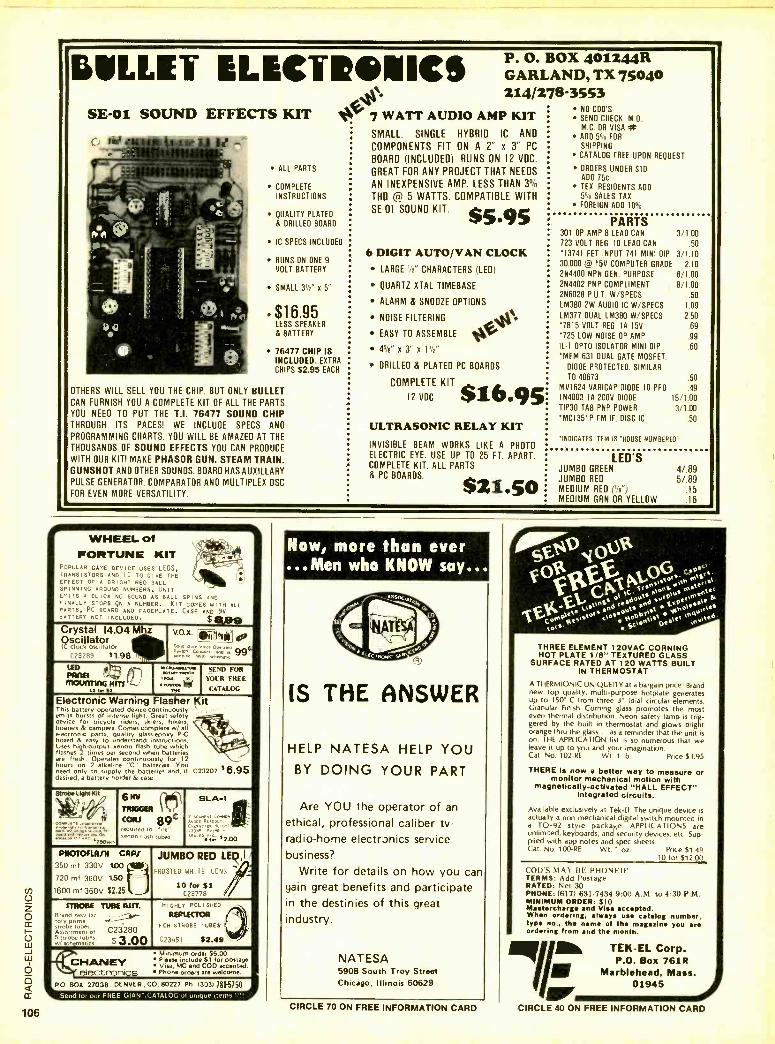
106
I
IULLEI ELECTRONICS 0-Nt.%:*WATT AUDIO AMP SE -01 SOUND EFFECTS KIT
P. O. BOX 401244R GARLAND, TX 75040 214/278 -3553
ALL PARTS
COMPLETE INSTRUCTIONS
QUALITY PLATEO
& DRILLED BOARD
IC SPECS INCLUDED
RUNS ON ONE 9-
VOLT BATTERY
SMALL 3!h" x 5"
e $16.95 LESS SPEAKER
& BATTERY
76477 CHIP IS INCLUDED. EXTRA
CHIPS 52.95 EACH
OTHERS WILL SELL YOU THE CHIP. BUT ONLY BULLET CAN FURNISH YOU A COMPLETE KIT OF ALL THE PARTS
YOU NEED TO PUT THE T.I. 76477 SOUND CHIP THROUGH ITS PACES! WE INCLUDE SPECS AND
PROGRAMMING CHARTS. YOU WILL BE AMAZED AT THE
THOUSANDS OF SOUND EFFECTS YOU CAN PRODUCE
WITH OUR KIT! MAKE PHASOR GUN. STEAM TRAIN. GUNSHOT AND OTHER SOUNDS. BOARD HAS AUXILLARY PULSE GENERATOR. COMPARATOR AND MULTIPLEX OSC
FOR EVEN MORE VERSATILITY.
KIT SMALL. SINGLE HYBRID IC AND
COMPONENTS FIT ON A 2" x 3" PC
BOARD (INCLUDED). RUNS ON 12 VDC.
GREAT FOR ANY PROJECT THAT NEEDS
AN INEXPENSIVE AMP. LESS THAN 3 °/D
THD @ 5 WATTS. COMPATIBLE WITH
SE -01 SOUND KIT. s 5.95 6 DIGIT AUTO /VAN CLOCK
LARGE '7" CHARACTERS (LEDI
QUARTZ XTAL TIMEBASE
ALARM & SNOOZE OPTIONS
NOISE FILTERING
EASY TO ASSEMBLE
45 /2" x 3"
DRILLED & PLATEO PC BOARDS
COMPLETE KIT
12 VDC $16.9 ULTRASONIC RELAY KIT INVISIBLE BEAM WORKS LIKE A PHOTO ELECTRIC EYE. USE UP TO 25 FT. APART. COMPLETE KIT. ALL PARTS & PC BOARDS.
$21.50
NO COOS
SEND CHECK. M.O..
M.C. OR VISA it ADO 5a'ó FOR
SHIPPING
CATALOG FREE UPON REQUEST
ORDERS UNDER SID ADO 75c TEX. RESIDENTS ADO
5% SALES TAX FOREIGN ADD 10°',
PARTS 301 OP AMP 8 LEAD CAN 3/1.00 723 VOLT REG. 10 LEAD CAN .50
13741 FET INPUT 741 MINI DIP 3/1.10 30.000 @ 15V COMPUTER GRADE 2.10 2N4400 NPN GEN. PURPOSE 8/1.00 2N4402 PNP COMPLIMENT 8/1.00 2N6028 P.U.T. W /SPECS .50
LM380 2W AUDIO IC W /SPECS 1.09
LM377 DUAL LM380 W /SPECS 2.50
'7815 VOLT REG. IA 15V .69
'725 LOW NOISE OP AMP .99
IL -1 OPTO ISOLATOR MINI DIP .60
*MEN 631 DUAL GATE MOSFET.
DIODE PROTECTED. SIMILAR TO 40673 50
MV1624 VARICAP 010DE 10 PFD .49 IN4003 lA 200V 0100E 15/1.00 TIP30 TAB PNP POWER 3/1.00 'MCI351P FM IF DISC IC 50
'INDICATES ITEM IS "HOUSE NUMBERED"
LED'S JUMBO GREEN
JUMBO RED
MEDIUM RED ('é ") MEDIUM GRN OR YELLOW
4/.89 5/.89
15
16
i
+ WHEEL of 1t
FORTUNE KIT e- POPULAR GAME DEVICE USES LEDS, TRANSISTORS AND IC TO GIVE THE EFFECT OF A BRIGHT RED BALL SPINNING AROUND NUMBERS. UNIT EMITS A CLICKING SOUND AS BALL SPINS AND FINALLY STOPS GN A NUMBER. HIT COMES WITH ALL PARTS, PC BOARD ANO FACEPLATE. CASE AND 9V BATTERY NOT INCLUDED. $ 1199 Crystal 14.04 Mhz Oscillator IC clock oscillator
C23?" $1.98
V.O.X. la. sa,e
wW
na +C m 99`^1 "Hn, w ,. ..m.,. 9
LEA }) 16 HITS , A
p,= ,A',
.. ..MK rye MK
SEND FOR
YOUR FREF:
CATALOG
Electronic Warning Flasher Kit This battery operated device continuously '
emits bursts of intense light. Great safety -4 device for bicycle riders, skiers, hikers, boaters & campers. Comes complete w/ all t / electronic parts, quality glass -epoxy P-C. board & easy to derstantl instructions. Uses high-output xenon flash tube which V, flashes 2 times per second when batteries are fresh. Operates continuously for 12 hours on 2 alkaline "C" batteries. You need only to supply the batteries and, if C23207 $6.95 desired, a battery holder & case.
Strobe LipMK I
COMPLETE 0.../^tt'
'ago.-
M I 6 1 .-
TRIGGER 19
required to -fire ..flan flash t,,I,e
SLA -1
. .
ro. s2.00
PNOTOFLNR OW 350 mt 330V 100
720 mf 360V 1.50
1600 mf 360V $2.25
JUMBO RED LEDII
FROSTED WHITE LEN'S
10 for 023778
STROBE 1118E R1.-" Brand
prime new la< -
m- ó t. be tubes.
Assortment of 023280 Ñsts strobe tubes, $3.00 hgmancs
CHLY POL SHED
REFLECTOR r
, oR STROBE TUBES ¡ .[3451 $2.49 J
4 Minimum order $5.00
NANEY Please include for posted. Visa, MC and COO D accepted.
electronics Phone orders are welcome.
O BOX 27038, DENVER. CO. 80227 Ph 13031781 -5750 a. 2l @IReP \ /q[
Now, more than ever ...Men who KNOW say...
IS THE ANSWER
HELP NATESA HELP YOU BY DOING YOUR PART
Are YOU the operator of an
ethical, professional caliber tv- radio -home electr3nics service business?
Write for details on how you can gain great benefits and participate in the destinies of this great industry.
NAT ESA 5908 South Troy Street Chicago, Illinois 60629
CIRCLE 70 ON FREE INFORMATION CARD
THREE ELEMENT 1 20VAC CORNING HOT PLATE 1/8 " TEXTURED GLASS
SURFACE RATED AT 120 WATTS BUILT IN THERMOSTAT
A THERMIONIC UNIQUEITY at a bargain price! Brand new top quality, multi -purpose hotplate generates up to 150° C from three 3" (dia) circular elements. Granular Finish Corning glass promotes the most even thermal distribution. Neon safety lamp is trig- gered by the built in thermostat and glows bright orange thru the glass... as a reminder that the unit is on. THE APPLICATION list is so numerous that we leave it up to you and your imagination. Cat. No. 102 -RE Wt. 1 lb. Price $3.95
THERE is now a better way to measure or monitor mechanical motion with
magnetically- activated "HALL EFFECT" Integrated circuits.
Available exclusively at Tek -El. The unique device is actually a non -mechanical digital switch mounted in a TO -92 style package. APPLICATIONS are unlimited, keyboards, and security devices, etc. Sup- plied with app notes and spec sheets. Cat. No. 100 -RE Wt. 1 oz. Price $1.49
10 for $12.00
('VU'S MAY HE PHONED' TERMS: Add Postage RATED: Net 30 PHONE: (617) 631 -7434 9:00 A.M. to 4:30 P.M. MINIMUM ORDER: $10 Mastercharge and Visa accepted. When ordering, always use catalog number, type no., the name of the magazine you are ordering from and the month.
TEK -EL Corp. P.O. Box 761R
Marblehead, Mass. 01945 J
CIRCLE 40 ON FREE INFORMATION CARD
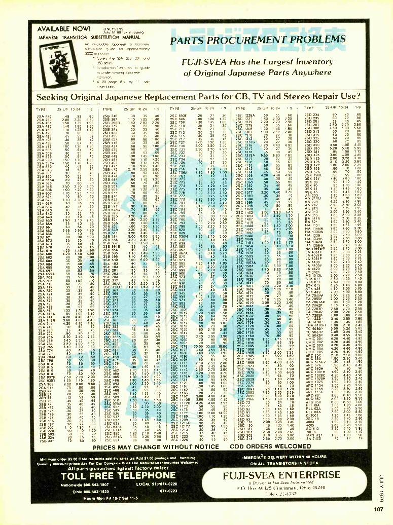
AVAILABLE NOW! ONLY5395 Add 51.00 for shipping
JAPANESE TRANSISTOR SUBSTITUTION MANUAL
An involuoble Joponese ro J0000658
substitution guide for oppro.inorefy 3000 rronsiítors
Covers the 25A 253 25C and 25D series
Inrroducnon' includes o guide ro undersrondrng Japanese rronsrsron
A 90 poge 8'y by 11 of cover book
PARTS PROCUREMENT PROBLEMS
FUJI -SVEA Has the Largest Inventory of Original Japanese Parts Anywhere
Seeking Original Japanese Replacement Parts for CB, TV and Stereo Repair Use? TYPE 25-UP 10-24 1-9 TYPE
2SA 473 .45 .55 .60 2SB 346 2SA 483 2.00 2.20 2.50 2SB 367 2SA 484 1.50 1.75 1.95 2SB 368B 2SA 485 1.40 1.60 1 80 2SB 379 2SA 489 1 10 1.25 1 40 2S8 381 2SA 490 70 .80 .90 2SB 400 2SA 493 .45 .53 .59 258 405 2SA 495 30 35 40 256 407 2SA 496 .50 .64 70 2SB 415 2SA 497 1.00 1.20 1.30 2S8 434 2SA 505 .50 .64 .70 2SB 435 2SA 509 30 35 40 2SB 440 2SA 525 .50 .64 70 258 449 2SA 530 1.50 1.70 1 90 2SB 461 2SA 537A 1.50 1 70 1.90 2SB 463 2SA 539 40 45 50 2SB 471 2SA 545 45 53 59 2SB 472 2SA 561 .30 .35 .40 2SB 473 2SA 562 30 35 .40 2SB 474 2SA 564A .20 27 .30 2S8 481 2SA 565 .70 80 90 2SB 492 2SA 566 2.50 2.70 3.00 2S6 507 2SA 606 1.00 1.20 1.30 2SB 509 2SA 607 1.10 1.25 1 40 258 511 2SA 624 70 80 .90 2S8 514 2SA 627 3.10 3.30 3.60 2S8 523 25A 628 .30 35 40 2SB 526C 2SA 634 .40 .45 .50 2SB 527 2SA 640 .30 .35 .45 2S6 5280 2SA 642 .30 .35 .40 2SB 529 2SA 643 .30 .40 .45 256 530 2SA 653 1.90 2.10 2.40 2SB 531 2SA 659 .35 .40 .45 2SB 536 2SA 661 .50 -64 .70 258 537 25A 663 3.65 3.80 4.20 2SB 539 2SA 666 .35 .40 .45 2SB 541 2SA 671 .80 .90 1.00 2SB 554 2SA 672 .30 .35 .40 2S8 556 2SA 673 .35 .40 .45 2SB 557 2SA 678 .35 .40 .45 2SB 5618 2SA 679 4.20 4.40 4.90 2SB 564 2SA 680 4.20 440 4.90. 2SB 595 2SA 682 .80 90 1.00 2SB 596 2SA 683 .30 35 .40 2SR 600 2SA 684 .35 40 .45 25C 183 2SA 695 .40 53 .59 2SC 184 2SA 697 .40 .53 .59 2SC 281 2SA 699A .50 .64 70 2SC 283 2SA 705 .40 .53 .59 2SC 284 2SA 706 .85 1.00 1.10 2SC 317 2SA 715 .60 .70 .80 2SC 352A 2SA 719 .30 .35 .40 2SC 353A 2SA 720 .30 .35 .40 2SC 367 2SA 721 .30 .35 .40 2SC 369 2SA 725 .30 .35 .40 2SC 370 2SA 726 .30 .35 .40 2SC 371 2SA 733 .20 .27 .30 2SC 372 2SA 738 .40 .53 .59 2SC 373 2SA 740 1.50 1.70 1.90 2SC 374 2SA 743A .85 1.00 1.10 2SC 375 2SA 744 4.20 4.40 4.90 2SC 377 2SA 745R 3.80 4.00 4.40 2SC 380 2SA 747 4.20 4.40 4.90 25C 381 2SA 748 .70 .80 .90 2SC 382 2SA 750 .35 .40 .45 2SC 383 2SA 755 .80 .90 1.00 2SC 387A 25A 756 2.30 2.40 2.65 25C 388A 2SA 758 3.40 3.55 3.90 2SC 394 2SA 764 3.80 4.00 4.40 2SC 403 2SA 765 3.10 3.30 3.60 25C 430 2SA 774 40 45 .50 2SC 454 2SA 777 50 .64 .70 2SC 458 2SA 794A 60 .70 .80 2SC 460 2SA 798 50 55 60 2SC 461 2SA 814 70 .80 .90 2SC 478 2SA 815 60 .70 80 2SC 481 2SA 816 50 64 70 2SC 482 2SA 818 70 .80 .90 2SC 484 2SA 837R 2.50 2.70 2.90 2SC 485 2SA 839T 1.30 1.45 1.60 2SC 486 2SA 908 8.60 8.80 9.80 2SC 493 2SA 913 .70 .80 .90 2SC 495 2SB 22 .30 35 40 2SC 496 2S8 54 .20 27 .30 2SC 497 2SB 55 .40 .53 .59 2SC 509 2SB 75 .35 40 45 2SC 510 2S8 77 .35 40 45 2SC 515A 2SB 173 .30 .35 40 25C 517 2SB 175 .20 .27 30 2SC 535 2SB 176 .30 .35 .40 2SC 536 2SB 178 .35 .40 45 2SC 537 2SB 186 .20 .27 .30 2SC 627 2SB 187 .20 27 .30 2SC 631
2SB 202 1.10 1.20 1.30 2SC 632A 258 220 .90 1 10 120 2SC 634A 2SB 303 .30 .35 40 2SC 680 2SB 324 .30 .35 40 2SC 681A 2S8 337 70 80 90 2SC 684
PRICES MAY CHANGE WITHOUT NOTICE COD ORDERS WELCOMED
25-UP 10-24 1.9 TYPE 25-UP 10-24 1-9 TYPE 25-UP 10-24 1-9 TYPE 25-UP 10-24 1-9
30 40 2SC 693F 20 .27 .30 2SC 1226A 50 55 60 2SD 234 .60 .70 .80
1 10 .35
1.25 1.40 2SC 696 1 00 1 20 1.30 2SC 1237 1.80 2.00 2.25 2SD 235 .60 .70 .80
1.80 2.00 2 25 2SC 708 1 30 1 45 1 60 2SC 1239 2.20 2.70 2.90 2SD 261 .35 .40 .45
70 80 90 2SC 710 20 .27 30 2SC 1279 50 55 .60 2SD 287 2.50 2.70 2.90
30 35 40 2SC 711 20 .27 30 2SC 1306 1.30 1 45 1 60 2S0 300 4.50 5.00 5.60
30 35 40 2SC 712 20 27 30 25C 1307 1.90 2.10 240 2SD 313 .60 .70 .80
30 .35 40 2SC 715 30 35 40 2SC 1310 20 27 30 2SD 315 .60 70 .80
80 .90 1.00 2SC 717 35 40 45 2SC 1312 20 27 30 2S0 325 60 60 70 .80
30 35 40 2SC 727 700 1.20 1.30 25C 1313G 20 27 30 250 330 70 .80
80 90 1 00 2SC 730 3 00 3.20 3.40 2SC 1316 4 20 4 40 4.90 2S0 350 3.80 4.06 4.40
90 1 10 1 20 25C 731 2 50 2.70 2 90 2SC 1317 20 27 30 2SD 380 5.20 5.40 5 95 40 53 2SC 732 20 27 30 2SC 1318 35 40 45 2S0 381 .85 1.00 1.10
1 30 1 45 .59
1 60 2SC 733 20 27 30 2SC 1325A 6.50 6 90 7 60 2SD 424 3.80 4.00 4.40 .90 1.10 1 20 2SC 734 20 27 30 2SC 1327 20 27 30 2SD 425 2.90 3.20 3.40 90 1.10 1 20 2SC 735 20 27 30 2SC 1330 50 55 60 2S0 426 3.10 3.30 3.60
1 10 1 25 1 40 256 738 .20 27 30 2SC 1335 50 55 60 2S0 427 1.80 2.00 2.25 2 10 2.50 2.80 2SC 756 1:50 1 80 2.00 2SC 1342 45 53 59 2SD 525 .90 1 10 1 20
.80 90 1.00 25C 756A 1.50 1 80 2.00 2SC 1344 .45 53 59 250 526 60 70 .80
.70 80 90 2SC 763. 35 40 45 25C 1358 4.20 4 40 4.90 25K 19BL .50 .55 .60
90 1.10 1 20 25C 772 .30 35 .40 2SC 1359 .30 35 .40 3SK 22Y 1.40 1.60 1.80
60 70 80 250 773 .35 40 .45 2SC 1360 .50 .55 .60 3SK 39 .90 1 10 120 80 90 1 002S 774 1.00 1 20 1.30 2SC 1362 .35 .40 45 3SK 40 .90 1 10 1 20
1 10 70
1 20 80
1 30 90
2SC 775 2SC 776
1.40 2.00
1.60 2.20
1.80 2.50
25C 1364 25C 1377
35 3.20
.40 3.40
.45 3.70 3S
1.30 1.30
1.45 1 45
1.60 1.60
90 2SC 777 3.00 3.25 3.50 25C 1383 .30 35 40 A 1 40 1 60 1.80 .70 .70
.80 80 90 2SC 778 2.90 3.20 3.40 25C 1384 .35 .40 45 AN 2140 1.50 1 70 1.90
70 90 2SC 781 1 90 2.10 2.40 2SC 1396 45 53 59 AN 239 4.20 4.40 4.90
90 .80
1.10 1 20 2SC 783 2.10 2.50 2.80 2SC 1398 .70 80 90 AN 247 2.50 2.70 3.00
90 25C 784 30 35 .40 2SC 1400 35 40 45 AN 274 1.50 1.75 1 95 .70 .70
.80
.80 .90 2SC 785 35 40 45 2SC 1402 3.00 3.20 3.40 AN 313 3.00 3.20 3.40 3.20 340 3.70 2SC 789 80 90 1 00 25C 1403 3.20 3.40 3.70 AN 315 1.80 2.00 2.25 1.80 2 00 2.25 2SC 790 .80 90 1 00 2SC 1407 .50 .55 .60 BA 511A 1.80 2.00 2.25 1.00 1 20 1.30 2SC 793 2 00 2.20 2.50 2SC 1419 .60 .70 .80 BA 521 1.90 2.10 2.40 1.00 1 20 1.30 2SC 799 2.00 2.20 2.50 2SC 1444 1.60 1.80 2.00 HA 1151 1.50 1.75 1 95
3.20 340 3.70 25C 828 .20 .27 .30 2SC 1445 2.50 2.70 2.90 HA 1156W 1.60 1.80 2.00 3.20 3.40 3.70 2SC 829 .20 .27 .30 2SC 1447 .60 .70 .80 HA 1306W 2.00 2.20 2.50 600 6.00 6 60 2SC 830H 2.50 2.70 3.00 2SC 1448 .70 .80 .90 HA 1339 2.50 2.70 3.00
3.20 3.40 3 70 2SC 838 35 .40 45 2SC 1449 .60 .70 .80 HA 1339A 2.50 2.70 3.00 2.10 2.50 2.80 2SC 839 .30 .35 .40 2SC 1451 1.00 1.10 1.20 HA 1342A 2.50 2.70 3.00
.35 40 .45 2SC 853 .80 .90 2SC 1454 3.20 3.40 3.70 HA 1366W 2.50 2.70 3.00 .59 2SC 867
.70 3.20 3 40 3.70 2SC 1475 .80 90 1 00 HA 1366WR 2.50 2.70 3.00 .40
1.10 .53
1.40 1.50 2SC 867A 3.20 3 40 3.70 2SC 1478 .50 55 .60 LA 4031P 1.80 2.00 2.25
1.10 1.40 1.50 2SC 870 35 40 45 2SC 1509 .50 .55 .60 LA 4032P 1.80 2.00 2.25 5.00 6 00 6.60 2SC 871 35 .40 .45 2SC 1567 .60 .70 .80 LA 4051P 1.80 2.00 2.25
.40 59 2SC 895 4.20 4 40 4.90 2SC 1567A .60 70 .80 LA 4400 1.90 2.10 2.40 .53 .53 59 2SC 897 2.00 2.20 2.50 2SC 1584 6.00 6.30 7.00 LA 4400Y 2.00 2.20 2.50 .40
2SC 898 2.50 2.70 3.00 2SC 1586 6.50 6.90 7.60 LA 4420 2.00 2.20 2.50 .30 .35 .53
.40 .59 2SC 900 20 .27 .30 2SC 1624 .60 70 .80 LD 3001 2.00 2.20 2.50
.40 1 00 2SC 923 20 27 30 2SC 1626 60 .70 80 M5 1513L 2.00 2.20 2.50 .80 .90
.53 .59 2SC 929 .20 27 30 2SC 1628 60 70 .80 STK 011 3.80 4.00 4.40 .40 2.00 2.20 2.50 2SC 930 .20 .27 30 2SC 1647 70 .80 .90 STK 013 7.60 8.00 8.80
1.40 1.60 1 80 2SC 941 .20 .27 .30 2SC 1667 3.00 3.20 3 40 STK 015 4.20 4.40 4.90
.70 .80 2SC 943 .35 .40 45 2SC 1669 .90 1.00 1 10 STK 435 4.50 5.00 5.60 .60 .30 .35 .40 2SC 945 .20 .27 30 2SC 1674 30 35 .40 STK 439 7.90 8.00 8.80
.30 2SC 959 1.00 1.20 1 30 2SC 1675 20 27 .30 TA 7045M 2.00 2.20 2.50 .20 .27 .35 .40 2SC 971 70 .80 .90 2SC 1678 1 10 1.25 1_40 TA 7055P 2.00 2.20 2.50 .30
.30 2SC 982 70 80 .90 2SC 1679 3.00 3.20 3.40 TA 7061AP .90 1.10 1.20 .20 .27
.27 .30 2SC 983 .50 .64 .70 2SC 1681 .30 .35 .40 TA 7062P 1.10 1.25 1.40 .20
.35 .40 2SC 1000 .35 .40 45 2SC 1682 .30 .35 .40 TA 7203P 2.50 2.70 2.90 .30 30 .35 40 2SC 1012 1.20 1.40 1 50 2SC 1684 .30 .35 40 TA 7204P 2.00 2.20 2.50
40 2SC 1013 50 .64 70 2SC 1687 .40 .45 .50 TA 7205P 1.60 1.80 2.00 .30 20
.35
.27 .30 2SC 1014 .50 .64 70 2SC 1688 .35 .40 .45 TA 7222P 3.40 3.55 3.90
.40 45 2SC 1017 .80 90 1 00 2SC 1708 30 .35 .40 TA 7310P 1.30 1.45 1.60 .35 35 40 45 2SC 1018 60 70 80 2SC 1728 70 .80 90 TBA 810SH 1.90 2.10 2.40 15 40 45 2SC 1030 1 80 2 10 2.40 25C 1730 .45 .53 59 TC 5080P 5.00 5.20 5.80
35 .40 45 2SC 1047 .35 40 .45 25C 1756 50 55 60 TC 5081P 3.00 3.20 3.40
40 53 .59 2SC 1051 3.40 3.55 3.90 2SC 1760 .70 .80 90 TC 5082P 3.40 3.55 3.90
.20 27 .30 2SC 1060 70 80 90 2SC 1816 1.50 1.75 1.95 UHIC 001 4.20 4.40 4.90
.30 35 .40 2SC 1061 70 80 90 2SC 1856 .45 53 .59 UHIC 002 4.20 4.40 4.90
50 64 .75 2SC 1076 30.00 35.00 39.00 2SC 1885 .45 53 .59 UHIC 003 4.20 4.40 4.90
.30 35 .40 2SC 1079 3 40 3.55 3.90 2SC 1908 .30 35 .40 UHIC 004 4.20 4.40 4.90
.20 27 30 2SC 1080 3 40 3.55 3 90 2SC 1909 1 80 2.00 2.25 UHIC 005 4.20 4.40 4.90
35 40 45 2SC 1096 .45 55 60 2SC 1945 4.50 5.00 5.60 uPC 20C 2.10 2.50 2.80 35 40 45 2SC 1098 50 64 70 2SC 1957 60 .70 .80 uPC 563 1.90 2.10 2.40
70 80 - 2SC 1111 2 10 2 50 2.80 2SC 1969 3.60 4.00 4.40 uPC 575C2 1.30 1.45 1.60 .60
1.30 1.40 1 50 2SC 1114 '4.20 4.40 4.90 2SC 1973 .70 .80 .90 uPC 576 1.90 2.10 2.40
1 10 1 25 1.40 2SC 1115 2.50 2 70 3.00 2SC 1975 1.30 1.70 1.90 uPC 592H .70 .80 .90
1 30 1.40 1 50 2SC 1116 3.20 3 40 3.70 2SC 1978 5.40 6.00 6.60 uPC 1001H 1.90 2.10 2.40
1 30 1.40 1 50 2SC 11160 3.40 3 55 3.90 2SC 2028 .50 .64 .70 uPC 1008C 4.20 4.40 4.90
1.30 1.40 1 50 2SC 1124 .80 90 1.00 2SC 2029 1.50 1.80 2.00 uPC 1020H 1.90 2.10 2.40
3.00 3.20 3.40 2SC 1127 80 90 1.00 2SC 2074 .80 .90 1.00 uPC 1025 1.90 2.10 2.40
.45 55 60 2SC 1161 1 30 1 45 1.60 2SC 2076 .50 .64 .70 uPC 1154 2.00 2.20 2.50
.45 55 60 2SC 1162 70 .80 .90 2SC 2091 .90 1.10 1.20 uPC 1155 2.00 2.20 2.50
1 10 1 25 1 40 2SC 1166 .20 .27 .30 2SC 2092 1.80 2.00 2.25 uPC 1156 1.90 2.10 2.40 40 45 2SC 1167 3.80 4.00 4.40 2SC 2098 3.20 3.40 3.70 uPD 861 8.00 8.40 9.50 .35
1.30 1-40 1 50 2SC 11708 3.80 4.00 440 2SC 2166 1.40 1.60 1.80 uP0 857 8.00 8.40 9.50
80 .90 1.00- 25C 1172B 3.20 3-60 3.95 2S0 72 .50 .64 .70 uPD 858 6.00 6.30 7.00
2 50 2.70 3.00 2SC 1173 50 .55 .60 2SD 77 .35 .40 .45 PLL OIA 3.00 4.20 4.60
.30 .35 .40 2SC 1175 35 40 45 2SD 90 1.30 1.45 '1.60 PLL 02A 5.00 5.20 5.90
.30 .35 .40 2SC 1177 11 00 1260 14.00 2SD 91 1.30 1.45 1.60 PLL 03A 7.60 8.00 8.80
30 .35 40 25C 1189 1 00 1.10 1.20 2S0 92 1.30 1.45 1.60 C-3001 1.30 1.45 1.60 1 30 1 45 1.60 25C 1209 30 35 40 25D 93 1.60 1.80 2.00 2SC FB 2.20 2.70 2.90
35 40 45 2SC 12110 30 35 .40 2S0 118 2.90 3.20 3.40 4004 1.90 2.10 2.40
35 40 45 25C 1212A 80 90 1.00 2S0 130 1.10 1.25 1.40 4005 2.00 2.20 2.50 35 40 45 2SC 1213 .30 35 .40 2S0 187 .35 .40 .45 SG 613 5.20 5.40 5.95
1.90 2 10 2 40 2SC 1215 35 40 45 2SD 201 2.30 2.40 2.65 78L05 .90 1.00 1 10
3.00 3 25 3 50 2SC 1222 20 27 .30 2SD 202 3.40 3.55 3.90 MPS U31 1.50 1.70 1 90
80 90 100 2SC 1226 50 55 60 2SD 218 2.50 2.70 3.00 SN 7400 15 17 19
Minimum ord., 95 00 OhIo residents add 41. sales tes Add SI 00 posl.pir and handling
Ounllty discount prit.. Ask For Our ComplN. Price List Manufacturer inquiries Welcomed
All parts guaranteed against factors' defect
TOLL FREE TELEPHONE Nationwide 800543.1807
Ohio BOO 582 -1630
LOCAL 5137874 -0220
874 -0223
Hours Mon Fn 10 -7 Set 11 -6
IMMEDIATE DELIVERY WITHIN 48 HOURS
ON ALL TRANSISTORS IN STOCK
FUJI -SVEA ENTERPRISE a Division of Futl Suea Incorporated
P.O. Box 40325 Cincinnati, Ohio 95240
Telex 21 -4732

6 o rr
108
1I II 1II II ...n WE'VE
THAT GO T THE BUG,
le, By now you've probably M read the article in June issue
of Kilobaud about Motorola's new fantastic Miro Chroma 68.
It is the latest in TV Bugs which enables you to hook up directly to your own standard color TV with the fewest of parts
Micro Chroma 68 kit includes: MC1372 -Color TV video modulator.
IMC6821- Peripheral interface adapter. MC6808- Microprocessor with clock. MC6846- Rom -I /O- Timer. MC6847 -Video display generator. MC6850- Asynchronous communications _ interface adapter. . Also includes printed circuit board and data sheets on all above mentioned LSI.
1
1 I
1 It
1
MICRO
CH A
MOTOROLA 5 MICROPROCESSOR 70 COLOR TEtEV /SION
INTERFACE CHIP SET
wart Tv BUG
/29.95
AND WE'VE GOT
IN STOCK AND NOW AVAILABLE THROUGH AUSTIN ELECTRONICS.
THE PARTS KIT! We at Austin Electronics went one further and put together a parts kit of all support devices. These parts for the average enthusiast would be very diffr cult to find and expensive. We've made - it easy and substantially less expensive.
Bug kit II comes complete with all coin. ponants necessary for on board operation Including 161 2114 rams.
BUG KIT II $149.95 jj MICRO CHROMA 68 KIT $129.95 PC BOARD SEPARATE $45.00 - ADDITIONAL 2114 RAMS $8.50 BUY THE MICRO CHROMA 68 AND THE BUG KIT 11 NOW SAVE $15.00.
SEND FOR OUR NEW CATALOG 1. " - WHICH INCLUDES GREAT BARGAINS El ON ASCII KEYBOARDS, MODEMS, - COMPUTER POWER SUPPLIES, ETC.
I AUSTIN ELECTRONICS MII Il 1536 EAST ANDERSON LN. TERMS: Check or money order, SUITE E NO COD's. Texas residents add AUSTIN, TEXAS 78752 5% sales tax. Overseas countries Ell
1512- 83E-9677 add $5.00 for surface rates. - r
gE Il II II IU__11
CIRCLE 35 ON FREE INFORMATION CARD
I.- 1,000 Electricity from the sun GIANT 31/2 inch cell, delivers 1 amp $8.50 Giant cell w /special motor & propellor $10.25
SOLID STATE power supply 12 VDC 15 amp $40.00 SOLID STATE power supply 5 VDC 35 amp $50.00 Above supplies unused in original cartons. Operate from 115 volts AC 60 cycle. Made for computer work. Solid state, filtered, regulated, over voltage protected.
ULTRASONIC room alarm, intrusion detection with full data for hookup $40.00
SEE IN THE DARK IR viewer complete ready to operate. Guaranteed by the manufacturer. Portable, runs on lantern battery. New, see in total darkness. No shipments to Calif. Comes complete with built in IR source and adjustable focus lens.
SPL -21 $199.00
All items FOB Lynn, Mass. Send for free 72 page catalog jam packed with goodies. Micro Processor Power Supplies
Brand New 60% Discount. Send for List.
Meshna Inc., PO Box 62, E. Lynn, Mass. 01904
CIRCLE 43 ON FREE INFORMATION CARD
Test LEADER Instents
OSCILLOSCOPES
MODEL L8PSax
The 30 MHz Dual Trace Oscilloscope with Delay
5mV sensitivity. Built -in delay line. Single shot trigger (CH -1, CH -2). 5" P -D -A CRT assures brighter, sharper trace. 20 nS/cm sweep capability plus 11.7 nSec rise time.
LIST PRICE: $1050 OUR PRICE:$888
MODEL LB0515 LIST PRICE: $1395 OUR PRICE:$1180
25 MHz Dual Trace, Oscilloscope Delayed Sweep
Sweep delay, continuously variable from 1 uSec to 5 Sec. 5 mV /Div. Vertical Sensitivity with x 3% ecc. Rectangular CRT with internal graticule. 14 nSec rise time. CH -1 or 2 trigger; HF filter; and TV sync.
MODEL LeP50a
The 20 MHz Dual Trace Oscilloscope
Add 8 subtract modes (with CH -2 invert). Front panel kV operation. 17.5 nanosec rise time. Automatic trigger from either channel, including TV sync. 10 mV sensitivity.
LIST PRICE $769 OUR PRICE:s635 The 20 MHz Single Trace Triggered Oscilloscope
Outstanding trigger sensitivity over entire operational range. 10 mV sensitivity and 17.4 nSec rise time. X5 magnification (í55/e) delivers 100 nS/cm maximum speed for easy, precise readings.
LIST PRICE: $549 OUR PRICE:s455
FLUKE
8022A
NEW DIGITAL MULTIMETERS
10,000 MC resistance meas with conductance function Extensive overload and transient protection Rugged construction - MIL -T -28800 Hi /Lo power ohms for in- circuit resistance and diode testing 10 MO input impedance doesn't load circuit 200 hour battery life - low battery indicator Large LCD readout - 2000 counts 1 year calibration cycle - only 3 adjustments One -hand operation
OUR PRICE: $129
8010A OUR PRICE s239
8012A
OUR PRICE $299
Large 31/2-Digit LCD's - view in any light Conductance function - resistance to 10,000 MO AC measurements to 50 kHz and higher True RMS for ac accuracy Touch -Hold probe for tricky places (Y8008) Diode test and low power ohms One year accuracy reduces calibration costs COMMON floatable to 500V Recessed jacks reduce shock hazard Current mode fuse protection to 600V Voltage mode transient protection to 6 kV Autozero and autopolarity AC or dc current to 10 amps with 8010A Resistance resolution to 0.0010 with 8012A Built -in batteries and charger (Option -01) Rugged enough for field or bench
SEND FOR OUR CATALOG
Call TOLL FREE- N.J. CALL:
18001526-2514.-12011227-7720
AMPOWER INST., INC. 26 JUST ROAD, FAIRFIELD, N. J. 07006
THE MEASUREMENT SPECIALISTS "WE SERVICE WHAT WE SELL"
41110 Mastercharge
Bankamericard
FREE and
COD Accepted TEST LEADS add 53.00 to
WITH EVERY cover shipping
ORDER handling insurance
N.J. res. add
CALL 5% tax.
TODAY
CIRCLE 66 ON FREE INFORMATION CARD

S -100 Computer Boards 8K Static RAM Kit Godbout $135.00
16K Static RAM Kit 265.00
24K Static RAM Kit 423.00
32K Dynamic RAM Kit 310.00 64K Dynamic RAM Kit 470.00
8I016K Eprom Kit (less PROMS) $89.00 Video Interface Kit 5139.00 Motherboard S39. Extender Board 58.99
P.O. Box 4430E Santa Clara, CA 95054
For will call only (408) 988 -1640
2322 Walsh Ave.
RCA Cosmac Super Elf Computer $106.95 Compare features before you decide to buy any
other computer. There is no other computer on
the market today that has all the desirable bene- fits of the Super Elf for so little money. The Super Elf is a small single board computer that does
many big things. It is an excellent computer for training and for learning programming with its
machine language and yet it is easily expanded with additional memory, Tiny Basic, ASCII Keyboards, video character generation, etc.
The Super Elf includes a ROM monitor for pro- gram loading, editing and execution with SINGLE STEP for program debugging which is not in- cluded in others at the same price. With SINGLE STEP you can seethe microprocessor chip opera- ting with the unique Quest address and data bus displays before, during and after executing in-
structions. Also. CPU mode and instruction cycle are decoded and displayed on eight LED indicator lamps.
An RCA 1861 video graphics chip allows you to
connect to your own TV with an inexpensive video modulator to do graphics and games. There is a
speaker system included for writing your own music or using many music programs already written. The speaker amplifier may also be used
to drive relays for control purposes.
A 24 key HEX keyboard includes 16 HEX keys
plus load, reset, run, wait, input, memory pro-
Super Expansion Board with This is truly an astounding value! This board has
been designed to allow you to decide how you want it optioned. The Super Expansion Board comes with 4K of low power RAM fully address- able anywhere in 641( with built -in memory pro- tect and a cassette Interlace. Provisions have been made for all other options on the same board and it fits neatly into the hardwood cabinet alongside the Super EH. The board includes slots for up to 6K of EPROM (2708, 2758, 2716 or TI
2716) and is fully socketed. EPROM can be used for the monitor and Tiny Basic or other purposes.
A IK Super ROM Monitor $19.95 is available as
an on board option in 2708 EPROM which has
been preprogrammed with a program loader/ editor and error checking multi file cassette read /write software, (retocatible cassette tile) another exclusive f rom Guest. It includes register save and readout, block move capability and
video graphics driver with blinking cursor. Break
points can be used with the register save feature to isolate program bugs quickly, then follow with single step. The Super Monitor is written with subroutines allowing users to take advantage of
monitor functions simply by calling them up.
Auto Clock Kit $15.95 DC clock with 4-.50" displays. Uses National
MA -1012 module with alarm option. Includes kght dimmer, crystal timebase PC boards. Fully
regulated, comp. instructs. Add $3.95 for beau-
tiful dark gray case. Best value anywhere.
RCA Cosmac VIP Kit $229.00 Video computer with games and graphics. Fully assem. and test. $249.00
Not a Cheap Clock Kit $14.95 Includes everything except case. 2 -PC boards. 6-.50" LED Displays. 5314 clock chip, trans- former, all components and full instructions. Orange displays also avail. Same kit w /.80" displays. Red only. $21.95 Case $11.75
60 Hz Crystal Time Base Kit $4.40 Converts digital clocks from AC line frequency to crystal time base. Outstanding accuracy. Kit Includes: PC board, IC, crystal, resistors, ca-
pacitors and trimmer.
test, monitor select and single step. Large, on
board displays provide output and optional high
and low address. There is a 44 pin standard
connector for PC cards and a 50 pin connector for
the Quest Super Expansion Board. Power supply
and sockets for all IC's are included in the price
plus a detailed 127 pg. instruction manual which
now includes over 40 pgs. of software info. in-
cluding a series of lessons to help get you started
and a music program and graphics target game.
Remember, other computers only offer Super Elf
features at additional cost or not at all. Compare before you buy. Super Elf Kit $106.95, High
address option $8.95, Low address option $9.95. Custom Cabinet with drilled and labelled plexiglass front panel $24.95. NiCad Battery Memory Saver Kit $6.95. All kits and options also come completely assembled and tested.
Questdata, a 12 page monthly software publica- tion for 1802 computer users is available by sub-
scription for $12.00 per year
Attention Elf Owners New products in hardware and software coming soon.
Tiny Basic cassette $10.00. on ROM $38.00. original Elf kit board $14.95.
Cassette Interface $89.95 Improvements and revisions are easily done with
the monitor. If you have the Super Expansion Board and Super Monitor the monitor is up and
running at the push of a button.
Other on board options include Parallel Input and Output Ports with full handshake. They
allow easy connection of an ASCII keyboard to the
input port. RS 232 and 20 ma Current Loop for teletype or other device are on board and if you need more memory there are two S -100 slots for static RAM or video boards. A Godbout 8K RAM
board is available for $135.00. Also a 1K Super Monitor version 2 with video driver for full capa- bility display with Tiny Basic and a video interface board. Parallel I/O Ports $9.85, RS 232 $4.50, TTY 20 ma I/F $1.95, S -100 $4.50. A 50 pin connector set with ribbon cable is available at
$12.50 for easy connection between the Super Elf and the Super Expansion Board.
The Power Supply Kit for the Super Expansion
Board is a 5 amp supply with multiple positive and negative voltages $29.95. Add $4.00 for shipping. Prepunched frame $5.00. Case
$10.00. Add $1.50 for shipping.
Digital Temperature Meter Kit Indoor and outdoor. Switches back and forth. Beautiful. 50" LED readouts. Nothing like it
available. Needs no additional parts for corn - plete, full operation. Will measure -100' to +200"F, tenths of a degree, air or liquid. Very accurate. $39195 Beautiful woodgrain case w /bezel S11.75
NiCad Battery Fixer /Charger Kit Opens shorted cells that won't hold a charge
and then charges them up, all in one kit wlfull parts and instructions. $7.25
PROM Eraser Will erase 25 PROMS in
15 minutes. Ultraviolet, assembled $34.50
Rockwell AIM 65 Computer 6502 based single board with full ASCII keyboard
and 20 column thermal printer. 20 char. al-
phanumeric display. ROM monitor, fully expand- able. $375.00. 4K version $450.00. 4K Assem- bler $85.00, 8K Basic Interpreter $100.00. Power supply assembled in case $60.00.
TERMS: $5.00 min. order U.S. Funds. Calif residents add 6 %a tax. BankAmericard and Master Charge accepted. Shipping charges will be added on charge cards.
Same day shipment. First line parts only.
Factory tested. Guaranteed money back.
Quality IC's and other components at fac-
tory prices.
INTEGRATED CIRCUITS 7400771 74004 11 1M379M 500 74024 17 LM380N 1 D0
14044 19 04387 1.60 74094 23 164302 1 60 74104 17 1M7034 .40 74144 63 1147099 .28 74204 17 18472376W .50 74224 1,39 1641334 67 74304 20 1847410 35 74424 50 147116 25 14454 69 LM747HIN 62 74474 60 1647484 35 74484 69 LM73034 82 7404 17 1641304 1 10 74744 19 LM1305 , n 74754 49 14107 200 74854 88 1641310 74894 2 00 1841458 74904 43 1641800 74924 43 LM1812 74934 43 1641689 74954 69 1842111 741004 90 LM2902 741074 29 18439006 60 741214 34 LM3905 5 75
741234 59 LM309N el 741254 39 MC14589 50 741454 69 6E5504 65 741504 95 6E555V 43 741514 69 NE5564 79 7415414 100 14E5654 1 00 741574 69 4E5660 1 50 741614 87 65567V 1.20 747624 87 #65708 5.0 741634 87 NE5716 5.0 741744 96 78105 60 747754 90 78106 60 741904 115 79105 70 741924 87 781405 85 747934 85 75108 1.75 742214 155 7549104 50 742984 1 65 75492C4 55 74365N 95 75494CN 89 743666 95 743676 95
275 4
I I5 7 50
3 00 1 75 10
741800 ITL 1405006 14L026 1405046 7405056 1405086 1t15106
1513N 1413146 1415206 141322N f 4328 1415306 '1L533N '4LS38N 1405746 '4L5756 "41506 '4150N '4L5954 14051076 '415112N
L5113N 14051326 '4L5136N 14151516 '4451554 '+151576 '4151624 141016314 '41577011
4151906 '4152216 »1520M 14L5367N
LINEAR 143045 LA3046 CA3081 003082
03089 8301.46,411
161305H 043076 483086 0613099
193094 831106 LM317T6 18318 1M3206-5 1M5236-5 L93206-12 083201,15 163207-5 063207.8 043207.12 LM3207015 f 9324 143396 1M340K'9 L834069 483106.12 0613406.15 043406.24 L6340T-5 0834074 163407.12 183407-15 1M340T-18 LM340T-24
M313N 1830 I9370 11,c-
25 25 25
25
25
<9 90 25 25 41
39 30 15
47 51
51
1 89 35 35 35 72 35 67 67 67
91 91 I
1 95 67
1 35
90 67
I B0 90
2 95 35 87
35 89
A M 0 CONVERTER 80386 4.0 870000 13.95 87010M 1695 875007 1195 15130 9.95 9400009/6 7.40 1017103 9.50 1017107 1425 9702 77.95
CMOS C03401 Farr
00400 004001 004002 004006 C0401 004008 004009 004010 04017 CD4012 C04013 004014 C04015 CD4016 C04017 004018 004079 004025 004021 004022 C04023 004024 004025 04026 C04027 04028 C04029 C04030 04035 C04040 004042 04043 004044 004046 04049
5Ó 00405 90 004060 92 004066 35 004068 00 004069 95 C04070 O 04071 60 004072 60 04073 60 C04075 0 004076 60 04078
5 004001 55 004082 35 04116 35 C0440 35 C04507 35 04508 35 004510 25 004511 25 004515 25 C04516 25 04518 25 004520 25 C04527 50 004528 50 004553 15 CD4566 00 C04583
50 I6
21
21
39
21
C04585 0040192 74C0 7400/ 74010 74014 74020 74030 74048 74C74 74076 74090 74093 740154 740160 740175 740192 740221
740905
14C992 740922 740923 740925 740926 740927
INTERFACE 8095 8096 8097 8098 8309 BT10 13713
8720
9224
33
2,10
26
28 95 740 5
1.45 1.40 3.00 7.44 1 35 1.65 2.00 0
1 95 550 5.0 6.95 695 6 95
95 95 95 .95 25
4.0 3.00 50 310 3.50
8326 1.69 8728 2 .75 8797 1.69 8798 1.69
MOSIIMEMORY RAM 21011 3 95
2102411.4 7 60 21102.1 I IB 21902 I.25 2104A-4 1 95
1t81 3 95 2112.2 3 95
21111-3 ".75 4116 13 .95 251 6 30
M5262 40 MM5260 30 MM020 995 MM5330 -.94 P04110-3 é 0 P04110.4 5.00 P51011 13 95 4200 395
36 82925 /90 .86
óö16,5'9 695 MM5710 40
.94 G147385000.1 9.95
.94 9M3G0B6511A 3 .50 21
4100 6 0 476 16.00
16
1 02 1.02
66 21
]5 21
1.51
is
2' 1.02
02
23
1.67 36 36
1 13 I 42
71
40
40
21
21
1.75 40
21 .47
5.0 1.20 425 1.011
.94 2.52 1.10
1.02 1 02 1.51
79 3.0 2.25 4 50
CLOCKS MM5309 3.0 MM5317 3.0 MM5312 10
1465313 3.60 M845314 30 MM5315 400
MM5316 50 M615318 360 MM5369 2.10 MM5841 14.45
MM5865 7 95 C1701 5 80 CT 10 95 C7Ñ9Ó 8.95 077015 8.95 MM5375AN6 390 M610758616 40 7205 16 50
7207 7 0 7208 15 95 7209 1 95
C50204 3 75 000504 3 75 MM53704 20 MICROPROCESSOR 600 17 50 602 2/ 95 80806 min data 8 95 8085
19.705 8212 2 0 8214 8 00 8276 2 0 8224 2
8128 5.35 8251 8.0 6253 6 0 8255 9.25 8251 '9 50 8259 79 50
1395 18020P pies 1795 1861P II 50 0011102CD '995
Multi -volt Computer Power Supply 8v 5 amp, ,18v .5 amp. 5v 1.5 amp. -5v
5 amp, 12v .5 amp. -12 option. 5v, 12v
are regulated. Kit $29.95. Kit with punched frame S34.95. Woodgrain case $10.00.
Video Modulator Kit $8.95 Convert your TV set into a high quality monitor without affecting normal usage. Complete kit
with full instructions.
2.5 MHz Frequency Counter Kit Complete kit less case $37.50
30 MHz Frequency Counter Kit Complete kit less case 547.75 Prescaler kit to 350 MHz $19.95
79 IC Update Master Manual $3500 Complete IC data selector, 2500 pg. master ret-
erence guide. Over 50,000 cross references. Free
update service through 1979. Domestic postage
S3.50. Foreign $5.00 1978 IC Master closeout
$19.50.
CIRCLE 21 ON FREE INFORMATION CARD
COPI 885 C0770020
6820 6850 6502
ELECTRONICS
25 00 12.95
1295
95 12 50
IC SOCKETS Solder Tin Low hares. PIN 1UP PIN 1UP
l4 14 24 39 16 16 28 42 18 27 38 58
20 29 40 57
3 NM rare mks pole
7 Nve't45pin .w 10
WIRE WRAP LEVEL 3
PIN PIN "N 86
71'1 33 28 I 0 18 57 40 I.23
WRTIfMO AY5-1013 495 -1014 3.347
PROM 1702A 682523
6825123 6025126 6825129 8825131 8825136 6825737 2708 0840577
2 631 2716 InIM
CRYSTALS 1 MHz 2 MHz 4 MHz 5 MHz
10 MHz 18 MHz 20 MHz 31 MHz 32768 MHz 7.8432 MHz 3 5795 MHz 2010 MHz 2 097152 MHz 2 4576 MHz 3.2768 MHz 5 0688 MHz 5 185 MHz 5 7143 MHz 6 5536 MHz 14 31818 MHz
5 50 7.0 695
3.95 2.95 3.0 3.15 3.15 7.75 e 75
9 75 10.50 290 20
29 50 48.0
4 50 4 50 1 25 4 25 4 25 30 30 30 4.0 450 1.25
1 95 40 4.50 4.0 450 450 4.50 40 4.25
CLOCK MODULES Compote Warm clocks ready 10 hook
ey
up
w 07m8ó? ana
switches w ana
MA1 p02Á. C or E .50' 1.95 102P3 Transformer 2.25 1441010Á.0 or E .54' 11.95
102P2 Transformer 2.15 Special transformer and sle
ewltc6.8 when purcAased tmodu1e 1.95
MA7003 oar module .3 gran Suer. [Replay 15.95
RESISTORS '. watt 5% 10 per type 03 1000 per type .012 25 per type 025 350 piece peck
700 per type 015 5pertype6.75
KEY408,ROS 56 y ASCII keyboard k[ fó7.50
53 key bled 77 50
Fullyey assembled ey70006 008we 74 00
Redd 018 15
Green, 9014W T018 10
Jumbo Red 20 Green. Orange Yellow 4umb4 25 CliplIle LEO Maarten Clips 83I 25
(speedy red. amber. green. ye4Ow, 9121,.
CONTINENTAL SP6CIAL0ES in Mock Compote fine of breadboard lest e9um M6 '106 8 digit ENS. M. 5120.55
OK WIRE WRAP 30015 In Moot Portable Multimeter 915.00 DIGITAL THERMOMETER 511.50 Ban per General purpose or medical 32 -230 F Disposable probe cover
compact case 5w4ó e
Comp. Fs Inc n
COMPUTER BOARD KITS 86 RAM Board KS 0135.0 46 EPROM Ka 114 95 Ile Board K4 44.0 Extender Board 4,90440041 12 0 166 EPROM board WI two PROMS 74.0 Nor* Mar Floppy Oil EN fú65.0 Ada1orral Orne 141 47500
SPECIAL PRODUCTS 845865 Stopwatch Timer 9.0
50 0w11Chee Mom. Pu4664044 ; 27
3
Encoder 519001655 695 3 0100 uniment Counter load KR
ry084741c 5-78 Vat
aa0y
o 5 MHz
some actuated dmswn 10..
0 P10lrol10 101st folk AOlyzet RU 5235 0 Model
1'7450457713n
9947 Expe Ka 5229.0
Nadel us
1 8.432 MH2 51.6641 Gil 53690 22 1184 MH7
Mua6Ìme0.N1j11 659.95
CONNECTORS Clock Calendar Kit 025.90
d4 pin arpe 2.75 TRANSFORMERS 10 Din ed0e 4.0 6V 300 ma 3 25
10 P.O edge WW 4.75 I2 VOS 300 ma101391ouner I 25 í26V CT 60 ma 3.75
REY10Af° ENCODERS IN 20 no wall Mug 2.95
0Y5237ú f12.0 IN CT 20 ms l well 449 3.0 740922 13.50 246
0V 1 2>0pmwaH Rug 4.85 3 95
110922 5 0 106 1 2 a 2 95 710923 5.0
X01655 6.95 MIAMI LEDS MAMO CA .270 2.0
IC Tut Clips CC 125 39 1 10 74 CACA .300 I.0
Red 55 47 01704 CC .300 1.25 Black 55 17 01707'017078 CC .300 1.0
01127128 CACC 50 I.0 K epedr 8043 11.0 01747.70 040 .600 1.95
comp sespec /sock 01750 CC .60 1.95
CC .357 .70 F605 0107 CC/CA 500 1.35 F60031510 CUCA 50 90 F60804807 CC /CA 80 2.20
TRANSISTORS 241893 2422224 282369 21429044 21429074
263053 263038 263643 293904 263906 263055 26440 264401 264402 71P31 31P334
4.50
4.0
40
30 20
40 25
25 78
t8
Dplan
54593e
GB Flumesc4em DGIO Flu0res em s Olga II pm MP* NS1169 9 Opa display 7520 Clarea photocells 711311 Rea
69 COMPUTER GRADE CAPS 25 160 mid 2001, 75
302000
mid 50V 0 5500 2`V 10
6611000 4 4CV G fanged.. RS138 610 55V 25 Pm Subminmeres 7700 50V 0625P 2.95 8000 55V
95 15000 259 Cover
3
0 1200 30V RS232 Complete 564 6.0 35000 25V
DE95 7.95 582 0e 154 O 415P 2 10 60000 40V 04153 3.10 78000 40V
1200 70V
I 75 I 75 I.00
90
1 50 250 2.0 20 iá 3.0 2.50 2 50
250 350 5.00
90 .00 6.0 60 60
Stopwatch Kit $26.95 Full six digit battery operated. 2 -5 volts.
3.2768 MHz crystal accuracy. Times to 59
min., 59 sec., 991/100 sec. Times std., split
and Taylor. 7205 chip, all components minus
case. Full instructions.
Hickok 31/2 Digit LCD Multimeter Batt/AC oper. 0.1 mv- 1000e. 5 ranges. 0.5% occur. Resistance 6 low power ranges 0.1
ohm -20M ohm. DC corn. .01 to 100ma. Hand
held, ale LCD displays, auto zero, polarity, over - range. $74.95.
FREE: Send for your copy of our NEW 1979
OUEST CATALOG. Include 28c stamp.

MA1003 CLOCK AND CASE SPECIAL: $19.95! Easy to build: just add 12V DC and time- setting
switches. Includes built -in crystal timebase - ideal for mobile and portable operation. Beautiful blue - green fluorescent readouts. Case includes filter and mounting hardware; available separately for $5.95. MA1003 module available separately for $16.50.
' 16K MEMORY EXPANSION CHIP SET $109 (3$520) For Radio Shack -80, Exidy Sorcerer, and Apple
machines. Compare our features with similar chip sets: 250 ns access time, DIP shunts included, 1
year limited warranty, and easy -to- follow instruc- tions that make memory expansion a snap - even for beginners.
plc *. * POPULAR ICs **If- AT POPULAR PRICES
Low power 2102s for 2 MHz systems: 101$9.90. 1791 MOS LSI dual density disc controller from Western Digital: $59 with pinout and data. 1771 single density controller: $22.50. All parts offered on a while-they-last basis.
H8 EXTENDER BOARD KIT Brand new from Mullen Computer Products. This
kit really takes the hassle out of troubleshooting or testing the popular Heath HB computer. Includes jumper links in supply lines for insertion of fuses, Ammeters, current limiters, etc. $39 TERMS: Cal res add tax. Allow 5% shipping. excess refunded; orders under $15 add $1 handling. VISA' /Mastercharge'r, call 24 hr. order desk at 14151 582-0638. Prices good through cover month of magazine. COD OK with street address.
®5@@0 BILL GODBOUT ELECTRONICS
BOX 2355, OAKLAND AIRPORT, CA 94614
FREE FLYER:Our new flyer Is filled with bargains for computer users, - electronic musicians, experimenters, and mad scientists. Send us your name and address, we'll take care of the rest. For 1st class delivery include 41 in stamps.
CIRCLE 83 ON FREE INFORMATION CARD
save on gas! Enjoy the benefits of 20% better gas mileage, quicker starting, elimination of tune -ups, reduced pollution, and 50,000 miles on plugs and points.
Update your car with a TIGER solid state electronic ignition system. Easily installed in 30 minutes even on new cars.
Tiger 500 CD Assembled $49.95 Simplikit $29.95
Postpaid USA. Master Charge & BankAmericard accepted.
Trf-Star Corporation Phone (303) 243 -5200
P.O. Box 1727 Grand Junction, Colorado 81501
CIRCLE 25 ON FREE INFORMATION CARD
' HOUSE MARKED SPECIAL DARLINGTON
POWER TRANSISTOR
16 Amps 60 Volts 150 Walls Sunda: to M14030 PNP $1.50 each
roa MJ4033 NPN Specify NPN or PNP
HEAVY DUTY 12 VOLT RELAY
Cleor Plastic Enclosed 3 PDT
12 Amp Contacts $3.00 each
Vr ,,t,. ;I 3 AMP DIODES
100PIV Axial Leads $100
Package or 8
MERCURY SWITCH
604 each
ALCO MINIATURE SWITCH
5 P D T
V Amps c 175 Vohs
51.15 each 10 for $10.00
MAGNETICALLY ACTVATED SWITCH
N 0 W %Magnet Engaged Installs in '/A Hole // // Magnet Included /1/
754 each 10 MEG POTS
Standard 1/4 Watt Size
3/8" Long Shall
1/4" Do
4 for 51.001 25 for $5.00
10 K LINEAR SLIDE POTS
3" Long 754 each
_ _ _ _ MALLORY
COMPUTER GRADE 150,000 M F D 15 V DC
3" Die 5" Hig: 18V Surge $3.50 each
CORNELL - DUBILIER TANTALUM CAPACITOR
150 M F D 30 V DC 3/4" Long 3/8" Cho
Axial Leads 754 each
ALL ELECTRORICS SEND FOR OUR
905 S. Vermont Ave. Los Angeles, CA 90006
12131 380 -8000
Store & Warehouse Hours 9 AM - 5 PM
Monday lbw Friday
CORP. FREE FLIER
Quantities Limited Min. Order 0500 Add $150 Shipping USA
Cold Res Add 6% Some Day Shipping with Ced Check or M/0
CIRCLE 37 ON FREE INFORMATION CARD
a HOBBY WORLD° 6' '4 CALL TOLL FREE: (800) 423-5387
CA, HI, AK: (213) 886 -9200
This it/lonth's SPECIALS Cal No. Description Price 1292 1979 IC MASTER, with updates $35.00 1147 VERBATIM DISKETTES, TRSaO,
Apple box of 10 for .527.00 1142 DATA CASSETTES, C -10, leaderless 10 for $17.00 KR2376 -ST KEYBOARD ENCODER ROM, ASCII $9.50 1340 TRANSIENT /EMI FILTER, 20Amp, Caecum 2051 56.00 76477 COMPLEX SOUND GENERATOR IC $2.75 1358 10 x 18" COPPER CLAD PC, two sided, 1 ea. o 53.00 1150 -14.3 14.31818 MHz CRYSTAL, 4s color burst 52.00 1233 SWITCHING DIODES, 1N4148, factory prime20 for $1.00 1339 TRANSFORMER, 9V, 3A, with 15V %A $3.00 1156 16K MEMORY ADD -ON, for TRS -80, Apple $65.00 1007 12V, 300mA TRANSFORMER, PC leads 5 .75 1226 LINE CORDS, 6 R., $18, with molded plug .4 for $1.00 1117 14 PIN IC SOCKETS, soldertail 6 for $1.00 1117 16 PIN IC SOCKETS, soldertail 5 for 51.00 1289 4 POS DIP SWITCH $1.25 1290 7 POS DIP SWITCH $1.40 1291 8 POS DIP SWITCH 51.60 1224 SOUND ACTIVATED SWITCH, lees) 2 for $1.00 1167 40 CONDUCTOR RIBBON CABLE 10 Ft. 55.00 1337 MINI -NIXIE TUBES, Burroughs 85853- 51....2 for $1.00 1378 AC RECEPTACLE, 2 prong, chassis mt 4 for $5.00 1387 AC RECEPTACLE w /GND,
3 prong, chassis mt 2 for $1.00 1139 2N3904 TRANSISTOR EQUAL, npn, switching for 51.00 1140 2N3906 TRANSISTOR EQUAL, pnp, switching8 for 51.00 1150 -18 18MHz CRYSTAL, .002% tel $3.00 1150 -24 24MHz CRYSTAL, .002% tel $3.00 1150 -36 36MHz CRYSTAL, .002% td $3.00
7400 7401 7402 7403 7404 7405 7406 7407 7408 7409 7410 7413 7414 7416 7417 7420 7423 7425 7426 7427 7430 7432 7437 7438 7440 7441 7442 7443 7444 7445
.15
.20
.20
.20
.20
.20
.30
.30
.20
.20
.20
.35 .60 .25 .25 .20 .25 .25 .25 .25 .25 .25 .25 .25 .20 .70 .50 .50 .25 .75
TTLs 7446 .75 7447 .65 7448 .75 7450 .20 7451 .20 7453 .20 7454 .20 7460 .20 7470 .30 7472 .25 7473 .35 7474 .35 7475 .45 7476 .35 74811.20 7483 .60 7485 .75 7486 .35 74891.75 7490 .45 7491 .55 7492 .45 7493 .45 7495 .65 74% .65 74107.35 74109.55 74121.35 74122.40 74123.60
74126 .40 74132 .65 74145 .65 74151 .60 74153 .60 74154 1.00 74155 .70 74157 .60 74160 .85 74161 .75 74163 .75 74165 .95 74166 1.25 741701.60 74173 1.10 74174 .85 74175 .70 74176 .80 74177 .75 74180 .65 74181 1.75 74191 .95 74192 .75 74193 .75 74221 .85 74251 .80 74365 .65 74366 .65 74367 .65 74368 6/
8057 LM340T -5, 5V, IA VOLTAGE REGULATORS .2 for 51.50
Voltage Regulators Type Equal to Vollage Case Price 7805K LM340K-5 +5 7812K LM340K-12 +12 7815K LM340K-15 +15 7805T LM140T-5 +5 7812T LM340T-12 +12 7815T LM34f1T-15 +15 78187 ,I M1401 Itt +18 7824T LNI RIOT 24 +24
1 l ) TO-1 TO-3 TO-220 TO-220 TO-220 TO-220 TO-220
51.40 1.40 1.40 .95 .95 .95 .95 .95
Send for FREE CATALOG
Featuring The best selection of computer accessories add -ons, factors fresh IC's, led's, semi's, soft- ware, PC aids, prototyping aids, books, test equipment and more! Always updated' Dozens of new products evert. issue!
19355 BUSINESS CTR DR 6R7 NORTHRIDGE, CA 91324
CIRCLE 53 ON FREE INFORMATION CARD
YOU'RE UNDER SURVEILLANCE!! A HOST OF PEOPLE, AGENCIES, AND COMPUTERS ARE BUSY SPYING ON YOU AND YOUR BUSINESS EVERY DAY, OFTEN ILLEGALLY... .
HOW TO STOP IT OR DO IT BACK!
If I
___fI, 1
\ A U lJ U A Large Format (8'/ " x 11 ") Quality Paperback, 240 Pages
BUGGING WIRETAPPING TAILING OPTICAL AND ELECTRONIC SURVEILLANCE SURREPTITIOUS ENTRY DETECTIVE TECHNIQUES WEAPONS COUNTERMEASURES
"A VIRTUAL ENCYCLOPEDIA ON SURVEILLANCE EVERYTHING YOU'VE ALWAYS WANTED TO
KNOW ABOUT SPYING." - PLAYBOY MAGAZINE
$1 95 1 vosrvuo
With this order FREE SHOPLIFTING BOOKLET FOR DETECTIVES -plus other investigative materials.
QUIMTRONIX Postpaid -P.O. Box 548 -RE Seattle, Washington 98111
CIRCLE 15 ON FREE INFORMATION CARD
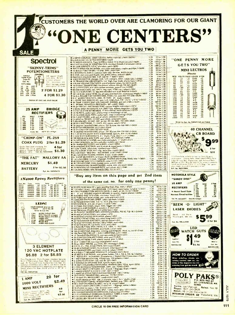
il CUSTOMERS THE WORLD OVER ARE CLAMORING FOR OUR GIANT
"ONE CENTERS" A PENNY MORE GETS YOU TWO]
Spectra "SKINNY- TRIMS"
POTENTIOMETERS SINGLE
TURN FLAT Type -63 Cat. No.
92CU3666 10 1K 25K 20 2K 5011 SO 2.56 10011 100 SK 20011 200 1011 5006 500 2011 1 Mee
3,8 square' S,nglc turn stylt Scrrw- d river adjust. YO tolerance. 0.5 Watt ratings. cermet
.ruction. PC leads.
2 FOR $1.29 4 FOR $1.30
ORDER BY CAT. NO. AND VALUE
25 AMP BRIDGE RECTIFIERS
IV 2s N 100 200 400 500 500
DALE 2 FOR 1.25 1.26 1.60 1.96 2.25 2.26 2.96 2.96 3.50 1.61 4.26 4,211 4.99 4.66 no rh...ing
orear Re 2273 & voltage
"CRIMP-ON" PL-259 COAX PLUG 2for $1.29
Qoui k, Eaa) ppi r mú ng. No 4 for Ideing. Strtpcii lation queeze. Mates to 50239. For
RG58!l' -591 C.l. Na. 82CU5688 $1.30
"THE FAT" MALLORY AA
MERCURY $1.49 BATTERY 2 for $1.50
Cat. No. 92CÚ5679
1N4000 Epoxy Rectifiers C.I. No. Typo Vous Sale It SALE! 2377 114001 SO 10 for 6 .75 20 lot 8 .76 27]6 1114002 100 10 tot .65 20 for .86 2371 1N4003 200 10 for .95 20 for .96 23110 1114004 400 IO for 1.19 20 for 1.20 2381 1114005 400 10for 1.39 20 for 1.40 2382 1114006 800 10 for 1.49 20 for 1.50 2383 1114007 1000 10 for 1.59 20 for 1.60
IXDS: YOUR CHOICE l.r $1.29 'O SALE 12 for 111.30
Order by Cat. No.
r 1700 MICRO TOOAT RED 1942 MCD YELLOW 5701132
r 11102 MICRO SINGLE PIN RED 213355 AMMO RED
i37 MICRO REO 2790 JUMBO RLD CLEAR
3 ELEMENT 120 VAC HOTPLATE $6.88 2 for $6.89
This Top Quality. Multi- Purpose Hotplate features, Builtin Thermostat. Neon "Red" AC Indicator Lamp, and 1 /8" Textured Glass Surface for even heat die tribution Generates up to 150° L'. 120 watts'. Cue for photographic applications, laboratory work, aquarium heater, plants, etc Size. 10.3 /8" x 5.3/8" x I/8 Wt. 1
lt. 2 o Cal. No. 92CU5723
1 M#11' 20 for
1000 VOLT $2.49
MINI RECTIFIERS tuin.- IN.tiiiiienlPoxv'Wed. n1fuer ,.
Pr nau.krµl ,t axial hnbhy User
Cat. No. 92C112793_
40 for
$2.50
6 -OPTO- COUPLER, 1500V 12041JOn, hobby material, u tes1142629A1 1 29 12 for 1.30
6 -2N915 UHF TO -18 TRANSISTORS(41423) 1 29 12 (0x1.30 75 -MOLEX SOCKETS, Type M1938 -4, makes 14 to 40 pin sockeIs141609) 1 29 150 for 1.30
6- CALCULATOR AC ADAPTOR JACK, standard Threads 3 terminais(42316) 1 29 12 for 1.30 50 -TUBE SOCKETS, 4,5,6,7 pin tubes, asst(038391 1 29 10010.1.30 40 CTS RESISTOR NETWORK, asst styles and values, singles and dip1,(05699) .. .1.29 80 for 1.30.
10- 11ULLEIT RECTIFIERS, 115 amp, 200V, axi.11084) 129 2010.1.30 MINI LECTROS 6- READOUTS, MAN -3, common cash, LED, the claw, RED(I3338) 1 29 12 for 1.30+ -}." B -LEDS, asst sizes and shapes, red, green,yellow, amber1O3869) 1 29 16 for 1.30
PHOTO FLASH ELECTRO. CAP, 600 MF 4 360V(o3897) 129 2 for 1.30
4 MICRO SWITCH, plunger style. N.O. contacts, SPDT, solder taba,(457851 1.29 8 for 1.30 10 TRANSISTOR /LED SOCKETS, 1/4" high, 3 -pc leads, plastic base, /05745) 1 29 20for 1.30
S -SLIDE VOLUME CONTROLS, asst of popular values, for HIF1142318) - 1 29 10 for 1.30
10- D33021 TRANSISTORS, low power, silicon, hie -60, 70- 92145627) 1 29 20 for 1.30
501 /4 WATTERS, asst value carbon resistors, some 5 %en,(t57971 1 29 100 for 1.30
60- CERAMIC CAPS, incl. NPO's, neg. coef. 84750'0 assi values(a 5901 .. 1 29 120 for 1,30
10 -TV /FM SPLICERS, for 300 ohm shielded twin lead. Bakelite.(455471 1 29 20 for 1.30
30'030 WIRE -WRAP WIRE, fits all tools and machines, continuous length,(43803) 1.29 60 for 1.30 10 -G.E. POWER TAB TRANSISTORS, 040N1,N2, some NS, TO- 2201056291 1 29 2010.1.30 3 -Sa ' BLOCK TRIM POTS, 200K .15 -TURN Pc. leads;1425351 1 29 410.1.30 1 -12VDC WAIL REED RELAY, spot, N.O. 2200 ohms, 7/8" o 5/16" o 5/16"(055151 1.29 210E 1.30
SO -TEMP. COEFFICIENT VOLTAGE REF. DIODES, asst volt, +50 i 1056471 1 29 100 for 1.30
6 -SKINNY TRIM POTS, PRECISION, SOT. yield103389) . 1 29 12 for 1.30
60 -pc- PRECUT, PRETINNED WIRE, various lengths and colors141971) 1 29 120 for 1.30
5 DUAL DIGIT READOUTS, H.P. 5082 Type, Bubble Magnifier,1457481 1.29 10 for 1.30
4 CALCULATOR KEYBOARDS, 17 keys and up, multi- IUnction,105777) 1.29 8 for 1.30 10 -5K POTS, audio taper, plastic snap -in mounling(051241 1 29 20 for 1.30 10.1 &2 MEG DUAL POTS, audio taper, snap-in mountingl45125) 1 29 20 for 1.30
50-1 AMP ZENERS, wide asst of values, untested141964) 1 29 100 (0.1.30 12- SCR'S& TRIACS, 10 AMP, asst values, untested(02087) 129 24 for 1.30
3- QUADRACS, 10 AMP, 100 ° . prime, 50- 100 -200V, TO- 220(05048) 1 29 610.1.30 20 -MINI RECTIFIERS, 1'ii AMPS, 25V, epoxy, AOia1105374) 1 29 40 for 1.30
10- 2N3704 TRANSISTORS, silicon, TO-92 case, hfe- 3001007.105625) 1 29 20 for 1.30 50 -IF TRANSFORMERS, asst sizes le 35A9/ 1 29 100 for 1.30
10 -TV CHEATER CORD JACKS1055191 129 20 for 1.30 10- 2N3705 TRANSISTORS, silicon, TO -92 cue, hie-150 100%1456261 1 29 20 for 1.30 4 -1.5V SILVER OXIDE WATCH BATTERIES ,specify; RW- 15,18(050631 129 8 for 1.30
3 -LCD WATCH READOUTS, 3'," digits, 7 seg. dim 1'4 01 "15066) 1 29 6 (0.1.30 100 RED BLOCK DISC CAPS, asst values, 507. mate,iAf(o16981 1 29 200 f0.1.30 10- INSTRUMENT KNOBS, asst styles and colon, '4" shaftI45121) 1 29 20 foe 1.30
4 -MIKE HOLDERS, for CB's and other mobile rigs1o5634) 1 29 8 foe 1.30
50-1N4000 RECTIFIERS, asst lo 800V, u 1es1(42594) 1 29 10010.1.30 20- UPRIGHT ELECTROS, asst'd values & capacitance.(03226A) 1 29 40 for 1.30
1 -UHF TUNER, solid state, standard typelo2927) 129 210.1.30 6 -ITS A SNAP, 9 VDC BAT -clip, red n black lead(42852) 1 29 12 for 1.30
8 -1400 VOLT "RED BALL" RECTIFIERS, axial 1 AMP(42590) 1 29 1610.1.30
"ONE PENNY MORE
GETS YOU TWO"
20.1N4148 SWITCHING DIODES, 4 nsec. axial(03000) 129 40foe 1.3
6 -10 AMP QUADRACS, w /Trigger diode up 600V143620) 1 29 1210.1.30 1 -8' LINE CORD, 2- cond., 18 gunge, moulded plastic plug, black, new.(05803)... 1.29 2 f0.1.30
1 29 80 10.1.30 1 29 6010.1.30 1 29 1210.1.30 1 29 30 for 1.30 1 29 1410.1.30
40- SQUARE DISC STYLE CHOKES, color coded(03203) 30- TRANSISTORS 7092 2N4400 series, u test1032911 6- TRANSISTORS TRANSFORMERS, audio, inter, etc mi0i143295) 15- PRINTED CKT TRIMMER POTS, asst values, .16433461 7- 2N3055 HOBBY NPN TRANSISTORS, TO- 3143771)
Plastic MFD. VOLTS SALE LEADS 2 FOR
25 25
15 25
.14
.17 Axial Axial
.15
.18 25 50
50 15
.24
.17 P.C.
Axial .25 .18
50 25 .19 Axial .20 50 100
100 15
.21
.23 Axial Axial .24
100 25 .25 P.C. 100 100
50 100
.35
.30 Axial Axial
.36 40
150 15 .23 Axial .21 200 15 .24 P.C. .25 220 25 .32 P.C. .33 250 250
18 25
.29
.32 Axial Axial
.30 .33
250 300
50 15
.45
.31 Axial Axial .32
300 500
25 15
.33
.33 P.C. P.C.
500 25 .38 P.C. .37 500 50 .39 Axial 1000 I5 .55 P.C.
Ord.. by Cat. No.03CUe711 and Value
*Buy any item on this page and get 2nd item of the same cat. no. for only one penny!
25 -DTL FAIRCHILD IC's, gates and flip flops, Dip, 100'Á1037091
1.24 VOLT 50 MIL. TRANSFORMER, 119V input, open frame, 1x10³/4 "1056311 5 -SPST PUSHBUTTON MOMENTARIES, rt. angle, pc ml, on -o1í 1056351
1 3" s 4" DOUBLE SIDED PC BOARD, hi- quality, copper plated,(056941 30 -RADIO AND TV KNOBS, asst styles, sizes102171 60- TUBULAR CAPACITORS, asst. volts and sizes102191 4- ROCKER SWITCHES, DPDT, solder tab Ieads,1o3302) SO -POWER RESISTORS, 3,5,7 w. axial, pop sizes1o2281
$25 SURPRISE, all kinds of parrs in a pak10294) 12 -PANEL SWITCHES, rotary, slide, toggle 0,142951 60 COILS AND CHOKES,rf, parasitic, if, e1,102971 60- TERMINAL STRIPS, oo to 4 solder lues(4334) 25- PLASTIC TRANSISTORS, untested and hobby, TO -92, TO- 18,(02604A) 50 -MICA CAPACITORS, asst valueslO3731 10 -SETS RCA PLUGS AND JACKS, phono(44021 1
60 DISC CAPACITORS, asst values long leads10437) 1 29 120 for 1.30
20- TRANSISTOR ELECTRO'S, asst up and 1x(44531 1 29 40 for 1,30
75 -HALF WATTERS, resistors, color coded, assl(04541 1 29 150 f0.1.30 35- SILVER MICAS, red backs, axial, asst(o4551 1 29 70 for 1.30
4 -PUSH BUTTON, SPST, PANEL, N.C. 125V, 'I 14145289) 1 29 8 for 1.30
100 -GERMANIUM DIODES, axial leads, u test(0642) 1 29 20010.1,30 100- STABISTORS, Regulator, sensing and computer. Axial, ex. yield143140) 1 29 200 for 1.30
100 -PRINTED CIRCUIT '4 WATT RESISTORS, assl(O10601 1 29 200 for 1.30
12- TRANSISTOR SOCKETS, asst npn and pnp types(o651) 129 24 for 1.30
50 -3 AMP SILICON RECTIFIERS, axial, asst V14865í 1 29 10010.1.30 50- POLYSTYRENE CAPS, plastic coaled, p700.(01052/ 1 29 10010.130 30 -4" CABLE TIES, non -slip while plasticlo52171 1 29 60 for 1.30
30 -pc -HEAT SHRINK, asst sizes, 507. shrinkagel45248) 129 60 for 1.30
2 -5.1V, 5%, 10W, STUD ZENER, D0 -4 ,265145287/ 1 29 4 for 1.30
10 -RCA PHONO JACKS, chasis mount, teflon base0151191 1 29 20 for 1.30
15- THERMISTORS, asst types, styles & values(02048) 1 29 30 for 1.30
4 -5 -DIGIT 7- SEGMENT READOI.IT t, in flat pak .ä1e1456161 1 29 B for 1.30
25 -METAL CAN TRANS., asst, prime, hobby, TO -1, TO -5, TO- 18,í42603A1 1.29 50 for 1.30
1-"FOTO-FET" N CHANNEL, Cryslalonics. I- Sealed Effect Transistors1011691 1 29 2 for 1.30
1- VOLTAGE REGULATOR, TO202 case, 12V 600MA(419001 1 29 2 f0.1.30 2 -3 DIGITS ON A DIP, LED, red, DL- 33(01887) 1 29 4 for 1.30
3- MM5262 2K DYNAMIC RAM, specify lype1434591 1 29 610.1.30 10 -2N711 HIGH SPEED SWITCHING TRANSISTORS, 7018, npn(a3374) 129 20 for 1.30
2 -15W HI POWER TRANSISTORS, 220V. non, 7066142797) 1 29 41or 1.30
1 -HEAVY DUTY LINE CORD, 8 ft., 2 cond. 418 gunge, black,(458031 1.29 2 for 1.30
1- MM5312 DIGITAL CLOCK CHIP, 1007.1415251 1 29 2 for 1.30
2- MM5725 4 FUNCTION CALCULATOR CHIP, 100 %(420361 1 29 4 for 1.30
25 PLASTIC TRANSISTORS. untested, TO- 92,1457311 1.29 50 for 1.30
3 -10 AMP 25V BRIDGE RECT, comb slyie(024471 1 29 6 for 1.30
1 -ALLEN BRADLEY POT. 10K. 2 -14 watts, Igoe -1, 2104' sha111417481 1 29 2 for 1.30
6- LINEAR SWITCHING TRANSISTORS, 2N2905, pnp, TOS(033751 1 29 12 for 1.30
50 -2 AMP CYLINDRICAL RECT. up to 1K, u test(o40061 - 1 29 100for 1.30
1 -HEAVY DUTY LINE CORD, 2 tond. 6 ft. 018 gunge, white,105804) 129 2 for 1.30
10- 2N22221or equiv.), TO- 18 metal case141992/ 129 20 for 1.30
10 -DATA ENTRY SWITCHES, SPST, 1 amp, norm open 125V145321) 1 29 20 for 1.30
8- TRANSISTOR RADIO EARPHONES, 8 ohms impedlo2946( 1 29 16 f0.1.30 15- FLUORESCENT OVERFLOW READOUT TUBES, w /Ieads1032881 1 29 30 for 1.30
2- ALUMINUM HEAT SINKS, for TO-220105338i 1 29 4 for 1.30
1- 2N5001 80V TRANSISTORS STUDI028001 1 29 210.1.30
40 CHANNEL ,,,44144-, CB BOARD \ i
Only \ 9 99 , 2for
!1.41 $10
Poly l'aks buy up factory chow out from 11y vain u aeon' board. have Ileals,nked 9 Watt Amp
I'h,p, HF and Mod Tramostors, and National Sem, MM series l'i.l. May he used for 10 roster , r,
',tee g month series "CH ln Ill" in 73 Map The parts aloof.. make ,t an offer you can i
Cal. N.. 92CU 5110
1 29 50 for 1.30 1.29 210.1.30 1
1 29 10 for 1,30 1.29 210.1.30 1 29 6010.1.30 1 29 12010.1.30 129 8 for 1.30
1 29 10010.1.30 1 29 210.1.30 1 29 24 f0.1.30 1 29 12010.1,30 1 29 12010.1.30 1.29 5010.1.30
1 29 10010.1.30 29 2010.1.30
MOTOROLA STYLE
"SANDY DISC " 10 AMP I "y. SALE 2FOR
20 .24
RECTIFIERS
Heavy Sand Typo
norm. Construction
.25 M 35 .36 I00 .43 44
.55 400 .ç1 1100 .1a
100 90 f 1009
92C05477 Igeiy volta..)
"BEEN -O- LIGHT" LASER DIODES Rated o 5.9 Watts Wavelength 9114 nm
Cal. No. 921:00503
s599 2 for $6
LED WATCH GUTS
$1 49 2 for
nadle: I
Cal. No.
92CUS11SC 51.50 92C115í158
HOW TO ORDER wh.n ordering. .Ivys !,1 ttslog numb.., typo no., the '
of the m.saaln non a i % Um
iï ordering from and . month 7
POLY PAKS® (:(ID's MAY HE PHONED'
P.O. BOX 942.17 SO. LYNNF7ELD, MA
Terms: Add Postage 940
Phone: 16171 1 Rated: Net 30 45 3828. Retail: 16.18 Del Carmine St. MINIMUM ORDER: S8 Wakefield, MA
CIRCLE 18 ON FREE INFORMATION CARD

CARBON FILM 1/4W -5 °/ 'QS /St0/S COS 1
270K 300X 330 3609 390K I 4301 i í70K 510K
560K 620K i 600K
i 7509 820K 91011
1.0
1 5 for .25 10 for .401100 -$160 -1000.
4.3
I 4.7
5.1 5.6
6.2
6.8 7.5
I e.: 9.1
¡ NIGH QUALITY- LOW 0 E M PRICE
mas
ü 13
15 16
nas 47 51 56 62 68
MIS
200 220 240 270 300
Das
820 910
1000 1100 1200
mas
3600 3900 4300 4700 5100
mas
15K 16K 18K 201 220
nas
62K 68K 75K 829 9Lí
18 20 22 24 27
75 82 91
100 110
330 360 390 430 470
1300 1500 1600 1800 2000
5600 6200 6800 7500 8200
2íK
301
36K
130K 110K 120K 13013 1503
30 33 36 39
43
120 130
150 160 180
510 560 620 680 750
2200 2400 2700 3000 3300
9100 101 119 13K 13K
399 438 47K 5127
56K
160K 160K 2009 220K 240K
! one ¡ value
one value 1100 per value
at Slit 1
CMOS BOARD $2.95 CONTAINS: ¡ 4553 3 digit decade counter 4511 ¡bit latch 7 msg. decoder ¡
driver for LED display 4060 oscillator v /14 stags binary
40111 04081 2
ßI. itches, reslst. CapeCitor I
I HP 2 digit LED display
i RCA to220 8A,600V1 TRIAC ea.99Ç ten -$9.50 $89 /ci
¡ BISTABLE RELAY10PTO ISOLATOR t FCD$20 6PIN DIP WILL DRIVE A TTL GATE
W1111 TEN MA LED CURRENT
3,6.1,P,us. S2.95ea169Dea ten $6
5701 yi0
200 re coils
1 Lon9 ilre llm1m.90o
pe .
Nigh peed (500 es) sealed
Ge er Si SIGNAL DIODES i High quality, marked I computer grade signal diodes. Leads trimmed i for PCB mounting....
40 for $2 1 .imee atm.-
.VOICE ACTUATED SWITCH 95tea I 5°03gP0LE e "9 1 i Iliie t'ym:ne"tar ¡
1 40` $3.-10 i I m m.
ea.- i
TRANSISTOR TBONANZA DIODE ARRAY 'Pr1oj
i;JON TM COK0ICTOR MJIUFACTORER. THESE ARE FIRST QUALITY OEVICE5 MAOE FOR A C0- i 1N914's 701 ea.
IN !%ITER FIRM. THE NPN's HAVE CUT AND FUMED i
211 PM 10 SI I uco ¡
PM w 25,each °Anrx I oM nm aa9A46tt tma I
LENGTH LEAOS.5PECIir NPN OR MP- 50 PER TY m PE 87NIM-
7. $6 for loo $50k
SUPER
SAVER
DImtAL IC's ' 2TOaT 1024 mt znt rt rw+ster TO -9' 3
I[D102s 0105 3 input Nml gate mP
catan mw z t Hum te (cams Tn w.a les
I )5411 awl pertpa
II. $ 2.25
..w MV5054 140088 to .2" red 11
diffused LED with panel mounting hdwr. PRIME PARTS.... No comet 1C
rejects 251 ea co for $10. ¡
9 ZERO CROSSING SWITCH ¡
g =Aims IPPIIII
D BÖ4ea>f 5 ten
30 3 ri Tiff fir
w 5
e 1
pu
39 488/0x6 (a) 1.3 Me098 1024 bit 15.[20 581fí reg. 8 1.5
¡ í402N was 2 input NON TTL 9.íe .1 ]4301 8 Input 0.íe .1
í492N dtvtee by I2 TT1. counter SP380 (0.836) MR BUS receiver 1.
¡0e011 quad M35 Interface IC 824 to /Pvr dual SA nip flop .2 52]0 Din caga5161e v /7100 .1
I14118 (6210) 4 6ít shift rp. .3
LÚ321 6001 36 flip flop SIG. .2 LINEAR IC's
1 111 dual 741 op -.p r1066PC 5V udla out N /hat sink
I 0411 -t (NFC6070) IN out 1,1410 (8) iW00 precision revelator T0.99
04307 -.p Ilproted 741)
uÁ167005 61 /tpa4 í04/.'6046K op/ap .31461. 331 lIP(o1U or 0099
! 4601303 Ì650m1. sterlo yllfter OIP
1 11716 r bye op /rp L7095 456 -1 Ne REGULATOR TO-3 78í2N 412 -1 341
Mel 80-3 .75
L5í112 LAMBIA 412 -3 W sockets
full TO -3 TYPE Iü@ MAT i (removed 3rá sockets fuel spectflutions guaranteed) 3.95 4P71T 3A9S
í63m9 sera crossing switch OIL .60 24VOC 650 60108 I
04703 VNF tractostor.rr s.pxy 0099 .30
i IICOS nl0c. Id
120VAC 10. ám Fat ?scald 1.201 a+etde by 4 011 scaler 39.00 lease specify $
951190 Fairchild 300465 6..4. ctc.
011(6)
1.95 mi1 required. 1 s I 010820
F.8B bit Eopt. 1507. 31.00 i Fairchild pa /iwl.ar OIL(.) .75
i SIOWL s 9n.loeioder.,lmds are6e 1/4" Single Digit i pre lamed r4 PCB .Dead specify s3f 2 /Ge 40 min. each type f2.l10 GA6P LED
12TURN'014.I'n 51(0.200K only
l9. DALE
S.50 Fóá $4
1:s YSWATT RESISTORS w 10 ea. -390, 18k, 3.9k, 6.8k, 11k
35 43k, 68k 240k - S percent tel. 1.00
2.00
OTTE 100 PR -- 1.0b BRUMFIELD
80 MR $4
0100E5 Numeric Display
1X3810 15 AMP 200 PIN stud 8 /Mw. .70 ¡ 1181581 6.4V .0062 reference diode .45
16v Motorola 156 5s IN sema .15
TRANSISTORS
zs
Oí6 1091 760 KI?13100 +m
7022K 60,PNP, í.a0
COplaanntarr 10 X46 70-220 pr. trsos- l'tors, 248101 ace GE 045468 10 /601, 75/50 13.114? Mas wir. 1
_U I 254301 N camel FET 80106 use .2s 40327 RCA NPR 300/,1 AM, 5W TO- S .35 46101 G.F. PILA 300. I NI, 66 T0-220 .30
Z I,904O3o/64030m20 tl tart. TO39164 ea 2.25 -
126 Pull ¡PO BOX 41778 m
SEND FOR FREE FLYER TODAY ¡
75 !
ONION 0.' mrsil: °sIX°tpeAtr0 eiT ;._ .a :;; a MAI« w m
ti.MpIT PT T_I L
65°each -10 for 55.95 ! u,9phVARO SEMICONDUCTOR 1
".Ìa05ÌI VMS Q .81 es. 11 for t7.51 111-tes Ti I
I- i SOCran9ent0 :inma 00.n 410.e8e 0550 00,0+ort UPS on ddooae 1110
orders i orders 8
r $10... BAC NC and VISA accepted, tes eimaul 1 w California and shipping Is added open accounts accepted ro. J I ppo t ent3t+er added..
I.a9e roae f+nn RUM SI/E MV 6NIAvEIII- tetepam (916) 331 2161 1
4811 Myrtle Avenue, T.cr.mento, CA 95441
O -
ill
C
112 CIRCLE 60 ON FREE INFORMATION CARD
ADVERTISING INDEX RADIO- ELECTRONICS does not assume any responsibility for errors that may appear in the index below.
Free Information Number Page
AMC Sales
56 A P Products, Inc 10 Aaron -Gavin Instruments 19 Active Electronics 23 Advanced Computer Products 69 Advance Electronics 37 All Electronics 30 American Antenna 66 Ampower 35 Austin Electronics 57
60
90
32
85
97
105
2, 77, 87
110
Cov. 4
108
108
82
112
90
106
92
106
14
B & K Precision Dynascan Co.
Babylon Electronics Karel Berta Bullet Electronics Burdex Security Chaney Electronics
8 Channellock C i E- Cleveland Institute of
Electronics Command Productions
26 Computer Components 16 & 29 Continental Specialties
18-21
90
98
Coy. 2 & 67
Dage Scientific 41 Davis Electronics 11 Delta Electronics 3 Digi -Key
Digital Research Corporation 54 Electra Company
Electronic Development Lab E M C- Electronic Measurements
36 Electronic Supermarket Electronic Systems
61 & 62 Fluke 38 Fordham Radio Supply
Forest Belt's Training Workshop 12 & 13 Formula International
Fuji -Svea
General Electric Godbout Electronics
98
84
92
104
96
13
92
76
100
91
69
101
81
94-95 107
34
110
86
78
70-73
33
110
96
92
75
88
102-103
98
92
27
108
100
92
106
63 47 Gould, Inc. -Instruments Div 64 Grantham College of Engineering 100 Heath 48 Hickok Electrical instruments 53 Hobby World 33 iTC- Electronic Supermarket
information Unlimited 67 Integrated Computer Systems 58 International Crystal Mfg. Co. 6 & 7 Jameco Electronics 24 Jan Crystal
Lakeside Industries 52 Leader 43 Meshna 42 Micro Mart
Millco industries 70 Natesa
National Radio Institute (NRI) Div. of McGraw -Hill
National Technical Schools 71 Nesds 44 Netronics 32 O.K. Machine & Tool 5 Ohio Scientific
8-11
28-31
98
83
15
Coy. 3
78
80
80
111
109
110
12, 24-25 93
99
20 Optoelectronics 22 PAIA 46 P T S Electronics 65 Panavise 18 Poly Paks 21 Quest 15 Quimtronix
RCA 4 Radio Shack 39 Ramsey Electronics
27 Rye industries 76 - Sabtronics 7 - Howard W. Sams & Co 23
68 Sansui 5
49 Soar 16
9 Solid State Sales 100 59 Southwest Technical Products 85 - Spacecoast Research 90
Speakerlab, Inc. 92 51 Sprague Products 22 14 Tab Books 86
40 Tek -EI Corp 106 25 Tri -Star 110 31 Ungar -Div. of Eldon Industries 79 34 Vector 84
V.I.Z. Mfg 89 28 Wersi Electronics 67 17 Zemco 17
Exercise regularl3t. American Heart Association4Th
We're Fighting For Your Life \I(
MOVING?
Don't miss a
single copy of Radio -Elec- tronlcs. Give US:
Six weeks' no- tice
Your old ad- dress and zip code
Your new ad- dress and zip code
ATTACH
LABEL
HERE
name (please print)
address
city state zip code
Mall to: Radio- Electronics SUBSCRIPTION DEPT., P.O. BOX 2520,
BOULDER, COLO. 80322

`dab'Nb'O ONV S-fl 3H1 1f1OHJf1OaH1 Sa31b'3a ObN 03a31SI931:1 009`E AEI A13AISf11OX3 03OIA1:13S aNb' alOS
011110 NOIlVW1103N1 3311A NO OE 3131113
tielaJ palsa66ns,
ozlos II'uiA13 EULlallld 11L'JI IaUi auoydaiolw ayl wan noA
ae¿ Jo asop Mon iallew ou qoaads JnoF ssaowd pue a01on ino( patas rim li anillsuas os auoydoioiw y
saualleq aoeldai Janau noA .1866u1 ay; azaanbs no( awn (Jana 96JeyO leouloala ysall e sapnoid ERB o'i ualsil noA aliyM saóJeyoe1 walsAs a6eJols oiuoiloala palualed
iS31!l311V9 ON HUM
301:1VH3 HS311A
i133d Z t!O S3HON1 t
3AIlISN3S aNnOS
syluow ¿1 Itnl e iod 'sViwwló oN suoisni=a oN am -pel leoulOSla lswe6e peslueieio ainliel leoeueyóew Isuie6e paeluelenD 6uysn o '6wddiyo 'óul)IDeJ3 lsuwe6e paalueleno sy.uow ¿l .1ol peelueien6 dpeuoglpuoou¡l
:11 33JNV11dn°J
p paunl pue pallelsw ley. ialeaC OtiN ayl wo4 sAep L wy1lM puryau pnl pue elaldwoo e wnlai Jo seoeldei p 8uo001oiw AUE wnopadlno ol paalueJen6 s: iossaoaid 4oaad3 04N 941
:1 331NV11Vn'J
AIleo!newoiny '6upseeds ai,noA eligMasiou qeo a41 lle lno s>Iuetq pue-aoion JnoA ol slsnrpe lossaooJd au' 'oiw ayl ow! tpoaiip Needs pue 'mow ino( ol filoeiip JossaOwd eyl Ilnd
JNI113ONVO 3SION
'seam leini patallnpun 'uado ui aseq Mollaw e JO{ uMop yOliMs '3104 Apo palsa6uoo 6uillno Jo¿ uoissiwsueil payolid -y6iy e Jo; dn gOliMs
iHO11MS 3NO HUM SOIIN OMI
a)liw piepuels e uenl iaMod aJOw /,pop la6 noA leyl yoaads inoA olui uie6 qp yonw os 6uidwnd sluawaaoui puooas-oioiw w li slsnlpe pue yoaads ino( saolivaw AIleogew -olle li-Jalndwoo uMO sp s,ll
i11nOa10 a3IndwOO V H11M HO33dS S3SS3OOdd
dip 6ugunow InoA Jo{ 6wdoi6 oN oipei g0 ino( ¿o apis ayl .to 'do) low 'ysep lelaw 'uwnloo 6uuaals aoepn`-' teals Aue Ol AIlueifsul sdwep lau6ew lewalw alod-no¿ paployol
id11O V 1nOH11M 31i3HMANV Sd1lO
*owe.' Aue uo auoudo.miu Aue ;uJojJad-ino o
panuesien2 sat poog os pa;uned sat anbiun os uossaaosid zpaadS

0 ñ o a
N a E ó
Y 0 t6
1 . á c '' " L o, ;. 3
4.c0
C > N :.
O `_" (.) c 2 á 0o 0 al c°nE - 1 .d á@JH g
d Q Ú oÚ t`çopv m m
C V= 0 7 C .E
LZ. 7 n e ( m
v)
`1 , Co co m U' Ñ
LL .S o >
Vl W N ro j O N W Y S Ul N m a U Eco á Q ° c
(OO
,13- v ó aEi r a . O owE 0 i
ro
O 7 E
N Ñ a a E m o Ó E N ó LL Q r 0r -0 Uf,U
EO c° ci Z F) a 0 ¢ Q 08 HNEX ó=0
1 6 i, oxbbG 0-° 1-f-U á¢xÓ=
it # #
U 2 Lo 7 a3 CT) aaai a
c <»
O N o a in
m N
N d _ -o
C 6 N
0 a m á (..) ÿ E o á
d c d E
C c m 7 ` m
Ú <4 m (7)
d 7 Q 7 ta (7#
17) .6 U 0
co >m 69
N 2...
S ¢ gaLI) § !ii ó Ñ o¢
tpp ro NmC7 O O X
U lL
(D ._
t1
ô° X O °onn HOáá x00
#
11i ln rnrn a) a)
69
.41111 .11
O N
QÓ Ux Z F #