Embed Size (px)
Citation preview

Pre-installation Checklist Varian 1200/1200L Mass Spectrometer
Use this checklist as a guide while preparing your site for the installation of the Varian 1200 or 1200L MS system. Make sure that your site meets all of the requirements detailed in these instructions before you request installation.
Complete the Checklist Refer to the appropriate topics in these instructions for more information about each item. General Requirements
The installation area is in compliance with all relevant safety regulations
The principle operator will be available during the installation and certification period
Entrance to the lab is > 100 cm (36 in.)
The workbench can support the load of the system
Sufficient bench space is available for all equipment, including optional items
Environmental Requirements
The lab temperature can be maintained between 15 and 30 ºC
The relative humidity can be maintained between 40 – 80%
The lab is free of particulate matter
The system workbench is free from vibrations
The system area is free from electromagnetic disruption and electrostatic discharge
There is a suitable exhaust system
Power Requirements The specified electrical supply and power outlets are available
Gas and Solvent Requirements
There is proper gas equipment
Nitrogen at 99.999% purity n/a
Argon at 99.999% purity n/a
Air at 99.999% purity n/a
Methane at 99.999% purity n/a
HPLC solvents available n/a
Carrier gases are available
Appropriate lab glassware is available n/a
Request Installation When you have prepared your site in accordance with this checklist, contact the Customer Service office in your region to schedule installation. Keep this checklist handy and review it with the Field Representative when arranging the installation.
Please Note: If the laboratory is not ready for installation when the Field Service Representative arrives, Varian, Inc. reserves the right to invoice for the Representative’s time.
Varian,Inc. 2700 Mitchell Drive Walnut Creek, CA 94598 U.S.A.
03-914961-00:6 1 of 24 1200/1200L MS Pre-installation Instructions
1200/1200L GC/MS and LC/MS Pre-installation Instructions
Congratulations on your purchase of the Varian 1200 Quadrupole Mass Spectrometer. The information provided in this pre-installation guide will help you prepare your installation site for your Varian 1200 GC/MS, 1200L GC/MS, 1200L LC/MS, or 1200L GC/LC/MS system. Use the general requirements and the appropriate section of these pre-installation instructions as a guide while preparing the installation site. When your site meets all the requirements detailed in these instructions, contact the Customer Service office in your region to schedule installation.
The Varian 1200L LC/MS and 1200/1200L GC/MS have been designed to operate reliably under carefully controlled environmental conditions. It is the responsibility of the customer to provide a suitable location, power source, and operating environment. Operating or maintaining a system in operational conditions outside of the power and operating environment limits described in this manual could cause failures of many types. The repair of such failures is specifically excluded from the Warranty and Service contract conditions.
CAUTION
All phases of the installation site preparation must conform to local safety, electrical, and building codes. These codes take precedence over any recommendations in these instructions, and compliance to them is the responsibility of the customer.
General Requirements.................................................. 2
Operating Environment ........................................... 2 Temperature/Humidity............................................. 2 Particulate Matter .................................................... 2 Vibration .................................................................. 2 Exhaust System ...................................................... 2
1200 GC/MS................................................................. 3 Entrance.................................................................. 3 Space and Load Requirements............................... 3 Power Requirements 1200 GC/MS......................... 4 Gas Requirements 1200 GC/MS ............................ 5
1200L GC/MS............................................................... 6 Entrance.................................................................. 6 Space and Load Requirements............................... 6 Power Requirements 1200L GC/MS....................... 7 Gas Requirements 1200L GC/MS .......................... 8
1200L LC/MS.............................................................. 10 Entrance................................................................ 10
Space and Load Requirements ............................ 10 Power Requirements 1200L LC/MS...................... 11 Gas Requirements 1200L LC/MS ......................... 12 Solvent Requirements 1200L LC/MS.................... 13
1200L GC/LC/MS ....................................................... 13 Entrance................................................................ 13 Space and Load Requirements ............................ 13 Power Requirements 1200L GC/LC/MS ............... 14 Gas Requirements 1200L GC/LC/MS................... 15 Solvent Requirements 1200L LC/MS.................... 18
Instrument Arrival ....................................................... 19 Inspection.............................................................. 19 Unpacking and Installation.................................... 20 Spare Parts ........................................................... 20 Preventive Maintenance ....................................... 20
Appendix 1. Module Specifications............................ 21 Appendix 2. Power Consumption .............................. 22 Appendix 3. NEMA Plugs and Power Outlets............ 24

General Requirements Operating Environment The customer is responsible for providing an acceptable operating environment. Attention paid to the operating environment will ensure the continued peak performance of the mass spectrometer.
Temperature/Humidity The optimal operating temperature is between 18 and 21 °C (65 and 70 °F).
NOTE: As laboratory temperature increases, system reliability decreases. All electronic components generate heat while operating. This heat must be dissipated to the surrounding air if the components are to operate reliably.
The turbomolecular pump temperature cutoff control protects the bearing to prolong the pump lifetime. A laboratory temperature above 30 °C (86 °F) may cause the pump to shut down. Operating the MS at optimal temperatures will prolong the turbo pump life.
There must be good air flow around the system. Your air conditioning system must be capable of maintaining a constant temperature (within operational limits) in the immediate vicinity of the system. The average steady-state heat load of the 1200L is 6,000 Btu, with a possible short-term heat dissipation of 15,000 Btu during startup.
Hot air vented from GC column ovens may contribute to room heating and to the resulting air conditioning load. Ducting the GC column oven air out of the lab reduces this heating effect.
The relative humidity (RH) of the operating environment must be between 40 and 80%, with no condensation. Operating the mass spectrometer at very low humidity may result in the accumulation and discharge of static electricity, shortening the life of electronic components. Operating the system at high humidity may produce condensation and result in short circuits.
Varian recommends that your laboratory be equipped with a temperature/humidity monitor. This will ensure that your laboratory is always in conformance with temperature and humidity specifications.
Particulate Matter Take necessary precautions to minimize particulates in the laboratory environment. A layer of dust on the electronic components could act as an insulating blanket and reduce heat transfer to the surrounding air.
Vibration Ensure that lab benches are free from vibrations, especially those caused by equipment in adjoining locations. Because the foreline pump vibrates during operation, install it on the floor beneath the mass spectrometer, not alongside the system on the workbench. This is especially important when using the 1200L LC, where two foreline pumps are required.
Exhaust System It is your responsibility to provide an adequate exhaust system. Most compounds introduced into the mass spectrometer will eventually be exhausted from the foreline pump, along with the small amounts of oil vapor that these pumps characteristically emit. Therefore, the pump outlets should be connected to a fume exhaust system. Consult local regulations for the proper method of exhausting the fumes from your system. LC/MS systems will require venting of the foreline
03-914961-00:6 2 of 24 1200/1200L MS Pre-installation Instructions

pumps of at least 2L/min, and venting of the API spray chamber of at least 12L/min to a separate vent line. Ensure that the exhaust system does not pull a vacuum on the API chamber.
1200 GC/MS Entrance Before arranging for delivery of the 1200 GC/MS to your facility, please make sure that all passages to the site of installation are at least 36 in. (110 cm) wide. Allow additional room for maneuvering the shipping containers around corners and/or through doors.
CAUTION
The 1200 MS, foreline pump, and gas chromatograph are heavy items that require at least two fit people for lifting and moving safely.
Space and Load Requirements The recommended layout for the 1200 MS with the gas chromatograph is illustrated in Figure 1 below. The gas chromatograph must be positioned to the left of the instrument to allow connection of the transfer line from the GC to the MS.
NOTE: This figure illustrates North American power requirements (115 Vac). See Table 1 for 230 Vac amperage requirements.
Figure 1 Recommended 1200 GC/MS System Layout
03-914961-00:6 3 of 24 1200/1200L MS Pre-installation Instructions

The 1200 GC/MS system should be installed on a clean, flat surface. The minimum bench space required for the system is 57 cm x 195 cm, for the CP-3800 GC, 1200 MS, and PC: 275 cm if the printer is on the bench as illustrated above. Ensure that the bench is capable of supporting the weight of the system: at least 150 kg plus allowances for any options.
The foreline pump plugs directly into the MS and should be positioned on the floor beneath the workbench on which the 1200 MS system sits. There is a 48 in. (1.2m) vacuum line from the rear of the MS that connects to the foreline pump. To accommodate the pump, the workbench should be no higher than 36 in. (91 cm). If you use a higher bench, be sure to place a vibrationally-isolated table or stand under the bench to elevate the pump. The table must be capable of supporting the 25 kg pump.
If your bench adjoins a wall, you will need to drill a 1.5 in. (3.8 cm) diameter hole through the rear of the bench to accommodate the vacuum hose.
The PC can be positioned either alongside the GC/MS, or on a separate table. If a separate table is chosen, it should be positioned within 10 ft (3m) of the rear of the 1200.
NOTE: See Appendix 1 for exact module specifications.
Power Requirements 1200 GC/MS The 1200 GC/MS system requires one dedicated duplex single-phase power source with earth grounds hard-wired to the main power panel ground for the gas chromatograph, and a fourplex power source for the mass spectrometer, computer, and monitor. If you have additional sample preparation devices or test equipment, we recommend a separate dedicated power source for their operation. Never plug the mass spectrometer and the chromatograph into the same power source, or you may overload the power source. Never use the free outlet on any of the power sources for equipment drawing more than 2A.
Within North America these power sources must be 20A, 100-115 Vac 60 Hz ±3 Hz. Outside North America, power sources must be 10A, 200-240 Vac, 50 Hz ±3 Hz.
Table 1 1200 GC/MS Power Requirements
Instrument Max Current Draw 110-115V (Amps)
Max Current Draw 200-240V (Amps)
CP-3800 Gas Chromatograph 20 10
1200 Mass Spectrometer 12 6
Computer 3 1.5
Monitor 3 1.5
Printer 3 1.5
NOTE: See Appendix 2 for complete current supply requirements for the standard modules.
The power cable from the GC is approximately 2 meters (80 in.) long and fitted with National Electronics Manufacturers Association (NEMA) 5-20P power plugs. The NEMA 5-20P power plug and corresponding outlet are shown in Appendix 3 Figure 5(a). NEMA 5-20P plugs are rated at 20A and 120 Vac.
The power cable from the mass spectrometer is approximately 8 ft (2.5m) long and fitted with National Electronics Manufacturers Association (NEMA) 5-15P power plugs. The NEMA 5-15P power plug and corresponding outlet are shown in Appendix 3 Figure 5(b). NEMA 5-15P plugs are rated at 15A and 120 Vac. The power cables for the computer, monitor, and printer are approximately 7 ft (2m) long. They are fitted with NEMA 5-15P plugs.
Systems shipped outside the United States and Canada are fitted with CEE 7/7 plugs which are rated at 16A and 230 Vac. The CEE 7/7 plug and outlet are shown in Appendix 3 Figure 5(c).
03-914961-00:6 4 of 24 1200/1200L MS Pre-installation Instructions

Gas Requirements 1200 GC/MS
CI Reagent Gases The CI mode for the 1200 MS typically uses methane, isobutane, or ammonia. The amount of gas consumed during CI operation is approximately 1 to 2 mL/min. The CI reagent gas should contain less than 1 ppm water. The methane, isobutane, or ammonia gas supply line connects directly to the CI gas inlet using 1/8-inch Swagelok® fittings.
Before evacuation, new gas lines typically contain significant amounts of adsorbed water vapor. The longer the gas line, the greater the pumping time required to evacuate the water from the line. To minimize pumping time, we recommend that the line be as short as possible.
Methane 5.0 Research Grade (99.999% purity) A two-stage, 0−15 psi (0−1 bar) pressure regulator that has a stainless steel diaphragm is recommended. The output pressure to the 1200 MS should be set to 3−5 psi (0.2−0.3 bar). Gas lines for methane should be made of stainless steel. All gas lines should be free of oil and preferably flame treated or solvent washed.
Isobutane 5.0 Research Grade (99.999% purity) A two-stage, 0−15 psi (0−1 bar) pressure regulator that has a stainless steel diaphragm is recommended. The output pressure to the 1200 MS should be set to 3−5 psi (0.2−0.3 bar). Gas lines for isobutane should be made of stainless steel. All gas lines should be free of oil and preferably flame treated or solvent washed.
Ammonia 5.0 Research Grade (99.999% purity) A two-stage, 0−15 psi (0−1 bar) pressure regulator that has a stainless steel diaphragm is recommended. The output pressure to the 1200 MS should be set to 3−5 psi (0.2−0.3 bar). Gas lines for ammonia should be made of stainless steel. All gas lines should be free of oil and preferably flame treated or solvent washed.
Ammonia, Anhydrous (CAS Number 7664-41-7)
Anhydrous Ammonia gas is highly toxic. Inhalation may cause irritation to eyes and throat and may cause pulmonary edema, which can result in serious injury or death. Repeated exposure to Anhydrous Ammonia may cause permanent lung damage.
• Refer to Material Safety Data Sheet (MSDS) for Anhydrous Ammonia for
exposure control/personal protection, handling/storage, accidental release, first aid, and fire fighting measure requirements.
• Anhydrous Ammonia should only be used in conjunction with an appropriate ventilation system for the instrument, the exhaust from the foreline pump, and the gas cylinder. Use appropriate safety shutoff valves for the Anhydrous Ammonia supply and interconnecting lines.
The operator is responsible for determining and implementing appropriate precautions when using Anhydrous Ammonia and for compliance with all governmental regulations. It is the operator's responsibility to understand and adhere to all safe laboratory practices concerning the use of toxic gases, including Anhydrous Ammonia.
03-914961-00:6 5 of 24 1200/1200L MS Pre-installation Instructions

CID Gas (Triple Quad only) Argon is recommended for use as a collision gas for Collision Induced Dissociation (CID) MS/MS in the triple quadrupole MS, with typical flow rates of 1 mL/min. The argon must have a purity of greater than 99% and be regulated to 5 psi.
GC Carrier Gases
Helium Helium is required as a carrier gas for the GC, with a minimum of 99.999% ultra-high purity, and less than 1.0 ppm each of water, oxygen, and total hydrocarbons. The minimum requirement is one 257 ft3 tank with an Alltech regulator #AL8111, or equivalent tank and regulator. The output gas pressure should be regulated to 80 psi.
The presence of greater than 1 ppm oxygen or water in the carrier gas supply may significantly affect the performance of the 1200 GC/MS. It may also damage such components as the capillary column, filaments, and multiplier. Varian recommends that you verify that your gas suppliers use controlled tanks to ensure that purity standards are maintained. If you purchase pure gases in contaminated tanks, you may end up with a contaminated system requiring costly and time-consuming repair.
Filter Use of a carrier gas filter is required for optimum performance and to protect your system from potential contamination. Your GC Accessory Kit includes a GC/MS Gas Clean Oxygen/Moisture filter (CP-17973) and filter base. This easy-to-remove gas filter cartridge combines three highly adsorptive materials in one filter to remove water, oxygen, and organic compounds to purify the GC/MS gas. Carrier gas filters should be installed in a location where the indicator is visible. The filter should be replaced when the indicator shows that the filter is saturated, or after one year of service. For replacement procedures, refer to the instructions enclosed with your filter.
1200L GC/MS Entrance Before arranging for delivery of the 1200L GC/MS to your facility, please make sure that all passages to the site of installation are at least 36 in. (110 cm) wide. Allow additional room for maneuvering the shipping containers around corners and/or through doors.
CAUTION
The 1200 MS, foreline pump, and gas chromatograph are heavy items that require at least two fit people for lifting and moving safely.
Space and Load Requirements The required layout for the 1200L MS with the gas chromatograph is illustrated in Figure 2. The gas chromatograph must be positioned to the left of the instrument to allow connection of the transfer line from the GC to the MS.
NOTE: This figure illustrates North American power requirements (115 Vac). See Table 2 for 230 Vac amperage requirements.
03-914961-00:6 6 of 24 1200/1200L MS Pre-installation Instructions
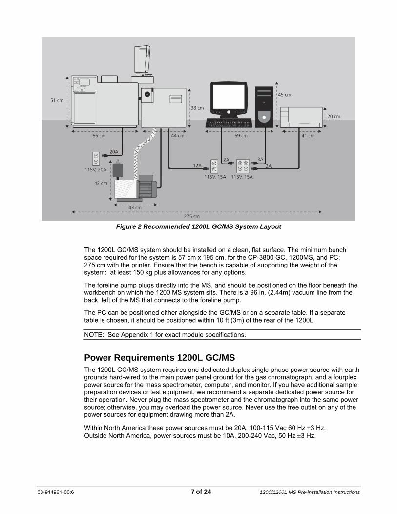
Figure 2 Recommended 1200L GC/MS System Layout
The 1200L GC/MS system should be installed on a clean, flat surface. The minimum bench space required for the system is 57 cm x 195 cm, for the CP-3800 GC, 1200MS, and PC; 275 cm with the printer. Ensure that the bench is capable of supporting the weight of the system: at least 150 kg plus allowances for any options.
The foreline pump plugs directly into the MS, and should be positioned on the floor beneath the workbench on which the 1200 MS system sits. There is a 96 in. (2.44m) vacuum line from the back, left of the MS that connects to the foreline pump.
The PC can be positioned either alongside the GC/MS or on a separate table. If a separate table is chosen, it should be positioned within 10 ft (3m) of the rear of the 1200L.
NOTE: See Appendix 1 for exact module specifications.
Power Requirements 1200L GC/MS The 1200L GC/MS system requires one dedicated duplex single-phase power source with earth grounds hard-wired to the main power panel ground for the gas chromatograph, and a fourplex power source for the mass spectrometer, computer, and monitor. If you have additional sample preparation devices or test equipment, we recommend a separate dedicated power source for their operation. Never plug the mass spectrometer and the chromatograph into the same power source; otherwise, you may overload the power source. Never use the free outlet on any of the power sources for equipment drawing more than 2A.
Within North America these power sources must be 20A, 100-115 Vac 60 Hz ±3 Hz. Outside North America, power sources must be 10A, 200-240 Vac, 50 Hz ±3 Hz.
03-914961-00:6 7 of 24 1200/1200L MS Pre-installation Instructions

Table 2 1200L GC/MS Power Requirements
Instrument Max Current Draw 100-115V (Amps)
Max Current Draw 200-240V (Amps)
CP-3800 Gas Chromatograph 20 10
1200 Mass Spectrometer 12 6
Computer 3 1.5
Monitor 3 1.5
Printer 3 1.5
NOTE: See Appendix 2 for complete current supply requirements for the standard modules.
The power cable from the GC is approximately 80 in. (2 meters) long and fitted with National Electronics Manufacturers Association (NEMA) 5-20P power plugs. The NEMA 5-20P power plug and corresponding outlet are shown in Appendix 3 Figure 5(a). NEMA 5-20P plugs are rated at 20A and 120 Vac.
The power cable from the mass spectrometer is approximately 98 in. (2.5m) long and fitted with National Electronics Manufacturers Association (NEMA) 5-15P power plugs. The NEMA 5-15P power plug and corresponding outlet are shown in Appendix 3 Figure 5(b). NEMA 5-15P plugs are rated at 15A and 120 Vac.
The power cables for the computer, monitor, and printer are approximately 80 in. (2m) long. They are fitted with NEMA 5-15P plugs.
Systems shipped outside the United States and Canada are fitted with CEE 7/7 plugs which are rated at 16A and 230 Vac. The CEE 7/7 plug and outlet are shown in Appendix 3 Figure 5(c).
Gas Requirements 1200L GC/MS
CI Reagent Gases The CI mode for the 1200L MS typically uses methane, isobutane, or ammonia. The amount of gas consumed during CI operation is approximately 1 to 2 mL/min. The CI reagent gas should contain less than 1 ppm water. The methane, isobutane, or ammonia gas supply line connects directly to the CI gas inlet using 1/8-inch Swagelok fittings.
Before evacuation, new gas lines typically contain significant amounts of adsorbed water vapor. The longer the gas line, the greater the pumping time required to evacuate the water from the line. To minimize pumping time, we recommend that the line be as short as possible.
Methane 5.0 Research Grade (99.999% purity) A two-stage, 0−15 psi (0−1 bar) pressure regulator that has a stainless steel diaphragm is recommended. The output pressure to the 1200 MS should be set to 3−5 psi (0.2−0.3 bar). Gas lines for methane should be made of stainless steel. All gas lines should be free of oil and preferably flame treated or solvent washed.
Isobutane 5.0 Research Grade (99.999% purity) A two-stage, 0−15 psi (0−1 bar) pressure regulator that has a stainless steel diaphragm is recommended. The output pressure to the 1200 MS should be set to 3−5 psi (0.2−0.3 bar). Gas lines for isobutane should be made of stainless steel. All gas lines should be free of oil and preferably flame treated or solvent washed.
03-914961-00:6 8 of 24 1200/1200L MS Pre-installation Instructions

Ammonia 5.0 Research Grade (99.999% purity) A two-stage, 0−15 psi (0−1 bar) pressure regulator that has a stainless steel diaphragm is recommended. The output pressure to the 1200 MS should be set to 3−5 psi (0.2−0.3 bar). Gas lines for ammonia should be made of stainless steel. All gas lines should be free of oil and preferably flame treated or solvent washed.
Ammonia, Anhydrous (CAS Number 7664-41-7)
Anhydrous Ammonia gas is highly toxic. Inhalation may cause irritation to eyes and throat and may cause pulmonary edema, which can result in serious injury or death. Repeated exposure to Anhydrous Ammonia may cause permanent lung damage.
• Refer to Material Safety Data Sheet (MSDS) for Anhydrous Ammonia for
exposure control/personal protection, handling/storage, accidental release, first aid, and fire fighting measure requirements.
• Anhydrous Ammonia should only be used in conjunction with an appropriate ventilation system for the instrument, the exhaust from the foreline pump, and the gas cylinder. Use appropriate safety shutoff valves for the Anhydrous Ammonia supply and interconnecting lines.
The operator is responsible for determining and implementing appropriate precautions when using Anhydrous Ammonia and for compliance with all governmental regulations. It is the operator's responsibility to understand and adhere to all safe laboratory practices concerning the use of toxic gases, including Anhydrous Ammonia.
CID Gas (Triple Quad only) Argon is recommended for use as a collision gas for Collision Induced Dissociation (CID) MS/MS in the triple quadrupole MS, with typical flow rates of 1 mL/min. The argon must have a purity of greater than 99%, and be regulated to 5 psi.
GC Carrier Gases
Helium Helium is required as a carrier gas for the GC, with a minimum of 99.999% ultra-high purity, and less than 1.0 ppm each of water, oxygen, and total hydrocarbons. The minimum requirement is one 257 ft3 tank with an Alltech regulator #AL8111, or equivalent tank and regulator.
The presence of greater than 1 ppm oxygen or water in the carrier gas supply may significantly affect the performance of the 1200 GC/MS. It may also damage such components as the capillary column, filaments, and multiplier. Varian recommends that you verify that your gas suppliers use controlled tanks to ensure that purity standards are maintained. If you purchase pure gases in contaminated tanks, you may end up with a contaminated system requiring costly and time-consuming repair.
03-914961-00:6 9 of 24 1200/1200L MS Pre-installation Instructions

Filter Use of a carrier gas filter is required for optimum performance and to protect your system from potential contamination. Your GC Accessory Kit includes a GC/MS Gas Clean Oxygen/Moisture filter (CP-17973) and filter base. This easy-to-remove gas filter cartridge combines three highly adsorptive materials in one filter to remove water, oxygen, and organic compounds to purify the GC/MS gas. Carrier gas filters should be installed in a location where the indicator is visible. The filter should be replaced when the indicator shows that the filter is saturated, or after one year of service. For replacement procedures, refer to the instructions enclosed with your filter.
1200L LC/MS Entrance Before arranging for delivery of the 1200L LC/MS to your facility, please make sure that all passages to the site of installation are at least 36 in. (91.5 cm) wide. Allow additional room for maneuvering the shipping containers around corners and/or through doors.
CAUTION
The 1200L MS, foreline pumps, and Liquid Chromatograph are heavy items that require at least two fit people for lifting and moving safely.
Space and Load Requirements The required layout for the 1200L MS with the LC is illustrated in Figure 3. The LC should be positioned to the left of the instrument to minimize the delay volume between the LC and the MS.
NOTE: This figure illustrates North American power requirements (115 Vac). See Table 3 for 230 Vac amperage requirements.
03-914961-00:6 10 of 24 1200/1200L MS Pre-installation Instructions

Figure 3 Recommended 1200L LC/MS System Layout
The 1200L LC/MS system should be installed on a clean, flat surface. The minimum bench space required for the system is 57 cm x 210 cm for the LC, 1200, and PC, 275 cm with the printer. Ensure that the bench is capable of supporting the weight of the system: at least 200 kg plus allowances for any options.
The 1200L MS uses two foreline pumps that should be positioned on the floor beneath the workbench on which the 1200L MS system sits. There is a 96 in. (2.44m) vacuum line from the back, left of the MS that connects to the foreline pumps, and a pump controller that must be positioned within 80 in. (2m) of the MS.
Power Requirements 1200L LC/MS The 1200L LC/MS system requires two dedicated fourplex single-phase power sources with earth grounds hard-wired to the main power panel ground, and one 230V 20A power source. One of these fourplex power sources is for the mass spectrometer, computer, and monitor; the other fourplex power source is for the liquid chromatograph, and the 230V 20A source is for the foreline pumps. If you have additional sample preparation devices or test equipment, we recommend a separate dedicated power source for their operation. Never plug the mass spectrometer and the chromatograph into the same power source, or you may overload the fourplex power source. Never use the free outlet on any of the power sources for equipment drawing more than 2A.
Within North America these power sources must be 20A, 120 Vac, 60 Hz ±3 Hz and 20A, 230 Vac, 60 Hz ±3 Hz for the two foreline pumps.
Outside North America power sources must be 10A, 230 Vac, 50 Hz ±3 Hz and 20A, 230V 50 Hz ±3 Hz for the two foreline pumps.
03-914961-00:6 11 of 24 1200/1200L MS Pre-installation Instructions

Table 3 1200L LC/MS Power Requirements
Instrument Max Current Draw 100-115V (Amps)
Max Current Draw 200-240V (Amps)
ProStar 210/215 Pumps 2.25 each 1.125 each
ProStar 430 AutoSampler 2 1
1200L Mass Spectrometer 12 6
602 Foreline pumps Not recommended 20
Computer 3 1.5
Monitor 3 1.5
Printer 3 1.5
NOTE: See Appendix 2 for complete current supply requirements for the standard modules.
The power cable from the mass spectrometer is approximately 98 in. (2.5m) long and fitted with National Electronics Manufacturers Association (NEMA) 5-15P power plugs. The NEMA 5-15P power plug and corresponding outlet are shown in Appendix 3 Figure 5(b). NEMA 5-15P plugs are rated at 15A and 120 Vac.
The power cable from the foreline pump box for the LC/MS is approximately 78 in. (2m) long and fitted with a National Electronics Manufacturers Association (NEMA) 6-20 power plug. The NEMA 6-20 plugs are rated at 20A and 220 Vac. The NEMA 6-20 plug and corresponding outlet are shown in Appendix 3 Figure 5(d).
The power cables for the computer, monitor, and printer are approximately 78 in. (2m) long. They are fitted with NEMA 5-15P plugs.
Systems shipped outside the United States and Canada are fitted with CEE 7/7 plugs which are rated at 16A and 230 Vac. The CEE 7/7 plug and outlet are shown in Appendix 3 Figure 5(c).
Gas Requirements 1200L LC/MS
Nitrogen A Nitrogen gas supply capable of providing up to 12L/min of gas regulated at 80 psi is required as a nebulizing and drying gas. The nitrogen must have a purity greater than 99%, with less than 0.1 ppm hydrocarbons, and less than 1% oxygen. The nitrogen should be dry, with a −40 degree dew point. Varian recommends the use of a nitrogen generator, or liquid nitrogen blow-off to supply the gas. All nitrogen generators require regular maintenance to continue to perform to specification. The nitrogen generator manufacturer should be consulted as to preventative maintenance requirements of the instrument, and the schedule must be followed. Any problems with the MS that are found to be caused by poor gas quality are not covered under Warranty. It is the customer’s responsibility to conform to all regulations regarding the installation and operation of the gas system.
Air A compressed air gas supply that is capable of providing up to 2L/min of gas regulated to 80 psi is required for negative ESI as a nebulizing gas. It is the customer's responsibility to conform to all regulations regarding the installation and operation of the gas system. The air should be clean and dry, with less than 0.1 ppm total hydrocarbons, including methane, and a −40 degree dew point.
03-914961-00:6 12 of 24 1200/1200L MS Pre-installation Instructions

CID Gas (Triple Quad only) Argon is recommended for use as a Collision Induced Dissociation gas for MS/MS in the triple quadrupole MS, with a typical flow rate of 1 mL/min. The argon must have a purity of greater than 99% and be regulated to 1−3 psi (0.1−0.2 bar).
Solvent Requirements 1200L LC/MS Installation by a Varian Field Service Representative will normally include a basic test of the system’s functionality.
Mobile phase solvents required for installation are methanol and de-ionized water. All solvents should be pure HPLC-grade, and degassing apparatus should be available, if required.
You will need to provide the following glassware for diluting the standards used to mass calibrate the instrument:
• two 50 mL volumetric flasks • two 1.0 mL pipettes
In addition to the above, interconnect tubing will be required to complete installation of your system. Most of this tubing is included in the accessory kits of specific LC instrument modules. Additional tubing (PEEK® or Stainless Steel) may be required for installation of special valving or installation of modules to existing HPLC systems.
For most analytical HPLC systems (flow rates up to 10 mL/min), 1/16" tubing with an internal diameter (ID) of 0.005” can be used throughout. However, 0.005" ID or smaller should always be used downstream of the sample injector or autosampler to prevent peak broadening. In addition, tubing lengths should always be kept to a minimum.
Semiprep and Preparative systems have other requirements/limitations with regard to interconnect tubing. Typically, a system using flow rates up to 200 mL/min will require 1/16" OD tubing with an internal diameter as high as 0.040". On these systems, tubing ID used after the injector/autosampler should be ~0.010" smaller than tubing used in the rest of the system. On Prep systems, 1/8" tubing (0.062" or 0.080" ID) is typically used throughout. Always consult the instrument module Operator’s Manual for specific recommendations.
1200L GC/LC/MS Entrance Before arranging for delivery of the 1200L GC/LC/MS to your facility, please make sure that all passages to the site of installation are at least 36 in. (91.5 cm) wide. Allow additional room for maneuvering the shipping containers around corners and/or through doors.
CAUTION
The 1200L MS, foreline pumps, GC, and LC are heavy items that require at least two fit people for lifting and moving safely.
Space and Load Requirements The required layout for the 1200L MS with the HPLC is illustrated in Figure 4. The gas chromatograph must be positioned to the left of the instrument to allow connection of the transfer line from the GC to the MS. The 1200L MS uses two foreline pumps that should be positioned on the floor beneath the workbench on which the 1200L MS system sits. There is a 96 in. (2.44m) vacuum line from the back, left of the MS that connects to the foreline pumps, and a pump controller that must be positioned within 80 in. (2m) of the MS.
03-914961-00:6 13 of 24 1200/1200L MS Pre-installation Instructions

NOTE: This figure illustrates North American power requirements (115 Vac). See Table 4 for 230 Vac amperage requirements.
Figure 4 Recommended 1200L GC/LC/MS System Layout
The 1200L GC/LC/MS system should be installed on a clean, flat surface. The minimum bench space required for the system is 57 cm x 250 cm for the HPLC, 1200, and PC, 325 cm with the printer. Ensure that the bench is capable of supporting the weight of the system: at least 250 kg plus allowances for any options.
Power Requirements 1200L GC/LC/MS The 1200L GC/LC/MS system requires a dedicated duplex power source for the GC, two dedicated fourplex single-phase power sources with earth grounds hard-wired to the main power panel ground for the HPLC, MS, and computer, and one 230V 20A power source for the foreline pumps. If you have additional sample preparation devices or test equipment, we recommend a separate dedicated power source for their operation. Never plug the mass spectrometer and the chromatograph into the same power source, or you may overload the fourplex power source. Never use the free outlet on any of the power sources for equipment drawing more than 2A
Within North America these power sources must be 20A, 120 Vac, 60 Hz ±3 Hz and 20A, 230 Vac, 60 Hz ±3 Hz for the two foreline pumps.
Outside North America power sources must be 10A, 230 Vac, 50 Hz ±3 Hz and 20A, 230V 50 Hz ±3 Hz for the two foreline pumps.
03-914961-00:6 14 of 24 1200/1200L MS Pre-installation Instructions

Table 4 1200L GC/LC/MS Power Requirements
Instrument Max Current Draw 100-115V (Amps)
Max Current Draw 200-240V (Amps)
CP-3800 Gas Chromatograph 20 10
ProStar 210/215 Pumps 2.25 each 1.125 each
ProStar 430 AutoSampler 2 1
1200L Mass Spectrometer 12 6
602 Foreline pumps Not recommended 20
Computer 3 1.5
Monitor 3 1.5
Printer 3 1.5
NOTE: See Appendix 2 for complete current supply requirements for the standard modules.
The power cable from the mass spectrometer is approximately 98 in. (2.5m) long and fitted with National Electronics Manufacturers Association (NEMA) 5-15P power plugs. The NEMA 5-15P power plug and corresponding outlet are shown in Appendix 3 Figure 5(b). NEMA 5-15P plugs are rated at 15A and 120 Vac.
The power cable from the foreline pump box for the LC/MS is approximately 78 in. (2m) long fitted with a National Electronics Manufacturers Association (NEMA) 6-20P power plug. The NEMA 6-20P plugs are rated at 20A and 220 Vac. The NEMA 6-20P plug and corresponding outlet are shown in Appendix 3 Figure 5(d).
The power cable from the GC is approximately 78 in. (2m) long and fitted with National Electronics Manufacturers Association (NEMA) 5-20P power plugs. The NEMA 5-20P power plug and corresponding outlet are shown in Appendix 3 Figure 5(a). NEMA 5-20P plugs are rated at 20A and 120 Vac.
The power cables for the computer, monitor, and printer are approximately 78 in. (2m) long. They are fitted with NEMA 5-15P plugs.
Systems shipped outside the United States and Canada are fitted with CEE 7/7 plugs which are rated at 16A and 230 Vac. The CEE 7/7 plug and outlet are shown in Appendix 3 Figure 5(c).
Gas Requirements 1200L GC/LC/MS
Nitrogen A Nitrogen gas supply capable of providing up to 12L/min of gas regulated at 80 psi is required as a nebulizing and drying gas. The nitrogen must have a purity greater than 99%, with less than 0.1 ppm hydrocarbons, and less than 1% oxygen. The nitrogen should be dry, with a −40 degree dew point. Varian recommends the use of a nitrogen generator, or liquid nitrogen blow-off to supply the gas. All nitrogen generators require regular maintenance to continue to perform to specification. The nitrogen generator manufacturer should be consulted as to preventative maintenance requirements of the instrument, and the schedule must be followed. Any problems with the MS that are found to be caused by poor gas quality are not covered under Warranty. It is the customer’s responsibility to conform to all regulations regarding the installation and operation of the gas system.
03-914961-00:6 15 of 24 1200/1200L MS Pre-installation Instructions
Air A compressed air gas supply that is capable of providing up to 2L/min regulated to 80 psi is required for negative ESI as a nebulizing gas. It is the customer's responsibility to conform to all regulations regarding the installation and operation of the gas system. The air should be clean and dry, with less than 0.1 ppm total hydrocarbons, including methane, and a –40 degree dew point.
CI Reagent Gases The CI mode for the 1200L MS typically uses methane, isobutane, or ammonia. The amount of gas consumed during CI operation is approximately 1 to 2 mL/min. The CI reagent gas should contain less than 1 ppm water. The methane, isobutane, or ammonia gas supply line connects directly to the CI gas inlet using 1/8” Swagelok fittings.
Before evacuation, new gas lines typically contain significant amounts of adsorbed water vapor. The longer the gas line, the greater the pumping time required to evacuate the water from the line. To minimize pumping time, we recommend that the line be as short as possible.
Methane 5.0 Research Grade (99.999% purity) A two-stage, 0−15 psi (0−1 bar) pressure regulator that has a stainless steel diaphragm is recommended. The output pressure to the 1200 MS should be set to 3−5 psi (0.2−0.3 bar). Gas lines for methane should be made of stainless steel. All gas lines should be free of oil and preferably flame treated or solvent washed.
Isobutane 5.0 Research Grade (99.999% purity) A two-stage, 0−15 psi (0−1 bar) pressure regulator that has a stainless steel diaphragm is recommended. The output pressure to the 1200 MS should be set to 3−5 psi (0.2−0.3 bar). Gas lines for isobutane should be made of stainless steel. All gas lines should be free of oil and preferably flame treated or solvent washed.
Ammonia 5.0 Research Grade (99.999% purity) A two-stage, 0−15 psi (0−1 bar) pressure regulator that has a stainless steel diaphragm is recommended. The output pressure to the 1200 MS should be set to 3−5 psi (0.2−0.3 bar). Gas lines for ammonia should be made of stainless steel. All gas lines should be free of oil and preferably flame treated or solvent washed.
03-914961-00:6 16 of 24 1200/1200L MS Pre-installation Instructions

Ammonia, Anhydrous (CAS Number 7664-41-7)
Anhydrous Ammonia gas is highly toxic. Inhalation may cause irritation to eyes and throat and may cause pulmonary edema, which can result in serious injury or death. Repeated exposure to Anhydrous Ammonia may cause permanent lung damage.
• Refer to Material Safety Data Sheet (MSDS) for Anhydrous Ammonia for
exposure control/personal protection, handling/storage, accidental release, first aid, and fire fighting measure requirements.
• Anhydrous Ammonia should only be used in conjunction with an appropriate ventilation system for the instrument, the exhaust from the foreline pump, and the gas cylinder. Use appropriate safety shutoff valves for the Anhydrous Ammonia supply and interconnecting lines.
The operator is responsible for determining and implementing appropriate precautions when using Anhydrous Ammonia and for compliance with all governmental regulations. It is the operator's responsibility to understand and adhere to all safe laboratory practices concerning the use of toxic gases, including Anhydrous Ammonia.
CID Gas (Triple Quad only) Argon is recommended for use as a Collision Induced Dissociation gas for MS/MS in the triple quadrupole MS, with a typical flow rate of 1 mL/min. The argon must have a purity of greater than 99%, and be regulated to 1−3 psi (0.1−0.2 bar).
GC Carrier Gas
Helium Helium is required as a carrier gas for the GC, with a minimum 99.999% ultra-high purity, and less than 1.0 ppm each of water, oxygen, and total hydrocarbons. The minimum requirement is one 257 ft3 tank with an Alltech regulator #AL8111, or equivalent tank and regulator.
The presence of greater than 1 ppm oxygen or water in the carrier gas supply may significantly affect the performance of the 1200 GC/MS. It may also damage such components as the capillary column, filaments, and multiplier. Varian recommends that you verify that your gas suppliers use controlled tanks to ensure that purity standards are maintained. If you purchase pure gases in contaminated tanks, you may end up with a contaminated system requiring costly and time-consuming repair.
Filter Use of a carrier gas filter is required for optimum performance and to protect your system from potential contamination. Your GC Accessory Kit includes a GC/MS Gas Clean Oxygen/Moisture filter (part number CP-17973) and filter base. This easy-to-remove gas filter cartridge combines three highly adsorptive materials in one filter to remove water, oxygen, and organic compounds to purify the GC/MS gas. Carrier gas filters should be installed in a location where the indicator is visible. The filter should be replaced when the indicator shows that the filter is saturated, or after one year of service. For replacement procedures, refer to the instructions enclosed with your filter.
03-914961-00:6 17 of 24 1200/1200L MS Pre-installation Instructions

Solvent Requirements 1200L LC/MS Installation by a Varian Field Service Representative will normally include a basic test of the systems functionality.
Mobile phase solvents required for installation are methanol and de-ionized water. All solvents should be pure HPLC-grade, and degassing apparatus should be available, if required.
You will need to provide the following glassware for diluting the standards used to tune the instrument:
• two 50 mL volumetric flasks • two 1.0 mL pipettes
In addition to the above, interconnect tubing will be required to complete installation of your system. Most of this tubing is included in the accessory kits of specific LC instrument modules. Additional tubing (PEEK® or stainless steel) may be required for installation of special valving, or installation of modules to existing HPLC systems.
For most analytical HPLC systems (flow rates up to 10 mL/min), 1/16" tubing with an internal diameter (ID) of 0.005" can be used throughout. However, 0.005" ID or smaller should always be used downstream of the sample injector or autosampler to prevent peak broadening. In addition, tubing lengths should always be kept to a minimum.
Semiprep and Preparative systems have other requirements/limitations with regard to interconnect tubing. Typically, a system using flow rates up to 200 mL/min will require 1/16" OD tubing with an internal diameter as high as 0.040". On these systems, tubing ID used after the injector/autosampler should be ~0.010" smaller than tubing used in the rest of the system. On Prep systems, 1/8" tubing (0.062" or 0.080" ID) is typically used throughout. Always consult the instrument module Operation Manual for specific recommendations.
03-914961-00:6 18 of 24 1200/1200L MS Pre-installation Instructions

Instrument Arrival Inspection When the 1200L LC/MS or 1200/1200L GC/MS arrives, carefully inspect the exterior of the shipping cartons for evidence of any damage that might have occurred during shipment. Inspect the cartons for the following: • Water stains • Cuts, punctures, or deep indentations • Crushed corners or excessively abraded edges • Beads in the Tip (N) Tell device.
Two Tip (N) Tell indicators and labels are affixed to the exterior of the shipping boxes. Read and follow the instructions on the label. If there are beads in the arrow portion of the indicator, the box may have been tipped and instrument damage may have occurred during shipping.
If one or more of the above conditions are evident on any of the shipping cartons, report the conditions to the carrier at time of receipt. Note the damage on all copies of the shipping documents, and briefly describe in writing the damage. The driver should sign next to your comments to signify agreement with the observations. Contact the appropriate Varian office to report the damage.
If no external damage is apparent, receiving documents should be signed “Received but not inspected” to indicate that the boxes have not been opened.
Systems are shipped either FOB Varian or FOB Destination. The manner of shipment determines who has responsibility for filing a claim against the carrier if the system is damaged in transit. Most systems are shipped FOB Varian, and any damages incurred in shipment are the responsibility of the purchaser and the carrier. Contact the Varian office for assistance with claims filing and billing for repairs if necessary. If the system is shipped FOB Destination, contact the Varian office, who will file a claim against the carrier.
Varian will not accept liability for damage if obviously damaged materials are received without noting damage on the receiving documents.
Move the shipping containers to a warm, dry, secure area near the place of installation. Do not open any of the boxes until the Varian field Service Representative arrives for installation.
03-914961-00:6 19 of 24 1200/1200L MS Pre-installation Instructions

Unpacking and Installation Before coming on site for installation, a Varian Field Service Representative will contact you to go through the “Pre-installation Checklist” at the front of this document to ensure that all of the site requirements have been met. The Varian Field Service Representative will unpack and install the 1200L LC/MS or 1200/1200L GC/MS and will demonstrate the fundamental operation and maintenance of the MS. It is therefore important to have the system operator available during the installation. The Varian Field Service Representative will only use the Varian supplied computer to perform the testing of system specifications. Varian does not guarantee the workstation software to function on any other computer hardware or operating system.
The Varian Field Service Representative will also demonstrate that your system meets the performance specifications written into your sales contract. Do not plan to analyze samples with the system until after the installation has been completed and you have accepted the conditions of delivery.
Spare Parts The 1200/1200L Hardware Operation Manual provides a list of spare parts for routine operation.
Preventive Maintenance The customer is responsible for performing routine and preventive maintenance of the chromatograph, mass spectrometer, and data system. Any nitrogen generator used will require preventative maintenance to ensure the nitrogen supply is clean and dry. Any instrument problems that are a result of a contaminated gas supply are billable and not included in the Warranty.
It is essential to perform regular preventive maintenance to increase the life of the system, maximize system uptime, and optimize system performance. Refer to the 1200/1200L Hardware Operation Manual for details. Your Varian Field Service Representative will describe and demonstrate these procedures at the time of installation.
Trademark Acknowledgment Microsoft® and Windows® are registered trademarks of Microsoft Corporation. Swagelok is a registered trademark of Swagelok Company, Solon, Ohio. Other brand and product names are trademarks or registered trademarks of their respective holders.
03-914961-00:6 20 of 24 1200/1200L MS Pre-installation Instructions

Appendix 1. Module Specifications The following table identifies the space and weight requirements for Varian MS, LC, and GC components. Varian MS systems are intended to sit on a workbench that is wide enough and deep enough to accommodate these components, and sturdy enough to support their combined weight. Please note that some of the LC modules are stackable and that the GC/MS systems will require enough extra bench space to allow the GC to be moved away from the MS for servicing and replacement of the transfer line.
Table 5 Dimensions and Weights of the 1200/1200L System Components
Height Width Depth Weight
Instrument in. cm in. cm in. cm lb. kg
1200 MS* 21 53 45 114 22.5 57.15 141* 62.5*
1200L MS* 21 53 45 114 24.8 63 227* 103*
ProStar 210, 220, 230, 240 11.5 29.2 11.5 29.2 20 51 53 24
PrepStar 218, 530 7.75 19.7 11.5 29.2 18.25 46.4 48 22
PrepStar SD-1 10.5 27 16 41 22 56 75 34
PrepStar SD-2 7.75 19.7 11.5 29.2 20.25 57.5 60 27
ProStar 500 Column Valve Module 20 50.8 5.4 13.7 15 38.1 30 13.6
ProStar 310 UV-Vis Detector 11 27.9 11.5 29.2 19.75 50.2 45 20.4
ProStar 320 UV-Vis Detector 5.8 14.7 11.5 29.2 18.25 46.4 22 10
ProStar 325 Photodiode Array Detector 8.3 21.2 11.7 29.6 18.7 47.5 34 15.5
ProStar 330 Photodiode Array Detector 9.3 23.5 10.2 26 20 50 35 16
ProStar 335 Photodiode Array Detector 8.3 21.2 11.7 29.6 18.7 47.5 34 15.5
ProStar 340 UV-Vis Detector 6.3 16 9.8 25 13.3 33.5 20 9
ProStar 345 UV-Vis Detector 5.9 15 14.6 37 18.5 47 40 18
ProStar 363 Fluorescence Detector 12.0 30.5 11.5 29.2 18.5 47 42 19
ProStar 400 AutoSampler 11.1 28.2 11.8 30 17.3 44 41 19
ProStar 410 AutoSampler 13.4 34 11.8 30 19.7 50 46 21
ProStar 420 AutoSampler 17.3 44 11 28 21.3 54 66 29
ProStar 430 AutoSampler 17.3 44 11 28 15.7 40 58 26
ProStar 701 Fraction Collector 15 38 11.4 29 24 61 23 10.4
ProStar 704 Fraction Collector 13 33 10.9 28 12.3 31 10.4 4.7
CP-3800 GC 20 51 26 66 22 56 95 43
Combi PAL AutoSampler 26.5 64.8 33.8 82.8 13.7 33.5 27.7 10
CP-8400 AutoSampler/CP-8410 AutoInjector 16 41 9 23 18 46 20 9
CP-8200 AutoSampler 20 51 6 16 16 41 24 11
Tekmar 3100 Purge and Trap Autosampler 19 48 9 23 18 46 37 17
Archon Purge and Trap AutoSampler 17 43 22 55 21 53 80 36
Tekmar ALS-2016 27 69 15 38 15 38 35 16
Genesis Headspace AutoSampler 22 56 28 71 18 46 110 50
Varian MS Workstation (computer with monitor, approximate values)
20 51 17 43 21 53 35 16
* Weight includes foreline pumps.
03-914961-00:6 21 of 24 1200/1200L MS Pre-installation Instructions

Table 6 Spatial Setup Recommendations for 1200L LC/MS and GC/MS
Recommendations Purpose Recommended Distance
Allow adequate space to the side of the LC.
Solvent bottle placement for HPLC pumps. See Figure 3.
≥ 24 in. (61 cm)
Allow adequate space to the side of the GC/MS.
Permit access to the transfer line. See Figure 1.
~ 24 in. (61 cm)
Allow adequate space behind the system.
Provide clear space for air circulation, gas lines, and electrical connections.
6 to 12 in. (15 to 30 cm)
Allow vertical clearance above the instrument.
Dissipate heat and allow for routine maintenance.
≥ 30 in. (76 cm)
Allow additional bench space beside the Workstation keyboard.
Enable mouse operation. 8 in. x 8 in. (20 cm x 20 cm)
Appendix 2. Power Consumption Table 7 Specifications for maximum power draws for UPS systems (uninterruptible power supply)
MS Configuration Maximum Power Draw
1200L LCMS without pumps 1200 VA
1200L GCMS with DS102 pump 1200 VA
1200 with DS102 pump 1200 VA
1200L LCMS Pumps (2 DS602 pumps) 3072 VA, 5280 VA surge < 30 sec, 10900 VA surge < 1 sec
03-914961-00:6 22 of 24 1200/1200L MS Pre-installation Instructions

Table 8 Maximum Power Draws for Varian Modules
Component 100-115 Vac (Amperes)
200-240 Vac (Amperes)
Mass Spectrometer 12 6
LC/MS Foreline pumps (2 ea. @ 220V) N/A 20
ProStar 210/215 SDM 2.25 1.125
ProStar 220, 230, 240 SDM 2.25 1.125
PrepStar SD-1 SDM 3.0 1.5
PrepStar SD-2 (220V only) SDM 3.3 1.65
PrepStar 218 SDM 4.6 2.3
ProStar 310 UV-Vis 2.0 1
ProStar 320 UV-Vis 1.3 0.75
ProStar 325 Photodiode Array 1.1 0.55
ProStar 330 Photodiode Array 1.7 0.9
ProStar 335 Photodiode Array 1.1 0.55
ProStar 340 UV-Vis 0.9 0.45
ProStar 345 UV-Vis 1.7 0.9
ProStar 363 Fluorescence 3.0 1.5
ProStar 400 AutoSampler 1.7 0.85
ProStar 410 AutoSampler 1.25 0.625
ProStar 420 AutoSampler 1.7 0.9
ProStar 430 AutoSampler 2.1 1.05
ProStar 701 Fraction Collector 0.6 0.3
ProStar 704 Fraction Collector 0.2 0.1
CP-3800 Gas Chromatograph 20 10
CP-8400 AutoSampler 0.5 0.25
Combi PAL 0.7 1.5
Computer 3 1.5
Monitor 3 1.5
Laser Printer 3-4 1.5-2
Never plug the mass spectrometer and the chromatograph into the same power source; otherwise, you may overload the power source. Never use the free outlet on any of the power sources for equipment drawing more than 2A.
The quality of the power supplied to your LC/MS or GC/MS is very important. The power must be 100-130 Vac, 60 Hz ±3 Hz (200-260 Vac, 50 Hz ±3 Hz outside North America), and 200-240 Vac, 60 Hz ±3 Hz for LC/MS (50 Hz ±3 Hz for outside North America), and it must be stable, i.e., it must be free of fluctuations due to slow changes in the average voltage or to changes resulting from surges, sags, or transients.
• Slow average changes are gradual, long-term changes in the average root mean square (RMS) voltage level, with typical durations greater than 2 seconds.
• Sags and surges are sudden changes in average RMS voltage level, with typical durations between 50 µsec and 2 seconds.
• Transients (or impulses) are brief voltage excursions of up to several thousand volts with durations of less than 50 µsec.
03-914961-00:6 23 of 24 1200/1200L MS Pre-installation Instructions

Constant high line voltage or surges in voltage may produce overheating and component failures. Constant low line voltage or sags in voltage may cause the system to function erratically, or even to cease functioning. Transients, even of a few microseconds duration, may cause electronic devices to fail catastrophically or degrade sufficiently to significantly shorten device lifetime. It is important to establish the quality of the line power in your laboratory prior to installation of the 1200L LC/MS and/or GC/MS.
Occasionally, line power sources may be of unacceptable quality. Such power sources may adversely affect the operation of the 1200L LC/MS and/or GC/MS. In this case, contact a local specialist in power conditioning services.
Appendix 3. NEMA Plugs and Power Outlets
Figure 5 NEMA 5-20P, NEMA 5-15P, CEE 7/7 and NEMA 6-20 Power Plugs and Outlets
03-914961-00:6 24 of 24 1200/1200L MS Pre-installation Instructions