Embed Size (px)
Citation preview
1
Using the Sonnet Electromagnetic Analysis to Discover the Secrets of Small Antenna Design for RFID and
Bluetooth Wireless Communications
ソネットソフトウェアインク日本支店[email protected]
www.sonnetusa.com/jp/
2002/11/21ソネットソフトウェアインク出展企業セミナ
James C. RautioSonnet Software, [email protected]
Over the last several years, RFID and Bluetooth have become major markets. With a large number of vendors, success will be determined by achieving a short time-to-market for the most creative ideas. In order to realize a short time-to-market, fast and accurate electromagnetic analysis is an absolute requirement. This presentation demonstrates using Sonnet to evaluate a 13.56 MHz RFID inductor and a 2.4 GHz Bluetooth antenna design accurately and rapidly. Sonnet’s extreme accuracy is a result of being based on the FFT (Fast Fourier Transform), and Sonnet’s speed is the result of a revolutionary new interpolation (Adaptive Band Synthesis), both to be demonstrated. In addition, Sonnet’s automated features, including parameterization and optimization, allow the designer to evaluate a large number of alternatives in an incredibly short period of time. As the wireless markets consolidate, making the most efficient use of the best CAD tools, including Sonnet for electromagnetic analysis, is key to survival.
Sonnet電磁界解析による RFID・Bluetooth等 無線通信用小型アンテナ設計の秘訣の発見
ここ数年,RFIDとBluetoothは大きな市場になりました.多くのベンダーのなかでも,最もクリエイ
ティブなアイデアをいち早く市場に投入するかで成功は決まるでしょう.いち早い市場投入を実現するためには,高速で高精度の電磁界解析が不可欠です.このプレゼンテーションでは,Sonnetを使って13.56 MHz のRFIDコイルや2.4 GHz 帯のBluetooth等のアンテナ設計を精密かつすばやく評価する方法をご覧いただきます.Sonnetの卓越した精度はFFT (Fast Fourier Transform)ベースの手法によります.またSonnetの高速な解析は新しい革新的な補間法であるAdaptive Band Synthesisによりますが,これらもデモでご覧いただきます.さらに,Sonnetの自動
化機能であるパラメータ化や最適化は,設計の多様な選択肢を信じられないほどの早さで評価できます.ワイヤレス市場が堅調なとき,Sonnet電磁界解析を始めとした最上のCADツールを
最も効果的に使うことが,サバイバル(生き残り)への鍵となります.
2
Analyzing RFID and Bluetooth
Sonnet analyzes circuits based on electromagnetics/Maxwell’s equations.Based on FFT, no numerical integration, so is extremely precise.Analyzes circuits inside a conducting/shielding box.Radiation allowed by removing top cover of box.
What is Sonnet?What is Sonnet?
Sonnet uses Maxwell’s equations to analyze planar circuits. The user specifies the geometry as input. Geometries can be drawn, or they can come from Agilent, AWR, Cadence, Mentor, Ansoft, GDSII, or AutoCAD. Then, based directly on Maxwell’s equations, Sonnet solves for the S-parameters, or Z-parameters if desired. The calculations are done based on the FFT (Fast Fourier Transform) so that they are the most accurate possible. There is no numerical integration used at any time. Sonnet analyzes a circuit contained in a rectangular shielding box. The top cover can be removed to allow radiation. Sonnet works well with nearly any number of substrate layers and the layers can be nearly any thickness, all with full accuracy and speed.
Sonnetはプレーナ回路を解析するためにマクスウェルの方程式を使っています.ユーザは入力図形を記述します.図形は手で描くこともできますが, Agilent, AWR, Cadence, Mentor, Ansoft, GDSII, やAutoCADから取り込むこともできます. SonnetはSパラメータや,お望みであればZパラメータを解きます.計算はFFT(高速フーリエ変換)をもとに行われるので,最高の精度が得られます.数値積分はまったくありません. Sonnetは直方体のシールドされたBoxに回路を入れた状態で解析します.上部のカバーは,放射させるために外すことができます. Sonnetはほと
んど何層にでも対応し,各層はほぼどんな厚さでもよく,すべて高精度で高速に解析します.
3
Analyzing RFID and Bluetooth
ABS ExampleABS Example
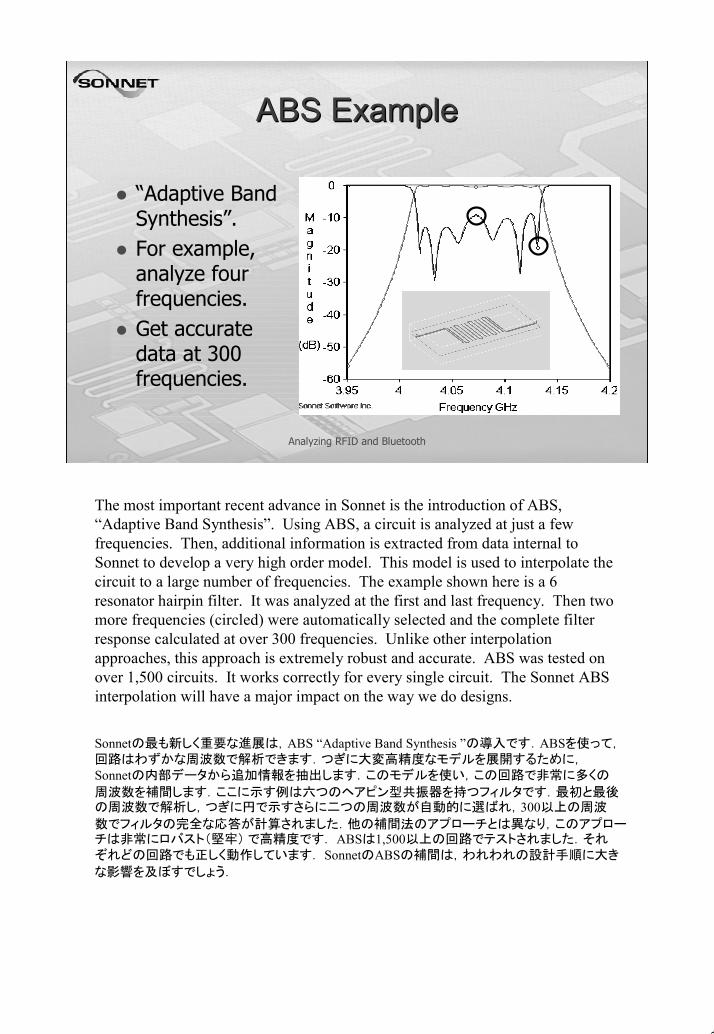
“Adaptive Band Synthesis”.For example, analyze four frequencies.Get accurate data at 300 frequencies.
The most important recent advance in Sonnet is the introduction of ABS, “Adaptive Band Synthesis”. Using ABS, a circuit is analyzed at just a few frequencies. Then, additional information is extracted from data internal to Sonnet to develop a very high order model. This model is used to interpolate the circuit to a large number of frequencies. The example shown here is a 6 resonator hairpin filter. It was analyzed at the first and last frequency. Then two more frequencies (circled) were automatically selected and the complete filter response calculated at over 300 frequencies. Unlike other interpolation approaches, this approach is extremely robust and accurate. ABS was tested on over 1,500 circuits. It works correctly for every single circuit. The Sonnet ABS interpolation will have a major impact on the way we do designs.
Sonnetの最も新しく重要な進展は,ABS “Adaptive Band Synthesis ”の導入です.ABSを使って,回路はわずかな周波数で解析できます.つぎに大変高精度なモデルを展開するために,Sonnetの内部データから追加情報を抽出します.このモデルを使い,この回路で非常に多くの
周波数を補間します.ここに示す例は六つのヘアピン型共振器を持つフィルタです.最初と最後の周波数で解析し,つぎに円で示すさらに二つの周波数が自動的に選ばれ,300以上の周波
数でフィルタの完全な応答が計算されました.他の補間法のアプローチとは異なり,このアプローチは非常にロバスト(堅牢) で高精度です. ABSは1,500以上の回路でテストされました.それぞれどの回路でも正しく動作しています. SonnetのABSの補間は,われわれの設計手順に大き
な影響を及ぼすでしょう.

4
Analyzing RFID and Bluetooth
RFID ApplicationsRFID ApplicationsUseful for tracking equipment, goods, animals, etc.No need to see the tag to read it.Good for very severe environments.No internal power needed.Extremely durable.
Texas Instruments “Tag-It”Can be laminated into
tags, cards, etc.
RFID has become popular over the last few years for tracking equipment, goods, animals, etc. One of the most popular forms of RFID is shown here. Operating at 13.56 MHz, the “tag” coil draws power from the RF energy radiated by a “reader” coil. Then, the IC on the RFID tag alternately resonates and de-tunes the tag coil, thus modulating the tightly coupled reader coil with data stored in the tag IC. While one must see a bar code in order to read it, an RFID can be read even though it is hidden. It can be used in snow, rain, and heat with no problem. Since all power is supplied by the reader, the tag does not need a battery. The tags are extremely durable, often lasting longer than the equipment that they tag.
RFIDはここ数年,装置,商品,動物などの追跡に使われるようになりました.最もポピュラーな
RFIDをここに示します.13.56MHzで動作し, “tag” コイルは“reader” コイルが放射した高周波
エネルギーから電力を引き込みます.つぎに,RFIDタグ上のICは交互にタグコイルを共振・離調し,リーダコイルに密に結合して,タグICに記憶されているデータで変調します.バーコードは見えているコードを読みますが,RFIDは隠れていても読めます.雪,雨や暑いころでも問題あり
ません.電力はすべてリーダから供給されるので,タグはバッテリが要りません.タグは耐久性に優れ,タグを付けた装置より耐久力があるくらいです.
5
Analyzing RFID and Bluetooth
RFID InductorRFID Inductor
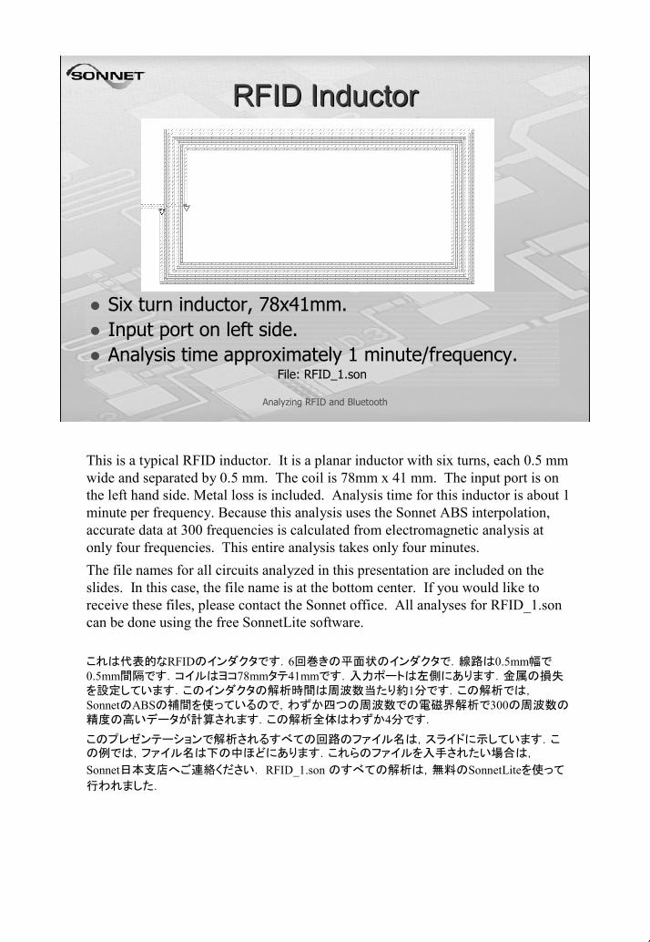
Six turn inductor, 78x41mm.Input port on left side.Analysis time approximately 1 minute/frequency.
File: RFID_1.son
This is a typical RFID inductor. It is a planar inductor with six turns, each 0.5 mm wide and separated by 0.5 mm. The coil is 78mm x 41 mm. The input port is on the left hand side. Metal loss is included. Analysis time for this inductor is about 1 minute per frequency. Because this analysis uses the Sonnet ABS interpolation, accurate data at 300 frequencies is calculated from electromagnetic analysis at only four frequencies. This entire analysis takes only four minutes.The file names for all circuits analyzed in this presentation are included on the slides. In this case, the file name is at the bottom center. If you would like to receive these files, please contact the Sonnet office. All analyses for RFID_1.son can be done using the free SonnetLite software.
これは代表的なRFIDのインダクタです.6回巻きの平面状のインダクタで.線路は0.5mm幅で0.5mm間隔です.コイルはヨコ78mmタテ41mmです.入力ポートは左側にあります.金属の損失を設定しています.このインダクタの解析時間は周波数当たり約1分です.この解析では,SonnetのABSの補間を使っているので,わずか四つの周波数での電磁界解析で300の周波数の精度の高いデータが計算されます.この解析全体はわずか4分です.
このプレゼンテーションで解析されるすべての回路のファイル名は,スライドに示しています.この例では,ファイル名は下の中ほどにあります.これらのファイルを入手されたい場合は,
Sonnet日本支店へご連絡ください. RFID_1.son のすべての解析は,無料のSonnetLiteを使って
行われました.
6
Analyzing RFID and Bluetooth
RFID InductorRFID Inductor
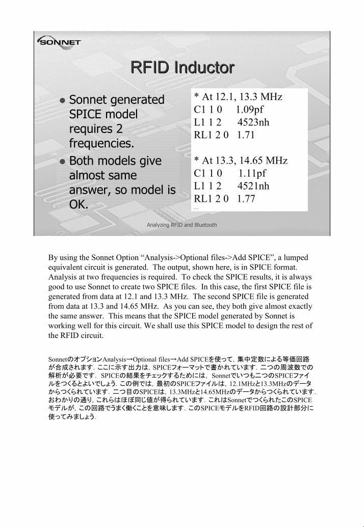
Sonnet generated SPICE model requires 2 frequencies.Both models give almost same answer, so model is OK.
* At 12.1, 13.3 MHzC1 1 0 1.09pfL1 1 2 4523nhRL1 2 0 1.71
* At 13.3, 14.65 MHzC1 1 0 1.11pfL1 1 2 4521nhRL1 2 0 1.77…
By using the Sonnet Option “Analysis->Optional files->Add SPICE”, a lumped equivalent circuit is generated. The output, shown here, is in SPICE format. Analysis at two frequencies is required. To check the SPICE results, it is always good to use Sonnet to create two SPICE files. In this case, the first SPICE file is generated from data at 12.1 and 13.3 MHz. The second SPICE file is generated from data at 13.3 and 14.65 MHz. As you can see, they both give almost exactly the same answer. This means that the SPICE model generated by Sonnet is working well for this circuit. We shall use this SPICE model to design the rest of the RFID circuit.
SonnetのオプションAnalysis→Optional files→Add SPICEを使って,集中定数による等価回路が合成されます.ここに示す出力は,SPICEフォーマットで書かれています.二つの周波数での解析が必要です. SPICEの結果をチェックするためには, Sonnetでいつも二つのSPICEファイルをつくるとよいでしょう.この例では,最初のSPICEファイルは,12.1MHzと13.3MHzのデータからつくられています.二つ目のSPICEは,13.3MHzと14.65MHzのデータからつくられています.おわかりの通り,これらはほぼ同じ値が得られています.これはSonnetでつくられたこのSPICEモデルが,この回路でうまく働くことを意味します.このSPICEモデルをRFID回路の設計部分に
使ってみましょう.
7
Analyzing RFID and Bluetooth
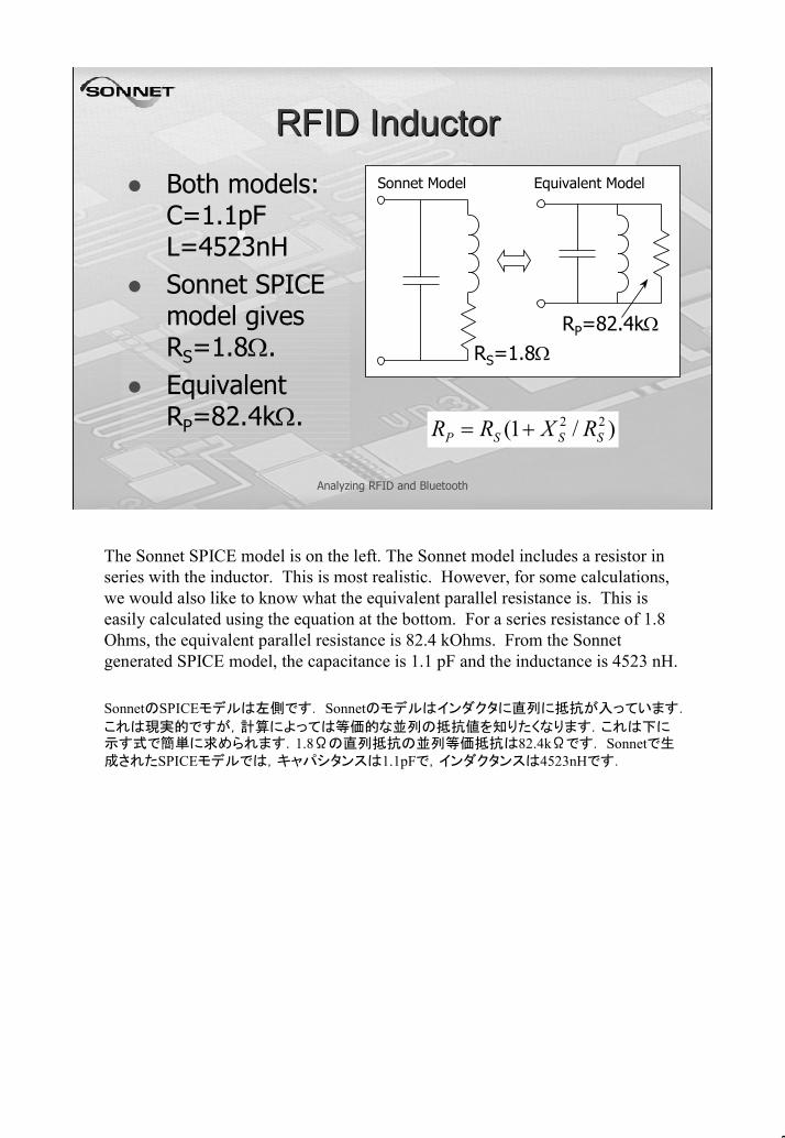
RFID InductorRFID InductorBoth models: C=1.1pF L=4523nHSonnet SPICE model gives RS=1.8Ω.Equivalent RP=82.4kΩ.
Sonnet Model Equivalent Model
RS=1.8ΩRP=82.4kΩ
)/1( 22SSSP RXRR +=
The Sonnet SPICE model is on the left. The Sonnet model includes a resistor in series with the inductor. This is most realistic. However, for some calculations, we would also like to know what the equivalent parallel resistance is. This is easily calculated using the equation at the bottom. For a series resistance of 1.8 Ohms, the equivalent parallel resistance is 82.4 kOhms. From the Sonnet generated SPICE model, the capacitance is 1.1 pF and the inductance is 4523 nH.
SonnetのSPICEモデルは左側です. Sonnetのモデルはインダクタに直列に抵抗が入っています.
これは現実的ですが,計算によっては等価的な並列の抵抗値を知りたくなります.これは下に示す式で簡単に求められます.1.8Ωの直列抵抗の並列等価抵抗は82.4kΩです. Sonnetで生成されたSPICEモデルでは,キャパシタンスは1.1pFで,インダクタンスは4523nHです.
8
Analyzing RFID and Bluetooth
Attaching the RFID ICAttaching the RFID ICThe RFID IC has 23.5pF capacitance.The inductor has 1.1pF capacitance.Total of 30.5pF need to resonate inductor at 13.56 MHz.So…we must add 5.9pF external capacitance: 23.5 + 1.1 + 5.9 = 30.5 pF
The RFID IC we wish to use has a total of 23.5 pF of internal capacitance. The inductor, as calculated by the Sonnet SPICE model, already has 1.1 pF of capacitance. In order to make a 4523 nH coil resonant at 13.56 MHz, we need a total of 30.5 pF. Thus, we must add an external capacitor of 5.9 pF to tune the inductor to 13.56 MHz when it is connected to the RFID IC.
使おうとしているRFIDのICの内部キャパシタンスの合計は23.5pFです. SonnetのSPICEモデルで既に計算されたインダクタには,1.1pFのキャパシタがあります.13.56MHzで共振する4325nHのコイルをつくるためには,合計30.5pFが必要です.従って, RFIDのICに接続されるときには,インダクタを13.56MHzに調整するには,5.9pFのキャパシタを追加しなければなりませ
ん.
9
Analyzing RFID and Bluetooth
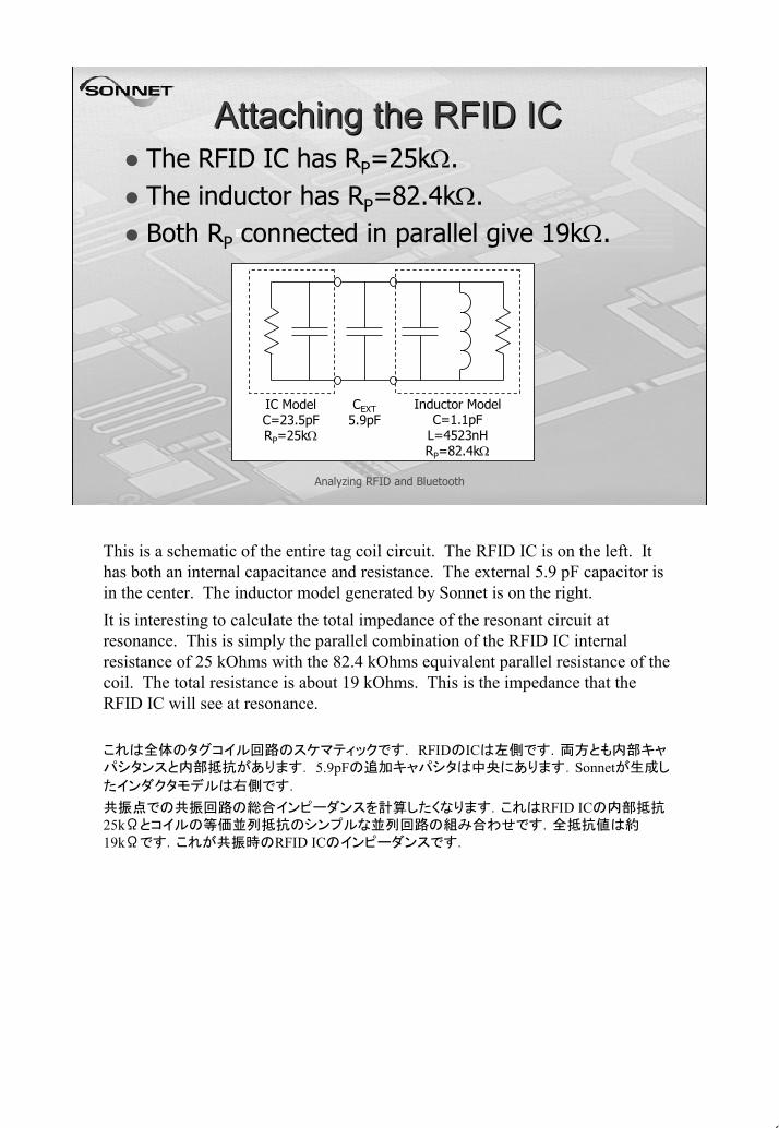
Attaching the RFID ICAttaching the RFID ICThe RFID IC has RP=25kΩ.The inductor has RP=82.4kΩ.Both RP connected in parallel give 19kΩ.
Inductor ModelC=1.1pF
L=4523nHRP=82.4kΩ
IC ModelC=23.5pFRP=25kΩ
CEXT5.9pF
This is a schematic of the entire tag coil circuit. The RFID IC is on the left. It has both an internal capacitance and resistance. The external 5.9 pF capacitor is in the center. The inductor model generated by Sonnet is on the right.It is interesting to calculate the total impedance of the resonant circuit at resonance. This is simply the parallel combination of the RFID IC internal resistance of 25 kOhms with the 82.4 kOhms equivalent parallel resistance of the coil. The total resistance is about 19 kOhms. This is the impedance that the RFID IC will see at resonance.
これは全体のタグコイル回路のスケマティックです. RFIDのICは左側です.両方とも内部キャパシタンスと内部抵抗があります. 5.9pFの追加キャパシタは中央にあります.Sonnetが生成し
たインダクタモデルは右側です.
共振点での共振回路の総合インピーダンスを計算したくなります.これはRFID ICの内部抵抗25kΩとコイルの等価並列抵抗のシンプルな並列回路の組み合わせです.全抵抗値は約19kΩです.これが共振時のRFID ICのインピーダンスです.
10
Analyzing RFID and Bluetooth
Analyze the Inductor and ICAnalyze the Inductor and ICUse any nodal analysis.Use Sonnet data directly for the inductor.Can be done using Sonnet’s nodal analysis:
CAP 1 C=23.5 ; RFID IC ModelRES 1 R=25000 ; RFID IC ModelCAP 1 C=5.9 ; External CapacitorPRJ 1 0 RFID_1.son Use sweep from RFID_1.son
DEF1P 1 Net Main This line includes the Sonnet EM inductor data, automatically re-analyzed only if needed.
This line includes the Sonnet EM inductor data, automatically re-analyzed only if needed.
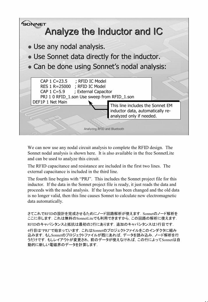
We can now use any nodal circuit analysis to complete the RFID design. The Sonnet nodal analysis is shown here. It is also available in the free SonnetLite and can be used to analyze this circuit.The RFID capacitance and resistance are included in the first two lines. The external capacitance is included in the third line.The fourth line begins with “PRJ”. This includes the Sonnet project file for this inductor. If the data in the Sonnet project file is ready, it just reads the data and proceeds with the nodal analysis. If the layout has been changed and the old data is no longer valid, then this line causes Sonnet to calculate new electromagnetic data automatically.
さてこれでRFIDの設計を完成させるためにノード回路解析が使えます.Sonnetのノード解析をここに示します.これは無料のSonnetLiteでも利用できますから,この回路の解析に使えます.
RFIDのキャパシタンスと抵抗は最初の2行にあります.追加のキャパシタンスは3行目です.
4行目は“PRJ”で始まっています.これはSonnetのプロジェクトファイルをこのインダクタに組み込みます.もしSonnetのプロジェクトファイルが既にあれば,データを読み込み,ノード解析を行うだけです.もしレイアウトが変更され,前のデータが使えなければ,この行によってSonnetは自
動的に新しい電磁界のデータを計算します.
11
Analyzing RFID and Bluetooth
Analyze the Inductor and ICAnalyze the Inductor and ICResonance is at 13.56MHz,Total impedance is almost 19kΩ.Z-param plotted.File: RFID_1_net.son
Imag
Mag
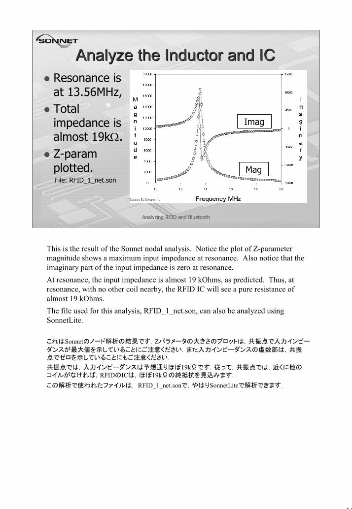
This is the result of the Sonnet nodal analysis. Notice the plot of Z-parameter magnitude shows a maximum input impedance at resonance. Also notice that the imaginary part of the input impedance is zero at resonance.At resonance, the input impedance is almost 19 kOhms, as predicted. Thus, at resonance, with no other coil nearby, the RFID IC will see a pure resistance of almost 19 kOhms.The file used for this analysis, RFID_1_net.son, can also be analyzed using SonnetLite.
これはSonnetのノード解析の結果です.Zパラメータの大きさのプロットは,共振点で入力インピー
ダンスが最大値を示していることにご注意ください.また入力インピーダンスの虚数部は,共振点でゼロを示していることにもご注意ください.
共振点では,入力インピーダンスは予想通りほぼ19kΩです.従って,共振点では,近くに他のコイルがなければ,RFIDのICは,ほぼ19kΩの純抵抗を見込みます.
この解析で使われたファイルは, RFID_1_net.sonで,やはりSonnetLiteで解析できます.
12
Analyzing RFID and Bluetooth
Inductor FieldsInductor FieldsTo see E-fields, use “sense layer”.2-D E-field is “core” of 3-D B-field.3-D B-field “wraps around” the tangential E-Field. File: RFID_2.son
E-Field
B-Field
35 mm above coil25 mm above coil
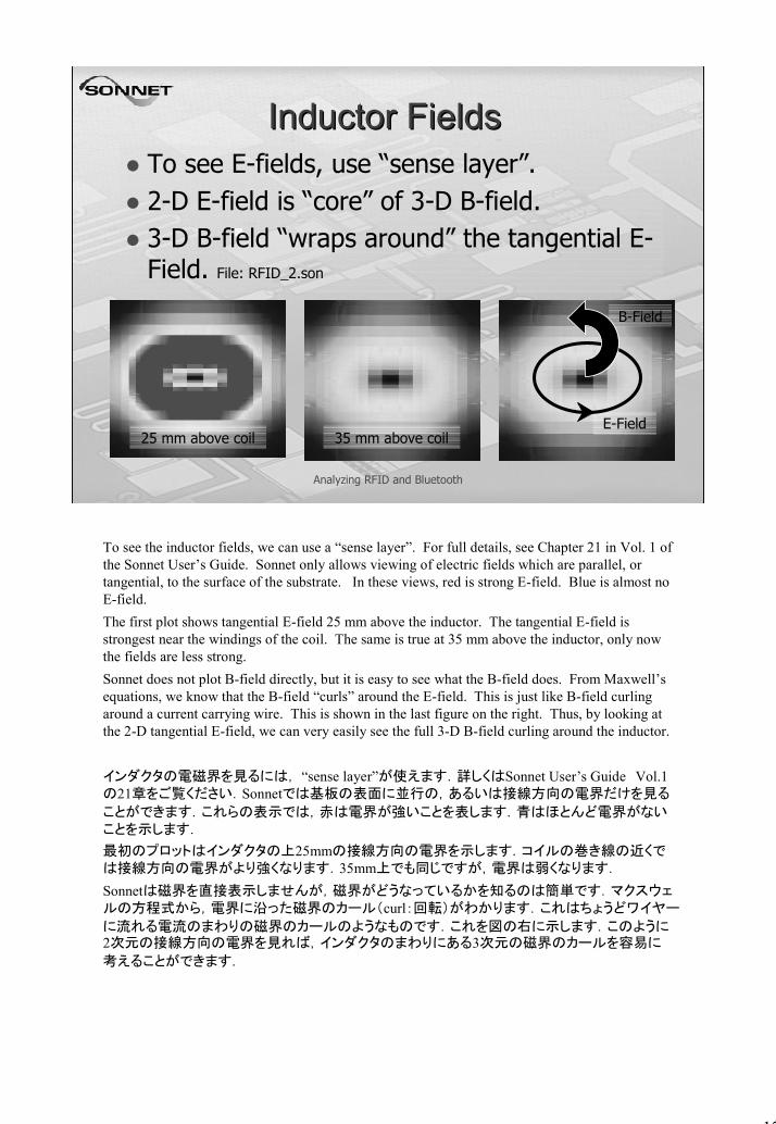
To see the inductor fields, we can use a “sense layer”. For full details, see Chapter 21 in Vol. 1 of the Sonnet User’s Guide. Sonnet only allows viewing of electric fields which are parallel, or tangential, to the surface of the substrate. In these views, red is strong E-field. Blue is almost no E-field.The first plot shows tangential E-field 25 mm above the inductor. The tangential E-field is strongest near the windings of the coil. The same is true at 35 mm above the inductor, only now the fields are less strong.Sonnet does not plot B-field directly, but it is easy to see what the B-field does. From Maxwell’s equations, we know that the B-field “curls” around the E-field. This is just like B-field curling around a current carrying wire. This is shown in the last figure on the right. Thus, by looking at the 2-D tangential E-field, we can very easily see the full 3-D B-field curling around the inductor.
インダクタの電磁界を見るには, “sense layer”が使えます.詳しくはSonnet User’s Guide Vol.1の21章をご覧ください.Sonnetでは基板の表面に並行の,あるいは接線方向の電界だけを見る
ことができます.これらの表示では,赤は電界が強いことを表します.青はほとんど電界がないことを示します.
最初のプロットはインダクタの上25mmの接線方向の電界を示します.コイルの巻き線の近くでは接線方向の電界がより強くなります.35mm上でも同じですが,電界は弱くなります.
Sonnetは磁界を直接表示しませんが,磁界がどうなっているかを知るのは簡単です.マクスウェルの方程式から,電界に沿った磁界のカール(curl:回転)がわかります.これはちょうどワイヤー
に流れる電流のまわりの磁界のカールのようなものです.これを図の右に示します.このように2次元の接線方向の電界を見れば,インダクタのまわりにある3次元の磁界のカールを容易に
考えることができます.
13
Analyzing RFID and Bluetooth
Entire Model in SonnetEntire Model in SonnetMost accurate to have ports at box edge.Perfect ground at box edge.Connecting line is de-embedded.
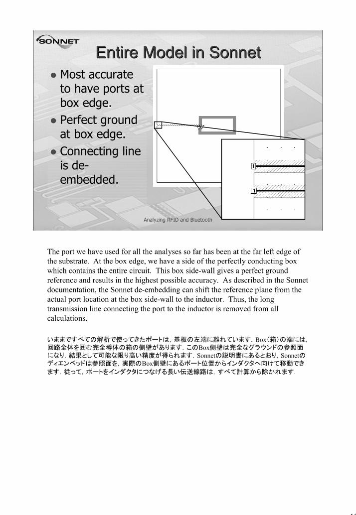
The port we have used for all the analyses so far has been at the far left edge of the substrate. At the box edge, we have a side of the perfectly conducting box which contains the entire circuit. This box side-wall gives a perfect ground reference and results in the highest possible accuracy. As described in the Sonnet documentation, the Sonnet de-embedding can shift the reference plane from the actual port location at the box side-wall to the inductor. Thus, the long transmission line connecting the port to the inductor is removed from all calculations.
いままですべての解析で使ってきたポートは,基板の左端に離れています.Box(箱)の端には,回路全体を囲む完全導体の箱の側壁があります.このBox側壁は完全なグラウンドの参照面になり,結果として可能な限り高い精度が得られます.Sonnetの説明書にあるとおり,Sonnetのディエンベッドは参照面を,実際のBox側壁にあるポート位置からインダクタへ向けて移動でき
ます.従って,ポートをインダクタにつなげる長い伝送線路は,すべて計算から除かれます.
14
Analyzing RFID and Bluetooth
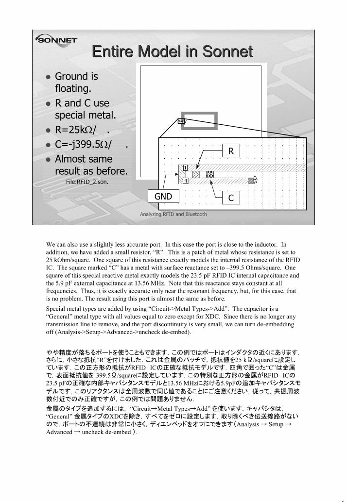
Entire Model in SonnetEntire Model in SonnetGround is floating.R and C use special metal.R=25kΩ/.C=-j399.5Ω/ .Almost same result as before.
File:RFID_2.son.
GND
R
C
We can also use a slightly less accurate port. In this case the port is close to the inductor. In addition, we have added a small resistor, “R”. This is a patch of metal whose resistance is set to 25 kOhm/square. One square of this resistance exactly models the internal resistance of the RFID IC. The square marked “C” has a metal with surface reactance set to –399.5 Ohms/square. One square of this special reactive metal exactly models the 23.5 pF RFID IC internal capacitance and the 5.9 pF external capacitance at 13.56 MHz. Note that this reactance stays constant at all frequencies. Thus, it is exactly accurate only near the resonant frequency, but, for this case, that is no problem. The result using this port is almost the same as before.Special metal types are added by using “Circuit->Metal Types->Add”. The capacitor is a “General” metal type with all values equal to zero except for XDC. Since there is no longer any transmission line to remove, and the port discontinuity is very small, we can turn de-embedding off (Analysis->Setup->Advanced->uncheck de-embed).
やや精度が落ちるポートを使うこともできます.この例ではポートはインダクタの近くにあります.さらに,小さな抵抗“R”を付けました.これは金属のパッチで,抵抗値を25 kΩ/squareに設定しています.この正方形の抵抗がRFID ICの正確な抵抗モデルです.四角で囲った“C”は金属で,表面抵抗値を-399.5Ω/squareに設定しています.この特別な正方形の金属がRFID ICの23.5 pFの正確な内部キャパシタンスモデルと13.56 MHzにおける5.9pFの追加キャパシタンスモ
デルです.このリアクタンスは全周波数で同じ値であることにご注意ください.従って,共振周波数付近でのみ正確ですが,この例では問題ありません.
金属のタイプを追加するには, “Circuit→Metal Types→Add” を使います.キャパシタは,“General” 金属タイプのXDCを除き,すべてをゼロに設定します.取り除くべき伝送線路がないので,ポートの不連続は非常に小さく,ディエンベッドをオフにできます(Analysis → Setup →Advanced → uncheck de-embed ).
15
Analyzing RFID and Bluetooth
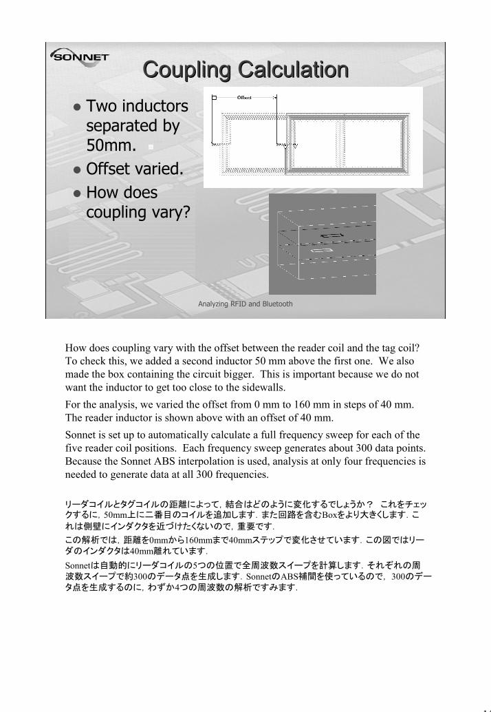
Coupling CalculationCoupling CalculationTwo inductors separated by 50mm.Offset varied.How does coupling vary?
How does coupling vary with the offset between the reader coil and the tag coil? To check this, we added a second inductor 50 mm above the first one. We also made the box containing the circuit bigger. This is important because we do not want the inductor to get too close to the sidewalls.For the analysis, we varied the offset from 0 mm to 160 mm in steps of 40 mm. The reader inductor is shown above with an offset of 40 mm.Sonnet is set up to automatically calculate a full frequency sweep for each of the five reader coil positions. Each frequency sweep generates about 300 data points. Because the Sonnet ABS interpolation is used, analysis at only four frequencies is needed to generate data at all 300 frequencies.
リーダコイルとタグコイルの距離によって,結合はどのように変化するでしょうか? これをチェックするに,50mm上に二番目のコイルを追加します.また回路を含むBoxをより大きくします.こ
れは側壁にインダクタを近づけたくないので,重要です.
この解析では,距離を0mmから160mmまで40mmステップで変化させています.この図ではリーダのインダクタは40mm離れています.
Sonnetは自動的にリーダコイルの5つの位置で全周波数スイープを計算します.それぞれの周波数スイープで約300のデータ点を生成します.SonnetのABS補間を使っているので, 300のデータ点を生成するのに,わずか4つの周波数の解析ですみます.
16
Analyzing RFID and Bluetooth
Coupling CalculationCoupling Calculation
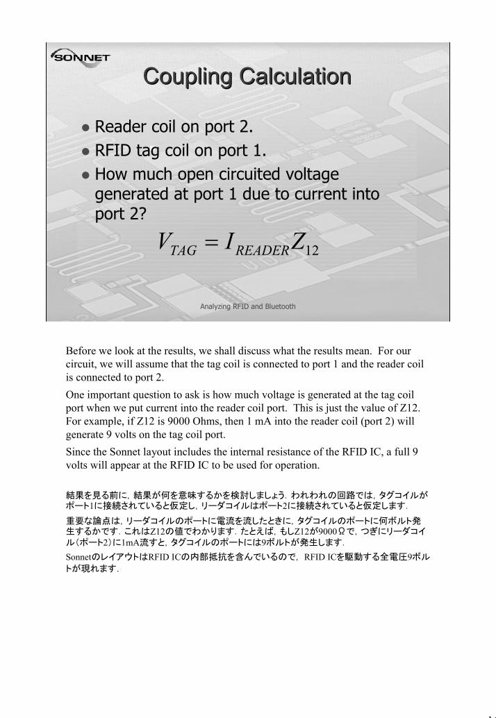
Reader coil on port 2.RFID tag coil on port 1.How much open circuited voltage generated at port 1 due to current into port 2?
12ZIV READERTAG =
Before we look at the results, we shall discuss what the results mean. For our circuit, we will assume that the tag coil is connected to port 1 and the reader coil is connected to port 2.One important question to ask is how much voltage is generated at the tag coil port when we put current into the reader coil port. This is just the value of Z12. For example, if Z12 is 9000 Ohms, then 1 mA into the reader coil (port 2) will generate 9 volts on the tag coil port.Since the Sonnet layout includes the internal resistance of the RFID IC, a full 9 volts will appear at the RFID IC to be used for operation.
結果を見る前に,結果が何を意味するかを検討しましょう.われわれの回路では,タグコイルがポート1に接続されていると仮定し,リーダコイルはポート2に接続されていると仮定します.
重要な論点は,リーダコイルのポートに電流を流したときに,タグコイルのポートに何ボルト発生するかです.これはZ12の値でわかります.たとえば,もしZ12が9000Ωで,つぎにリーダコイル(ポート2)に1mA流すと,タグコイルのポートには9ボルトが発生します.
SonnetのレイアウトはRFID ICの内部抵抗を含んでいるので, RFID ICを駆動する全電圧9ボル
トが現れます.

17
Analyzing RFID and Bluetooth
Coil Coupling Coil Coupling –– Z12Z12
Offset:0 mm40 mm80 mm
We see that for both 0 mm offset and for 40 mm offset, the value of Z12 is just under 9000 Ohms. Thus, the RFID IC will have just under 9 Volts to operate for every 1 mA of current going into the reader coil.The value of Z21 drops off quickly at 80 mm. At this location, the reader coil has just passed beyond the edge of the tag coil. Coupling drops off rapidly. The tag coil now gets only about 2 Volts for every 1 mA flowing into the reader coil.
0mmと40mm離れているときは,Z12の値は9000Ωよりわずか小さい値です.従って,RFID ICはリーダコイルに1mAの電流が流れれば9ボルト近くで動作するでしょう.
Z12の値は80mmでは急に落ち込みます.この位置では,リーダコイルは,タグコイルの端をちょうど越えます.結合は急に落ち込みます.タグコイルは,リーダコイルに1mAの電流が流れても,2ボルト程度しか得られません.
18
Analyzing RFID and Bluetooth
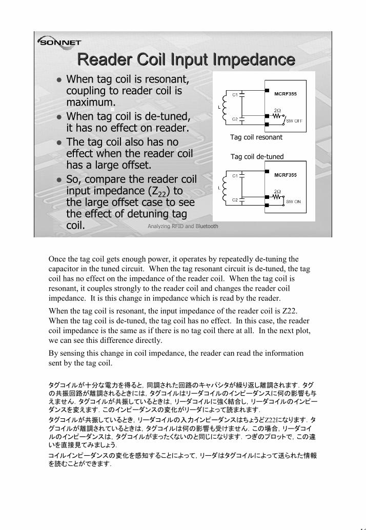
Reader Coil Input ImpedanceReader Coil Input ImpedanceWhen tag coil is resonant, coupling to reader coil is maximum.When tag coil is de-tuned, it has no effect on reader.The tag coil also has no effect when the reader coil has a large offset.So, compare the reader coil input impedance (Z22) to the large offset case to see the effect of detuning tag coil.
Tag coil resonant
Tag coil de-tuned
Once the tag coil gets enough power, it operates by repeatedly de-tuning the capacitor in the tuned circuit. When the tag resonant circuit is de-tuned, the tag coil has no effect on the impedance of the reader coil. When the tag coil is resonant, it couples strongly to the reader coil and changes the reader coil impedance. It is this change in impedance which is read by the reader.When the tag coil is resonant, the input impedance of the reader coil is Z22. When the tag coil is de-tuned, the tag coil has no effect. In this case, the reader coil impedance is the same as if there is no tag coil there at all. In the next plot, we can see this difference directly.By sensing this change in coil impedance, the reader can read the information sent by the tag coil.
タグコイルが十分な電力を得ると,同調された回路のキャパシタが繰り返し離調されます.タグの共振回路が離調されるときには,タグコイルはリーダコイルのインピーダンスに何の影響も与えません.タグコイルが共振しているときは,リーダコイルに強く結合し,リーダコイルのインピーダンスを変えます.このインピーダンスの変化がリーダによって読まれます.
タグコイルが共振しているとき,リーダコイルの入力インピーダンスはちょうどZ22になります.タ
グコイルが離調されているときは,タグコイルは何の影響も受けません.この場合,リーダコイルのインピーダンスは,タグコイルがまったくないのと同じになります.つぎのプロットで,この違いを直接見てみましょう.
コイルインピーダンスの変化を感知することによって,リーダはタグコイルによって送られた情報を読むことができます.
19
Analyzing RFID and Bluetooth
Coil Input ImpedanceCoil Input Impedance
Tag coil resonant, but offset:
80 mm40 mm0 mm
Tag coildetuned
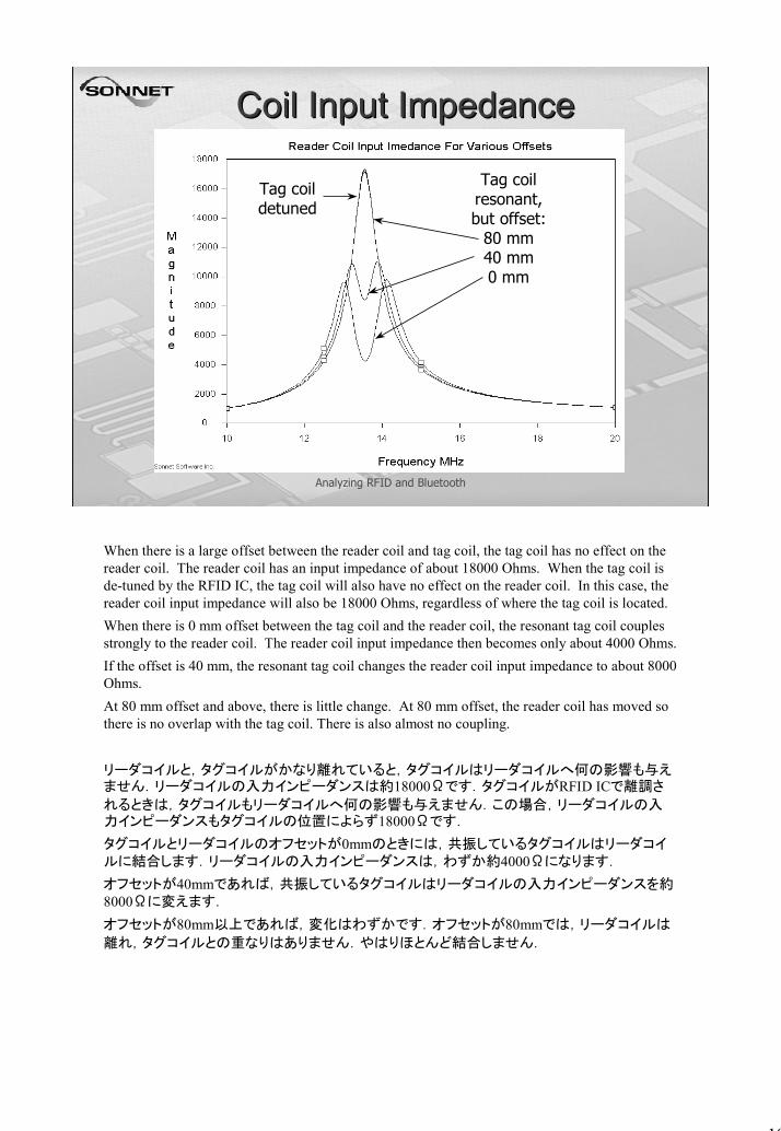
When there is a large offset between the reader coil and tag coil, the tag coil has no effect on the reader coil. The reader coil has an input impedance of about 18000 Ohms. When the tag coil is de-tuned by the RFID IC, the tag coil will also have no effect on the reader coil. In this case, the reader coil input impedance will also be 18000 Ohms, regardless of where the tag coil is located.When there is 0 mm offset between the tag coil and the reader coil, the resonant tag coil couples strongly to the reader coil. The reader coil input impedance then becomes only about 4000 Ohms.If the offset is 40 mm, the resonant tag coil changes the reader coil input impedance to about 8000 Ohms.At 80 mm offset and above, there is little change. At 80 mm offset, the reader coil has moved so there is no overlap with the tag coil. There is also almost no coupling.
リーダコイルと,タグコイルがかなり離れていると,タグコイルはリーダコイルへ何の影響も与えません.リーダコイルの入力インピーダンスは約18000Ωです.タグコイルがRFID ICで離調さ
れるときは,タグコイルもリーダコイルへ何の影響も与えません.この場合,リーダコイルの入力インピーダンスもタグコイルの位置によらず18000Ωです.
タグコイルとリーダコイルのオフセットが0mmのときには,共振しているタグコイルはリーダコイルに結合します.リーダコイルの入力インピーダンスは,わずか約4000Ωになります.
オフセットが40mmであれば,共振しているタグコイルはリーダコイルの入力インピーダンスを約8000Ωに変えます.
オフセットが80mm以上であれば,変化はわずかです.オフセットが80mmでは,リーダコイルは
離れ,タグコイルとの重なりはありません.やはりほとんど結合しません.

20
Analyzing RFID and Bluetooth
Double Reader Coil SizeDouble Reader Coil SizeReader coil (and substrate) now two times bigger.Total additional capacitance is now 8 pF, including RFID IC.How does coupling change as offset varied?
File: RFID_4.son
What happens when the reader coil is doubled in size? This is shown here. As mentioned before, in order to keep high accuracy, we must keep the sides of the box away from the inductor. Thus, we doubled the size of the box for this analysis. Also, because the inductor is larger, a smaller capacitance is needed for resonance. Now a total of only 8 pF is needed.Here, the reader coil is shown offset 40 mm to the right of the small tag coil. Note that at 80 mm offset, the reader coil will no longer overlap any part of the tag coil, and we would expect almost no coupling, just like in the previous case.
リーダコイルの寸法を倍にしたときに何が起こるでしょうか?それをここに示します.前に述べたように,高精度を保つために,Box側壁をインダクタから離しておく必要があります.従って,この解析では,Boxの寸法を倍にします.また,インダクタがより大きくなるので,共振のためのキャパシタンスは小さくなります.合計わずか8pFです.
ここで,リーダコイルは,小さなタグコイルの右に40mm離れています.80mm離すと,リーダコイ
ルはタグコイルのどの部分とも重ならなくなり,前の例のように,ほぼ結合しなくなると予想されることにご注意ください.
21
Analyzing RFID and Bluetooth
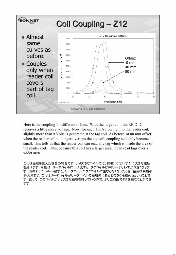
Coil Coupling Coil Coupling –– Z12Z12Almost same curves as before.Couples only when reader coil covers part of tag coil.
Offset:0 mm40 mm80 mm
Here is the coupling for different offsets. With the larger coil, the RFID IC receives a little more voltage. Now, for each 1 mA flowing into the reader coil, slightly more than 9 Volts is generated at the tag coil. As before, at 80 mm offset, when the reader coil no longer overlaps the tag coil, coupling suddenly becomes small. This tells us that the reader coil can read any tag which is inside the area of the reader coil. Thus, because this coil has a larger area, it can read tags over a wider area.
これは距離を変えた場合の結合です.より大きなコイルでは,RFID ICはわずかに大きな電圧を受けます.今度は,リーダコイルに1mA流すと,タグコイルは9ボルトよりわずか大きくなります.前のように,80mm離すと,リーダコイルがタグコイルに重ならなくなったとき,結合は突然小
さくなります.これはリーダコイルがリーダコイルの領域内にあるどのタグも読めるということです.従って,このコイルがより大きな領域を持っているので,より広範囲でタグを読むことができます.

22
Analyzing RFID and Bluetooth
Coil Input ImpedanceCoil Input Impedance
Offset:80 mm40 mm0 mm
As before, we can see how much the input impedance of the reader coil changes from when the tag is resonant to when the tag is de-tuned. The peak of the curve is the reader coil input impedance when the tag coil has no effect. This is the same thing as the tag coil being de-tuned. Thus, when the tag coil is de-tuned, it will have an input impedance of about 21000 Ohms. At 0 mm offset, the resonant tag coil will cause the reader coil input impedance to drop to about 6000 Ohms.
すでに述べたように,タグコイルが離調されたときと,つぎに共振したとき,リーダコイルの入力インピーダンスがどれだけ変わるかを見ることができます.カーブのピークはタグコイルが影響を与えていない位置です.タグコイルが離調されているのと同じです.従って,タグコイルが離調されているときは,入力インピーダンスは21000Ωになります.距離が0mmでは,共振しているタグコイルはリーダコイルの入力インピーダンスを約6000Ωに落とすでしょう.

23
Analyzing RFID and Bluetooth
Bluetooth AntennaBluetooth AntennaPosition of via port adjusted for best match.Four ABS frequencies for full sweep.30 Sec/freq.File: BT_1.son
Via port input under
antenna.
Bluetooth normally operates from 2.402 to 2.480 GHz. This is a special, compact Bluetooth antenna. The wide strip is a long patch antenna a little bit like a dipole. The feed point is from a via underneath the antenna as shown. The position of the via is adjusted for a good input impedance match. The length of the patch is adjusted to get the desired resonance. For a slightly faster analysis, port de-embedding is turned off (Analysis->Setup->Advanced->uncheck de-embed).Analysis time for this antenna is 26 seconds per frequency on a 1.3 GHz Pentium. The Sonnet ABS interpolation requires only four frequencies to calculate all 300 frequencies across the band. This means only 2 minutes for a complete analysis. Such a short time for analysis is important. This means one can evaluate many different design changes to quickly find the best design.
Bluetoothは通常2.402 から 2.480 GHzで動作します.これは特に小型のBluetoothアンテナです.
幅の広い帯で,ダイポールに似た長いパッチアンテナを形成しています.ここに示すようにアンテナの下からviaで給電されています.Viaの位置は入力インピーダンスの整合を取るために調整さ
れています.所望の共振を得るにはパッチの長さを調整します.少し早く解析するには,ポートのディエンベッドをオフにします( Analysis→Setup → Advanced → uncheck de-embed )
このアンテナの解析時間は1.3 GHz Pentiumで周波数当たり26秒です.SonnetのABS補間では,バンドに渡る300周波数の計算のためにわずか4周波数を必要とするだけです.これは完全な解析に2分しかかからないということです.多くの設計変更を評価し,もっともよい設計値をすばやく
見つけられます.
24
Analyzing RFID and Bluetooth
Bluetooth AntennaBluetooth Antenna
2.42 GHz
20 MHz
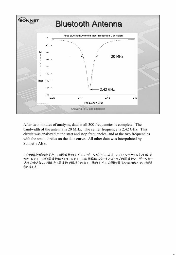
After two minutes of analysis, data at all 300 frequencies is complete. The bandwidth of the antenna is 20 MHz. The center frequency is 2.42 GHz. This circuit was analyzed at the start and stop frequencies, and at the two frequencies with the small circles on the data curve. All other data was interpolated by Sonnet’s ABS.
2分の解析が終わると,300周波数のすべてのデータがそろいます.このアンテナのバンド幅は20MHzです.中心周波数は2.42GHzです.この回路はスタートとストップの周波数と,データカーブ状の小さな丸で示した2周波数で解析されます.他のすべての周波数はSonnetのABSで補間
されました.

25
Analyzing RFID and Bluetooth
Modified Bluetooth AntennaModified Bluetooth Antenna
“F-feed” for wide bandwidth.Two feed points in parallel.
File: BT_2.son“Denjikai simulator de manabu Wireless
no sekai”, Chapter 10, Hiroaki Kogure, CQ Publishing, 2001
It would be convenient to have a wider bandwidth antenna without making the antenna much larger. This can be done with an “F-feed” as shown. The F-feed has two feed points connected in parallel. The port is in a via directly under the dark green rectangle in the magnified picture. Working together, the two feed points allow a wider bandwidth antenna.
アンテナを大きくせずにより広いバンド幅が得られると便利です.これはここに示すような“F-給電”で実現できます.F-給電は,並列に接続された二つの給電点があります.ポートは,拡大図の濃い緑色の矩形の直下のviaにあります.これらが同時に働き,二つの給電点で広いバンド
幅のアンテナになっています.
26
Analyzing RFID and Bluetooth
Modified Bluetooth AntennaModified Bluetooth Antenna
2.425 GHz
35 MHz
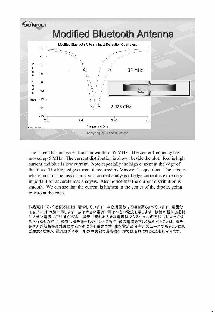
The F-feed has increased the bandwidth to 35 MHz. The center frequency has moved up 5 MHz. The current distribution is shown beside the plot. Red is high current and blue is low current. Note especially the high current at the edge of the lines. The high edge current is required by Maxwell’s equations. The edge is where most of the loss occurs, so a correct analysis of edge current is extremely important for accurate loss analysis. Also notice that the current distribution is smooth. We can see that the current is highest in the center of the dipole, going to zero at the ends.
F-給電はバンド幅を35MHzに増やしています.中心周波数は5MHz高くなっています.電流分
布をプロットの脇に示します.赤は大きい電流,青は小さい電流を示します.線路の縁にある特に大きい電流にご注意ください.縁部に流れる大きな電流はマクスウェルの方程式によって求められるものです.縁部は損失を生じやすいところで,縁の電流を正しく解析することは,損失を含んだ解析を高精度にするために最も重要です.また電流の分布がスムースであることにもご注意ください.電流はダイポールの中央部で最も強く,端ではゼロになることもわかります.

27
Analyzing RFID and Bluetooth
ConclusionConclusionSonnet’s new ABS interpolation is important for fast analysis.RFID is easily analyzed using Sonnet.Capacitance required for resonance is easily calculated.Effect of moving the reader coil is easily calculated.Different Bluetooth antennas are quickly calculated.
In conclusion, we have demonstrated the use of Sonnet’s new ABS interpolation. ABS generates accurate results at over 300 frequencies after a full EM analysis at just a few frequencies. In fact all the EM analyses in this presentation were done with only four analyses per complete frequency sweep.We have shown how Sonnet’s EM and nodal analyses can be used to easily analyze RFID coils. We precisely calculated the additional capacitance required. We also included metal loss and evaluated how the coupling between the RFID reader and tag change as the reader coil is moved.Finally we looked at several Bluetooth antennas. The Sonnet ABS allows very fast analysis so that many different designs can be quickly evaluated. We showed a modified design using an “F-feed”which increases the bandwidth from 20 MHz to 35 MHz.The Sonnet analysis allows a designer to quickly and confidently find the best design for RFID, Bluetooth, and for many other applications. Thank you for listening.
Sonnetの新しいABS補間をご覧いただきました.ABSはわずかな周波数の電磁界解析のあとで,300以上の高精度の結果を出します.実際このプレゼンテーションの電磁界解析はわずか4つの
周波数スイープで行われました.
SonnetのEMとノード解析を使ってどのようにRFIDコイルを容易に解析するかについてご覧いた
だきました.追加する必要があるキャパシタンスを細かく計算しました.また金属の損失を含み,RFIDのリーダコイルを移動するにつれてリーダとタグ間の結合がどのように変化するかも評価し
ました.
最後にBluetooth を調べました.SonnetのABSは大変高速な解析を可能にし,その結果多くの異なった設計を素早く評価できます.F-給電を使ってバンド幅を20 MHz から 35 MHzへ広げる設計
の改良を示しました.
Sonnetの解析は, RFID, Bluetoothや多くのアプリケーションの最適設計を,素早く自信を持って
見いだすことを可能にします. ご静聴ありがとうございました.
28
製品版とLite版の違い
石飛Sonnet Software, Inc.日本支店
November, 2002
無料のSonnet Liteは、現実の多くの問題を解き、実験や試作前に問題の傾向を知り、設計開発
の様々な場面で役立ちます。
Sonnet Liteを使い込み、マニュアルを調べて少しでも大きな問題を効率よく解くことができるようになれば、製品版のSonnetを導入したときに投資を無駄にせず直ちに高価を発揮できるように
なることでしょう。

29
Analyzing RFID and Bluetooth
LiteLite版の版のportport構造構造
Edge portのみ
Lite版ではEdgeポートのみが許されています。
この例ではスパイラルインダクタからEdgeポートへ接続する線路を解析結果から取り除くためにDe-EmbeddingとRefference Planeの移動を行いました。
このDe-EmbeddingとRefference Planeの移動はSonnetだけでなく、他のシミュレータや高周波測
定に欠くことのできない重要な概念です。
SonnetLiteでこれらのテクニックに習熟することは、実験測定の場でも役立つことでしょう。

30
Analyzing RFID and Bluetooth
製品版の製品版のportport構造構造Internal Port– 同じレイアの導体上にhot
とcold– Level2/Pro.
Via Port– Viaの上下をhotとcold– Level2/Pro
Auto-Grounded Port– 導体の任意の位置とgnd– Pro.のみ
GND
R
C
製品版ではより多彩なport構造が許されます。
それらは
* Edge portへ線路を引き出すことが難しい場合
* 引き出し線路の分の解析時間を無視できない場合
* 外付け部品と組み合わせる場合
などに便利な機能ですが、それぞれに長所短所があります。Edge portに習熟していればそれらの新しいportの特徴をなんなく理解して、問題に適したport構造を選択できるようになるまで時
間はかからないでしょう。
31
Analyzing RFID and Bluetooth
Diagonal SubsectionDiagonal Subsection
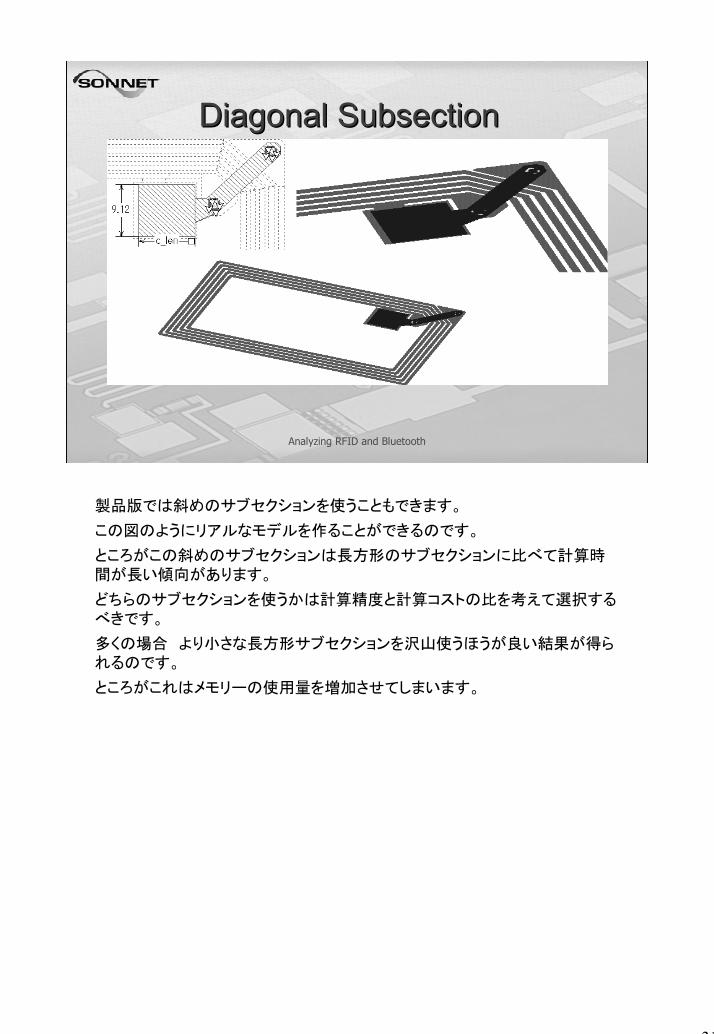
製品版では斜めのサブセクションを使うこともできます。
この図のようにリアルなモデルを作ることができるのです。
ところがこの斜めのサブセクションは長方形のサブセクションに比べて計算時間が長い傾向があります。
どちらのサブセクションを使うかは計算精度と計算コストの比を考えて選択するべきです。
多くの場合 より小さな長方形サブセクションを沢山使うほうが良い結果が得られるのです。
ところがこれはメモリーの使用量を増加させてしまいます。
32
Analyzing RFID and Bluetooth
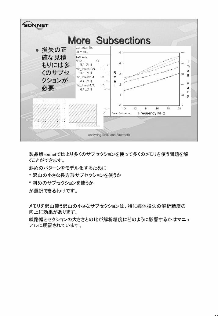
More SubsectionsMore Subsections損失の正確な見積もりには多くのサブセクションが必要
製品版sonnetではより多くのサブセクションを使って多くのメモリを使う問題を解
くことができます。
斜めのパターンをモデル化するために
* 沢山の小さな長方形サブセクションを使うか
* 斜めのサブセクションを使うか
が選択できるわけです。
メモリを沢山使う沢山の小さなサブセクションは、特に導体損失の解析精度の向上に効果があります。
線路幅とセクションの大きさとの比が解析精度にどのように影響するかはマニュアルに明記されています。
33
Analyzing RFID and Bluetooth
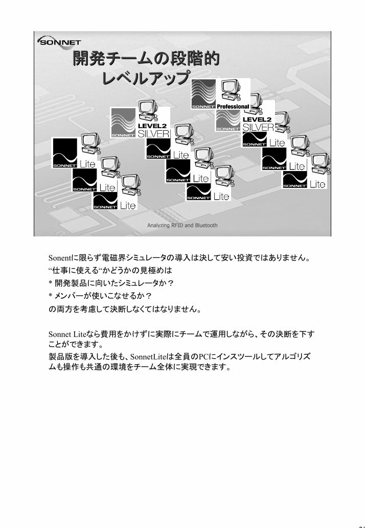
開発チームの段階的開発チームの段階的レベルアップレベルアップ
Sonentに限らず電磁界シミュレータの導入は決して安い投資ではありません。
“仕事に使える“かどうかの見極めは
* 開発製品に向いたシミュレータか?
* メンバーが使いこなせるか?
の両方を考慮して決断しなくてはなりません。
Sonnet Liteなら費用をかけずに実際にチームで運用しながら、その決断を下す
ことができます。
製品版を導入した後も、SonnetLiteは全員のPCにインスツールしてアルゴリズ
ムも操作も共通の環境をチーム全体に実現できます。