Embed Size (px)
Citation preview
User Manual for RCC Series Controller
MAN1020-01-EN

RCC User Manual
Page 2 of 48
PREFACE
This manual explains how to use the RCC Controller. Copyright© 2014 Horner APG, LLC, 59 South State Avenue, Indianapolis, Indiana 46201. All rights reserved. No part of this publication may be reproduced, transmitted, transcribed, stored in a retrieval system, or translated into any language or computer language, in any form by any means, electronic, mechanical, magnetic, optical, chemical, manual or otherwise, without the prior agreement and written permission of Horner APG, Inc. All software described in this document or media is also copyrighted material subject to the terms and conditions of the Horner Software License Agreement. Information in this document is subject to change without notice and does not represent a commitment on the part of Horner APG. Ethernet™ is a trademark of Xerox Corporation. MicroSD™ and CompactFlash are registered trademarks of SanDisk Corporation. For user manual updates, contact Technical Support: North America: Tel: (+) 1-877-665-5666 Fax: (+) (317) 639-4279 Web: http://www.heapg.com Email: [email protected] Europe: Tel: (+) 353-21-4321-266 Fax: (+) 353-21-4321-826 Web: http://www.horner-apg.com Email: [email protected]

MAN2010-01-EN
Page 3 of 48
LIMITED WARRANTY AND LIMITATION OF LIABILITY
Horner APG, LLC, ("HE-APG") warrants to the original purchaser that the RCC controller module manufactured by HE-APG is free from defects in material and workmanship under normal use and service. The obligation of HE-APG under this warranty shall be limited to the repair or exchange of any part or parts which may prove defective under normal use and service within two (2) years from the date of manufacture or eighteen (18) months from the date of installation by the original purchaser whichever occurs first, such defect to be disclosed to the satisfaction of HE-APG after examination by HE-APG of the allegedly defective part or parts. THIS WARRANTY IS EXPRESSLY IN LIEU OF ALL OTHER WARRANTIES EXPRESSED OR IMPLIED INCLUDING THE WARRANTIES OF MERCHANTABILITY AND FITNESS FOR USE AND OF ALL OTHER OBLIGATIONS OR LIABILITIES AND HE-APG NEITHER ASSUMES, NOR AUTHORIZES ANY OTHER PERSON TO ASSUME FOR HE-APG, ANY OTHER LIABILITY IN CONNECTION WITH THE SALE OF THIS RCC module. THIS WARRANTY SHALL NOT APPLY TO THIS RCC module OR ANY PART THEREOF WHICH HAS BEEN SUBJECT TO ACCIDENT, NEGLIGENCE, ALTERATION, ABUSE, OR MISUSE. HE-APG MAKES NO WARRANTY WHATSOEVER IN RESPECT TO ACCESSORIES OR PARTS NOT SUPPLIED BY HE-APG. THE TERM "ORIGINAL PURCHASER", AS USED IN THIS WARRANTY, SHALL BE DEEMED TO MEAN THAT PERSON FOR WHOM THE RCC module IS ORIGINALLY INSTALLED. THIS WARRANTY SHALL APPLY ONLY WITHIN THE BOUNDARIES OF THE CONTINENTAL UNITED STATES. In no event, whether as a result of breach of contract, warranty, tort (including negligence) or otherwise, shall HE-APG or its suppliers be liable of any special, consequential, incidental or penal damages including, but not limited to, loss of profit or revenues, loss of use of the products or any associated equipment, damage to associated equipment, cost of capital, cost of substitute products, facilities, services or replacement power, down time costs, or claims of original purchaser's customers for such damages. To obtain warranty service, return the product to your distributor with a description of the problem, proof of purchase, postpaid, insured and in a suitable package.
ABOUT PROGRAMMING EXAMPLES
Any example programs and program segments in this manual or provided on accompanying diskettes are included solely for illustrative purposes. Due to the many variables and requirements associated with any particular installation, Horner APG cannot assume responsibility or liability for actual use based on the examples and diagrams. It is the sole responsibility of the system designer utilizing the RCC controller module to appropriately design the end system, to appropriately integrate the RCC controller module and to make safety provisions for the end equipment as is usual and customary in industrial applications as defined in any codes or standards which apply.
Note: The programming examples shown in this manual are for illustrative purposes only.
Proper machine operation is the sole responsibility of the system integrator.

MAN2010-01-EN
Page 4 of 48
INTENTIONALLY LEFT BLANK
RCC User Manual
Page 5 of 48
TABLE OF CONTENTS
PREFACE ..................................................................................................................................................... 2
LIMITED WARRANTY AND LIMITATION OF LIABILITY ........................................................................... 3
ABOUT PROGRAMMING EXAMPLES ....................................................................................................... 3
TABLE OF CONTENTS ............................................................................................................................... 5
INTENTIONALLY LEFT BLANK .................................................................................................................. 8
CHAPTER 1 : SAFETY / COMPLIANCE ..................................................................................................... 9 1.1 Safety Warnings and Guidelines .................................................................................................... 9 1.2 Grounding ..................................................................................................................................... 10 1.3 Compliance ................................................................................................................................... 10
CHAPTER 2: INTRODUCTION ................................................................................................................. 11 2.1 Visual Overview of RCC ............................................................................................................... 11
2.1.1 Where to Find Information about the RCC .............................................................................. 11 2.1.2 Four main types of information are covered in this manual ..................................................... 12 2.1.3 Manual Index ......................................................................................................................... 12
2.2 Connectivity to the RCC ............................................................................................................... 12 2.3 Features of RCC ........................................................................................................................... 12 2.4 Required and Suggested Accessories ......................................................................................... 13 2.5 Useful Documents and References .............................................................................................. 13
CHAPTER 3: MECHANICAL INSTALLATION ......................................................................................... 14 3.1 Overview ....................................................................................................................................... 14 3.2 RCC Dimensions .......................................................................................................................... 14
3.6.3 Temperature / Ventilation ...................................................................................................... 15 3.6.4 Orientation ............................................................................................................................. 15 3.6.5 Noise ..................................................................................................................................... 15 3.6.6 Shock and Vibration .............................................................................................................. 15
CHAPTER 4: ELECTRICAL INSTALLATION .......................................................................................... 16 4.1 Grounding Definition ..................................................................................................................... 16 4.2 Ground Specifications................................................................................................................... 16 4.3 How to Test for Good Ground ...................................................................................................... 16 4.4 Primary Power Port ....................................................................................................................... 17
CHAPTER 5: SERIAL COMMUNICATIONS ............................................................................................ 18 5.1 Overview ....................................................................................................................................... 18 5.2 Port Descriptions .......................................................................................................................... 18 5.3 MJ1 Serial Port Pinout .................................................................................................................. 18 5.4 Cscape Programming via Serial Port ........................................................................................... 18 5.5 Ladder-Controlled Serial Communication .................................................................................... 18 5.6 Downloadable Serial Communication Protocols .......................................................................... 18
CHAPTER 6: CAN COMMUNICATIONS ................................................................................................. 19 6.1 Overview ....................................................................................................................................... 19 6.2 Port Description ............................................................................................................................ 19 6.3 CAN Port Wiring ........................................................................................................................... 19 6.4 Cscape Programming via CAN ..................................................................................................... 20 6.5 Ladder-Controlled CAN Communication ...................................................................................... 20 6.6 Using CAN for I/O Expansion (Network I/O) ................................................................................ 20
CHAPTER 7: ETHERNET COMMUNICATION......................................................................................... 21 7.1 Ethernet Module Protocols and Features ..................................................................................... 21 7.2 Ethernet System Requirements .................................................................................................... 21 7.3 Ethernet Module Specifications .................................................................................................... 21
RCC User Manual
Page 6 of 48
7.4 Ethernet Module Configuration ..................................................................................................... 21
CHAPTER 8: REMOVABLE MEDIA ......................................................................................................... 26 8.1 Overview ....................................................................................................................................... 26 8.2 MicroSD Cards ............................................................................................................................. 26 8.3 MicroSD File System .................................................................................................................... 26 8.4 Using Removable Media to Log Data ........................................................................................... 27 8.5 Using Removable Media to Load and Save Applications ............................................................ 27 8.6 Removable Media (RM) Function Blocks in Cscape .................................................................... 27 8.7 Filenames used with the Removable Media (RM) Function Blocks ............................................. 27 8.8 System Registers used with RM ................................................................................................... 28
CHAPTER 9: GENERAL I/O ..................................................................................................................... 29 9.1 Overview ....................................................................................................................................... 29 9.2 Solid-State Digital Outputs ........................................................................................................... 29 9.3 Digital Inputs ................................................................................................................................. 30 9.4 Analog Inputs ................................................................................................................................ 30
9.4.1 Common cause of analog input tranzorb failure. ........................................................................ 31 9.5 Analog Outputs ............................................................................................................................. 31
CHAPTER 10: CSCAPE CONFIGURATION ............................................................................................ 32 10.1 Overview ....................................................................................................................................... 32 10.2 Cscape Status Bar ........................................................................................................................ 32 10.3 Establishing Communications ...................................................................................................... 33
10.3.1 Communicating via MJ1 Serial Port ......................................................................................... 35 10.3.2 Communicating via On Board Ethernet Port ............................................................................ 35
10.4 Configuration ................................................................................................................................ 37
CHAPTER 11: REGISTERS ....................................................................................................................... 39 11.1 Register Definitions....................................................................................................................... 39 11.2 Useful %S and %SR registers ...................................................................................................... 39 11.3 Register Map for RCC I/O ............................................................................................................ 42 11.4 Resource Limits ............................................................................................................................ 42
CHAPTER 12: MAINTENANCE ................................................................................................................ 43 12.1 Firmware Updates ........................................................................................................................ 43
CHAPTER 13: TROUBLESHOOTING / TECHNICAL SUPPORT ............................................................ 43
LED - NORMAL FUNCTIONALITY ............................................................................................................ 43 13.1 Connecting to the RCC ................................................................................................................. 44
13.1.1 Connecting Troubleshooting Checklist (serial port – MJ1 Programming) ............................. 44 13.1.2 Connecting Troubleshooting Checklist (ETN port programming) ......................................... 45
13.2 Local Controller and Local I/O ...................................................................................................... 45 13.3 CsCAN Network ............................................................................................................................ 45
13.3.1 CsCAN Network Troubleshooting Checklist .......................................................................... 45 13.4 Removable Media - Basic Troubleshooting .................................................................................. 46 13.5 Technical Support Contacts ......................................................................................................... 46 Main Index ............................................................................................................................................... 47
RCC User Manual
Page 7 of 48
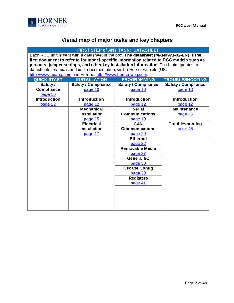
Visual map of major tasks and key chapters
FIRST STEP of ANY TASK: DATASHEET
Each RCC unit is sent with a datasheet in the box. The datasheet (MAN0971-02-EN) is the first document to refer to for model-specific information related to RCC models such as pin-outs, jumper settings, and other key installation information. To obtain updates to datasheets, manuals and user documentation, visit a Horner website (US: http://www.heapg.com and Europe: http://www.horner-apg.com.)
QUICK START INSTALLATION PROGRAMMING TROUBLESHOOTING
Safety / Compliance
page 10
Safety / Compliance page 10
Safety / Compliance page 10
Safety / Compliance page 10
Introduction page 12
Introduction page 12
Introduction page 12
Introduction page 12
Mechanical Installation
page 15
Serial Communications
page 19
Maintenance page 45
Electrical Installation
page 17
CAN Communications
page 20
Troubleshooting page 45
Ethernet page 22
Removable Media page 27
General I/O page 30
Cscape Config page 33
Registers page 41

RCC User Manual
Page 8 of 48
INTENTIONALLY LEFT BLANK
RCC User Manual
Page 9 of 48
CHAPTER 1: SAFETY / COMPLIANCE
1.1 Safety Warnings and Guidelines
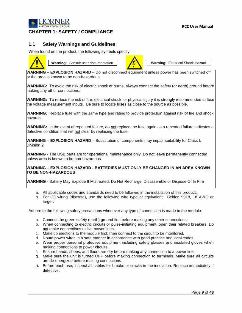
When found on the product, the following symbols specify:
a. All applicable codes and standards need to be followed in the installation of this product. b. For I/O wiring (discrete), use the following wire type or equivalent: Belden 9918, 18 AWG or
larger. Adhere to the following safety precautions whenever any type of connection is made to the module.
a. Connect the green safety (earth) ground first before making any other connections. b. When connecting to electric circuits or pulse-initiating equipment, open their related breakers. Do
not make connections to live power lines. c. Make connections to the module first; then connect to the circuit to be monitored. d. Route power wires in a safe manner in accordance with good practice and local codes. e. Wear proper personal protective equipment including safety glasses and insulated gloves when
making connections to power circuits. f. Ensure hands, shoes, and floors are dry before making any connection to a power line. g. Make sure the unit is turned OFF before making connection to terminals. Make sure all circuits
are de-energized before making connections.
h. Before each use, inspect all cables for breaks or cracks in the insulation. Replace immediately if
defective.
Warning: Consult user documentation. Warning: Electrical Shock Hazard.
WARNING – EXPLOSION HAZARD – Do not disconnect equipment unless power has been switched off or the area is known to be non-hazardous WARNING: To avoid the risk of electric shock or burns, always connect the safety (or earth) ground before making any other connections. WARNING: To reduce the risk of fire, electrical shock, or physical injury it is strongly recommended to fuse the voltage measurement inputs. Be sure to locate fuses as close to the source as possible. WARNING: Replace fuse with the same type and rating to provide protection against risk of fire and shock hazards. WARNING: In the event of repeated failure, do not replace the fuse again as a repeated failure indicates a defective condition that will not clear by replacing the fuse. WARNING – EXPLOSION HAZARD – Substitution of components may impair suitability for Class I, Division 2 WARNING - The USB parts are for operational maintenance only. Do not leave permanently connected unless area is known to be non-hazardous WARNING – EXPLOSION HAZARD - BATTERIES MUST ONLY BE CHANGED IN AN AREA KNOWN TO BE NON-HAZARDOUS WARNING - Battery May Explode If Mistreated. Do Not Recharge, Disassemble or Dispose Of In Fire WARNING: Only qualified electrical personnel familiar with the construction and operation of this equipment

RCC User Manual
Page 10 of 48
1.2 Grounding
Grounding is covered in various chapters within this manual.
1.3 Compliance
To check for compliance and updates, visit the Horner website (US: http://www.heapg.com or Europe: http://www.horner-apg.com.)
RCC User Manual
Page 11 of 48
CHAPTER 2: INTRODUCTION
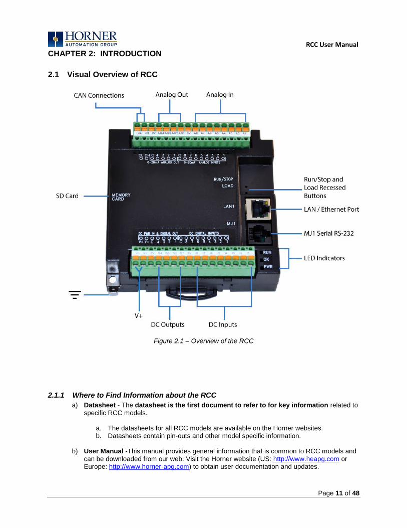
2.1 Visual Overview of RCC
Figure 2.1 – Overview of the RCC
2.1.1 Where to Find Information about the RCC
a) Datasheet - The datasheet is the first document to refer to for key information related to specific RCC models.
a. The datasheets for all RCC models are available on the Horner websites. b. Datasheets contain pin-outs and other model specific information.
b) User Manual -This manual provides general information that is common to RCC models and
can be downloaded from our web. Visit the Horner website (US: http://www.heapg.com or Europe: http://www.horner-apg.com) to obtain user documentation and updates.
RCC User Manual
Page 12 of 48
2.1.2 Four main types of information are covered in this manual
a) Safety and Installation guidelines / instructions (Mechanical and Electrical) b) Descriptions of hardware features
a. (Serial ports, Removable Media, Communication Options, etc.) c) Configuration and Use of the RCC d) Maintenance and Support
2.1.3 Manual Index
Major topics of interest may be found in the Index towards the end of this manual.
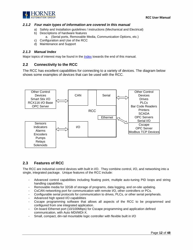
2.2 Connectivity to the RCC
The RCC has excellent capabilities for connecting to a variety of devices. The diagram below shows some examples of devices that can be used with the RCC.
2.3 Features of RCC
The RCC are industrial control devices with built in I/O. They combine control, I/O, and networking into a single, integrated package. Unique features of the RCC include:
- Advanced control capabilities including floating point, multiple auto-tuning PID loops and string handling capabilities.
- Removable media for 32GB of storage of programs, data logging, and on-site updating. - CsCAN networking port for communication with remote I/O, other controllers or PCs. - Configurable serial protocols for communication to drives, PLCs, or other serial peripherals. - Advanced high speed I/O capabilities - Cscape programming software that allows all aspects of the RCC to be programmed and
configured from one integrated application. - On board Ethernet port (10/100Mbps) for Cscape programming and application defined
communication, with Auto MDI/MDI-X. - Small, compact, din-rail mountable logic controller with flexible built in I/O
CAN
Serial
I/O
RCC
Other Control Devices Drives PLCs
Bar Code Readers Printers SCADA
OPC Servers Serial I/O
Sensors Indicators
Alarms Encoders
Pumps Relays
Solenoids
Other Control Devices
Smart Stix I/O RCX116 I/O Base
OPC Server
Ethernet
Cscape OPC Server
Modbus TCP Devices

RCC User Manual
Page 13 of 48
2.4 Required and Suggested Accessories
The following list contains a sampling of required and suggested RCC accessories. Visit the Horner websites to view updates on new products and accessories.
Table 2.1 – RCC Accessories
Part Number Description
HECSP Cscape Software Package on a reusable USB flash drive with symbol library.
HE-XCK Programming cables, including a USB to serial adapter in a travel case.
HE-CPK Cscape on a reusable USB flash drive.
Programming cables, including a USB to serial adapter in a travel case.
2.5 Useful Documents and References
The following information serves as a general listing of Horner controller products and other references of interest with their corresponding manual numbers. Visit the Horner websites to obtain user documentation and updates.
Table 2.2 – CONTROLLER Reference Document numbers
NOTE: This list is not intended for users to determine which products are appropriate for their application; controller products differ in the features that they support. If assistance is required, refer to Technical Support.
Manual Description Manual Number
Datasheet for RCC model MAN970
User Manual for XLe/XLt OCS models MAN0878
User Manual for RCC/RCCe OCS models MAN0883
User Manual for XL4 OCS models MAN0964
User Manual for QX Series models MAN0798
User Manual for NX Series models MAN0781
User Manual for XL7 OCS models MAN0974
User Manual for ZX OCS Models MAN1018
Other Useful References Manual Number
CAN Networks MAN0799
Spark Quenchers for Arc and Noise Suppression (output protection) MAN0962
Wiring Accessories and Spare Parts Manual MAN0347
Ethernet Communications SUP0740
NOTE: The RCC is not shipped with a programming cable in the box. To obtain a programming
cable, order HE500CBL300.
RCC User Manual
Page 14 of 48
CHAPTER 3: MECHANICAL INSTALLATION
Note: The datasheet is the first document to refer to for information related to RCC models such as pin-outs, I/O and general specification, and other key installation information. Visit the Horner websites to obtain datasheets, user documentation, and updates.
3.1 Overview
The mechanical installation greatly affects the operation, safety, and appearance of the system. Information is provided to mechanically install the unit such as cut-out sizes, mounting procedures and other recommendations for the proper mechanical installation of the unit.
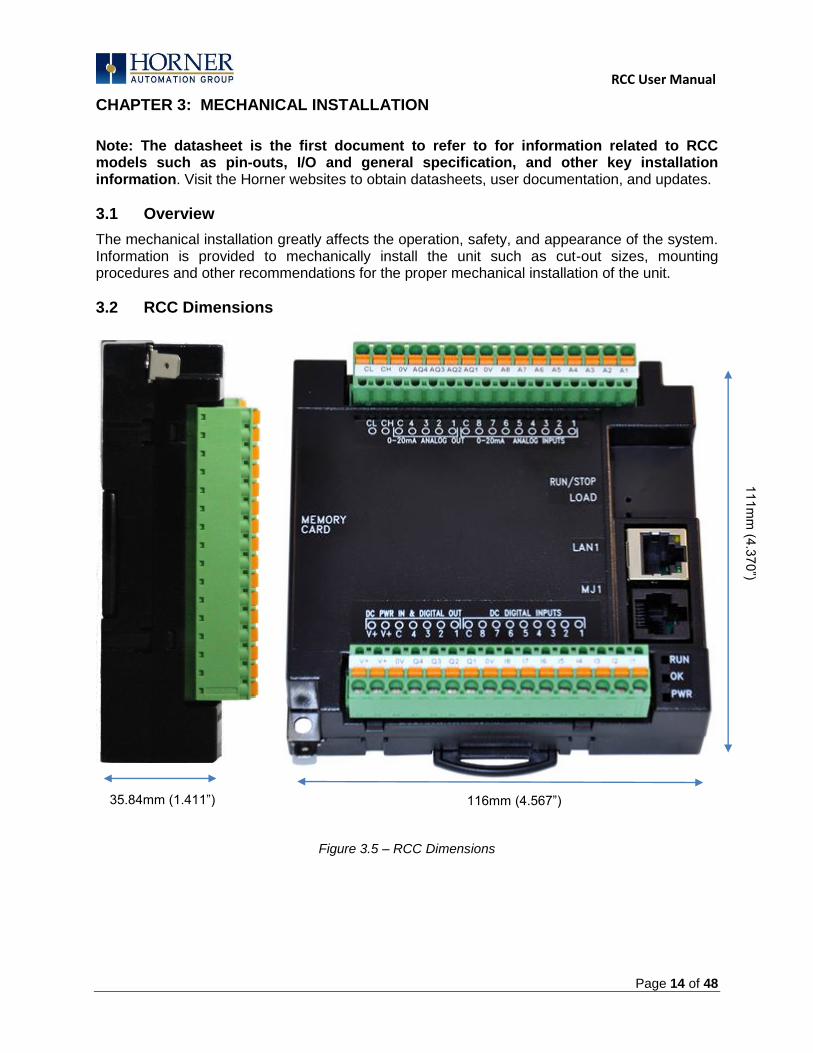
3.2 RCC Dimensions
Figure 3.5 – RCC Dimensions
35.84mm (1.411”) 116mm (4.567”)
111m
m (4
.370”)

RCC User Manual
Page 15 of 48
3.6.3 Temperature / Ventilation
Ensure that the DIN Rail layout design allows for adequate ventilation and maintains the specified ambient temperature range. Consider the impact on the design if operating at the extreme ends of the ambient temperature range. For example, if it is determined that a cooling device is required, allow adequate space and clearances for the device in the panel box or on the panel door if DIN rail is mounted inside.
3.6.4 Orientation
RCC should be mounted with locking DIN Tab facing down.
3.6.5 Noise
Consider the impact on the panel layout design and clearance requirements if noise suppression devices are needed. Be sure to maintain an adequate distance between the RCC and noisy devices such as relays, motor starters, etc. For details on output protection, especially when using contactors, solenoids see MAN0962-01-EN.
3.6.6 Shock and Vibration
The RCC has been designed to operate in typical industrial environments that may inflict some shock and vibration on the unit. For applications that may inflict excessive shock and vibration please use proper dampening techniques or relocate the RCC to a location that minimizes shock and/or vibration.

RCC User Manual
Page 16 of 48
CHAPTER 4: ELECTRICAL INSTALLATION
Note: The datasheet is the first document to refer to for model-specific information related to RCC models such as pin-outs and other key installation information. Visit the Horner websites to obtain datasheets, user documentation, and updates.
4.1 Grounding Definition
Ground: The term ground is defined as a conductive connection between a circuit or piece of equipment and the earth. Grounds are fundamentally used to protect an application from harmful interference causing either physical damage such as by lightning or voltage transients or from circuit disruption often caused by radio frequency interference (RFI). Grounding is also for the safety of the user.
4.2 Ground Specifications
Ideally, a ground resistance measurement from equipment to earth ground is 0 ohms. In reality it typically is higher. The U.S. National Electrical Code (NEC) states the resistance to ground shall not exceed twenty-five (25) ohms. Horner APG recommends less than fifteen (15) ohms resistance from our equipment to ground. Resistance greater than twenty-five (25) ohms can cause undesirable or harmful interference to the device.
4.3 How to Test for Good Ground
In order to test ground resistance, a Ground Resistance Tester must be used. A typical Ground Resistance Meter Kit contains a meter, two or three wire leads, and two ground rods. Instructions are supplied for either a two-point or three-point ground test.
Figure 4.1 – Two-Point Ground Connection Test
METAL WATER PIPE OROTHER GOOD GROUND
GROUND ROD
GROUNDDISCONNECTEDFROM SERVICE
GROUND RESISTANCE METER
RCC User Manual
Page 17 of 48
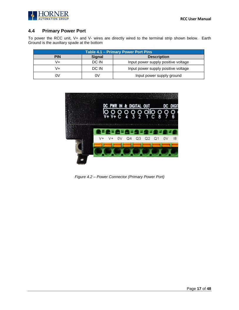
4.4 Primary Power Port
To power the RCC unit, V+ and V- wires are directly wired to the terminal strip shown below. Earth Ground is the auxiliary spade at the bottom
Table 4.1 – Primary Power Port Pins
PIN Signal Description
V+ DC IN Input power supply positive voltage
V+ DC IN Input power supply positive voltage
0V 0V Input power supply ground
Figure 4.2 – Power Connector (Primary Power Port)
RCC User Manual
Page 18 of 48
CHAPTER 5: SERIAL COMMUNICATIONS
5.1 Overview
All RCC models provide one serial port, on the first 8-pin modular RJ45 connector, which is labeled MJ1. The MJ1 serial port is RS232. By default, MJ1 can be connected to the COM port of a PC running Cscape, for controller programming. In addition, MJ1 can be used for application-specific communication, using a variety of standard data exchange protocols.
5.2 Port Descriptions
The MJ1 serial port contains an RS232 interface with RTS/CTS handshaking.
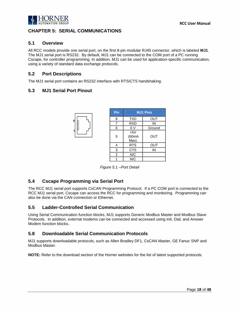
5.3 MJ1 Serial Port Pinout
Figure 5.1 –Port Detail
5.4 Cscape Programming via Serial Port
The RCC MJ1 serial port supports CsCAN Programming Protocol. If a PC COM port is connected to the RCC MJ1 serial port, Cscape can access the RCC for programming and monitoring. Programming can also be done via the CAN connection or Ethernet.
5.5 Ladder-Controlled Serial Communication
Using Serial Communication function blocks, MJ1 supports Generic Modbus Master and Modbus Slave Protocols. In addition, external modems can be connected and accessed using Init, Dial, and Answer Modem function blocks.
5.8 Downloadable Serial Communication Protocols
MJ1 supports downloadable protocols, such as Allen Bradley DF1, CsCAN Master, GE Fanuc SNP and Modbus Master.
NOTE: Refer to the download section of the Horner websites for the list of latest supported protocols.
Pin MJ1 Pins
8 TXD OUT
7 RXD IN
6 0 V Ground
5 +5V
(60mA Max)
OUT
4 RTS OUT
3 CTS IN
2 N/C
1 N/C
8
1
RCC User Manual
Page 19 of 48
CHAPTER 6: CAN COMMUNICATIONS
Note: For additional CAN information, refer to the CAN Networks manual (MAN0799) on the Horner websites.
6.1 Overview
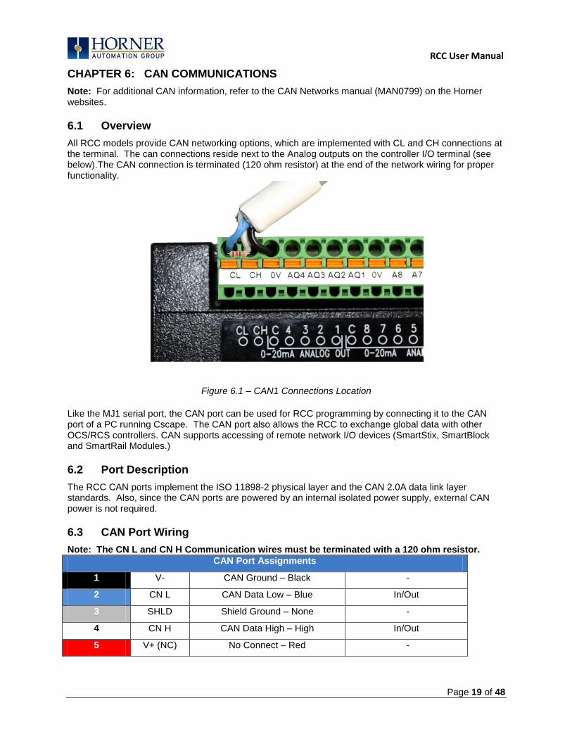
All RCC models provide CAN networking options, which are implemented with CL and CH connections at the terminal. The can connections reside next to the Analog outputs on the controller I/O terminal (see below).The CAN connection is terminated (120 ohm resistor) at the end of the network wiring for proper functionality.
Figure 6.1 – CAN1 Connections Location
Like the MJ1 serial port, the CAN port can be used for RCC programming by connecting it to the CAN port of a PC running Cscape. The CAN port also allows the RCC to exchange global data with other OCS/RCS controllers. CAN supports accessing of remote network I/O devices (SmartStix, SmartBlock and SmartRail Modules.)
6.2 Port Description
The RCC CAN ports implement the ISO 11898-2 physical layer and the CAN 2.0A data link layer standards. Also, since the CAN ports are powered by an internal isolated power supply, external CAN power is not required.
6.3 CAN Port Wiring
Note: The CN L and CN H Communication wires must be terminated with a 120 ohm resistor.
CAN Port Assignments
1 V- CAN Ground – Black -
2 CN L CAN Data Low – Blue In/Out
3 SHLD Shield Ground – None -
4 CN H CAN Data High – High In/Out
5 V+ (NC) No Connect – Red -
RCC User Manual
Page 20 of 48
6.4 Cscape Programming via CAN
The CAN port supports CsCAN Programming Protocol. If a PC has a CAN interface installed (via PCI card or USB), and the PC CAN port is connected to the RCC CAN port, Cscape can access the RCC for programming and monitoring.
In addition, the RCC supports single-point-programming of all RCC and other OCS/RCS devices that are connected to the CAN port network. If the PC COM port is connected to the RCC MJ1 serial port, the RCC can act as a pass-through gateway allowing Cscape to access all RCC and OCS/RCS devices that are attached to the CAN port network.
6.5 Ladder-Controlled CAN Communication
Using Put and Get Network Words function blocks, the CAN port can exchange digital and analog global data with other RCC or OCS/RCS devices (nodes) attached to the CAN port network.
In addition, Put and Get Network Heartbeat function blocks allow nodes on the CAN port network to regularly announce their presence and to detect the presence (or absence) of other nodes on the network.
6.6 Using CAN for I/O Expansion (Network I/O)
Connecting Network I/O devices (SmartStix, SmartBlock or SmartRail) to the RCC CAN port, allows the RCC I/O to be economically expanded and distributed. A variety of modules are available for this purpose.
RCC User Manual
Page 21 of 48
CHAPTER 7: ETHERNET COMMUNICATION
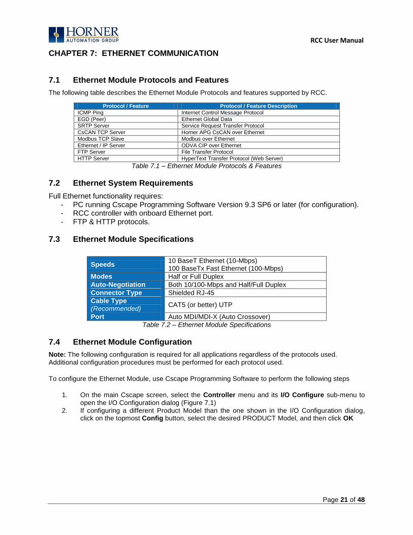
7.1 Ethernet Module Protocols and Features
The following table describes the Ethernet Module Protocols and features supported by RCC.
Protocol / Feature Protocol / Feature Description
ICMP Ping Internet Control Message Protocol
EGD (Peer) Ethernet Global Data
SRTP Server Service Request Transfer Protocol
CsCAN TCP Server Horner APG CsCAN over Ethernet
Modbus TCP Slave Modbus over Ethernet
Ethernet / IP Server ODVA CIP over Ethernet
FTP Server File Transfer Protocol
HTTP Server HyperText Transfer Protocol (Web Server)
Table 7.1 – Ethernet Module Protocols & Features
7.2 Ethernet System Requirements
Full Ethernet functionality requires: - PC running Cscape Programming Software Version 9.3 SP6 or later (for configuration). - RCC controller with onboard Ethernet port. - FTP & HTTP protocols.
7.3 Ethernet Module Specifications
Speeds 10 BaseT Ethernet (10-Mbps) 100 BaseTx Fast Ethernet (100-Mbps)
Modes Half or Full Duplex
Auto-Negotiation Both 10/100-Mbps and Half/Full Duplex
Connector Type Shielded RJ-45
Cable Type (Recommended)
CAT5 (or better) UTP
Port Auto MDI/MDI-X (Auto Crossover)
Table 7.2 – Ethernet Module Specifications
7.4 Ethernet Module Configuration
Note: The following configuration is required for all applications regardless of the protocols used. Additional configuration procedures must be performed for each protocol used.
To configure the Ethernet Module, use Cscape Programming Software to perform the following steps
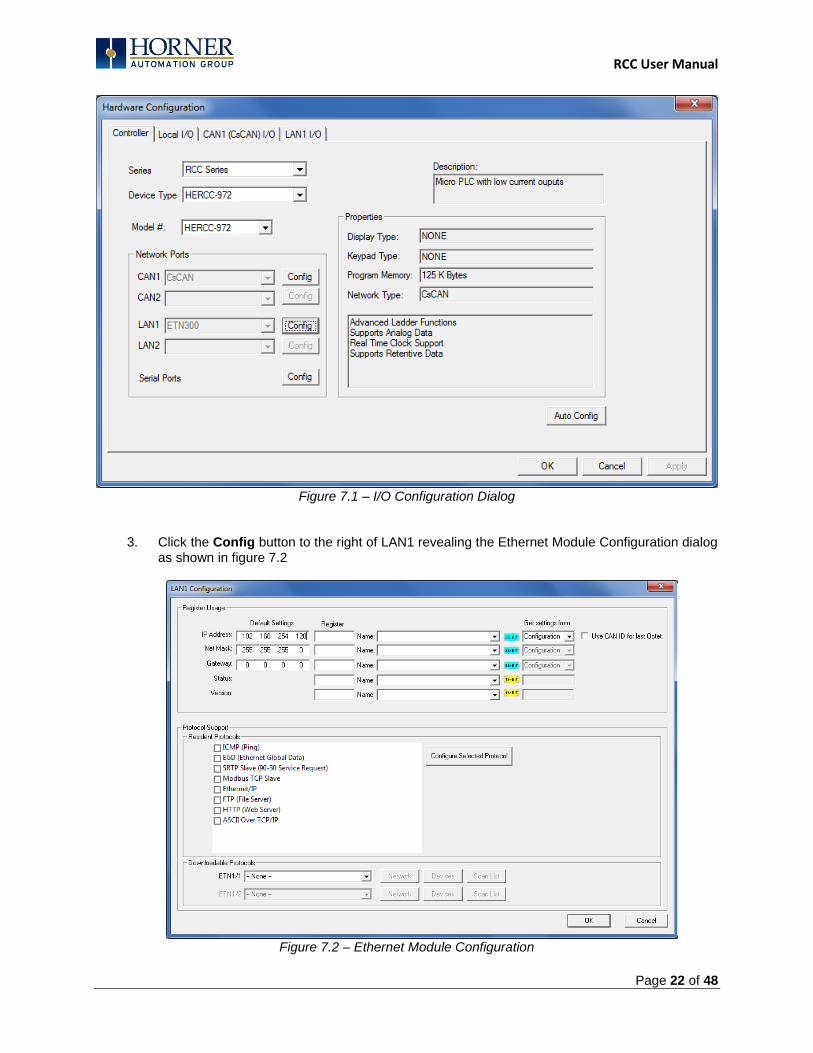
1. On the main Cscape screen, select the Controller menu and its I/O Configure sub-menu to
open the I/O Configuration dialog (Figure 7.1) 2. If configuring a different Product Model than the one shown in the I/O Configuration dialog,
click on the topmost Config button, select the desired PRODUCT Model, and then click OK
RCC User Manual
Page 22 of 48
Figure 7.1 – I/O Configuration Dialog
3. Click the Config button to the right of LAN1 revealing the Ethernet Module Configuration dialog as shown in figure 7.2
Figure 7.2 – Ethernet Module Configuration

RCC User Manual
Page 23 of 48
4. Configure the Ethernet Module parameters as follows: IP Address: Enter the static IP Address for the Ethernet Module being configured.
Note: IP Addresses are entered as four numbers, each ranging from 0 to 255. These four numbers are called octets and they are always separated by decimal points.
Net Mask: Enter the Net Mask (sometimes called Subnet Mask) being used by all nodes on the local network. Typical local networks use Class C IP Addresses, in which case the low octet (rightmost number) is used to uniquely identify each node on the local network. In this case, the default Net Mask value of 255.255.255.0 should be used. Gateway: Enter the IP Address of a Gateway Server on the local network that allows for communication outside of the local network. To prevent the Ethernet Module from communicating outside the local network, set the Default Gateway IP Address to 0.0.0.0 (the default setting). Status Register: Enter an Register reference (such as %R100) to indicate which 16-bit register will have the Ethernet Status word written to it. Table 7.3 shows how this register value is formatted and explains the meaning of each bit in the Status Word.
Table 7.3 - Ethernet Status Word Register Format
High Byte Low Byte
Bit 16
Bit 15
Bit 14
Bit 13
Bit 12
Bit 11
Bit 10
Bit 9
Bit 8
Bit 7
Bit 6
Bit 5
Bit 4
Bit 3
Bit 2
Bit 1
0 0 Dup Spd 0 Rx Tx Link TCP Connections
Status Bit(s) Status Indication Status Values
Minimum Maximum
0 Reserved Always 0
Dup Link Duplex (Auto-Negotiated) 0 = Half Duplex 1 = Full Duplex
Spd Link Speed (Auto-Negotiated) 0 = 10 MHz 1 = 100 MHz
Rx Receive State 0 = Inactive 1 = Active
Tx Transmit State 0 = Inactive 1 = Active
Link Link State 0 = Down 1 = Up
TCP Connections Total Number of Active TCP Connections
(CsCAN, SRTP, Modbus, EIP, FTP, HTTP) 0 40
Version Register: Enter a Register reference (such as %R101) to indicate which 16-bit register will have the Ethernet Firmware Version written to it. The value stored in the Version Register is: (Ethernet Firmware Version * 100). For example, for Ethernet Firmware Version 4.30, the Version register will contain 430.
Get Settings From: “Get settings from” allows the programmer to either configure the IP Address, Net Mask, or Gateway for 2 functions: Configuration or Register Configuration – The configuration for the IP Address, Net Mask, or the Gateway will be assigned using the value in the Default Settings in this window.
Register – The configuration for the IP Address, Net Mask, or the Gateway will be assigned using the values in the registers assigned.

RCC User Manual
Page 24 of 48
Ethernet Module Protocol Configuration The Protocol Support area contains a list of all the protocols supported by the platform being configured. To activate a protocol, check its checkbox. For protocols that require additional configuration, click on a listed protocol to select it and then click the Configure Selected Protocol button. This will open a new dialog with configuration options for the selected protocol. For detailed information on individual protocol configuration refer latest version of ETN 300 Manual SUP0740

RCC User Manual
Page 25 of 48
NOTES

RCC User Manual
Page 26 of 48
CHAPTER 8: REMOVABLE MEDIA
8.1 Overview
All RCC models provide a Removable Media slot, labeled Memory Card, which supports standard MicroSD Flash memory cards. MicroSD cards can be used to save and load applications, to capture graphics screens and to log data for later retrieval.
Figure 8.1 – Removable MicroSD Memory Card Slot
8.2 MicroSD Cards
Cards labeled either MicroSD or TransFlash, with up to 32 GB of Flash memory, are compatible with the RCC Memory slot (larger sizes were not tested at time of publication).
The Memory slot is equipped with a “push-in, push-out” connector and a MicroSD card can be safely inserted into the Memory slot whether the RCC power is On or Off.
To install a MicroSD card: Align its 8-pin gold edge connector down, facing the front of the RCC unit as shown in Figure 9.2; then carefully push it all the way into the Memory slot. Ensure that it clicks into place. To remove the MicroSD card: Push in on the top of the card gently to release the spring. The card pops out for removal.
8.3 MicroSD File System
The MicroSD Memory slot uses the PC-compatible FAT32 File System. This means that a PC, with a MicroSD-compatible card reader, can read files that have been written by the RCC and can write files that can be read by the RCC. However, the RCC does not support long filenames, but instead implements the 8.3 filename format. This means that all file and directory names must consist of up to 8 characters, followed by an optional dot, and an optional extension with up to 3 characters. Directories and sub-directories can be nested up to 16 levels deep as long as each pathname string does not exceed 147 characters.
RCC User Manual
Page 27 of 48
8.5 Using Removable Media to Log Data
Using Read and Write Removable Media function blocks, an application ladder program can read and write RCC register data in the form of comma-delimited files, with a .CSV extension. These files are compatible with standard database and spreadsheet PC programs. In addition, an application ladder program can use Rename and Delete Removable Media function blocks to rename and delete files.
8.6 Using Removable Media to Load and Save Applications
A special file type, with a .PGM extension, is used to store RCC application programs on MicroSD. Pressing and holding the LOAD button for three seconds upon power up will load the program that is stored on the MicroSD. (more details in Chapter 11) Cscape can also save an application directly to a MicroSD card, which is plugged into the PC‟s MicroSD compatible card reader by selecting the Export to Removable Media item on the Cscape File menu.
8.8 Removable Media (RM) Function Blocks in Cscape
NOTE: For detailed information regarding RM function blocks and parameters, refer to the help file in Cscape Software.
The following RM functional blocks are available in Cscape Software. These function blocks will reference
- MicroSD when filename is prefixed with „A:‟ or nothing
Read RM csv Allows reading of a comma-separated value file from the MicroSD interface into
the controller register space.
Write RM csv Allows writing of a comma-separated value file to the MicroSD interface from the controller register space.
Rename RM csv Allows renaming a file on the RM card. The data in the file is not changed.
Delete RM csv Allows deleting a file on the RM card
Copy RM csv Allows copying a file on the RM card. The data in the file is not changed.
8.9 Filenames used with the Removable Media (RM) Function Blocks
The RM function blocks support the flash with a DOS/Windows standard FAT-16 file system. All names must be limited to the “8.3” format where the filename contains eight characters a period then a three-character extension. The entire filename including any path must be less than or equal to 147 characters.
When creating filenames and directories it is sometimes desirable to include parts of the current date or time. There are six special symbols that can be entered into a filename that are replaced by the RCC with current time and date information.
Table 9.1 – Filename Special Symbols
Symbol Description Example
$Y Substitutes the current 2 digit year 2014 = 14
$M Substitutes the current month with a 2 digit code March = 03
$D Substitutes the current day 22nd
= 22
$h Substitutes the current hour in 24 hour format 4 pm = 16
$m Substitutes the current minute 45 = 45
$s Substitutes the current second 34 = 34
Note that all the symbols start with the dollar sign ($) character. Date symbols are in upper case, time symbols are in lower case. The following are examples of the substituted time/date filenames:
RCC User Manual
Page 28 of 48
Current date and time = March 1, 2013 3:45:34 PM Filename: Data$M$D.csv = Data0301.csv Filename: Year$Y\Month$M\aa$D_$h.csv = Year04\Month03\aa01_15.csv Filename: Month_$M\Day_$D\$h_$m_$s.csv = Month_03\Day_01\15_45_34.csv
Note: Time/Date requires setting on the RCC972, and is only maintained while the RCC is powered. Time and Date will need to be reconfigured on power cycle.
8.10 System Registers used with RM
%SR175 Status This shows the current status of the RM interface
%SR176 Free Space This 32-bit register shows the free space on the RM card in bytes
%SR178 Card Capacity This 32-bit register shows the total card capacity in kilobytes
Possible status values are shown in the table:
For additional status information, consult the Cscape help file.
Table 9.2 – RM Status Values
0 RM interface OK
1 Card present but unknown format
2 No card in slot
3 Card present, but not supported
4 Card swapped before operation was complete
5 Unknown error
RCC User Manual
Page 29 of 48
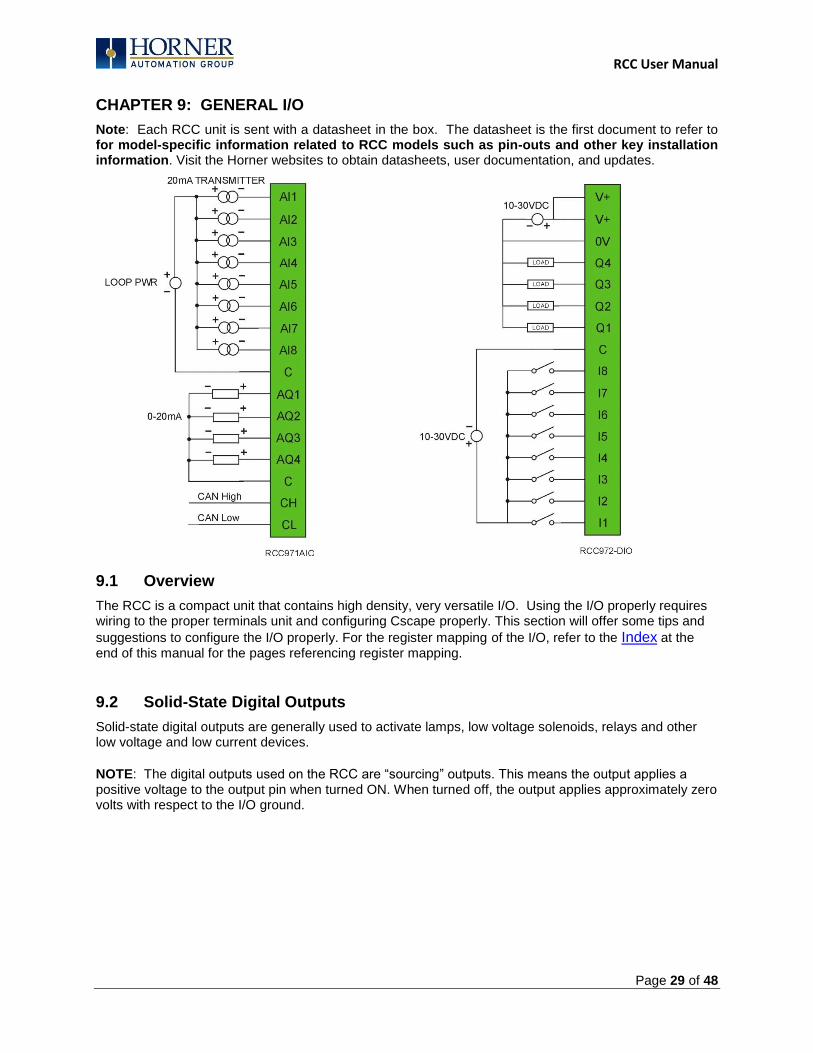
CHAPTER 9: GENERAL I/O
Note: Each RCC unit is sent with a datasheet in the box. The datasheet is the first document to refer to for model-specific information related to RCC models such as pin-outs and other key installation information. Visit the Horner websites to obtain datasheets, user documentation, and updates.
9.1 Overview
The RCC is a compact unit that contains high density, very versatile I/O. Using the I/O properly requires wiring to the proper terminals unit and configuring Cscape properly. This section will offer some tips and
suggestions to configure the I/O properly. For the register mapping of the I/O, refer to the Index at the end of this manual for the pages referencing register mapping.
9.2 Solid-State Digital Outputs
Solid-state digital outputs are generally used to activate lamps, low voltage solenoids, relays and other low voltage and low current devices.
NOTE: The digital outputs used on the RCC are “sourcing” outputs. This means the output applies a positive voltage to the output pin when turned ON. When turned off, the output applies approximately zero volts with respect to the I/O ground.
RCC User Manual
Page 30 of 48
The digital outputs used in the RCC have electronic short circuit protection and current limiting. While these electronic protections work in most applications, some application may require external fusing on these outputs. The digital outputs in the RCC are typically controlled via %Q bits in the register mapping. When the controller is stopped the operation of each output is configurable. The outputs can hold the state they were in before the controller stopped or they can go to a predetermined state. By default digital outputs turn off. For more information on stop state see the Index to find pages referencing Cscape settings.
The digital outputs feature an output fault bit. %I32 will turn on if any of the outputs experience a short circuit, over-current or the output driver overheats.
9.3 Digital Inputs
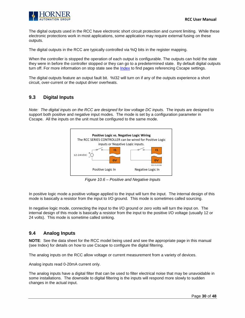
Note: The digital inputs on the RCC are designed for low voltage DC inputs. The inputs are designed to support both positive and negative input modes. The mode is set by a configuration parameter in Cscape. All the inputs on the unit must be configured to the same mode.
Figure 10.6 – Positive and Negative Inputs
In positive logic mode a positive voltage applied to the input will turn the input. The internal design of this mode is basically a resistor from the input to I/O ground. This mode is sometimes called sourcing.
In negative logic mode, connecting the input to the I/O ground or zero volts will turn the input on. The internal design of this mode is basically a resistor from the input to the positive I/O voltage (usually 12 or 24 volts). This mode is sometime called sinking.
9.4 Analog Inputs
NOTE: See the data sheet for the RCC model being used and see the appropriate page in this manual (see Index) for details on how to use Cscape to configure the digital filtering.
The analog inputs on the RCC allow voltage or current measurement from a variety of devices. Analog inputs read 0-20mA current only. The analog inputs have a digital filter that can be used to filter electrical noise that may be unavoidable in some installations. The downside to digital filtering is the inputs will respond more slowly to sudden changes in the actual input.
I1
0V
001XLE036
12-24VDC
I1
0V
Positive Logic In Negative Logic In
Positive Logic vs. Negative Logic Wiring The RCC SERIES CONTROLLER can be wired for Positive Logic
inputs or Negative Logic inputs.

RCC User Manual
Page 31 of 48
9.4.1 Common cause of analog input tranzorb failure.
If a 4-20mA circuit is initially wired with loop power but without a load, the analog input could see 24Vdc. This is higher than the rating of the tranzorb.
This can be solved by not connecting loop power prior to load connection or by installing a low-cost PTC in series between the load and the analog input.
Figure 10.7 – Analog input tranzorb - troubleshooting
9.5 Analog Outputs
Note: Refer to the datasheet for RCC model being used for details on jumper settings. The analog outputs on RCC devices provide 0-20mA current output. When the controller is stopped the operation of each output is configurable. The outputs can hold the state they were in before the controller stopped or they can go to a predetermined value. By default analog outputs are set to a value of zero. For more information on Stop State, refer to the appropriate
pages (see Index) for the configuration chapter for Cscape settings.

RCC User Manual
Page 32 of 48
CHAPTER 10: CSCAPE CONFIGURATION
10.1 Overview
RCC hardware is programmed with a Windows based PC application called Cscape. This application can be used to program, configure, monitor and debug all aspects of the RCC unit. Please see the on-line help provided with Cscape for additional details.
10.2 Cscape Status Bar
When the RCC is connected to a PC using Cscape software a Status Bar appears at the bottom of the screen. The Cscape Status Bar can be used to determine if communications have been established between the RCC and the Cscape program. Components of the Cscape Status Bar are explained below.
Ready User: HE-XExx1-CsCAN (Model=)
Equal Local :1 Target :2(R) [no forces]
MOD
Figure 10.1 - Cscape Status Bar
Equal Indicator – indicates whether the current program in Cscape is equal to the program stored in the Target Controller.
If Equal, the program in Cscape is the same as the program stored in the Target Controller.
If Not Equal, the program in Cscape is not the same as the program stored in the Target Controller.
If Unknown, there may have been a change since the last time the program in Cscape was compared to the Target Controller.
Communications Status - indicates the current status of the “pass through” Connector.
Local: xx – indicates the Network ID of the CONTROLLER to which the Cscape program is physically connected through its serial port. It can serve as a pass through device to other nodes on the network.
Target: yy(R) – indicates the Network ID of the device with which the Cscape program is exchanging data.
Note: The Local unit and Target unit can be the same unit or they can be separate units.
The following are status indicators: (R) – Running (D) - Do I/o (I) – Idle (?) – Cscape is not communicating with the remote unit. [no forces] – indicates no I/O has been forced.
Message Line - The contents of these messages are context sensitive. The Message line can be empty.
Current User - indicates who is logged (for security purposes).
Controller Model - Network (Model Confirmation)
Controller Model indicates the controller model for which the program in Cscape is configured.
Network indicates the type of network that the program in Cscape expects to use (e.g., CsCAN).
(Model Confirmation) provides the following indications:
(Model=) - the actual Target Controller matches the configured Controller Model and Network.
(Model Not=) – the actual Target Controller does not match the configured Controller Model and Network.
(Model ?) – there may have been a change since the last time the Target Controller was compared to the configured Controller Model and Network.
File Modified Indicator - indicates that the file in the selected window has
been modified but has not been saved.
RCC User Manual
Page 33 of 48
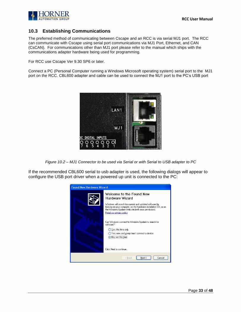
10.3 Establishing Communications
The preferred method of communicating between Cscape and an RCC is via serial MJ1 port. The RCC can communicate with Cscape using serial port communications via MJ1 Port, Ethernet, and CAN (CsCAN). For communications other than MJ1 port please refer to the manual which ships with the communications adapter hardware being used for programming.
For RCC use Cscape Ver 9.30 SP6 or later.
Connect a PC (Personal Computer running a Windows Microsoft operating system) serial port to the MJ1 port on the RCC. CBL600 adapter and cable can be used to connect the MJ1 port to the PC‟s USB port
Figure 10.2 – MJ1 Connector to be used via Serial or with Serial to USB adapter to PC
If the recommended CBL600 serial to usb adapter is used, the following dialogs will appear to configure the USB port driver when a powered up unit is connected to the PC:
RCC User Manual
Page 34 of 48
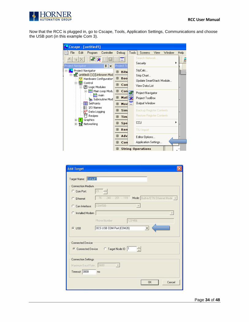
Now that the RCC is plugged in, go to Cscape, Tools, Application Settings, Communications and choose the USB port (in this example Com 3).

RCC User Manual
Page 35 of 48
If communication is established, the target indicator will show the mode of the controller Target: yy(R) as shown in the status section above in this chapter, section Cscape Status Bar. If the controller is not communicating, ensure the target ID is set correctly. The Target ID allows directing communications to a particular unit when multiple units are connected via a CsCAN network. Units without CsCAN network ports respond to any network ID and do not require the ID to be configured. To change the RCC target ID in Cscape, go to ControllerSet Local Network ID.
10.3.1 Communicating via MJ1 Serial Port
Start by configuring Cscape to use the correct communications port. This can be done using the ToolsOptionsCommunication Port dialog in Cscape. Connect the PC‟s serial port to the port labeled MJ1 on the RCC.
If communications are successful, the target indicator should show the mode of the controller Target: yy(R) as shown in the status section above.
If the controller is not communicating, it may be required to set the target ID of the controller in Cscape The Target ID allows directing communications to a particular unit when multiple units are connected via a CsCAN network. Units without CsCAN network ports respond to any network ID and do not require the ID to be configured.
To change the Target ID of Cscape use the ControllerSet Target Network ID dialog.
10.3.2 Communicating via On Board Ethernet Port
From Cscape go to Controller -> I/O Configure and do auto configuration for the connected controller, Click on Config of Ethernet & go to Module Setup.
The IP address, Net Mask and Gateway of the controller may be temporarily set from the system menu under the Set Networks menu item. Once running or power cycled the configuration will come from the Cscape configuration stored in the unit.
In Module configuration dialog go to IP Address field enter unused IP Address and configure unused registers in Register field & then click OK. Screen shot for the same as follows:
RCC User Manual
Page 36 of 48
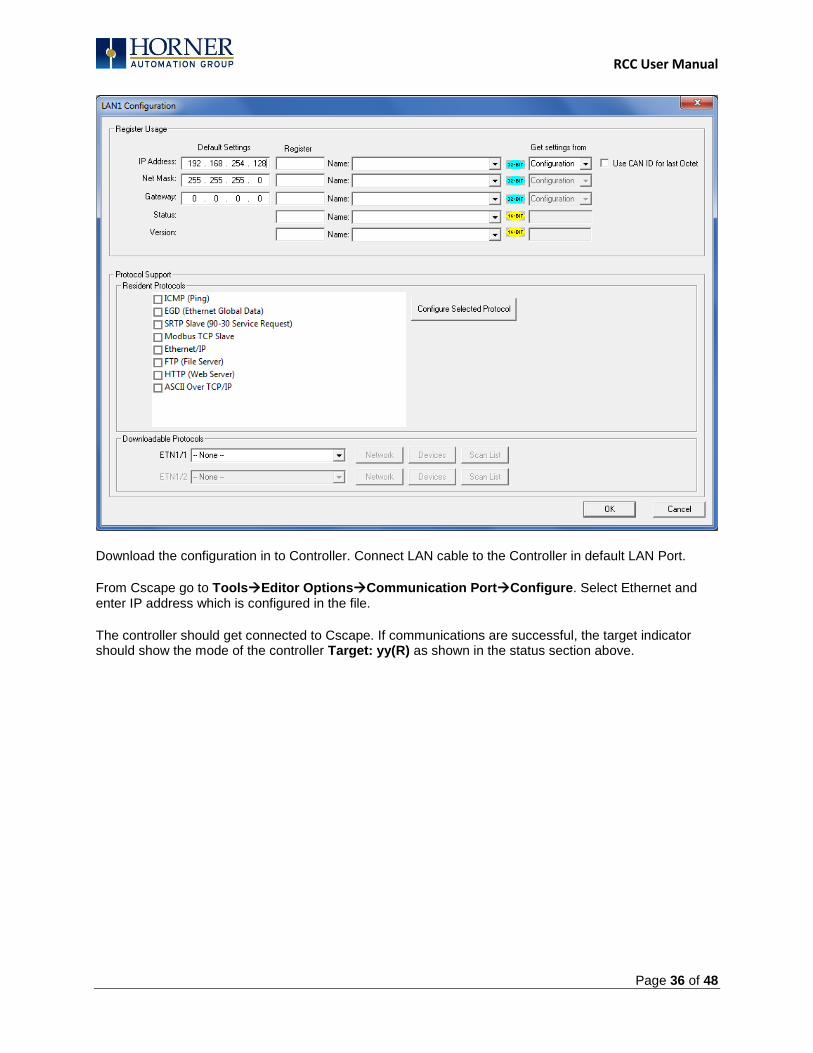
Download the configuration in to Controller. Connect LAN cable to the Controller in default LAN Port.
From Cscape go to ToolsEditor OptionsCommunication PortConfigure. Select Ethernet and enter IP address which is configured in the file.
The controller should get connected to Cscape. If communications are successful, the target indicator should show the mode of the controller Target: yy(R) as shown in the status section above.
RCC User Manual
Page 37 of 48
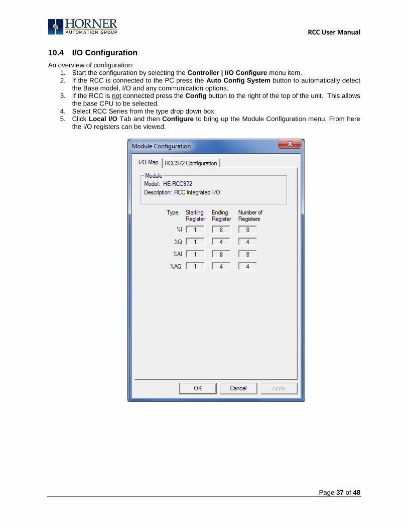
10.4 I/O Configuration
An overview of configuration: 1. Start the configuration by selecting the Controller | I/O Configure menu item. 2. If the RCC is connected to the PC press the Auto Config System button to automatically detect
the Base model, I/O and any communication options. 3. If the RCC is not connected press the Config button to the right of the top of the unit. This allows
the base CPU to be selected. 4. Select RCC Series from the type drop down box. 5. Click Local I/O Tab and then Configure to bring up the Module Configuration menu. From here
the I/O registers can be viewed.
RCC User Manual
Page 38 of 48
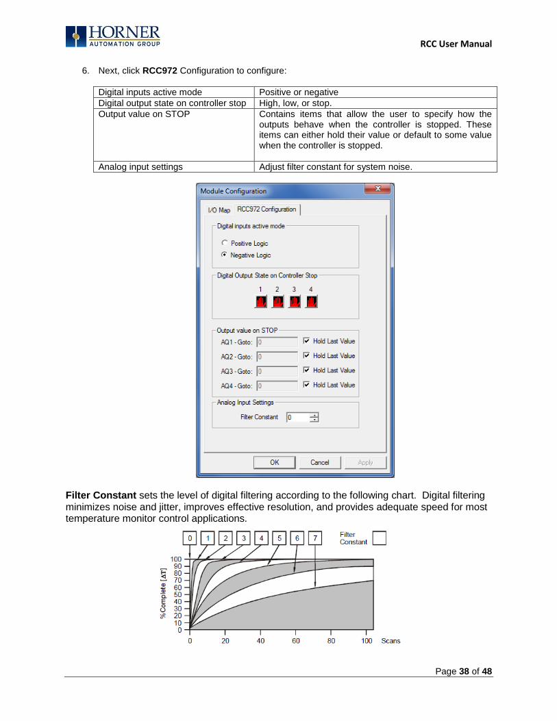
6. Next, click RCC972 Configuration to configure:
Digital inputs active mode Positive or negative
Digital output state on controller stop High, low, or stop.
Output value on STOP Contains items that allow the user to specify how the outputs behave when the controller is stopped. These items can either hold their value or default to some value when the controller is stopped.
Analog input settings Adjust filter constant for system noise.
Filter Constant sets the level of digital filtering according to the following chart. Digital filtering minimizes noise and jitter, improves effective resolution, and provides adequate speed for most temperature monitor control applications.
RCC User Manual
Page 39 of 48
CHAPTER 11: REGISTERS
11.1 Register Definitions
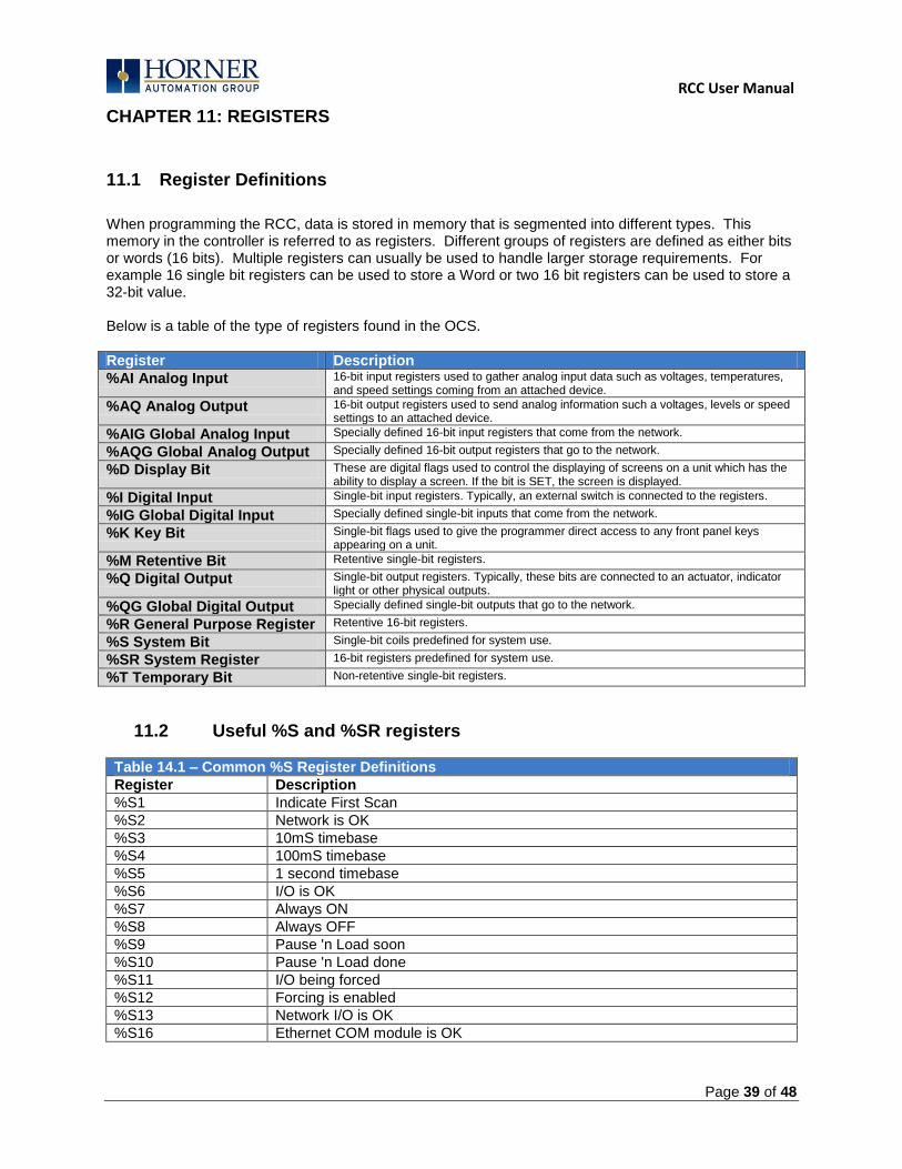
When programming the RCC, data is stored in memory that is segmented into different types. This memory in the controller is referred to as registers. Different groups of registers are defined as either bits or words (16 bits). Multiple registers can usually be used to handle larger storage requirements. For example 16 single bit registers can be used to store a Word or two 16 bit registers can be used to store a 32-bit value. Below is a table of the type of registers found in the OCS.
Register Description
%AI Analog Input 16-bit input registers used to gather analog input data such as voltages, temperatures, and speed settings coming from an attached device.
%AQ Analog Output 16-bit output registers used to send analog information such a voltages, levels or speed settings to an attached device.
%AIG Global Analog Input Specially defined 16-bit input registers that come from the network.
%AQG Global Analog Output Specially defined 16-bit output registers that go to the network.
%D Display Bit These are digital flags used to control the displaying of screens on a unit which has the ability to display a screen. If the bit is SET, the screen is displayed.
%I Digital Input Single-bit input registers. Typically, an external switch is connected to the registers.
%IG Global Digital Input Specially defined single-bit inputs that come from the network.
%K Key Bit Single-bit flags used to give the programmer direct access to any front panel keys appearing on a unit.
%M Retentive Bit Retentive single-bit registers.
%Q Digital Output Single-bit output registers. Typically, these bits are connected to an actuator, indicator light or other physical outputs.
%QG Global Digital Output Specially defined single-bit outputs that go to the network.
%R General Purpose Register Retentive 16-bit registers.
%S System Bit Single-bit coils predefined for system use.
%SR System Register 16-bit registers predefined for system use.
%T Temporary Bit Non-retentive single-bit registers.
11.2 Useful %S and %SR registers
Table 14.1 – Common %S Register Definitions
Register Description
%S1 Indicate First Scan
%S2 Network is OK
%S3 10mS timebase
%S4 100mS timebase
%S5 1 second timebase
%S6 I/O is OK
%S7 Always ON
%S8 Always OFF
%S9 Pause 'n Load soon
%S10 Pause 'n Load done
%S11 I/O being forced
%S12 Forcing is enabled
%S13 Network I/O is OK
%S16 Ethernet COM module is OK
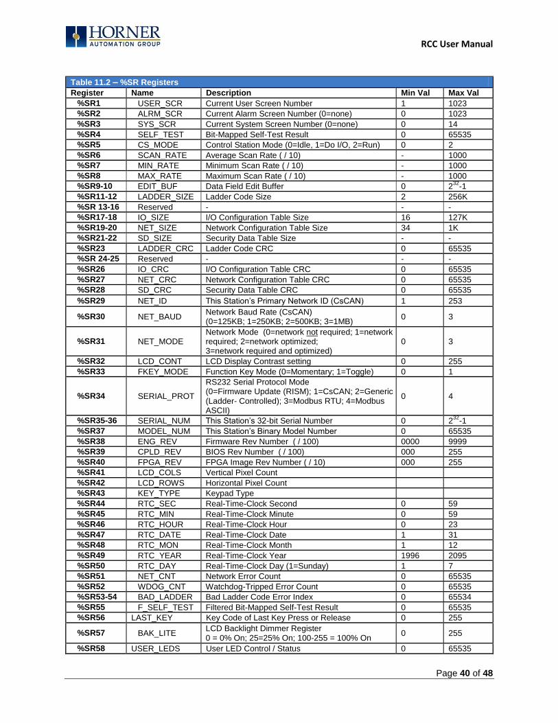
RCC User Manual
Page 40 of 48
Table 11.2 – %SR Registers
Register Name Description Min Val Max Val
%SR1 USER_SCR Current User Screen Number 1 1023
%SR2 ALRM_SCR Current Alarm Screen Number (0=none) 0 1023
%SR3 SYS_SCR Current System Screen Number (0=none) 0 14
%SR4 SELF_TEST Bit-Mapped Self-Test Result 0 65535
%SR5 CS_MODE Control Station Mode (0=Idle, 1=Do I/O, 2=Run) 0 2
%SR6 SCAN_RATE Average Scan Rate ( / 10) - 1000
%SR7 MIN_RATE Minimum Scan Rate ( / 10) - 1000
%SR8 MAX_RATE Maximum Scan Rate ( / 10) - 1000
%SR9-10 EDIT_BUF Data Field Edit Buffer 0 232
-1
%SR11-12 LADDER_SIZE Ladder Code Size 2 256K
%SR 13-16 Reserved - - -
%SR17-18 IO_SIZE I/O Configuration Table Size 16 127K
%SR19-20 NET_SIZE Network Configuration Table Size 34 1K
%SR21-22 SD_SIZE Security Data Table Size - -
%SR23 LADDER_CRC Ladder Code CRC 0 65535
%SR 24-25 Reserved - - -
%SR26 IO_CRC I/O Configuration Table CRC 0 65535
%SR27 NET_CRC Network Configuration Table CRC 0 65535
%SR28 SD_CRC Security Data Table CRC 0 65535
%SR29 NET_ID This Station‟s Primary Network ID (CsCAN) 1 253
%SR30 NET_BAUD Network Baud Rate (CsCAN) (0=125KB; 1=250KB; 2=500KB; 3=1MB)
0 3
%SR31 NET_MODE Network Mode (0=network not required; 1=network required; 2=network optimized; 3=network required and optimized)
0 3
%SR32 LCD_CONT LCD Display Contrast setting 0 255
%SR33 FKEY_MODE Function Key Mode (0=Momentary; 1=Toggle) 0 1
%SR34 SERIAL_PROT
RS232 Serial Protocol Mode (0=Firmware Update (RISM); 1=CsCAN; 2=Generic (Ladder- Controlled); 3=Modbus RTU; 4=Modbus ASCII)
0 4
%SR35-36 SERIAL_NUM This Station‟s 32-bit Serial Number 0 232
-1
%SR37 MODEL_NUM This Station‟s Binary Model Number 0 65535
%SR38 ENG_REV Firmware Rev Number ( / 100) 0000 9999
%SR39 CPLD_REV BIOS Rev Number ( / 100) 000 255
%SR40 FPGA_REV FPGA Image Rev Number ( / 10) 000 255
%SR41 LCD_COLS Vertical Pixel Count
%SR42 LCD_ROWS Horizontal Pixel Count
%SR43 KEY_TYPE Keypad Type
%SR44 RTC_SEC Real-Time-Clock Second 0 59
%SR45 RTC_MIN Real-Time-Clock Minute 0 59
%SR46 RTC_HOUR Real-Time-Clock Hour 0 23
%SR47 RTC_DATE Real-Time-Clock Date 1 31
%SR48 RTC_MON Real-Time-Clock Month 1 12
%SR49 RTC_YEAR Real-Time-Clock Year 1996 2095
%SR50 RTC_DAY Real-Time-Clock Day (1=Sunday) 1 7
%SR51 NET_CNT Network Error Count 0 65535
%SR52 WDOG_CNT Watchdog-Tripped Error Count 0 65535
%SR53-54 BAD_LADDER Bad Ladder Code Error Index 0 65534
%SR55 F_SELF_TEST Filtered Bit-Mapped Self-Test Result 0 65535
%SR56 LAST_KEY Key Code of Last Key Press or Release 0 255
%SR57 BAK_LITE LCD Backlight Dimmer Register 0 = 0% On; 25=25% On; 100-255 = 100% On
0 255
%SR58 USER_LEDS User LED Control / Status 0 65535
RCC User Manual
Page 41 of 48
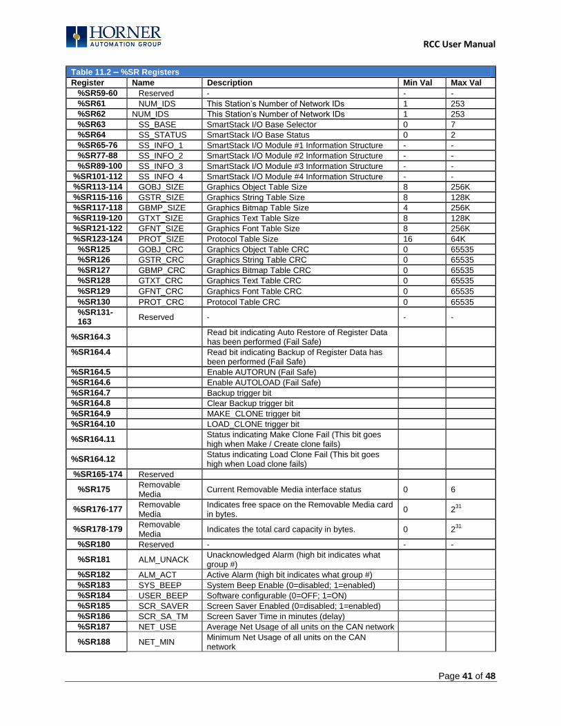
Table 11.2 – %SR Registers
Register Name Description Min Val Max Val
%SR59-60 Reserved - - -
%SR61 NUM_IDS This Station‟s Number of Network IDs 1 253
%SR62 NUM_IDS This Station‟s Number of Network IDs 1 253
%SR63 SS_BASE SmartStack I/O Base Selector 0 7
%SR64 SS_STATUS SmartStack I/O Base Status 0 2
%SR65-76 SS_INFO_1 SmartStack I/O Module #1 Information Structure - -
%SR77-88 SS_INFO_2 SmartStack I/O Module #2 Information Structure - -
%SR89-100 SS_INFO_3 SmartStack I/O Module #3 Information Structure - -
%SR101-112 SS_INFO_4 SmartStack I/O Module #4 Information Structure - -
%SR113-114 GOBJ_SIZE Graphics Object Table Size 8 256K
%SR115-116 GSTR_SIZE Graphics String Table Size 8 128K
%SR117-118 GBMP_SIZE Graphics Bitmap Table Size 4 256K
%SR119-120 GTXT_SIZE Graphics Text Table Size 8 128K
%SR121-122 GFNT_SIZE Graphics Font Table Size 8 256K
%SR123-124 PROT_SIZE Protocol Table Size 16 64K
%SR125 GOBJ_CRC Graphics Object Table CRC 0 65535
%SR126 GSTR_CRC Graphics String Table CRC 0 65535
%SR127 GBMP_CRC Graphics Bitmap Table CRC 0 65535
%SR128 GTXT_CRC Graphics Text Table CRC 0 65535
%SR129 GFNT_CRC Graphics Font Table CRC 0 65535
%SR130 PROT_CRC Protocol Table CRC 0 65535
%SR131-163
Reserved - - -
%SR164.3 Read bit indicating Auto Restore of Register Data has been performed (Fail Safe)
%SR164.4
Read bit indicating Backup of Register Data has been performed (Fail Safe)
%SR164.5 Enable AUTORUN (Fail Safe)
%SR164.6 Enable AUTOLOAD (Fail Safe)
%SR164.7 Backup trigger bit
%SR164.8 Clear Backup trigger bit
%SR164.9 MAKE_CLONE trigger bit
%SR164.10 LOAD_CLONE trigger bit
%SR164.11 Status indicating Make Clone Fail (This bit goes high when Make / Create clone fails)
%SR164.12 Status indicating Load Clone Fail (This bit goes high when Load clone fails)
%SR165-174 Reserved
%SR175 Removable Media
Current Removable Media interface status 0 6
%SR176-177 Removable Media
Indicates free space on the Removable Media card in bytes.
0 231
%SR178-179 Removable Media
Indicates the total card capacity in bytes. 0 231
%SR180 Reserved - - -
%SR181 ALM_UNACK Unacknowledged Alarm (high bit indicates what group #)
%SR182 ALM_ACT Active Alarm (high bit indicates what group #)
%SR183 SYS_BEEP System Beep Enable (0=disabled; 1=enabled)
%SR184 USER_BEEP Software configurable (0=OFF; 1=ON)
%SR185 SCR_SAVER Screen Saver Enabled (0=disabled; 1=enabled)
%SR186 SCR_SA_TM Screen Saver Time in minutes (delay)
%SR187 NET_USE Average Net Usage of all units on the CAN network
%SR188 NET_MIN Minimum Net Usage of all units on the CAN network
RCC User Manual
Page 42 of 48
Table 11.2 – %SR Registers
Register Name Description Min Val Max Val
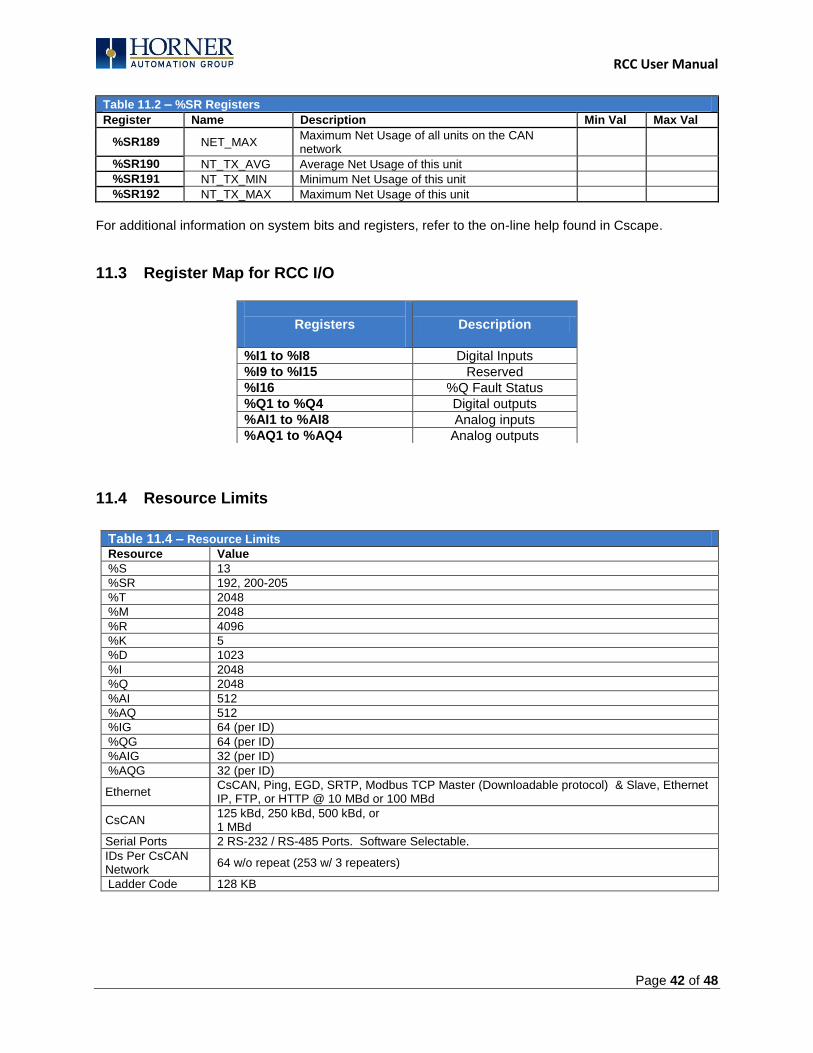
%SR189 NET_MAX Maximum Net Usage of all units on the CAN network
%SR190 NT_TX_AVG Average Net Usage of this unit
%SR191 NT_TX_MIN Minimum Net Usage of this unit
%SR192 NT_TX_MAX Maximum Net Usage of this unit
For additional information on system bits and registers, refer to the on-line help found in Cscape.
11.3 Register Map for RCC I/O
11.4 Resource Limits
Table 11.4 – Resource Limits
Resource Value
%S 13
%SR 192, 200-205
%T 2048
%M 2048
%R 4096
%K 5
%D 1023
%I 2048
%Q 2048
%AI 512
%AQ 512
%IG 64 (per ID)
%QG 64 (per ID)
%AIG 32 (per ID)
%AQG 32 (per ID)
Ethernet CsCAN, Ping, EGD, SRTP, Modbus TCP Master (Downloadable protocol) & Slave, Ethernet IP, FTP, or HTTP @ 10 MBd or 100 MBd
CsCAN 125 kBd, 250 kBd, 500 kBd, or 1 MBd
Serial Ports 2 RS-232 / RS-485 Ports. Software Selectable.
IDs Per CsCAN Network
64 w/o repeat (253 w/ 3 repeaters)
Ladder Code 128 KB
Registers
Description
%I1 to %I8 Digital Inputs
%I9 to %I15 Reserved
%I16 %Q Fault Status
%Q1 to %Q4 Digital outputs
%AI1 to %AI8 Analog inputs
%AQ1 to %AQ4 Analog outputs

RCC User Manual
Page 43 of 48
CHAPTER 12: MAINTENANCE
12.1 Firmware Updates
The RCC products contain field updatable firmware to allow new features to be added to the product at a later time. Firmware updates should only be performed when a new feature or correction is required.
Load switch
1. Pressing the LOAD switch during power-up boots from the Micro SD card. This starts a Firmware Load if the Micro SD is bootable and valid firmware files are found on it.
2. After boot-up, pressing the LOAD switch for 3 seconds either starts a Firmware Load or an Application Load depending upon what files are found on the Micro SD. If firmware files are found, a Firmware Load is performed. If firmware files are not found and the DEFAULT.PGM file is found, an Application Load is performed.
CHAPTER 13: TROUBLESHOOTING / TECHNICAL SUPPORT
Chapter 13 provides commonly requested troubleshooting information and checklists for the following topics.
- Connecting to the RCC controller - Local controller and local I/O - CsCAN Network - Removable media
In the event that this information is not enough, please contact Technical Support at the locations indicated at the end of this chapter. LED - NORMAL FUNCTIONALITY
LED Off ON Flash (1Hz)
PWR No power applied
10-30Vdc applied
OK Self test fail Self test pass I/O forcing enabled.
RUN Stop mode Run Mode Do I/O Mode.
Switch - Normal Functionality
Load switch - Used for firmware updated, as noted in previous section
Run/Stop switch 1. After boot-up, pressing the RUN/STOP switch for 3 seconds toggles the RCC between RUN and STOP
modes.
Switch – Erase Program Function
LOAD and RUN/STOP 1. After boot-up, pressing both Load and RUN/Stop switches for 3 seconds performs an “Erase All” function,
which deletes all application programs.
Warning: Firmware updates should only be performed when the equipment being controlled by the RCC is in a safe, non-operational state. Communication or hardware failures during the firmware update process can cause the controller to behave erratically resulting in injury or equipment damage. Make sure the functions of the equipment work properly after a firmware update before returning the device to an operational mode.
LED Load Program/Firmware Functionality
LED OK & RUN
Flashing Alternately
Flashing Together
Flashing Stops
Load program or firmwre
Download in Progress
Download fails, number of flashes indicates the error.
Download Complete, unit reboots (allow 30
seconds).
RCC User Manual
Page 44 of 48
LED – Diagnostic Functionality
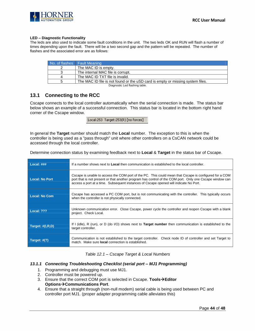
The leds are also used to indicate some fault conditions in the unit. The two leds OK and RUN will flash a number of times depending upon the fault. There will be a two second gap and the pattern will be repeated. The number of flashes and the associated error are as follows:
No. of flashes Fault Meaning
2 The MAC ID is empty.
3 The internal MAC file is corrupt.
4 The MAC ID TXT file is invalid.
5 The MAC ID file is not found or the uSD card is empty or missing system files. Diagnostic Led flashing table.
13.1 Connecting to the RCC
Cscape connects to the local controller automatically when the serial connection is made. The status bar below shows an example of a successful connection. This status bar is located in the bottom right hand corner of the Cscape window.
In general the Target number should match the Local number. The exception to this is when the controller is being used as a "pass through" unit where other controllers on a CsCAN network could be accessed through the local controller. Determine connection status by examining feedback next to Local & Target in the status bar of Cscape.
Local: ### If a number shows next to Local then communication is established to the local controller.
Local: No Port Cscape is unable to access the COM port of the PC. This could mean that Cscape is configured for a COM port that is not present or that another program has control of the COM port. Only one Cscape window can access a port at a time. Subsequent instances of Cscape opened will indicate No Port.
Local: No Com Cscape has accessed a PC COM port, but is not communicating with the controller. This typically occurs when the controller is not physically connected.
Local: ??? Unknown communication error. Close Cscape, power cycle the controller and reopen Cscape with a blank project. Check Local.
Target: #(I,R,D) If I (idle), R (run), or D (do I/O) shows next to Target number then communication is established to the target controller.
Target: #(?) Communication is not established to the target controller. Check node ID of controller and set Target to match. Make sure local connection is established.
Table 12.1 – Cscape Target & Local Numbers
13.1.1 Connecting Troubleshooting Checklist (serial port – MJ1 Programming)
1. Programming and debugging must use MJ1. 2. Controller must be powered up. 3. Ensure that the correct COM port is selected in Cscape. ToolsEditor
OptionsCommunications Port. 4. Ensure that a straight through (non-null modem) serial cable is being used between PC and
controller port MJ1. (proper adapter programming cable alleviates this)

RCC User Manual
Page 45 of 48
5. Check that a Loaded Protocol or ladder is not actively using MJ1. Using the STOP recessed button on the controller will make MJ1 available to Cscape.
6. Make sure the COM port of the PC is functioning. An RS232 serial loopback and Microsoft HyperTerminal can determine positively if the COM port is working. Or connect to an alternate device to determine if the port is working.
7. Successful communications with USB-to-serial adapters vary. If in doubt, Horner APG offers a USB to serial adapter. Part number HE500USB600.
13.1.2 Connecting Troubleshooting Checklist (ETN port programming)
1. Programming and debugging must use MJ1 or Ethernet Port. 2. Controller must be powered up. 3. Ensure that correct IP address is given in the Ethernet field and correct Mode is selected, in
Cscape: ToolsEditor OptionsCommunications Port 4. Ensure that the Ethernet Cable is connected between the controller and the Ethernet Hub.
5. Make sure the Ethernet cable is functioning properly.
13.2 Local Controller and Local I/O
The system menu provides the following status indications that are useful for troubleshooting and system maintenance.
- Self-test results, diagnostics. - RUN and OK status - Network status and usage - Average logic scan rate - Application memory usage - Loaded firmware versions - Loaded protocols - Removable media access
13.3 CsCAN Network
For complete information on setting up a CsCAN network, refer to CAN Networks manual (MAN0799) by visiting the Horner websites for the address to obtain documentation and updates. Network status, node ID, errors, and baud rate in the controller system menu are all in reference to the CsCAN network. These indications can provide performance feedback on the CsCAN network and can also be used to aid in troubleshooting.
13.3.1 CsCAN Network Troubleshooting Checklist
1. Use the proper Belden wire type or equivalent for the network as specified in MAN0799. 2. The RCC does not provide 24VDC to the network. An external voltage source must be used for
other devices such as SmartStix I/O. 3. Check voltage at both ends of the network to insure that voltage meets specifications of
attached devices. 4. Proper termination is required. Use 121-ohm (or 120-ohm) resistors at each end of the
network. The resistors should be placed across the CAN_HI and CAN_LO terminals. 5. Measure the resistance between CAN_HI and CAN_LO. If the network is properly wired and
terminated there should be around 60 ohms. 6. Check for duplicate node ID‟s.
WARNING: Setting outputs ON in Do I/O mode can result in injury or cause machinery
to engage in an unsafe manner depending on the application and the environment.
RCC User Manual
Page 46 of 48
7. Keep proper wires together. One twisted pair is for V+ and V- and the other twisted pair is used for CAN_HI and CAN_LO.
8. Make sure the baud rate is the same for all controllers on the network. 9. Assure shields are connected at one end of each segment -- they are not continuous through
the network. 10. Do not exceed the maximum length determined by the baud rate and cable type. 11. Total drop length for each drop should not exceed 6m (20 feet). A drop may include more than
one node. The drop length adds to the overall network length. 12. Network should be wired in "straight line" fashion, not in a "star" pattern. 13. In applications requiring multiple power supplies, make sure the V- of all supplies is connected
together and to earth ground at one place only. 14. In some electrically noisy environments it may be necessary to add repeaters to the network.
Repeaters can be used to add additional nodes and/or distance to the network and protect the signal against noisy environments. The Horner APG repeater is part # HE200CGM100.\
13.4 Removable Media - Basic Troubleshooting
Description Action
RCC does not read media card. Attempt to reformat MicroSD card on PC
RCC will not download project file.
Make sure the project file is saved as a .pgm file and not a .csp file. In addition, to file must be .pgm, the file's I/O configuration must match the RCC configuration for it to download.
Table 19.2 – Removable Media Troubleshooting
13.5 Technical Support Contacts
For manual updates and assistance, contact Technical Support at the following locations: North America: Tel: 1-877-665-5666 Fax: (317) 639-4279 www.heapg.com Email: [email protected] Europe: Tel: (+) 353-21-4321-266 Fax: (+353)-21-4321826 www.horner-apg.com Email: [email protected]

RCC User Manual
Page 47 of 48
Main Index
%Q bits, 30 Accessories, 13 Analog Inputs, 30 Analog Outputs, 31 CAN Comm
Cscape Programming, 20 I/O Expansion (Network I/O), 20 Ladder-Controlled, 20 Overview, 19 Ports, 19
CAN Communications, 19 CE, 10 COM, 18, 20, 40, 45, 46 COM port, 34, 45, 46 Communicating via MJ1 Serial Port, 36 Communication options, 21 Communications Port, 34, 45, 46 Compliance
CE, 10 Csape Program
Via Serial Port, 18 Cscape, 12, 13, 18, 19, 20, 27, 29, 30, 31, 32, 33,
35, 36, 43, 45, 46 Configuration Procedures, 38 Establishing Communications, 33 Overview, 32 Status Bar, 32
CSCAPE CONFIGURATION, 32 datasheet, 7, 29, 30, 31 Default Gateway, 23 Devices to Connect to RCC, 12 Digital Inputs, 30 Dimensions, 14 ELECTRICAL INSTALLATION, 16 Ethernet, 33, 40 Ethernet Communication, 21 Ethernet Module
Default Gateway, 23 IP Address, 23 Net Mask, 23 Status Register, 23 Version Register, 23
Ethernet Module Configuration, 21 Ethernet Module Protocol Configuration, 24 Ethernet Module Protocols and Features, 21 Ethernet Module Specifications, 21 Ethernet System Requirements, 21
Features, 12 Firmware Updates, 44 Front Panel and USB Programming Connector, 33 fusing, 30 General I/O
Overview, 29 GENERAL I/O, 29 Ground Specification, 16 Grounding
Locations of Information, 10 Grounding Definition, 16 IP Address, 23 LIMITED WARRANTY, 3 Maintenance, 44 Manual Index, 12 MECHANICAL INSTALLATION, 14 Micro SD Cards, 26
Installing / Removing, 26 Micro SD System, 26 Net Mask, 23 OCS Reference Document Numbers, 13 Panel Box
Noise, 15 Orientation, 15 Temperature, 15
Panel Box Shock and Vibration, 15 Power Connector (Primary Power Port), 17 Primary Power Port, 17 Primary Power Port As Viewed Looking at the RCC
OCS, 17 Primary Power Port Pins, 17 PROGRAMMING EXAMPLES, 3 References / Useful documents, 13 register mapping, 29, 30 registers, 40 Registers
Definitions, 40 I/O, 43 Resource Limits, 43
Removable Media Load / Save Applications, 27 Log Data, 27 Overview, 26
REMOVABLE MEDIA, 26 Removable Memory Card Slot Photograph, 26 safety / compliance, 9 Safety Warnings, Guidelines, 9
RCC User Manual
Page 48 of 48
Serial Comm Cscape Programming, 18 Downloadable Protocols, 18 Ladder-Controlled, 18 Overview, 18 Ports, 18 Wiring, 18
SERIAL COMMUNICATIONS, 18 Solid-State Digital Outputs, 29 sourcing, 29, 30 stop state, 30 Table of Contents, 5 target ID, 36 Target ID, 36 target indicator, 35, 36, 37 Technical Support, 2, 13, 44, 47
Contacts, 47 Testing for Good Ground, 16 Troubleshooting
Common problems, 45 Connecting Checklist, 45 CsCAN Checklist, 46 CsCAN Network, 46 Local Controller / I/O, 46 Removable Media, 47
troubleshooting / technical support, 45 Troubleshooting Checklist (serial port – MJ1)
Programming, 45 Troubleshooting Checklist (Ethernet port
Programming) [For RCCe only], 46 Two-Point Ground Connection Test, 16 USB, 20, 33, 46 Visual Overview of RCC and Topics, 11 Where to Find Information, 11 RCC Dimensions, 14 RCC Manual PREFACE, 2 RCC OCS Accessories, 13 RCC OCS Dimensions, 14