Embed Size (px)
Citation preview

UNIVERSAL HOLDING CABINETSERVICE AND REPAIR MANUAL
BLODGETT OVEN COMPANYwww.blodgett.com
44 Lakeside Avenue, Burlington, Vermont 05401 USA Telephone (800) 331-5842, (802) 860-3700 Fax: (802)864-0183
PN 33954 Rev B (6/01)E 1998 --- G.S. Blodgett Corporation All rights reserved.
Duplication of the information in this manual is prohibited without the consent of the Blodgett Service Department.

TABLE OF CONTENTS
i
1. INTRODUCTIONDescription 1---1. . . . . . . . . . . . . . . . . . . . . . . . . . . . . . . . . . . . . . . . . . . . . . . . . . . . . . . . . . . . . . . . . . . . . .Specifications 1---2. . . . . . . . . . . . . . . . . . . . . . . . . . . . . . . . . . . . . . . . . . . . . . . . . . . . . . . . . . . . . . . . . . . .
2. OPERATIONControl Panel Descriptions 2---1. . . . . . . . . . . . . . . . . . . . . . . . . . . . . . . . . . . . . . . . . . . . . . . . . . . . . . . . .Operator Mode 2---2. . . . . . . . . . . . . . . . . . . . . . . . . . . . . . . . . . . . . . . . . . . . . . . . . . . . . . . . . . . . . . . . . . .Timer Operation 2---3. . . . . . . . . . . . . . . . . . . . . . . . . . . . . . . . . . . . . . . . . . . . . . . . . . . . . . . . . . . . . . . . . .Meal Selection 2---4. . . . . . . . . . . . . . . . . . . . . . . . . . . . . . . . . . . . . . . . . . . . . . . . . . . . . . . . . . . . . . . . . . .Clean Mode 2---5. . . . . . . . . . . . . . . . . . . . . . . . . . . . . . . . . . . . . . . . . . . . . . . . . . . . . . . . . . . . . . . . . . . . . .Slot On/Off 2---6. . . . . . . . . . . . . . . . . . . . . . . . . . . . . . . . . . . . . . . . . . . . . . . . . . . . . . . . . . . . . . . . . . . . . . .Displaying Slot Temperature Information 2---7. . . . . . . . . . . . . . . . . . . . . . . . . . . . . . . . . . . . . . . . . . . . .Operating Tips 2---8. . . . . . . . . . . . . . . . . . . . . . . . . . . . . . . . . . . . . . . . . . . . . . . . . . . . . . . . . . . . . . . . . . .Sequence of Operation 2---9. . . . . . . . . . . . . . . . . . . . . . . . . . . . . . . . . . . . . . . . . . . . . . . . . . . . . . . . . . . .
3. PROGRAMMING AND CALIBRATIONStore Manager Programming 3---1. . . . . . . . . . . . . . . . . . . . . . . . . . . . . . . . . . . . . . . . . . . . . . . . . . . . . .Product Selection for Each Slot 3---1. . . . . . . . . . . . . . . . . . . . . . . . . . . . . . . . . . . . . . . . . . . . . . . . .Entering and Editing Product Information 3---6. . . . . . . . . . . . . . . . . . . . . . . . . . . . . . . . . . . . . . . .More Product Prompt Time Feature 3---11. . . . . . . . . . . . . . . . . . . . . . . . . . . . . . . . . . . . . . . . . . . . .Changing the Display Time 3---12. . . . . . . . . . . . . . . . . . . . . . . . . . . . . . . . . . . . . . . . . . . . . . . . . . . . .Changing the Display Intensity 3---13. . . . . . . . . . . . . . . . . . . . . . . . . . . . . . . . . . . . . . . . . . . . . . . . . .
Service Programming and Calibration 3---14. . . . . . . . . . . . . . . . . . . . . . . . . . . . . . . . . . . . . . . . . . . . . . .To Access Service Programming 3---14. . . . . . . . . . . . . . . . . . . . . . . . . . . . . . . . . . . . . . . . . . . . . . . .Offset Calibration 3---15. . . . . . . . . . . . . . . . . . . . . . . . . . . . . . . . . . . . . . . . . . . . . . . . . . . . . . . . . . . . .Display Test Mode 3---15. . . . . . . . . . . . . . . . . . . . . . . . . . . . . . . . . . . . . . . . . . . . . . . . . . . . . . . . . . . .Timer Fast Test 3---15. . . . . . . . . . . . . . . . . . . . . . . . . . . . . . . . . . . . . . . . . . . . . . . . . . . . . . . . . . . . . . .Changing from _F to _C 3---19. . . . . . . . . . . . . . . . . . . . . . . . . . . . . . . . . . . . . . . . . . . . . . . . . . . . . .Programming Alarms 3---20. . . . . . . . . . . . . . . . . . . . . . . . . . . . . . . . . . . . . . . . . . . . . . . . . . . . . . . . . .
4. TROUBLESHOOTINGTroubleshooting Elements and Warning Alarms 4---1. . . . . . . . . . . . . . . . . . . . . . . . . . . . . . . . . . . . . .Troubleshooting Flow Diagrams 4---4. . . . . . . . . . . . . . . . . . . . . . . . . . . . . . . . . . . . . . . . . . . . . . . . . . . .Troubleshooting a Locked Out Slot 4---10. . . . . . . . . . . . . . . . . . . . . . . . . . . . . . . . . . . . . . . . . . . . . . . . .Troubleshooting Sensor Alarms 4---11. . . . . . . . . . . . . . . . . . . . . . . . . . . . . . . . . . . . . . . . . . . . . . . . . . . .Troubleshooting the Driver Board and Control 4---12. . . . . . . . . . . . . . . . . . . . . . . . . . . . . . . . . . . . . . . .

TABLE OF CONTENTS
ii
5. PARTS REPLACEMENTElement or Probe Assembly 5---1. . . . . . . . . . . . . . . . . . . . . . . . . . . . . . . . . . . . . . . . . . . . . . . . . . . . . . . .Cooling Blower 5---2. . . . . . . . . . . . . . . . . . . . . . . . . . . . . . . . . . . . . . . . . . . . . . . . . . . . . . . . . . . . . . . . . . .Bezel Assembly 5---3. . . . . . . . . . . . . . . . . . . . . . . . . . . . . . . . . . . . . . . . . . . . . . . . . . . . . . . . . . . . . . . . . .Membrane Switch 5---4. . . . . . . . . . . . . . . . . . . . . . . . . . . . . . . . . . . . . . . . . . . . . . . . . . . . . . . . . . . . . . . .LED Board 5---4. . . . . . . . . . . . . . . . . . . . . . . . . . . . . . . . . . . . . . . . . . . . . . . . . . . . . . . . . . . . . . . . . . . . . . .Driver Board 5---5. . . . . . . . . . . . . . . . . . . . . . . . . . . . . . . . . . . . . . . . . . . . . . . . . . . . . . . . . . . . . . . . . . . . .Temperature Probe 5---5. . . . . . . . . . . . . . . . . . . . . . . . . . . . . . . . . . . . . . . . . . . . . . . . . . . . . . . . . . . . . . .Mother Board 5---5. . . . . . . . . . . . . . . . . . . . . . . . . . . . . . . . . . . . . . . . . . . . . . . . . . . . . . . . . . . . . . . . . . . .Bezel Gasket 5---6. . . . . . . . . . . . . . . . . . . . . . . . . . . . . . . . . . . . . . . . . . . . . . . . . . . . . . . . . . . . . . . . . . . . .Chip Replacement 5---7. . . . . . . . . . . . . . . . . . . . . . . . . . . . . . . . . . . . . . . . . . . . . . . . . . . . . . . . . . . . . . . .
6. TECHNICAL APPENDIXSchematic 6---1. . . . . . . . . . . . . . . . . . . . . . . . . . . . . . . . . . . . . . . . . . . . . . . . . . . . . . . . . . . . . . . . . . . . . . .Wiring Diagram 6---2. . . . . . . . . . . . . . . . . . . . . . . . . . . . . . . . . . . . . . . . . . . . . . . . . . . . . . . . . . . . . . . . . . .Temperature Probe 6---3. . . . . . . . . . . . . . . . . . . . . . . . . . . . . . . . . . . . . . . . . . . . . . . . . . . . . . . . . . . . . . .

INTRODUCTIONCHAPTER 1

UHC
1---1
DESCRIPTION
The Blodgett Universal Holding Cabinet is a shortterm holding device designed to maintain thefreshness of a variety of food product. The UHCcontains four product slots which can be con-trolled independently. Control panels are locatedabove each slot on both the front and rear of thecabinet. All operatormode selections can bemadefrom either the front or rear display.
Power Switch --- controls power to the cabinet.
Product Slot --- holds up to three trays of productper slot.
Control Panel --- indicates the holding time andproduct selection for each tray position.
1/3 Size Product Tray --- designed for all grilledproducts (meat, eggs, chicken). This tray main-tains the product’s moisture.
1/2 Size Crumb Tray with Wire Rack --- designedfor fried products (crispy chicken, nuggets, fillet).The tray keeps the fried crumbs from droppingthrough the racks. It also allows moisture to es-cape leaving the outside of the product crispy.
Full SizeProduct Tray --- designed for breadprod-ucts (biscuits and muffins). This tray allows a smallamount of moisture to escape.
Each Universal Holding Cabinet is shipped withthe following:D Equipment manualD PM cardD Training videoD Quick-reference guideD Cleaning brush
Control Panel
Product Slot
Power Switch
Knockouts forDouble Stacking
FIGURE 1

INTRODUCTION
1---2
SPECIFICATIONS
OVEN CLEARANCES
The following clearancesmust be available for ser-vicing.D Cabinet body sides --- 22” (56 cm)D Cabinet body back --- 25” (64 cm)
ELECTRICAL SPECIFICATIONS
Electrical Specifications (per section)
KW Hz Volts Phase Amps
U.S. and Canadian installations
2.5/3.3 50/60 208/240 1 20
General Export installations
2.5/3.3 50/60 208/240 1 20
TABLE 1
Installationmust conformwith local codes, or in theabsence of local codes, with the National ElectricalCode, ANSI/NFPA 70---Latest Edition and/or Cana-dian Electrical Code CSA C22.2 as applicable.
Wiring diagrams are located inside the right sidepanel.
This appliance is equipped with a three-pronggrounding plug for your protection against shockhazard and must be plugged into a properlygrounded three-prong receptacle. DONOT cut orremove the grounding prong from this plug.
CONTROL SPECIFICATIONS
Operating Voltage 208 VAC +10/---15% or240 VAC+10/---15%50 or 60 Hz
Input Voltage 264 VAC maximum177 VAC minimum
Load Requirements(heaters)
400 watt maximum at240 VAC, resistive load,8 heaters per cabinet max.
System OperatingEnvironment
50-104_F (10-40_C) with400 ft/minute airflow overcircuit board assemblies
Required HandlingPrecautions
Circuits contain sensitiveelectronic components.DO NOT ship or storenear strong electrostatic,electromagnetic, magnet-ic or radioactive field.
CAUTION: Due to elec-trostatically sensitivecomponents. All techni-cians performing servicework must be grounded.Grounding may be ac-complished using agrounding strap or othersuitable means. Connectto another grounded un-powered piece of equip-ment. (ie. equipment oth-er than the one you arecurrently working on.)
TABLE 2

UHC
1---3
This page intentionally left blank.

OPERATIONCHAPTER 2

UHC
2---1
CONTROL PANEL DESCRIPTIONS
UHC Front Control Panel
UHC Rear Control Panel
1 1 12 2 25 4 3
1 1 12 2 2
FIGURE 1
FRONT CONTROL PANEL
1. TIMER KEYS --- start and stop the timer associ-ated with each tray position. The timer keysalso turn off audible alarms. There are threetimer keys on each front panel (left, center andright).
2. DISPLAYS --- show product selection and holdtime for each tray position. The displays alsoprovide programming information in the pro-gram mode. There are three displays on eachfront panel (left, center and right).
3. MENU KEY --- press to select meal transitions(breakfast to lunch), clean mode operationand to turn individual slots on or off. The menukey also provides access to the programmode.
4. TEMPERATURE/ENTER/PAGE KEY --- this keyhas three separate functions.
D Display slot temperature information
D Enter operational changes
D Select pageparameters in programmode.
5. UP and DOWN ARROW KEYS --- press to in-crease/decrease variables or change selec-tions.
REAR CONTROL PANEL
NOTE: The rear panels are used for operationalfunctions only. All programming must beperformed from the front panels.
1. TIMER KEYS --- start and stop the timer associ-ated with each tray position. The timer keysalso turn off audible alarms. There are threetimer keys on each front panel (left, center andright).
2. DISPLAYS --- show product selection and holdtime for each tray position. There are three dis-plays on each front panel (left, center andright).

OPERATION
2---2
OPERATOR MODE
The operator mode is the normal operating modeof the controller when all slots are at the propertemperature and no alarm conditions exist. Prod-uct information and hold time are displayed.
SLOT TEMPERATURE CONTROL
Each product selection has its own temperaturesetpoint and product hold time. All product timersrun independently.
The slot temperature is controlled by the tempera-ture setpoint of the left most product entry in eachslot as viewed from the front of the cabinet (sidewith the On/Off switch). Product selections thathave a hold temperature different than the leftmost
product selection will not be available for entry intothat slot’s configuration.
DISPLAY INFORMATION
In the operator mode the slot displays provide thefollowing information:
D The product selection for each tray location.D The hold time remaining (in minutes) for activetimers.
NOTE: An active timer alternately displays theproduct selection and the time remaining.Inactive timers display only product selec-tion.
SAUS
12.!.!.!.
.!.!.!.Use first timer(highest intensity)
Active timer(medium intensity)
Inactive timer(lowest intensity)
Running dots (decimal points)
FIGURE 2

UHC
2---3
TIMER OPERATION
NOTE: If more than one tray of product is timing,the tray with the least hold time remainingis indicated by the Use First display.
Starting a timer
1. Press the TIMER KEY above the desired trayposition to start the timer. The timer countsdown from a preset value and alternately dis-plays product selection and the hold time re-maining.
Stopping a timer
1. Press the TIMER KEY above the slot positionto turn off an active timer. The timer stops tim-ing. The display changes to the inactive status.
Timing out
1. The time out alarm alerts the operator that theproduct hold time has expired. When the hold
time remaining reaches zero an audible alarmsounds and the display reads ---00---.
NOTE: The audible alarm is indicated by amodulating tone. A continuous tonesignals a warning alarm.
All other active displays in the cabinet switch tothe lowest intensity level until the audible alarmis turned off.
2. Press the TIMERKEY to clear the timedout dis-play and silence the alarm.
If other timers in the cabinet have timed out,the audible alarm remains on until all timed outdisplays are cleared.
3. When all timers are cleared, active timers re-turn to normal status. The Use First status isswitched to the next timer with the least holdtime remaining.
SAUS.!.!.!.
45.!.!.!.
Press timer key to start a timer
SAUS.!.!.!.
Display alternately indicates hold time andproduct selection for active timers.
SAUS.!.!.!.
Press timer key to stop or silence a timer
Use First indication changes to the next active timer
---00--- .!.!.!.
FIGURE 3

OPERATION
2---4
MEAL SELECTION
Selecting breakfast and lunch
NOTE: The following example is for selectingbreakfast. The same procedure applies forselecting lunch.
1. Press the MENU KEY to change the productselection of the slot from breakfast to lunch. Alldisplays are highlighted.
2. Press the ENTER KEY to activate the mealselection. The displays switch to the inactivemode.
NOTE: If the enter key is not pressed withinfive seconds, the product selection re-turns to the breakfast meal selection.
Changing meal selections
Active slots with active timers will not change to thenew meal selection until the timer(s) are stoppedor time out and are reset. Active timers are stoppedby pressing the timer key.
If the product selection for themeal has a hold tem-perature different than the current meal, a high orlow temperature alarm is displayed to alert the op-erator that the hold temperature is being changed.Should the high or low temperature condition re-main for two or more minutes, an audible alarmsounds. (See page 4---1 of the Troubleshootingsection.) To silence the alarm press any timer key.This does not affect the timer operation unless thetimer key is pressed again. The display alternatelyindicates the product selection and the alarmmes-sage until the slot temperature is within the presetlimits.
If no keys are pressed, the alarm message auto-matically resets when the slot temperature iswithinthe preset limits.
NUGG
Press menu key to display inactivemeal selection
NUGG NUGGPress enter key to enter meal selectionand return to normal display mode
FIGURE 4

UHC
2---5
CLEAN MODE
The cleanmode changes the temperature setpointof all slots in the cabinet to 125_F (52_C).
To start the clean mode
1. Press the MENU KEY to scroll to the cleanmode message, CLN MODE.
2. Press the ENTER KEY to activate the cleanmode. All slots change to clean mode.
NOTE: If the enter key is not pressed within 5seconds the control returns to the pre-vious meal selection.
If the temperature is above 125_F (52_C), thedisplay alternately reads SLOT CLN MODE
andNOTSAFE YET. The display reads SAFE TOCLN when the slot is 125_F (52_C).
To exit clean mode
1. Press the MENU KEY to display CLN MODE.
2. Press the ENTER KEY to exit the clean modeand return to normal operation. The slot alter-nately displays SLOT TEMP LOW and the prod-uct selection until the temperature is within thenormal operating limits.
NOTE: If the enter key is not pressed within 5seconds the slot returns to the cleanmode.
Press menu key to scroll to cleanmode message
Press enter key to return to normaldisplay mode
CLN MODEPress enter key to start clean mode
CLN MODE
SAFE TO CLN
To exit clean mode press menu keyto display clean mode message
EXIT CLN MODE
FIGURE 5

OPERATION
2---6
SLOT ON/OFF
To turn slot off
1. Press the MENU KEY to scroll to the slot offmessage, TURN SLOT OFF.
2. Press the ENTER KEY to enter the selection.The display reads SLOT IS OFF.
NOTE: If the enter key is not pressed withinfive seconds the product selection re-turns to the operator mode.
To turn slot on
1. Press the MENU KEY to scroll to the slot onmessage, TURN SLOT ON.
2. Press the ENTER KEY to enter the selectionand return to the operator mode. The displayalternately reads SLOT TEMP LOW and theproduct selection until the temperature is with-in normal operating limits.
NOTE: If the enter key is not pressed withinfive seconds the slot returns to slot offstatus.
Press menu key to scroll to slot offmessage
Press enter key to turn slot on and returnto normal display mode
TURN SLOT OFFPress enter key to turn slot off
SLOT IS OFF
SLOT IS OFF
Press menu key to scroll to slot onmessage
TURN SLOT ON
FIGURE 6

UHC
2---7
DISPLAYING SLOT TEMPERATURE INFORMATION
1. Press the TEMPERATURE KEY to scroll the fol-lowing temperature information for each slot:
D Top plate actual temperatureD Bottom plate actual temperature
D Top plate setpoint temperatureD Bottom plate setpoint temperature2. The display automatically returns to operatormode if no key is pressed for five seconds.
Press temperature key to display topplate temperature
Press temperature key to turn return tonormal display mode
TOP TEMP 155
TOP TSET 155
BOT TEMP 155
BOT TSET 155
Press temperature key to displaybottom plate temperature
Press temperature key to display topplate setpoint temperature
Press temperature key to display bottomplate setpoint temperature
FIGURE 7

OPERATION
2---8
OPERATING TIPS
Correct heat and moisture levels are important tothe proper operation of the UHC. There are nodoors in the cabinet. The trays act as doors, there-fore it is important that theybe positioned correctly.The trays must be inserted to the stop line. Thestop line is clearlymarked on the handle of all threetray styles.
Product Slots
The UHC has four slots that can hold up to threetrays of product per slot.
Slot 1
Slot 2
Slot 3
Slot 4
FIGURE 8
Fried Products
The 1/2 crumb tray with the wire rack is designedto hold all fried products.
D Product should be held in the wire rack whichis placed in the crumb tray.
D UHC tray liners are not necessary when usingthe wire rack for fried product.
Baked Products
The full size tray is designed to hold all bakedprod-ucts such as biscuits and muffins.D Use a UHC tray liner with the full size tray.D After biscuits have been removed from the bis-cuit oven, remove the wrapper and open thecardboard box. Slide the biscuits onto the trayliner.
D Full size trays can hold up to 30 frozen biscuits,20 scratch biscuits or 20 muffins.
Grilled Products
The 1/3 tray is designed to hold all grilled products.D Product should not be drainedwhenpickedupfrom the grill.
D Use a UHC tray liner with the 1/3 tray.D Product should be stacked when placed in thelined 1/3 size tray. 10:1 and sausage pattiescan be stacked up to six high. Eggs (exceptscrambled), grilled chicken and 4:1 patties canbe stacked up to three high.
D Product should be placed towards the centerof the tray.
FIGURE 9
Production control charts
Laminated charts can be ordered through O’BrienBudd, Inc. The ordering numbers are:D Breakfast UHC card #MCD 63102D Regular Menu UHC card # MDC 63102A

UHC
2---9
SEQUENCE OF OPERATION
COMPONENT REFERENCE
NOTE: Refer to FIGURE 10page2---10 for compo-nent locations.
1. METAL OXIDE VARISTOR2. DPST POWER SWITCH3. TANGENTIAL BLOWER4. TRANSFORMER 200-240V5. HEATER TRIAC6. HEATER ELEMENTS7. SHELF PROBES8. SHELF 1 DRIVER BOARD9. SHELF 2 DRIVER BOARD10. SHELF 3 DRIVER BOARD11. SHELF 4 DRIVER BOARD12. SHELF 1 FRONT DISPLAY ASSY.13. SHELF 2 FRONT DISPLAY ASSY.14. SHELF 3 FRONT DISPLAY ASSY.15. SHELF 4 FRONT DISPLAY ASSY.16. SHELF 1 REAR DISPLAY ASSY.17. SHELF 2 REAR DISPLAY ASSY.18. SHELF 3 REAR DISPLAY ASSY.19. SHELF 4 REAR DISPLAY ASSY.20. SHELF 1 FRONT MEMBRANE21. SHELF 2 FRONT MEMBRANE22. SHELF 3 FRONT MEMBRANE23. SHELF 4 FRONT MEMBRANE24. SHELF 1 REAR MEMBRANE25. SHELF 2 REAR MEMBRANE26. SHELF 3 REAR MEMBRANE27. SHELF 4 REAR MEMBRANE28. CN-1 CONNECTOR29. CN-2 CONNECTOR
OPERATION
1. Apply power to the unit. The input voltage isapplied to the DPST POWER SWITCH (2), theTANGENTIAL BLOWER (3) and the primaryside of the 200-240V TRANSFORMER (4). Theinput power is also applied to pins 2, 5, 8, and11 of CN-7 on the mother board and to oneside of each HEATER ELEMENT (6) onWH-11.
2. 18VAC is applied to the mother board throughthe secondary side of the TRANSFORMER (4)between OR-20 and Y-20. 9VAC is applied tothe mother board from the secondary of theTRANSFORMER (4) between BL-20 andOR-20 andbetweenBL-20 andY-20. Themoth-er board applies 18VAC to each shelf driverboard through the wire bundle at CN-1 (28)while continuously exchanging operationallogic signals with each shelf driver boardthrough the wire bundle attached to CN-2 (29).After the individual SHELF DRIVERS (8---11)receive power and communications from themother board they send power and logic sig-nals to its FRONT and REAR DISPLAY AS-SEMBLIES (12---19) and their respectiveMEM-BRANE SWITCH/DISPLAY DECALS (20---27).
3. The main control board uses the inputs fromthe eight individual RTD PROBES (7) to deter-mine if any of the eight HEATERS (6) need tobe energized to bring their respective shelfsections to the proper temperature.
NOTE: The eight probes react independentlyand sense temperature by resistance.Refer to the table on page 6---3 of theTechnical Appendix.
4. If the main control decides that an individualshelf section is not at the correct temperatureit energizes the proper TRIAC (5) and sendspower through CN-7 to the respective heater.
NOTE: If the main control senses that the tem-perature of an individual shelf sectionis much lower than the setpoint it willpulse the voltage to the heater tomain-tain a consistent temperature with aminimum overrun.
5. When the main control determines that all indi-vidual shelf sections are within their pro-grammed setpoints it maintains these temper-atures with a continual pulsing of the inputvoltage to each shelf section independently.
NOTE: If the main control senses that a heateris not performing to its programmedspecifications it can display a variety offailure conditions. See page 4---1 ofthe Troubleshooting section.

OPERATION
2---10
2517 24
16
65
8913
21
20
12
282914
22
1523
4
2
3
2
1
101119
27
26
18
7
FIGURE 10

UHC
2---11
This page intentionally left blank.

PROGRAMMINGAND CALIBRATION
CHAPTER 3

UHC
3---1
STORE MANAGER PROGRAMMING
PRODUCT SELECTION FOR EACH SLOTProgram mode is used to select the products foreach slot. All entries are made through PAGE andMENU selections. Each slot has a page of configu-ration menus. The top slot in the cabinet is Slot 1.D The PAGE key selects the slot (1-4) pages.D TheMENU key selects the configurationmenuitems (meal and tray location).
D The UP/DOWN arrow keys select the availableproducts for each meal.
To enter Program Mode
1. Press and hold the MENU KEY for at least fiveseconds. The display reads PROG MODE.
To enter Page Selections
Each slot page (1-4) contains product selection foreach meal.
1. Press the PAGE KEY to scroll to the slot (1-4)pages.
Press and hold menu key to enterprogram mode
PROG MODE
SLOT 1
Press page key to scroll slot pageselections
Press page key to scroll slot pageselections
SLOT 2
SLOT 3
SLOT 4
Press page key to scroll slot pageselections
Press page key to scroll slot pageselections
FIGURE 1

PROGRAMMING AND CALIBRATION
3---2
Meal Selection and Tray Position
1. Press the MENU KEY to scroll the meal andtrayposition in the left and center displays. Thecurrent product selection is indicated in theright display.
SLOT 1 PAGE
BFST LEFT SAUSMeal Selection Tray Position
Press menu to key to scrollmeal selection and tray position
BFST CENT SAUSMeal Selection Tray Position
BFST RGHT SAUSMeal Selection Tray Position
LNCH LEFT 10-1Meal Selection Tray Position
LNCH CENT 10-1Meal Selection Tray Position
LNCH RGHT 10-1Meal Selection Tray Position
Press menu to key to scrollmeal selection and tray position
Press menu to key to scrollmeal selection and tray position
Press menu to key to scrollmeal selection and tray position
Press menu to key to scrollmeal selection and tray position
Press menu to key to scrollmeal selection and tray position
Press menu to key to scrollmeal selection and tray position
FIGURE 2
UHC
3---3
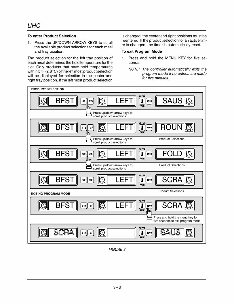
To enter Product Selection
1. Press the UP/DOWN ARROW KEYS to scrollthe available product selections for each mealand tray position.
The product selection for the left tray position ofeachmeal determines the hold temperature for theslot. Only products that have hold temperatureswithin 5_F (2.8_C)of the leftmost product selectionwill be displayed for selection in the center andright tray position. If the left most product selection
is changed, the center and right positions must bereentered. If the product selection for an active tim-er is changed, the timer is automatically reset.
To exit Program Mode
1. Press and hold the MENU KEY for five se-conds.
NOTE: The controller automatically exits theprogram mode if no entries are madefor five minutes.
BFST LEFT SAUSPress up/down arrow keys toscroll product selections
BFST LEFT ROUN
BFST LEFT FOLD
BFST LEFT SCRA
Product Selections
Product Selections
Press and hold the menu key forfive seconds to exit program mode
PRODUCT SELECTION
BFST LEFT SCRA
EXITING PROGRAM MODEProduct Selections
Press up/down arrow keys toscroll product selections
Press up/down arrow keys toscroll product selections
FIGURE 3

PROGRAMMING AND CALIBRATION
3---4
Sample product selection change
This example changes the lunch product selectionin the left position of slot 3 from 10-1 to NUGG.Since the hold temperature for NUGG is different
than 10-1, the center and right product selectionsare cleared. Only items with hold temperatureswithin 5_F (2.8_C) of the left product selection canbe entered for the center and right position.
PROG MODE
Press menu to key for five secondsto enter the program mode
Press page key to scroll slot pageselections
SLOT 1Press page key to scroll slot pageselections
SLOT 2
SLOT 3Press menu key to scroll mealselection and tray position
BFST LEFT SAUSPress menu key to scroll mealselection and tray position
Meal Selection Tray Position
Press page key to scroll slot pageselections
BFST CENT SAUSPress menu key to scroll mealselection and tray position
Meal Selection Tray Position

UHC
3---5
BFST RGHT SAUSPress menu key to scroll mealselection and tray position
Meal Selection Tray Position
LNCH LEFT 10-1Press menu key to scroll mealselection and tray position
Meal Selection Tray Position
LNCH LEFT 4-1
Press up/down arrow keys to scroll product selections
LNCH LEFT NUGGPress and hold menu key for fiveseconds to exit program mode
FIGURE 4

PROGRAMMING AND CALIBRATION
3---6
ENTERING AND EDITING PRODUCT INFORMATIONChangingor entering newproduct selections, holdtimer and temperature setting are password pro-tected functions.
To enter the password
1. Press and hold the MENU KEY for five sec-onds. The display reads PROG MODE.
2. Press the ENTER/PAGE KEY to scroll to VIEWPAGE.
3. Press the MENU KEY to select the securitylock, SECR LOCK.
4. Press the UP and DOWNARROWKEYS to en-ter the security code 123.
5. Press ENTER/PAGE KEY..
A new product entry requires entry of:D the product name,D hold time,D hold temperature from 55-250_F (13-121_C),D meal selection,The following example enters a new product,namedXXY, with a hold timeof 25minutes andholdtemperature of 180_F (82_C).
Press and hold menu key to enterprogram mode
PROG MODE
VIEW PAGE
Press enter/page key to scroll view page
SECR LOCK 156
SECR LOCK 123
ENTERING THE PASSWORD
Press menu key to scroll to thesecurity lock
Press up/down arrow keys to enter password
FIGURE 5

UHC
3---7
EDIT PAGE SAUS
SECR LOCK 123
ENTERING THE PRODUCT NAME
Press page key to scroll to the edit page
Press menu key to scroll to anunused product (blank) mnenonic
PROD NAME .Press up arrow key toscroll to the letter X
NOTE: The decimal point indicates which display segment is being entered.
PROD NAME X.
Press down arrow key to scroll to the next display segment
PROD NAME X.Press up arrow key to scroll to the letter X
PROD NAME XX.Press down arrow key to scroll to the next display segment
PROD NAME XX.
Press up arrow key to scroll to the letter Y
PROD NAME XXY.
FIGURE 6

PROGRAMMING AND CALIBRATION
3---8
ENTERING THE PRODUCT HOLD TIME
PROD NAME XXY.Press page key to scroll to the time page
TIME PAGE XXYPress menu key to scroll to producttime selection
XXY TIME 20
Press up/down arrow key to change time to 25 minutes
XXY TIME 25
FIGURE 7

UHC
3---9
ENTERING THE PRODUCT HOLD TEMPERATURE
XXY TIME 25Press page key to scroll to the temp page
TEMP PAGE XXYPress menu key to scroll to producttop plate temperature selection
XXY Ttop 155
Press up/down arrow key to change top plate temperature
XXY Ttop 180Press menu key to scroll to productbottom plate temperature selection
XXY Tbot 155
Press up/down arrow key to change bottom plate temperature
XXY Tbot 180
FIGURE 8

PROGRAMMING AND CALIBRATION
3---10
XXY Tbot 180
ENTERING MEAL USAGE
Press page key to scroll to the meal page
MEAL PAGE XXYPress menu key to scroll to productmeal selection
XXY MEAL ALLPress up/down arrow keys to select BFST
XXY MEAL BFST
FIGURE 9

UHC
3---11
MORE PRODUCT PROMPT TIME FEATUREA cookmore timemay be entered for each producttype that will alert the operator to cook more prod-uct before the holding time reaches zero. When theproduct timer equals the cook time the audiblealarm will chirp for 3 seconds and the displaymes-sagewill alternately displayPRODUCTNAME, TIM-ER TIME, COOK and MORE until the timer timesout. If more than one tray of a product type is activethe cook more alarm will not occur until all activetimers reach the cook time.If a position is indicat-ing, COOK MORE and another timer of the sameproduct is started, the COOK MORE message willbe cleared. During transition from breakfast tolunch the COOKMORE indication is disabled. Usethe following procedure to change or enter thecook time of a product svelection:
1. Press and hold the menu key for 5 seconds.
2. Press the page key to scroll to view page.
3. Press the menu key to scroll to the securitylock.
4. Press the up and down arrow keys to enter themanager security code: 3 3 1.
5. Press the page key to scroll to cook page.
6. Press the menu key to scroll to product selec-tion.
7. Press the up and down arrow keys to increaseor decrease the prompt time (in minutes) tocook more product.
8. When complete, press and hold the menu keyfor 5 seconds to return to normal operation.
DEFAULT SELECTIONS FOR THE PROMPT TIME
MNEMONICS Description AvailableSettings
AccessLevel
Left Center Right*Settings Level
COOK PAGE Cook Page
SAUS COOK 4 Product 1 Cook Time 0---30 Minutes 3
ROUN COOK 4 Product 2 Cook Time 0---30 Minutes 3
FOLD COOK 3 Product 3 Cook Time 0---30 Minutes 3
SCRA COOK 3 Product 4 Cook Time 0---30 Minutes 3
RBAC COOK 0 Product 5 Cook Time 0---30 Minutes 3
CBAC COOK 1 Product 6 Cook Time 0---30 Minutes 3
MUFF COOK 3 Product 7 Cook Time 0---30 Minutes 3
BISC COOK 22 Product 8 Cook Time 0---30 Minutes 3
BURR COOK 0 Product 9 Cook Time 0---30 Minutes 3
10---1 COOK 2 Product 10 Cook Time 0---30 Minutes 3
4---1 COOK 4 Product 11 Cook Time 0---30 Minutes 3
GRCK COOK 5 Product 12 Cook Time 0---30 Minutes 3
NUGG COOK 5 Product 13 Cook Time 0---30 Minutes 3
FISH COOK 5 Product 14 Cook Time 0---30 Minutes 3
McCK COOK 7 Product 15 Cook Time 0---30 Minutes 3
NOTE: The right display gives the time in minutes.

PROGRAMMING AND CALIBRATION
3---12
CHANGING THE DISPLAY TIMEThe rate at which an active timer alternately dis-plays product selection and hold time may be ad-justed as follows:
1. Enter the manager programming securitycode. See page 3---6.
2. Press the MENU KEY to scroll to product dis-play time, PROD TIME.
3. Press the UP and DOWN ARROW KEYS tochange the product display time.
4. Press the MENU KEY to scroll to timer displaytime, TIMR TIME.
5. Press the UP and DOWN ARROW KEYS tochange the timer display time.
6. Press andhold theMENUKEY for five secondsto return to normal operation.
SECR LOCK 123
Press and hold menu key scroll to PROD TIME
PROD TIME 10
TIMR TIME
Use the arrow keys to change product display time
TIMR TIME 10
CHANGING THE DISPLAY TIME
Press menu key to scroll to TIMR TIME
Use the arrow keys to change timer display time
Press and hold the menu key to return to normal operation
FIGURE 10

UHC
3---13
CHANGING THE DISPLAY INTENSITYThe brightness of each of the three intensity levelsused for product status may be adjusted as fol-lows:
1. Enter the manager programming securitycode. See page 3---6.
2. Press the MENU KEY to scroll to display inten-sity level. The display reads DISP IntX. Thereare three display intensity levels available.
Level # Display Range Default
1 (dimmest) Int1 10---25 10
2 (mid-level) Int2 10---25 10
3 (brightest) Int3 67-100 100
TABLE 1
3. Press the UP and DOWN ARROW KEYS tochange the intensity level.
4. Press andhold theMENUKEY for five secondsto return to normal operation.
DISP Int1 20
SECR LOCK 123
Press and hold menu key scroll to DISP Int1
DISP Int1 10Use the arrow keys to change product display intensity
CHANGING THE DISPLAY TIME
Press and hold the menu key to return to normal operation
FIGURE 11

PROGRAMMING AND CALIBRATION
3---14
SERVICE PROGRAMMING AND CALIBRATION
THE FOLLOWING PROGRAMMING AND CAL-IBRATION INFORMATION IS FOR AUTHORIZEDSERVICE PERSONNEL ONLY.
TO ACCESS SERVICE PROGRAMMING
Service programming is password protected. Usethe following procedure to enter the password andaccess service programming (level 3 program-ming).
1. Press and hold the MENU KEY for five sec-onds.
2. Press the ENTER/PAGE KEY to scroll to VIEWPAGE.
3. Press the MENU KEY to scroll to the securitylock, SCR LOCK.
4. Press the UP and DOWNARROWKEYS to en-ter the security code 247 or 331.
5. Press ENTER/PAGE KEY.
Press and hold menu key to enterprogram mode
PROG MODE
VIEW PAGE
Press enter/page key to scroll view page
SECR LOCK 156
SECR LOCK 331
ENTERING THE PASSWORD
Press menu key to scroll to thesecurity lock
Press up/down arrow keys to enter password
Use 331 or 247
FIGURE 12

UHC
3---15
OFFSET CALIBRATION
The offset value is the difference between the set-point and the actual temperature. If the actual tem-perature is lower than the setpoint a negative offsetis needed. If the actual temperature is higher thanthe setpoint a positive offset is needed.
Use the surface probe to compare the top and bot-tom temperatures to the setpoint value of 155_F(68_C). Take allmeasurements from the slot centerposition. Record the value. Repeat for all slots. Ifthe actual temperature varies from the setpoint by¦5_F (3_C) adjust the temperature offset as follows:
1. After accessing the service level program-ming, press the ENTER/PAGE key to scroll tothe slot number requiring adjustment.
NOTE: It is possible to access all slots fromany display.
2. Press the MENU key to advance to top or bot-tom of offset selection. Use the ARROW keysto select the offset value. Press the ENTER keyto advance to the next slot. Repeat for all slots.
3. Press the MENU key for five seconds to exitservice programming.
NOTE: It is not necessary to exit the program-ming mode if you wish to advance toDisplay Test or Timer Test.
DISPLAY TEST MODE
The display test verifies all display segments areoperational.
NOTE: Executing the display test requires access tolevel 5 programming. Contact Blodgett Ser-vice to acquire the necessary password.
1. Press the ENTER/PAGE key to scroll to TESTPAGE.
2. Press theMENUKEY to scroll toDISPLAY TESTOFF.
3. Press and hold the bottom two outside timersuntil the displays change. All segments shouldilluminate and stay lit to give the operator timeto check both sides of the UHC. After the dis-
plays have been checked, turn the unit off andback on again to exit the display test mode.
4. After verifying all slot display segments illumi-nate, press the ARROW KEY to stop the test.The display reads DISPLAY TEST OFF.
5. Press the MENU key for five seconds to exitservice programming.
NOTE: It is not necessary to exit the program-ming mode if you wish to advance tothe Timer Test.
TIMER FAST TEST
This test changes the timing on the TIMER KEYSfrom minutes to seconds to allow for quick test ofthe timer keys. Access service level programmingto execute the timer test.
1. Press the ENTER/PAGE key to scroll to TESTPAGE.
2. Press the MENU KEY to scroll to FAST TESTOFF.
3. Press the ARROW KEY to toggle to FAST TESTON.
4. It is necessary to exit the service programminglevel to test the timer keys. Press the MENUKEY for five seconds to exit service program-ming and test the timer keys.
5. Press any TIMER KEY to activate and verify thetimer count down while in seconds mode. Thetimer counts down and an alarm sounds. To si-lence the alarm press the TIMER KEY.
6. To cancel TIMER FAST TEST re-enter the ser-vice level programming. See page 3---14.
7. Press the ENTER/PAGE key to scroll to TESTPAGE.
8. Press the MENU KEY to scroll to FAST TESTON.
9. Press the MENU KEY to toggle to FAST TESTOFF.
10. Press the MENU KEY for five seconds to exitthe service level programming.

PROGRAMMING AND CALIBRATION
3---16
Press the enter key to scroll to the slot # requiring offset calibration
TOP OFST 0
TOP OFST 10
Press the menu key to advance to top offset display
BOT OFST 0
OFFSET CALIBRATION
Use arrow keys to select offset valuePress the menu key to advance to bottom offset display.
Press the Enter/Page key to advance control to next slot
SLOT #
BOT OFST 0
Press the menu key for five seconds to exit service programming
FIGURE 13

UHC
3---17
DISP TEST OFF
Press the arrow keys to end the test
Press the enter key to scroll to the display test
DISPLAY TEST
TEST PAGE
Press the menu key to advance to DISP TEST OFF
DISP TEST OFF
Press the arrow keys to begin the test
DISP TEST ON
Segments light individually
Press the menu key for five seconds to exit service programming
FIGURE 14

PROGRAMMING AND CALIBRATION
3---18
Press the enter key to scroll to the display test
TIMER FAST TEST
TEST PAGE
Press the menu key to advance to FAST TEST OFF
FAST TEST OFF
Press the arrow keys to toggle to FAST TEST ON
FAST TEST ON
Press any timer key to activate and verify the timer count down whilein seconds mode. Press the menu key for 5 seconds to re-enter theprogram mode. Access the service level programming.
Press the menu key for five seconds to exit service programming
Press the menu key for 5 seconds to exit service programming and test timer keys
FAST TEST ON
Press the enter key to scroll to TEST PAGE.
TEST PAGE
Press the menu key to advance to FAST TEST ON
FAST TEST ON
Press the arrow keys to toggle to FAST TEST OFF
FAST TEST OFF
FIGURE 15

UHC
3---19
CHANGING FROM _F TO _CThe following changes the temperature units from_F to _C.
1. Enter the service programming security code.See page 3---14.
2. Press the MENU KEY to scroll to display units.
3. Press the UP and DOWN ARROW KEYS tochange from _F to _C.
4. Press andhold theMENUKEY for five secondsto return to normal operation.
Press and hold menu key to scroll to display units
DISP UNIT FPress arrow keys to toggle units
SECR LOCK 331
CHANGING TEMPERATURE UNITS
Press menu key for 5 seconds to return to normal operation
DISP UNIT C
FIGURE 16

PROGRAMMING AND CALIBRATION
3---20
PROGRAMMING ALARMSFOOD AND DRUG ADMINISTRATION (FDA)ALARM
TheFDAalarm indicates the slot temperature isbe-low the FDA temperature setpoint (140_F) for atime greater than the FDA time setting.
1. Enter the service programming security code.See page 3---14.
2. Press the MENU KEY to scroll to FDA PAGE.
3. Press the ENTER key to advance the control.Use the ARROW keys to enter FDA time from0-5minutes. Thedefault is 2minutes. Press theENTER key to advance the control.
4. Use the ARROW keys to enter FDA tempera-ture from 55-140_F. The default is 140_F. Pressthe ENTER key to advance the control.
5. Press and hold the MENU key to exit program-ming.
Press and hold menu key to scroll to the FDA page
FDA PAGE
SECR LOCK 331
FDA ALARM
Use the arrow keys to enter FDA time from 0-5 minutes
FDA TIME 2
Press the Enter/Page key to advance to the FDA time
Press Enter/Page key to advance control
FDA TIME 3
Use the arrow keys to enter FDA temperature from 55-140_F
FDA TEMP 140
Press Enter/Page key to advance control
FIGURE 17

UHC
3---21
HI AND LOW TEMPERATURE ALARMS
If the slot temperature is above or below the presetlimits for a product selection, the control enters thehigh or low alarm condition. The alarm setpointscan be programmed from the ALRM PAGE. Theyare entered as _Foffsets from theproduct setpoint.The default settings are 10_F.
NOTE: When switching menus or products thetemperature alarm is displayed if the newproduct or menu requires a holding tem-perature outside of the current alarm band.If the condition remains for two or moreminutes an audible alarm sounds. Pressany timer key to silence the alarm. The dis-play returns to normal when the new holdtemperature has been reached.
1. Enter the service programming security code.See page 3---14.
2. Press the MENU KEY to scroll to ALRM PAGE.
3. Press the ENTER KEY to advance the control.The display reads ALRM ENBL ON.
NOTE: Selecting ALRM ENBL OFF disablesthe visual and/or audible productalarms for all slots.
4. Use the ARROW KEYS to toggle bewteen offand on. Press the MENU KEY to advance thecontrol.
5. The display reads ALRM LoSP X. Use the AR-ROW KEYS to enter the desired low tempera-ture alarm from 1-10_F. Press the MENU KEYto advance the control.
6. The display reads ALRM HiSP X. Use the AR-ROW KEYS to enter the desired high tempera-ture alarm from 1-10_F. Press the MENU KEYto advance the control.
7. The display reads ALRM TIME X. The alarmtime allows an alarm condition to exist for up to5 minutes before activating the audible alarm.The default setting is 2 minutes.
Use the ARROW KEYS to enter the desiredalarm time from 0-5 minutes. Press the ENTERKEY to advance the control.
8. Press and hold the MENU key to exit program-ming.
Press and hold menu key to scroll to the alarm page
ALRM PAGE
SECR LOCK 331
HIGH AND LOW TEMPERATURE ALARM
Use the arrow keys to toggle from ON to OFF
ALRM ENBL ON
Press the Enter/Page key to advance the control
Press Menu key to advance control
ALRM ENBL ON

PROGRAMMING AND CALIBRATION
3---22
Use the arrow keys to enter desired high temperature alarm
ALRM LoSP 10
Press the Enter/Page key to advance the control
ALRM HiSP 0
ALRM HiSP 10
Press the Menu key to advance the control
Use the arrow keys to enter alarm time
ALRM TIME 0
ALRM TIME 2
Press the Enter/Page key to advance the control
ALRM PAGE
Press and hold the menu key to exit programming
HIGH AND LOW TEMPERATURE ALARM
Use the arrow keys to enter desired low temperature alarm(the range is 1-10 with a default of 10)
ALRM LoSP 10
FIGURE 18

UHC
3---23
This page intentionally left blank.

TROUBLESHOOTINGCHAPTER 4

UHC
4---1
TROUBLESHOOTING ELEMENTS AND WARNING ALARMS
CAUTION: Due to electrostatically sensitivecomponents. All technicians performing ser-vice work must be grounded. Grounding maybe accomplished using a grounding strap orother suitable means. Connect to anothergrounded unpowered piece of equipment. (ie.equipment other than the one you are currentlyworking on.)
During initial heat from a cold start, the unit appliesfull voltage to the elements. As the shelf ap-proaches the setpoint temperature, the controlpulses the output of the elements. This allows foran accurate set point response withminimum tem-perature overrun.
NOTE: The control also pulses output during nor-mal operation to provide an even tempera-ture response.
To Troubleshoot an Element
1. Verify offset calibration. Refer to page 3---15. Ifcorrect continue with step 2.
2. Attach an amp clamp to the input. Observe thesteady amp draw during the initial startup andthe subsequent pulsing of this input at temper-atures close to set point.
Themain control applies voltage to the element as-semblies bywayof a TRIAC solid state device. Thiscircuit normally fails in the closed position and canresult in an overheat condition. If the elements donot receive the pulse input, the main control is de-
fective. To replace a defective element, the upperand lower portion of the shelf must be replacedwhichever is defective.
Several warning alarms can result from a defectiveelement:
D High and low temperature alarmD FDA alarmD Sensor alarmD Rise time alarmIf an alarm conditions occurs, a display alarm ap-pears. An audible alarmmay sound depending onthe alarm condition. Press the timer key to silencethe audible alarm. Timers cannot be started whena slot is in an alarm condition.
HI AND LOW TEMPERATURE ALARM
If the slot temperature is above or below the presetlimits for a product selection, the controller entersthe high or low alarm condition. The display readseither SLOT TEMP HIGH or SLOT TEMP LOW.
1. An audible alarm sounds if the alarm conditionremains for two or more minutes.
NOTE: The low temperature audible alarm is inhib-ited at power up. The SLOT TEMP LOWmessage is displayed alternately with theproduct selection until the slot is within thepreset limits.
SLOT TEMP LOW
SLOT TEMP HIGH
Press any timer key to silence audible alarm
HIGH/LOW TEMPERATURE ALARM
Press any timer key to silence audible alarm
FIGURE 1

TROUBLESHOOTING
4---2
FOOD AND DRUG ADMINISTRATION (FDA)ALARM
TheFDAalarm indicates the slot temperature isbe-low the preset limit to hold the product. The audiblealarm sounds and the display reads TEMP UNDRFDA. Active timers are automatically reset.
1. To turn off the audible alarm press any TIMERKEY. The alarmmessage remains until the slottemperature is within the preset limits. If nokeys are pressed the audible and visual alarmremain.
See page 4--8 for troubleshooting.
SENSOR RANGE ALARM
The sensor fail alarm indicates a sensor tempera-ture value above or below the operating limits ofthe slot, 50---250_F (10-121_C).
1. To turn off the audible alarm press any TIMERKEY. The alarm message is displayed until theslot temperature is within the operating limits.
2. Press the temp/enter key to display the errormessageHHHH or LLLL. HHHH indicates highresistance, high temperature or open/shortedprobe. LLLL indicates low resistance, low tem-perature or open/shorted probe. Measure theresistance of the probe, see page 5---5.
3. Scroll through the menu key until TURN SLOTOFF is displayed. Press the enter key withinfive seconds.
Service is required to correct a sensor alarm.Refer to the flow diagrams in this chapter fortroubleshooting.
SENS ALRM
Press any timer key to silence audible alarm
SENSOR RANGE ALARM
FDA ALARM
TEMP UNDR FDA
Press any timer key to silence audible alarm
FIGURE 2

UHC
4---3
RISE TIME ALARM
The rise time alarm indicates that the slot tempera-ture failed to reach operating temperature withinthe preset time limits of the system at power up.The system measures the time that each platetakes to go from 100---125_F. If this time is greaterthan 15 minutes the alarm is activated and SLOTRISE RATE is displayed.
1. To turn off the audible alarm press any TIMERKEY.
Service is required to correct a rise time alarm.See page 4--8 for troubleshooting.
Use the following procedure to view the rise timesfor each plate:
1. Press and hold the MENU key to enter the pro-gram mode.
2. Press the PAGE key to scroll to the TEST PAGE.
3. Press theMENUkey to scroll the time recordedfor each slot at start up.
RISE TIME ALARM
SLOT RISE RATE
Press any timer key to silence audible alarm
SLOT RISE RATE
Press any menu key to enter the program mode
TEST PAGE
Press any menu key to scroll the recorded rise times
RATE TOP1 12:00
FIGURE 3

TROUBLESHOOTING
4---4
TROUBLESHOOTING FLOW DIAGRAMS
No Replace the display cable.
Problem:Unit fails to power up.
Verify input powerto terminal block
No
Yes
Checkbranch circuit
Turn on power switch.Verify blower operationand power on primary
transformer
No
Yes
Replacepower switch
Is there voltage on thesecondary transformer?
No
Yes
Replace transformer.Leave secondary wiring disconnected.Verify voltage on secondary transformer.Isolate any shorts between transformer leads.Replace effected componentsReplace main board.
Problem:Segment out in display.
No
Yes
Enter the display testmode. See page 3---15.Verify faulty segmentlocation. Swap front andrear display driver cables.
Is the segment still out?
Visually and electricallycheck the suspectdisplay cable.
Is the cable ok?
Replace the driver board.
Yes
Replace the display.
FIGURE 4

UHC
4---5
No Replace theshelf assembly
No
No
Problem:Unit does not heat
Is the power switch on?
Yes
Turn switch on
NoIs the unit plugged in?
Yes
Plug unit in
Is the breaker on? Turn breaker on
Yes
NoIs there an illuminateddisplay on each shelf
NoIs the heating problemon all shelves?
Is the resistance value of the probe correctfor the effected shelf (see TABLE 1 onpage 6---3 of the Technical Appendix)
Yes
Replace themother board
Yes
No Replace themotherboard
Is there input voltage (208 or 240)applied to the effected element?
Yes
Replace the effected shelf assemblyYes
No
NoIs 208 or 240V applied to theprimary of the transformer?
Check power switch for failureand wires from power switch toprimary of transformer for
continuity. Replace if necessary.Yes
Disconnect OR-20, BL-20 & Y-20 from the main board.
Is there approx. 18V output from the secondary of thetransformer between OR-20 & Y-20?
Is there approx. 9V output from the secondary of thetransformer between BL-20 & OR-20 and BL-20 & Y-20?
Replace thetransformer
Yes
Reconnect OR-20, BL-20 &Y-20 to the main board.
Is there approx. an 18V and9V on the secondary?
Yes
Replace themain board
NoDisconnect CN-1 (AC powerin) to each driver board.
Is there approx. 18V and 9Von the main board?
Yes
No Replace themain board.
Successively plug in driver board no 4, 3, 2 & 1. Verifythe secondary voltage at each step. If the secondaryvoltage is lost, replace effected driver board.
No Replace effectedharness
Visually and electrically check RTDand heater harness. Are they ok?
Yes
FIGURE 5

TROUBLESHOOTING
4---6
No
Problem:An individual shelf display will notchange from breakfast to lunch orwill not allow the operator to set
or reset the timers.
Yes
Is the problem onall three displaysections?
NoAre connectionsfrom the controlmembrane to theLED displayproper and ingood condition?
Are ribbon cable connectionsfrom the display to the shelfdriver connected to their ap-propriate driver board?
Yes
Replace controlmembrane switchassembly.
Yes
Connect the ribboncables to theirappropriate driver
board.
Problem fixed.
Done
Problem still exists.Replace LEDdisplay assembly
Problem fixed.
Done
Problem still exists.Replace shelfdriver board.
Done
Replace LEDdisplay assy.
Problem fixed.
Done
Problem still exists.Replace thedriver board.
Done
No Clean or reinstallribbon connection.
FIGURE 6

UHC
4---7
Problem:An individual shelf is in
an overheat orunderheat situation.
No
Yes
Is the resistance vs.temperature on theprobe correct?
Refer to page 5---5 forprocedure.
(see TABLE 1 on page6---3 of the
Technical Appendix forconversions)
No
Yes
Does the input voltageto the element cycle onand off and pulse whenclose to set point?
No
Replace shelf assembly.
Is the programmingcorrect for this shelf?(see Programming andCalibration section)
Correct the programming.(see Programming andCalibration section)
Replace themain board.
Yes
Replaceshelf assembly.
FIGURE 7

TROUBLESHOOTING
4---8
Problem:Unit displayssensor alarm.
No
Yes
Replace theshelf assembly.
Replace themother board.
Problem:Unit displays
FDA or rise time alarm
No
Yes
Is the effected elementreceiving 208 or 240input voltage?
Is the wiring harnessbetween the element andmother board correct?
Bad probe or heater.Replace the shelfassembly.
Replace themother board.
No Correct the wiring.
Yes
Is the resistance vs.temperature on theprobe correct?
Refer to page 5---5 forprocedure.
(see TABLE 1 on page6---3 of the
Technical Appendix forconversions)
No
Yes
Replace theRTD harness.
Does the resistance ofthe probe and harnessapprox. match TABLE 1on page 6---3 of theTechnical Appendix?
FIGURE 8

UHC
4---9
Problem:Keypad Timer, Enter/Page or Menu keysnot working
No
Yes
Press problem key toverify fault.
Is audible click heard?
Swap suspect displaycable to same positionon different driver
board.
Press problem key. Isaudible click heard?
Yes
Replace driver board.No problem.
Replace membraneswitch.
Press problem key.Is audible clickheard?
No
Yes
Replaceribbon cable.
Problem:Keypad Arrow keysnot working
No
Yes
Enter service levelprogramming.(See page 3---14)Press problem key to
verify fault.
Is audible click heard?
Swap faulty display cableto same position on dif-ferent driver board.
Press problem key. Is au-dible click heard?
Yes
Replace driver board.No problem.
Replace membraneswitch.
Press problem key.Is audible click heard?
No
Yes
Replace driver board.
No
Problem fixed.
Done
FIGURE 9

TROUBLESHOOTING
4---10
TROUBLESHOOTING A LOCKED OUT SLOT
1. Remove the rear ribbon cable from the driverboard.
If the front membrane starts to work, you havenow isolated the problem to one of three of therear components.
If the front is still locked up then remove thefront ribbon and try using the rear timers.
If theywork then you have isolated theproblemto one of three front components.
2. Before replacing the membrane switch,Plug the newmembrane into the displayboardand try it in your hand. If it continues to lock upthen the problem is, in either the ribbon cable,or the display board.

UHC
4---11
TROUBLESHOOTING SENSOR ALARMS
The following is a test procedure to be used on theUHC-1 cabinet to determine the cause for many ofthe sensor alarms we are experiencing. You willneed the probe resistance chart, found on page6---3 to perform the following tests.
1. Determine the slot experiencing the “SENSORALARM”.
2. Determine the plate causing the alarm. To dothis you need to press the ENTER key 4 timesin succession and read the displays.
A.) Push ENTER key once display reads: TOPACT ** HHHH.
B.) Push ENTER key again display reads:BO-T ACT 200.
C.) PushENTERkeyagain display reads:TOPSET 200.
D.) Push ENTER key again display reads:BOT SET 200.
This has now determined that the ”SENSORALARM” is being caused by a high probe re-sistance reading. (This example is indicative ofa potential probe problem on the top plate ofthe slot experiencing the alarm).
3. Using a Pyrometer get the actual temp. of theplate in question This is the temp you will bereferencing.
4. Remove the probe harness from the motherboard and get the resistance reading from thecorrect probe leads (reference the schematicon page 6---1). The resistance value and tem-perature should match according to the chart.
If the resistance reading did not coincideproceed to STEP 5.
If the resistance coincides with the actual tempthe problem is either in the harness connectionor the mother board. Before replacing themother board check all the pins in the connec-
tor, reinstall the harness to the board, take atooth pick, snap it in half and insert each pieceinto the back of the probe wires. Check thetempdisplays again to see if the TOPACT coin-cides with the actual temperature. If so theproblem was in the connection and the probeharness should be replaced. If you still haveHHHH the problem is in the mother board andit should be replaced.
A.) ** HHHH= high resistance or open probe
B.) LLLL = low resistance or shorted probe
5. Disconnect the probe from the harness on theside of the unit and read the resistance throughthe probe while verifying the actual plate tem-perature. If the resistance reading at the probedoes not match the temperature according tothe chart, make sure you have a good connec-tion with your meter. If probe proves faulty, re-place the liner assembly. The probe and ele-ment are vulcanized to the liner and cannot bereplaced separately.
If the plate temperature and probe resistancematch according to the chart, check and tight-en connections at the side probe harness thenread resistance at top of harness again. If theresistance now coincides with the tempera-ture, the problem was in the connection. If theresistance is still incorrect the problem is in theharness and should be replaced.
6. If the problem is intermittent or you cannot findanything wrong test the probe. Shut the slot offand cool it downwith a pan of water then allowit to reheat. As it’s heating note the top andbot-tom temps using your pyrometer. As you notethe temperatures, read the probes resistancein 50 deg. increments. You should comparethese readingswith your probe chart. If theydonot match run the test again. If they still do notmatch the probe is going bad and the liner as-sembly should be replaced.

TROUBLESHOOTING
4---12
TROUBLESHOOTING THE DRIVER BOARD AND CONTROL
The following is a test procedure to be used on theUHC-1 cabinet to determine if there is a problemwith driver board, the display control, the controlmembranes, or the connecting harnesses.
1. Turn off power to the unit, locate the driverboard to the shelf to be tested, disconnect thecommunications port (this being the 18 pinconnector with the blue jumper wire), turn thepower back on. The shelf should now read”Display Test Mode”.
2. Starting with the front left timer push ALL but-tons one at a time in order with the last one be-ing the right rear timer. Each time you press akey the four DOTS at the bottom of the displaywill light up. If at any time during this test youget a ”Key Press Error” reset the unit, by turn-ing off then back on and start again. If the ”KeyPress Error” comes up at the same place, theunit did not see the previous key activate andthe followingprocedure should beconsidered:
A.) Clean the ribbon cable connections at thedisplay control. If the problem persistsmove on to next.
B.) Determine if the gray ribbon cable is goodby swapping it with one from another shelfand running the test again. If the ”KeyPress Error” goes away replace the rib-bon cable. If not move on to next.
C.) Remove the display control from the bezelassy. and inspect both ribbon connectionareas for burns or corrosion. If controllooks bad you can prove it by swapping itout with one from another shelf. If the ”KeyPress Error” goes away replace the dis-play control. If not replace the membrane.
3. After you hit the last key the shelf will go into anLED test, at this time all led segments will lightup. If some of the segments do not light cleanthe connection between the gray ribbon cableand the display control, and check the gray rib-bon for cuts or burns. If they still will not lightreplace the control.
4. During the LED test look at all 6 displays. If thesame led segment is out in all 6 displays thedriver board is bad and should be replaced‘

UHC
4---13
This page intentionally left blank.

PARTS REPLACEMENTCHAPTER 5

UHC
5---1
ELEMENT OR PROBE ASSEMBLY
1. Remove the right and left hand exterior panelsby removing the two lower phillips head screws.
2. Remove the top exterior panel by removing thetwo upper phillips head screws.
3. Loosen the two hex head bolts located on ei-ther side of the bezel assembly.
4. Trace the ribbon cable from the bezel assem-bly to its associated driver board. Remove theribbon cable from the driver board.
NOTE: Mark the location of the ribbon cable toensure it is replaced in theproper loca-tion.
5. Remove the ribbon cable clamps from the rib-bon cable bundle on the right side of the unit.
6. Repeat steps 3---5 for the adjacent bezel as-sembly.
7. Remove both bezel assemblies to allow for un-obstructed access to the shelf assembly.
8. Disconnect the two probes and element wireconnections from the affected shelf assembly.
9. Remove the four phillips head screws that at-tach the shelf assembly to the frame.
10. Remove the shelf assembly from the frame bysliding it out from either side.
NOTE: If you are removing the #1 shelf as-sembly, you must also remove the twowire clamps attached to the right sideof the shelf assembly before removingthe shelf from the frame.
11. Remove the insulation cover from the shelf as-sembly by removing the two phillips headscrews on either side of the cover assembly.
12. Remove the four pieces of insulation from theshelf assembly.
NOTE: The foil wrapped insulation is VERYFRAGILE. Please use extra care whenhandling.
13. Remove the twelve phillips head screws fromthe top shelf section. See FIGURE 1.
Screw
Disassembling the Shelf Assembly
Top Shelf Section
Bottom Shelf Section
FIGURE 1

PARTS REPLACEMENT
5---2
14. Discard the defective shelf section.
15. Install the new shelf section. Be sure to alignboth the front and rear faces of the shelf as-sembly so that both the top and bottom shelfsections are flush.
16. Install the foil wrapped shelf insulation and in-sulation cover assembly.
17. Insert the shelf assembly into the unit frame.Install the four phillips head screws throughthe shelf assembly into the unit frame.
18. Connect the two probe and element wire con-nections at the right side of the shelf assembly.
19. Feed the ribbon cables from the bezel assem-blies over the top of the shelves to their associ-ated driver boards.
NOTE: Be careful not to pinch the ribboncable between the bezel and the shelfassembly.
20. Inspect the gasket assembly on the bezel. Re-place if necessary. See Bezel Gasket Replace-ment on page 5---6.
21. Install the front and rear bezel assemblies.Tighten the four hex head bolts on either sideof the bezel assemblies.
22. Install the ribbon cable clamps on the ribboncable bundle located on the right side of theunit.
23. Install the side and top panels.
24. Check the unit for proper operation.
COOLING BLOWER
1. Remove the right and left hand exterior panelsby removing the two lower phillips head screws.
2. Remove the top exterior panel by removing thetwo upper phillips head screws.
3. Remove the black and white power connec-tions from the blower motor.
4. Loosen the two phillips head screws holdingthe blower bracket to the unit frame.
5. Remove the blower and bracket from the unit.
6. Remove the blower from thebracket by remov-ing the three phillips head screws.
7. Install the new blower on the bracket with thescrews provided.
8. Install the blower and bracket into the unitframe.
9. Connect the black and white power wires tothe blower motor.
10. Install the side and top exterior panels of theunit.
11. Check the unit for proper operation.

UHC
5---3
BEZEL ASSEMBLY
1. Remove the right and left hand exterior panelsby removing the two lower phillips head screws.
2. Remove the top exterior panel by removing thetwo upper phillips head screws.
3. Loosen the two hex head bolts at either side ofthe bezel assembly. Remove the bezel fromthe shelf.
4. Remove the two screws attaching the LED as-sembly to the bezel. Remove the ribbon cableattaching the membrane switch to the LED as-sembly.
5. Discard the bezel assembly.
6. Install the gasket into the new bezel assembly.See Bezel Gasket Replacement on page 5---6.
7. Install the membrane switch ribbon cable intothe LEDassembly. Attach the LED assembly tothe bezel with the two screws provided. SeeFIGURE 2 for proper placement and attach-ment of the membrane switch ribbon cable.
8. Install the bezel assembly on the frame bytightening the two hex head bolts located oneither side of the bezel assembly.
NOTE: Be sure not to pinch the ribbon cablebetween the bezel and the shelf as-sembly.
9. Install the side and top exterior panels.
10. Check the unit for proper operation.
Connect ribbon cables to the LED board
Flip the LED board as shown
Slide LED board under metal insert on bezel. Align the screws holes and attach the LED board.
Ribbon Cableunderneath boardMounting Screw Mounting ScrewBezel Insert
FIGURE 2

PARTS REPLACEMENT
5---4
MEMBRANE SWITCH
1. Remove the right and left hand exterior panelsby removing the two lower phillips head screws.
2. Remove the top exterior panel by removing thetwo upper phillips head screws.
3. Loosen the two hex head bolts located on ei-ther side of the bezel assembly. Remove thebezel assembly.
4. Remove the two screws holding the LED as-sembly to the bezel. Remove the membraneswitch ribbon cable from the LED board.
5. Remove the defective membrane switch fromthe bezel.
6. Clean all of the excess adhesive from the bez-el.
7. Install the new membrane switch on the bezel.
8. Inspect the bezel gasket and replace if neces-sary. See Bezel Gasket Replacement on page5---6.
9. Install the membrane switch ribbon cable tothe LED board. See FIGURE 2 on page 5---3for proper placement and attachment of themembrane switch ribbon cable.
10. Install the LED board into the bezel.
11. Install the bezel assembly on the frame bytightening the two hex head bolts located oneither side of the bezel.
NOTE: Be sure not to pinch the ribbon cablebetween the bezel and the shelf as-sembly.
12. Install the side and top exterior panels of theunit.
13. Check the unit for proper operation.
LED BOARD
1. Remove the right and left hand exterior panelsby removing the two lower phillips head screws.
2. Remove the top exterior panel by removing thetwo upper phillips head screws.
3. Loosen the two hex head bolts located on ei-ther side of the bezel assembly. Remove thebezel assembly.
4. Remove the two screws holding the LED as-sembly to the bezel. Remove the membraneswitch ribbon cable from the LED board.
5. Remove the ribbon cable clamps from the rib-bon bundle on the right side of the unit.
6. Trace the LED ribbon cable to its driver board.Remove the ribbon cable.
7. Feed the new LED board ribbon cable to itsdriver board.
8. Install the membrane switch ribbon cable tothe LED board. See FIGURE 2 on page 5---3for proper placement and attachment of themembrane switch ribbon cable.
9. Install the LED board into the bezel.
10. Install the bezel assembly on the frame bytightening the two hex head bolts located oneither side of the bezel.
NOTE: Be sure not to pinch the ribbon cablebetween the bezel and the shelf as-sembly.
11. Install the side and top exterior panels of theunit.
12. Check the unit for proper operation.

UHC
5---5
DRIVER BOARD
The driver boards are static sensitive. Makesure you use proper grounding procedureswhen handling these boards.
1. Remove the right and left hand exterior panelsby removing the two lower phillips head screws.
2. Remove the top exterior panel by removing thetwo upper phillips head screws.
3. Remove the ribbon and power connectionsfrom the affected driver board.
NOTE: Mark the location of these connectionsto ensure they are replaced in theirproper locations.
4. Release the four metal standoffs and removethe defective driver board.
5. Install the new board on the four metal stand-offs.
6. Install the ribbon and power connections onthe new board.
7. Install the side and top exterior panels of theunit.
8. Check the unit for proper operation.
TEMPERATURE PROBE
1. Unplug the probe from the harness.
2. Connect an ohm meter to the probe.
3. Press the timer key to silence the alarm. Theslot heats up.
4. Place the pyrometer. Refer to TABLE 1onpage6---3 of the Technical Appendix for resistancevalues.
MOTHER BOARD
The mother board is a static sensitive compo-nent. Make sure you use proper grounding pro-cedures when handling this board.
1. Remove the right and left hand exterior panelsby removing the two lower phillips head screws.
2. Remove the top exterior panel by removing thetwo upper phillips head screws.
3. Remove all power, sensor and communica-tions connections from the board.
NOTE: Mark the location of these connectionsto ensure they are replaced in theirproper location.
4. Release the six plastic standoffs to remove theboard.
5. Install the newmother board. Connect all of thepower, sensor and communications connec-tions.
6. Install the side and top exterior panels of theunit.
7. Check the unit for proper operation.

PARTS REPLACEMENT
5---6
BEZEL GASKET
1. Remove the right and left hand exterior panelsby removing the two lower phillips head screws.
2. Remove the top exterior panel by removing thetwo upper phillips head screws.
3. Loosen the two hex head bolts located on ei-ther side of the bezel assembly. Remove thebezel assembly.
4. Remove the two screws holding the LED as-sembly to the bezel. Remove the membraneswitch ribbon cable from the LED board.
5. Remove the old gasket from the bezel assem-bly.
6. Remove all of the old RTV from the bezel as-sembly.
7. Place a small bead of RTV along the bottomedge and in the top corners of the bezel wherethe new gasket will be placed.
8. Install the new gasket in the bezel. SeeFIGURE 3 for proper gasket placement.
9. Install the membrane switch ribbon cable inthe LED board. Attach the LED board to thebezel. See FIGURE 2 on page 5---3 for properplacement and attachment of the membraneswitch ribbon cable.
10. Install the bezel assembly on the frame bytightening the two hex head bolts located oneither side of the bezel.
NOTE: Be sure not to pinch the ribbon cablebetween the bezel and the shelf as-sembly.
11. Install the side and top exterior panels of theunit.
12. Check the unit for proper operation.
Gasket Gasket
Gasket Gasket
FIGURE 3

UHC
5---7
CHIP REPLACEMENT
The installation of the chips must be performedby a Blodgett Authorized Service and Parts(ASAP) agency. Failure to follow this mandatewill result in the nullification of your warranty.
Read all instructions for understanding prior tochip installation.
This service kit installs two IC chips which changethe functions on your UHC:D allow adjustment of product hold timesD replace the cook function with a COOKMOREproduct prompt feature
Check that all of the following parts were received:
P/N Description
35098 IC3/IC4 Chips and Puller
35111 ESD Wrist Strap
L-680 Lit Sheet
33355 Manual
THE MOTHER BOARD IS A STATIC SENSITIVECOMPONENT. MAKE SURE YOU USE PROPERGROUNDING PROCEDURES BEFORE BEGIN-NING THIS PROCEDURE.1. Disconnect power to the unit.2. Ground yourself using the ESD wrist strap pro-vided.
3. Remove the two screws securing the top panelof the unit.
4. Remove the top panel.5. Use the chip removal tool provided to removethe chip labeled IC3 (Integrated Circuit 3) asfollows:d Insert the chip removal tool into one of thesquare corners of the chip socket. Slowlypull the chip upward.
NOTE: Be sure that the chip you are remov-ing is labeled IC3.
e Move the chip removal tool to another cor-ner of the chip socket. Slowly pull the chipupward.
f Alternate corners until the chip is com-pletely removed from the chip socket.
6. Install the new IC3 chip as follows:a Remove the chip labeled IC3 from its pack-aging.
NOTE: Be sure that the chip you are instal-ling is labeled IC3.
b Be sure to line the new IC3 chip upwith theIC3 socket correctly. One corner of thechip has a 45_ angle. One corner of thesocket has a 45_ angle and an arrow. The45_ angle on the chipmust line up with the45_ angle and the arrow on the socket.See NO TAG.
c Push gently with your finger until the newchip is completely inserted into the socket.
7. Repeat steps 5 and 6 for the IC4 chip.8. Replace the top panel on the unit.9. Run the unit through the functional test.
OPERATION VERIFICATION1. Power up the UHC. Let the unit warm up to theset temperature.NOTE: As soon as the LED display lights up the
display should read BOC VER 2.002. Product Timera Press the product key to initiate the prod-uct program.
b Press the product key again within 3 sec-onds to verify that the displayed holdingtime decreases by 5 seconds.
c Repeat for each product program.

PARTS REPLACEMENT
5---8
IC3
IC4
Chip
Socket
FIGURE 4

UHC
5---9
This page intentionally left blank.

TECHNICAL APPENDIXCHAPTER 6
UHC
6---1
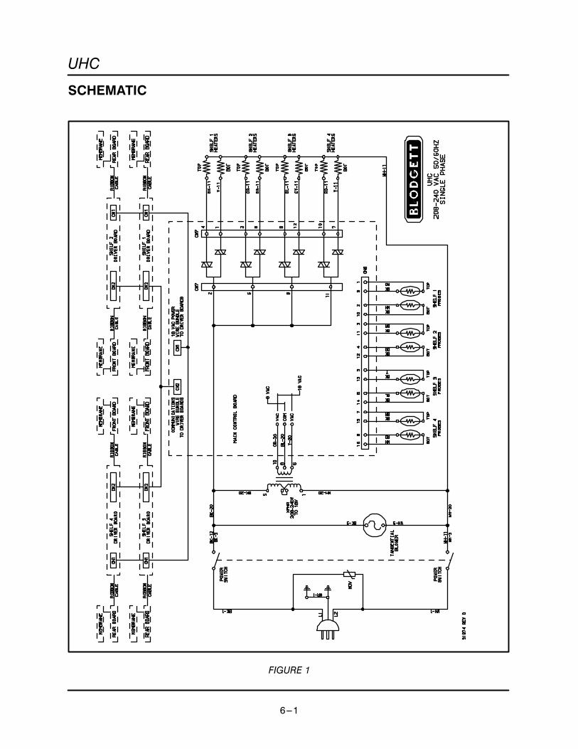
SCHEMATIC
FIGURE 1

TECHNICAL APPENDIX
6---2
WIRING DIAGRAM
FIGURE 2

UHC
6---3
TEMPERATURE PROBE
_F _C Res/Ohms _F _C Res/Ohms
61 16 106.0 189 87 133.5
68 20 107.8 194 90 134.7
75 24 109.3 199 93 135.6
81 27 110.5 207 97 137.3
86 30 111.6 212 100 138.5
91 33 112.8 217 103 139.6
100 38 114.7 225 107 141.1
109 43 116.7 230 110 142.3
117 47 118.2 235 113 143.4
122 50 119.4 243 117 144.9
127 53 120.5 248 120 146.0
135 57 122.1 253 123 147.2
140 60 123.2 261 127 148.7
145 63 124.4 266 130 149.8
153 67 125.9 271 133 151.0
154 68 126.3 279 137 152.5
158 70 127.1 284 140 153.6
163 73 128.2 289 143 154.7
171 77 129.7 297 147 156.2
176 80 130.9 300 149 156.9
181 83 132.0 350 177 167.0
TABLE 1


