Embed Size (px)
Citation preview
1 Introduction to satellite communication: 11.2 Kepler’s laws: 2
1.2.1 Kepler’s law Introduction:1.2.2 Kepler’s First Law:1.2.3 Kepler’s Second Law :
1.3 Newton’s law: 31.3.1 Newton's first law:1.3.2 Newton's second law:1.3.3 Newton's first law:
1.4 Orbital parameters: 41.5 Orbital Perturbations: 6
1.5.1 Effects of non-Spherical Earth:1.5.2 Atmospheric Drag:
1.6 Station Keeping: 71.7 Geo stationary and Non Geo-stationary orbits: 8
1.7.1 Geo stationary:1.7.2 Non Geo-Stationary Orbit:
1.8 Look Angle Determination: 111.9. Limits of visibility: 121.10 Eclipse: 131.11 Sub satellite Point: 141.12 Sun Transit Outage: 151.13 Launching Procedures: 18
1.13.1 Introduction:1.13.2 Orbit Transfer:
1.14 Launch vehicles and propulsion: 191.14.1 Transfer Orbit:
UNIT II SPACE SEGMENT & SATELLITE LINK DESIGN 23-502.1 Spacecraft Technology- Structure: 232.2 The Power Supply: 242.3 Attitude Control & Orbit Control: 25
2.3.1 Spinning satellite stabilization:2.3.2 Momentum wheel stabilization
2.6.1 Transponders:2.6.2 The wideband receiver2.6.3 The input demultiplexer2.6.4 The power amplifier
2.7. Satellite uplink and downlink Analysis and Design: 412.7.1 Introduction2.7.2 Equivalent Isotropic Radiated Power2.7.3 Transmission Losses
UNIT I SATELLITE ORBITS 1-22
2.4 Thermal Control and Propulsion: 262.5 Communication Payload & Support Subsystems: 272.6 TT&C Subsystem 31

2.8 The Link-Power Budget Equation: 432.9 Amplifier noise temperature 442.10 The Uplink 452.11 Downlink 462.12. Inter modulation and interference: 482.13. Propagation Characteristics and Frequency considerations: 48
2.13.1 Introduction2.13.2 Radio Noise
2.14. System reliability and design lifetime: 492.14.1 System reliability:2.14.2. Design lifetime:
UNIT III SATELLITE ACCESS 51-72
3.1 Modulation and Multiplexing: Voice, Data, Video: 513.1.1 Voice, Data, Video:3.1.2 Modulation And Multiplexing:
3.2 Analog – digital transmission system: 523.2.1 Analog vs. Digital Transmission:3.2.2 Digital Data/Analog Signals:
3.3. Digital Video Broadcasting (DVB): 543.4 Multiple Access Techniques: 56
3.4.1 Frequency division duplexing (FDD):3.4.2. Time division duplexing (TDD):3.4.3 FDMA:3.4.4 TDMA:3.4.5 Code Division Multiple Access (CDMA):
3.5. Channel allocation schemes: 643.5.1 FCA:3.5.2. DCA and DFS
3.6 Spread spectrum: 653.6.1 Spread spectrum Techniques:
3.7 Compression – Encryption: 663.7.1 Encryption and Transmission:3.7.2 Video and Audio Compression:3.7.3 MPEG Standards :
3.8 Encryption: 67
UNIT IV EARTH SEGMENT 73-90
4.1 Earth Station Technology: 734.1.1 Terrestrial Interface:4.1.2 Transmitter and Receiver4.1.3. Earth Station Tracking System:
4.2 Antenna Systems : 764.2.1 Feed System

4.2.2 Antenna Reflector :4.2.3 Antenna Mount:4.2.4 Antenna Tracking System :
4.3 Receive-Only Home TV Systems: 804.3.1 The Indoor unit:4.3.2 The outdoor unit:
4.4 Master Antenna TV System: 844.5 Community Antenna TV System: 854.6 Test Equipment Measurements on G/T, C/No, EIRP: 864.7 Antenna Gain: 89
UNIT V SATELLITE APPLICATIONS 91-131
5.1 INTELSAT Series: 915.2 INSAT: 93
5.2.1 INSAT System:5.2.2 Satellites In Service:
5.3 VSAT: 975.3.1 VSAT Network :5.3.2 Applications:
5.4 Mobile Satellite Services: 985.4.1 GSM:5.4.2 Global Positioning System (GPS) :
5.5. INMARSAT: 1055.6 LEO: 1065.7 MEO: 1075.8 GEO 1085.9 Satellite Navigational System: 1095.10 Direct Broadcast satellites (DBS): 111
5.10.1 Power Rating and Number of Transponders:5.10.2 Bit Rates for Digital Television:5.10.3 MPEG Compression Standards:
5.11 Direct to home Broadcast (DTH): 1125.11.1 DTH Block Diagram:5.11.2 Advantage:
5.12 Digital audio broadcast (DAB): 1135.13 Worldspace services:5.14 Business Television (BTV) - Adaptations for Education: 1145.15 GRAMSAT: 1155.16 Specialized services: 116
5.16.1 Satellite-email services:5.16.2 Video Conferencing (medium resolution):5.16.3. Satellite Internet access:
Two Marks Question & Answers 118Important Question Bank 132

EC2045 SATELLITE COMMUNICATIONAIMTo enable the student to become familiar with satellites and satellite services.OBJECTIVESOverview of satellite systems in relation to other terrestrial systems.Study of satellite orbits and launching.Study of earth segment and space segment componentsStudy of satellite access by various users.Study of DTH and compression standards.
UNIT I SATELLITE ORBITS 8Kepler’s Laws, Newton’s law, orbital parameters, orbital perturbations, station keeping,geo stationary and non Geo-stationary orbits – Look Angle Determination- Limits ofvisibility –eclipse-Sub satellite point –Sun transit outage-Launching Procedures - launchvehicles and propulsion.
UNIT II SPACE SEGMENT AND SATELLITE LINK DESIGN 12Spacecraft Technology- Structure, Primary power, Attitude and Orbit control, Thermalcontrol and Propulsion, communication Payload and supporting subsystems, Telemetry,Tracking and command. Satellite uplink and downlink Analysis and Design, link budget,E/N calculation- performance impairments-system noise, inter modulation andinterference, Propagation Characteristics and Frequency considerations- Systemreliability and design lifetime.
UNIT III SATELLITE ACCESS: 10Modulation and Multiplexing: Voice, Data, Video, Analog – digital transmission system,Digital video Brocast, multiple access: FDMA, TDMA, CDMA, Assignment Methods,Spread Spectrum communication, compression – encryption
UNIT IV EARTH SEGMENT 5Earth Station Technology-- Terrestrial Interface, Transmitter and Receiver, AntennaSystems TVRO, MATV, CATV, Test Equipment Measurements on G/T, C/No, EIRP, AntennaGain.
UNIT V SATELLITE APPLICATIONS 10INTELSAT Series, INSAT, VSAT, Mobile satellite services: GSM, GPS, INMARSAT, LEO, MEO,Satellite Navigational System. Direct Broadcast satellites (DBS)- Direct to home Broadcast(DTH), Digital audio broadcast (DAB)- Worldspace services, Business TV(BTV), GRAMSAT,Specialized services – E –mail, Video conferencing, Internet.
TOTAL = 45 PERIODSTEXT BOOKS:1. Dennis Roddy, ‘Satellite Communication’, McGraw Hill International, 4th Edition, 2006.2. Wilbur L. Pritchard, Hendri G. Suyderhoud, Robert A. Nelson, ‘Satellite CommunicationSystems Engineering’, Prentice Hall/Pearson, 2007.REFERENCES:1. N.Agarwal, ‘Design of Geosynchronous Space Craft, Prentice Hall, 1986.2. Bruce R. Elbert, ‘The Satellite Communication Applications’ Hand Book, ArtechHouseBostan London, 1997.

EC 2045 SATELLITE COMMUNICATION
SCE 1 Dept of ECE
UNIT I SATELLITE ORBITS
1.1 Introduction to satellite communication:
Satellites are specifically made for telecommunication purpose. They areused for mobile applications such as communication to ships, vehicles, planes,hand -held terminals and for TV and radio broadcasting.
They are responsible for providing these services to an assigned region(area) on the earth. The power and bandwidth of these satellites depend upon thepreferred size of the footprint, complexity of the traffic control protocol schemesand the cost of ground stations.
A satellite works most efficiently when the transmissions are focused witha desired area.
When the area is focused, then the emissions don ‟ t go outside thatdesignated area and thus minimizing the interference to the other systems. Thisleads more efficient spectrum usage.
Satellite‟s antenna patterns play an important role and must be designedto best cover the designated geographical area (which is generally irregular inshape).
Satellites should be designed by keeping in mind its usability for short andlong term effects throughout its life time.
The earth station should be in a position to control the satellite if it driftsfrom its orbit it is subjected to any kind of drag from the external forces.
Applications Of Satellites:
Weather Forecasting Radio and TV Broadcast Military Satellites Navigation Satellites Global Telephone Connecting Remote Area Global Mobile Communication

EC 2045 SATELLITE COMMUNICATION
SCE 2 Dept of ECE
1.2 Kepler’s laws:
1.2.1 Kepler’s law Introduction:
Satellites (spacecraft) orbiting the earth follow the same laws that governthe motion of the planets around the sun.
Kepler’s laws apply quite generally to any two bodies in space whichinteract through gravitation. The more massive of the two bodies is referred to asthe primary, the other, the secondary or satellite.
1.2.2 Kepler’s First Law:
Kepler’s first law states that the path followed by a satellite around theprimary will be an ellipse. An ellipse hast Two focal points shown as F1 and F2inFig. 2.1. The center of mass of the two-body system, termed the bary center, isalways center of the foci.
The semi major axis of the ellipse is denoted by a, and the semi minor axis,by b. The eccentricity e is given by
Figure 1.1 The foci F1 and F2, thesemi major axis a, and the semiminor axis b of an ellipse.
1.2.3 Kepler’s Second Law :
Kepler’s second law states that, for equal time intervals, a satellite willsweep out equal areas in its orbital plane, focused at the barycenter. Referring toFig. 2.2, assuming the satellite travels distances S1 and S2 meters in 1 s, then theareas A1 and A2 will be equal. The average velocity in each case is S1 and S2 m/s,and because of the equal area law, it follows that the velocity at S2 is less thanthat at S1.

EC 2045 SATELLITE COMMUNICATION
SCE 3 Dept of ECE
Figure 1.2 Kepler’s secondlaw. The areas A1andA2swept out in unit time areequal.
1.2.4 Kepler’sThird Law:
Kepler’s third law states that the square of the periodic time of orbit isproportional to the cube of the mean distance between the two bodies. Themean distance is equal to the semi major axis a.
For the artificial satellites orbiting the earth, Kepler’s third law can bewritten in the form = /
Where n is the mean motion of the satellite in radians per second and isthe earth’s geocentric gravitational constant µ=3.986005 X 10¹⁴m3/s2
1.3. Newton’s law:
1.3.1 Newton's first law:
An object at rest will remain at rest unless acted on by an unbalancedforce. An object in motion continues in motion with the same speed and in thesame direction unless acted upon by an unbalanced force. This law is oftencalled "the law of inertia".
1.3.2 Newton's second law:
Acceleration is produced when a force acts on a mass. The greater themass (of the object being accelerated) the greater the amount of force needed (toaccelerate the object).
1.3.3 Newton's first law:
For every action there is an equal and opposite re-action. This means thatfor every force there is a reaction force that is equal in size, but opposite indirection. That is to say that whenever an object pushes another object it getspushed back in the opposite direction equally hard.

EC 2045 SATELLITE COMMUNICATION
SCE 4 Dept of ECE
1.4. orbital parameters:
Apogee: A point for a satellite farthest from the Earth. It is denoted as ha.
Perigee: A point for a satellite closest from the Earth. It is denoted as hp.
Line of Apsides: Line joining perigee and apogee through centre of the Earth.It is the major axis of the orbit. One-half of this line‟s length is the semi-majoraxis equivalents to satellite‟s mean distance from the Earth.
Ascending Node: The point where the orbit crosses the equatorial plane goingfrom north to south.
Descending Node: The point where the orbit crosses the equatorial plane goingfrom south to north.
Inclination: the angle between the orbital plane and the Earth‟s equatorialplane. Its measured at the ascending node from the equator to the orbit, goingfrom East to North. Also, this angle is commonly denoted as i.
Line of Nodes: the line joining the ascending and descending nodes throughthe centre of Earth.
Prograde Orbit: an orbit in which satellite moves in the same direction as theEarth‟s rotation. Its inclination is always between 00 to 900. Many satellitesfollow this path as Earth‟s velocity makes it easier to lunch these satellites.
Retrograde Orbit: an orbit in which satellite moves in the same directioncounter to the Earth‟s rotation.
Argument of Perigee: An angle from the point of perigee measure in theorbital plane at the Earth‟s centre, in the direction of the satellite motion.
Right ascension of ascending node: The definition of an orbit in space, theposition of ascending node is specified. But as the Earth spins, the longitude ofascending node changes and cannot be used for reference. Thus for practicaldetermination of an orbit, the longitude and time of crossing the ascending nodeis used.For absolute measurement, a fixed reference point in space is required.

EC 2045 SATELLITE COMMUNICATION
SCE 5 Dept of ECE
It could also be defined as “right ascension of the ascending node; rightascension is the angular position measured eastward along the celestial equatorfrom the vernal equinox vector to the hour circle of the object”.
Mean anamoly: It gives the average value to the angular position of thesatellite with reference to the perigee.True anamoly: It is the angle from point of perigee to the satellite‟s position,measure at the Earth‟s centre.
Figure1.2 Apogee height ha,perigee height hp, and inclination i.Lais the line of apsides.
Figure 1.3(a) Prograde andretrograde orbits.
Figure.1.4 The argument of perigee w
& right ascension of the ascendingnode Ω.

EC 2045 SATELLITE COMMUNICATION
SCE 6 Dept of ECE
1.5. Orbital Perturbations:
Theoretically, an orbit described by Kepler is ideal as Earth isconsidered to be a perfect sphere and the force acting around the Earth is thecentrifugal force. This force is supposed to balance the gravitational pull of theearth.
In reality, other forces also play an important role and affect the motionof the satellite. These forces are the gravitational forces of Sun and Moon alongwith the atmospheric drag.
Effect of Sun and Moon is more pronounced on geostationary earthsatellites where as the atmospheric drag effect is more pronounced for lowearth orbit satellites.
1.5.1 Effects of non-Spherical Earth :
As the shape of Earth is not a perfect sphere, it causes some variationsin the path followed by the satellites around the primary. As the Earth isbulging from the equatorial belt, and keeping in mind that an orbit is not aphysical entity, and it is the forces resulting from an oblate Earth which act onthe satellite produce a change in the orbital parameters.
This causes the satellite to drift as a result of regression of the nodes andthe latitude of the point of perigee (point closest to the Earth). This leads torotation of the line of apsides. As the orbit itself is moving with respect to theEarth, the resultant changes are seen in the values of argument of perigee andright ascension of ascending node.
Due to the non-spherical shape of Earth, one more effect called as the“Satellite Graveyard” is seen. The non-spherical shape leads to the small valueof eccentricity (10-5) at the equatorial plane. This causes a gravity gradient onGEO satellite and makes them drift to one of the two stable points whichcoincide with minor axis of the equatorial ellipse.
1.5.2 Atmospheric Drag:
For Low Earth orbiting satellites, the effect of atmospheric drag is morepronounces. The impact of this drag is maximumat the point of perigee. Drag(pull towards the Earth) has an effect on velocity of Satellite (velocity reduces).

EC 2045 SATELLITE COMMUNICATION
SCE 7 Dept of ECE
This causes the satellite to not reach the apogee height successiverevolutions. This leads to a change in value of semi-major axis and eccentricity.Satellites in service are maneuvered by the earth station back to their originalorbital position.
1.6 Station Keeping:
In addition to having its attitude controlled, it is important that a geo-stationary satellite be kept in its correct orbital slot. The equatorial ellipticity ofthe earth causes geostationary satel- lites to drift slowly along the orbit, to oneof two stable points, at 75°E and 105°W.
To counter this drift, an oppositely directed velocity com-ponent isimparted to the satellite by means of jets, which are pulsed once every 2 or 3weeks.
These maneuvers are termed east-west station-keeping maneuvers.Satellites in the 6/4-GHz band must be kept within 0.1° of the desig- nated
longitude, and in the 14/12-GHz band, within 0.05°.
Figure 1.5 Typical satellite motion.(CourtesyofTelesat,Canada,1983.)

EC 2045 SATELLITE COMMUNICATION
SCE 8 Dept of ECE
1.7. Geo stationary and Non Geo-stationary orbits:
1.7.1 Geo stationary:
A geostationary orbit is one in which a satellite orbits the earth atexactly the same speed as the earth turns and at the same latitude, specificallyzero, the latitude of the equator. A satellite orbiting in a geostationary orbitappears to be hovering in the same spot in the sky, and is directly over thesame patch of ground at all times.
A geosynchronous orbit is one in which the satellite is synchronizedwith the earth's rotation, but the orbit is tilted with respect to the plane of theequator. A satellite in a geosynchronous orbit will wander up and down inlatitude, although it will stay over the same line of longitude. Although theterms 'geostationary' and 'geosynchronous' are sometimes usedinterchangeably, they are not the same technically; geostationary orbit is asubset of all possible geosynchronous orbits.
The person most widely credited with developing the concept of geostationaryorbits is noted science fiction author Arthur C. Clarke (Islands in the Sky,Childhood's End, Rendezvous with Rama, and the movie 2001: a SpaceOdyssey). Others had earlier pointed out that bodies traveling a certaindistance above the earth on the equatorial plane would remain motionless withrespect to the earth's surface. But Clarke published an article in 1945'sWireless World that made the leap from the Germans' rocket research tosuggest permanent manmade satellites that could serve as communicationrelays.
Geostationary objects in orbit must be at a certain distance above the earth;any closer and the orbit would decay, and farther out they would escape theearth's gravity altogether. This distance is 35,786 kilometers (22,236 miles)from the surface.
The first geosynchrous satellite was orbited in 1963, and the firstgeostationary one the following year. Since the only geostationary orbit is in aplane with the equator at 35,786 kilometers, there is only one circle around theworld where these conditions obtain.

EC 2045 SATELLITE COMMUNICATION
SCE 9 Dept of ECE
This means that geostationary 'real estate' is finite. While satellites arein no danger of bumping in to one another yet, they must be spaced around thecircle so that their frequencies do not interfere with the functioning of theirnearest neighbors.
Geostationary Satellites:
There are 2 kinds of manmade satellites in the heavens above: One kind ofsatellite ORBITS the earth once or twice a day, and the other kind is called acommunications satellite and it is PARKED in a STATIONARY position22,300 miles (35,900 km) above the equator of the STATIONARY earth.
A type of the orbiting satellite includes the space shuttle and the internationalspace station which keep a low earth orbit (LEO) to avoid the deadly Van Allenradiation belts.
The most prominent satellites in medium earth orbit (MEO) are the satelliteswhich comprise the GLOBAL POSITIONING SYSTEM or GPS as it is called.
The Global Positioning System
The global positioning system was developed by the U.S. military and thenopened to civilian use. It is used today to track planes, ships, trains, cars orliterally anything that moves. Anyone can buy a receiver and track their exactlocation by using a GPS receiver.
GPS satellites orbit at a height ofabout 12,000 miles (19,300 km)and orbit the earth once every 12hours.
About 24 GPS satellites orbit the earthevery 12 hours.

EC 2045 SATELLITE COMMUNICATION
SCE 10 Dept of ECE
These satellites are traveling around the earth at speeds of about 7,000mph (11,200 kph). GPS satellites are powered by solar energy. They havebackup batteries onboard to keep them running in the event of a solar eclipse,when there's no solar power.
Small rocket boosters on each satellite keep them flying in the correctpath. The satellites have a lifetime of about 10 years until all their fuel runsout.
At exactly 22,300 miles above the equator, the force of gravity iscancelled by the centrifugal force of the rotating universe. This is the ideal spotto park a stationary satellite.
Figure. 1.6 & 1.7 At exactly 22,000 miles(35,900 km) above the equator, the earth'sforce of gravity is canceled by thecentrifugal force of the rotating universe. .
1.7.2 Non Geo-Stationary Orbit:
For the geo- stationary case, the most important of these are thegravitational fields of the moon and the sun, and the nonspherical shape ofthe earth.
Other significant forces are solar radiation pressure and reaction of thesatellite itself to motor movement within the satellite. As a result, station-keeping maneuvers must be carried out to maintain the satel- lite within setlimits of its nominal geostationary position.
An exact geostationary orbit therefore is not attainable in practice, and theorbital parameters vary with time. The two-line orbital elements arepublished at regular intervals.

EC 2045 SATELLITE COMMUNICATION
SCE 11 Dept of ECE
The period for a geostationary satellite is 23 h, 56 min, 4 s, or 86,164 s.The reciprocal of this is 1.00273896 rev/day, which is about the value tabu-lated for most of the satellites in Fig.
Thus these satellites are geo- synchronous, in that they rotate insynchronism with the rotation of the earth. However, they are notgeostationary. The term geosynchronous satellite is used in many cases insteadof geostationary to describe these near-geostationary satellites.
It should be noted, however, that in gen- eral a geosynchronoussatellite does not have to be near-geostationary, and there are a number ofgeosynchronous satellites that are in highly elliptical orbits withcomparatively large inclinations (e.g., the Tundra satellites).
The small inclination makes it difficult to locate the position of theascending node, and the small eccentricity makes it difficult to locate theposition of the perigee.
However, because of the small inclination, the angles w and Ω can beassumed to be in the same plane.The longitude of the subsatellite point(thesatellitelongitude) is the east early rotation from the Greenwich meridian.
The Greenwich sidereal time (GST) gives the eastward position of theGreenwich meridian relative to the line of Aries, and hence the subsatellitepoint is at longitudeand the mean longitude of the satellite is given by
Equation(2.31)can be used to calculate the trueanomaly, and because of thesmall eccentricity, this can be approximated as v= M + 2esinM.
1.8 Look Angle Determination:
The look angles for the ground station antenna are Azimuth andElevation angles. They are required at the antenna so that it points directly atthe satellite. Look angles are calculated by considering the elliptical orbit. Theseangles change in order to track the satellite.
For geostationary orbit, these angels values does not change as thesatellites are stationary with respect to earth. Thus large earth stations are usedfor commercial communications.

EC 2045 SATELLITE COMMUNICATION
SCE 12 Dept of ECE
For home antennas, antenna beamwidth is quite broad and hence notracking is essential. This leads to a fixed position for these antennas.
Figure 1.8: The geometry used in determining the look angles forGeostationary Satellites.
Figure 1.9: The spherical geometry related to figure 1.8
With respect to the figure 1.8 and 1.9, the following information is neededto determine the look angles of geostationary orbit.
1. Earth Station Latitude: λE
2. Earth Station Longitude: ΦE

EC 2045 SATELLITE COMMUNICATION
SCE 13 Dept of ECE
3. Sub-Satellite Point‟s Longitude: ΦSS
4. ES: Position of Earth Station5. SS: Sub-Satellite Point6. S: Satellite7. d: Range from ES to S8. ζ: angle to be determined
Figure 1.10: A plane triangle obtained from figure 1.8
Considering figure 3.3, it‟s a spherical triangle. All sides are the arcs of agreat circle. Three sides of this triangle are defined by the angles subtended bythe centre of the earth.
o Side a: angle between North Pole and radius of the sub-satellite point.
o Side b: angle between radius of Earth and radius of the sub-satellite point.
o Side c: angle between radius of Earth and the North Pole.
a =900 and such a spherical triangle is called quadrantal triangle. c =900 – λ
Angle B is the angle between the plane containing c and the planecontaining a.
Thus, B = ΦE-ΦSS

EC 2045 SATELLITE COMMUNICATION
SCE 14 Dept of ECE
Angle A is the angle between the plane containing b and the planecontaining c.
Angle C is the angle between the plane containing a and the planecontaining b.
Thus, a = 900
c = 900 - λE
B = ΦE-ΦSS
Thus, b = arcos (cos B cos λE)
And A = arcsin (sin |B| / sin b)
Applying the cosine rule for plane triangle to the triangle of figure
Applying the sine rule for plane triangles to the triangle of figure 3.3allows the angle of elevation to be found:
1.9. Limits of visibility:
The east and west limits of geostationary are visible from any givenEarth station. These limits are set by the geographic coordinates of the Earthstation and antenna elevation.
The lowest elevation is zero (in theory) but in practice, to avoidreception of excess noise from Earth. Some finite minimum value of elevationis issued. The earth station can see a satellite over a geostationary arcbounded by +- (81.30) about the earth station‟s longitude.
EC 2045 SATELLITE COMMUNICATION
SCE 15 Dept of ECE
1.10. Eclipse:
It occurs when Earth‟s equatorial plane coincides with the plane f heEarth‟s orbit around the sun.
Near the time of spring and autumnal equinoxes, when the sun iscrossing the equator, the satellite passes into sun‟s shadow. This happens forsome duration of time every day.
These eclipses begin 23 days before the equinox and end 23 days afterthe equinox. They last for almost 10 minutes at the beginning and end ofequinox and increase for a maximum period of 72 minutes at a full eclipse.
The solar cells of the satellite become non-functional during the eclipseperiod and the satellite is made to operate with the help of power suppliedfrom the batteries.
A satellite will have the eclipse duration symmetric around the timet=Satellite Longitude/15 + 12 hours. A satellite at Greenwich longitude 0 willhave the eclipse duration symmetric around 0/15
UTC +12hours = 00:00 UTC.
The eclipse will happen at night but for satellites in the east it willhappen late evening local time.
For satellites in the west eclipse will happen in the early morninghour’s local time.
An earth caused eclipse will normally not happen during peak viewinghours if the satellite is located near the longitude of the coverage area.Modern satellites are well equipped with batteries for operation duringeclipse.

EC 2045 SATELLITE COMMUNICATION
SCE 16 Dept of ECE
Figure 1.11(i): A satellite east of the earth station enters eclipse during daylight busy)hours at the earth station. A Satellite west of earth station enters eclipse during night
and early morning hours (non busy time).
1.11. Sub satellite Point:
Point at which a line between the satellite and the center of the Earthintersects the Earth’s surface
Location of the point expressed in terms of latitude and longitude If one is in the US it is common to use
o Latitude – degrees north from equatoro Longitude – degrees west of the Greenwich meridian
Location of the sub satellite point may be calculated from coordinatesof the rotating system as:
Figure 1.11(ii) Sub satellite Point
222
1cos2
rrr
rs
zyx
zL

EC 2045 SATELLITE COMMUNICATION
SCE 17 Dept of ECE
1.12. Sun Transit Outage :
Sun transit outage is an interruption in or distortion of geostationarysatellite signals caused by interference from solar radiation.
Sun appears to be an extremely noisy source which completely blanks outthe signal from satellite. This effect lasts for 6 days around the equinoxes. Theyoccur for a maximum period of 10 minutes.
Generally, sun outages occur in February, March, September and October,that is, around the time of the equinoxes.
At these times, the apparent path of the sun across the sky takes itdirectly behind the line of sight between an earth station and a satellite.
As the sun radiates strongly at the microwave frequencies used tocommunicate with satellites (C-band, Ka band and Ku band) the sun swamps thesignal from the satellite.
The effects of a sun outage can include partial degradation, that is, anincrease in the error rate, or total destruction of the signal.
Figure 1.12 : Earth Eclipse of a Satellite and Sun transit Outage

EC 2045 SATELLITE COMMUNICATION
SCE 18 Dept of ECE
1.13. Launching Procedures :
1.13.1 Intoduction:
Low Earth Orbiting satellites are directly injected into their orbits.This cannot be done incase of GEOs as they have to be positioned 36,000kmsabove the Earth‟s surface.
Launch vehicles are hence used to set these satellites in their orbits.These vehicles are reusable. They are also known as „Space TransportationSystem‟ (STS).
When the orbital altitude is greater than 1,200 km it becomesexpensive to directly inject the satellite in its orbit.
For this purpose, a satellite must be placed in to a transfer orbitbetween the initial lower orbit and destination orbit. The transfer orbit iscommonly known as *Hohmann-Transfer Orbit.
1.13.2 Orbit Transfer:
Figure 1.13: Orbit Transfer positions

EC 2045 SATELLITE COMMUNICATION
SCE 19 Dept of ECE
(*About Hohmann Transfer Orbit: This manoeuvre is named for the Germancivil engineer who first proposed it, Walter Hohmann, who was born in 1880.He didn't work in rocketry professionally (and wasn't associated with militaryrocketry), but was a key member of Germany's pioneering Society for Space
Travel that included people such as Willy Ley, Hermann, and Wernervon Braun. He published his concept of how to transfer between orbits in his1925 book, The Attainability of Celestial Bodies.)
The transfer orbit is selected to minimize the energy required for thetransfer. This orbit forms a tangent to the low attitude orbit at the point of itsperigee and tangent to high altitude orbit at the point of its apogee.
1.14 Launch vehicles and propulsion:
The rocket injects the satellite with the required thrust** into thetransfer orbit. With the STS, the satellite carries a perigee kick motor***which imparts the required thrust to inject the satellite in its transfer orbit.Similarly, an apogee kick motor (AKM) is used to inject the satellite in itsdestination orbit.
Generally it takes 1-2 months for the satellite to become fullyfunctional. The Earth Station performs the Telemetry Tracking andCommand**** function to control the satellite transits and functionalities.
(**Thrust: It is a reaction force described quantitatively by Newton's secondand third laws. When a system expels or accelerates mass in one direction theaccelerated mass will cause a force of equal magnitude but opposite directionon that system.)
Kick Motor refers to a rocket motor that is regularly employed onartificial satellites destined for a geostationary orbit. As the vast majority ofgeostationary satellite launches are carried out from spaceports at asignificant distance away from Earth's equator.
The carrier rocket would only be able to launch the satellite into anelliptical orbit of maximum apogee 35,784-kilometres and with a non-zeroinclination approximately equal to the latitude of the launch site.

EC 2045 SATELLITE COMMUNICATION
SCE 20 Dept of ECE
TT&C: it‟s a sub-system where the functions performed by the satellitecontrol network to maintain health and status, measure specific missionparameters and processing over time a sequence of these measurement torefine parameter knowledge, and transmit mission commands to the satellite.Detailed study of TT&C in the upcoming units.
1.14.1 Transfer Orbit :
It is better to launch rockets closer to the equator because the Earthrotates at a greater speed here than that at either pole. This extra speed atthe equator means a rocket needs less thrust (and therefore less fuel) tolaunch into orbit.
In addition, launching at the equator provides an additional 1,036 mph(1,667 km/h) of speed once the vehicle reaches orbit. This speed bonus meansthe vehicle needs less fuel, and that freed space can be used to carry morepay load.
Figure 1.14: Hohmann Transfer Orbit

EC 2045 SATELLITE COMMUNICATION
SCE 21 Dept of ECE
Figure 1.15: Launching stages of a GEO (example INTELSAT)
Rocket launch:
A rocket launch is the takeoff phase of the flight of a rocket. Launchesfor orbital spaceflights, or launches into interplanetary space, are usually froma fixed location on the ground, but may also be from a floating platform (suchas the Sea Launch vessel) or, potentially, from a superheavy An-225-classairplane[1]
Launches of suborbital flights (including missile launches), can also be from:
a missile silo a mobile launcher vehicle a submarine air launch:
o from a plane (e.g. Scaled Composites Space Ship One,Pegasus Rocket, X-15)
o from a balloon (Rockoon, da Vinci Project (underdevelopment))
a surface ship (Aegis Ballistic Missile Defense System) an inclined rail (e.g. rocket sled launch)

EC 2045 SATELLITE COMMUNICATION
SCE 22 Dept of ECE
"Rocket launch technologies" generally refers to the entire set of systemsneeded to successfully launch a vehicle, not just the vehicle itself, but also thefiring control systems, ground control station, launch pad, and trackingstations needed for a successful launch and/or recovery.
Orbital launch vehicles commonly take off vertically, and then begin toprogressively lean over, usually following a gravity turn trajectory.
Once above the majority of the atmosphere, the vehicle then angles therocket jet, pointing it largely horizontally but somewhat downwards, whichpermits the vehicle to gain and then maintain altitude while increasinghorizontal speed. As the speed grows, the vehicle will become more and morehorizontal until at orbital speed, the engine will cut off.
Figure 1.16 STS-7/Anik C2 mission scenario. (From Anik C2 LaunchHandbook; courtesy of Telesat, Canada.)

EC 2045 SATELLITE COMMUNICATION
SCE 23 Dept of ECE
UNIT II SPACE SEGMENT AND SATELLITE LINK DESIGN
2.1 Spacecraft Technology- Structure:
A satellite communications system can be broadly divided into twosegments—a ground segment and a space segment.
The space segment will obviously include the satellites, but it alsoincludes the ground facilities needed to keep the satellites operational, thesebeing referred to as the tracking, telemetry, and command (TT&C) facilities. Inmany networks it is common practice to employ a ground station solely for thepurpose of TT&C.
Figure 2.1 (a) Satellite Structure
The equipment carried aboard the satellite also can be classifiedaccording to function. The payload refers to the equipment used to pro- vide theservice for which the satellite has been launched.
In a communications satellite, the equipment which provides the con-necting link between the satellite’s transmit and receive antennas is referredto as the transponder. The transponder forms one of the main sections of thepayload, the other being the antenna subsystems.In this chapter the maincharacteristics of certain bus systems and payloads are described.

EC 2045 SATELLITE COMMUNICATION
SCE 24 Dept of ECE
2.2 The Power Supply:
The primary electrical power for operating the electronic equipment isobtained from solar cells. Individual cells can generate only small amounts ofpower, and therefore, arrays of cells in series-parallel connection are required.
Figure shows the solar cell panels for the HS 376 satellitemanufactured by Hughes Space and Communications Company.
In geostationary orbit the telescoped panel is fully extended so thatboth are exposed to sun- light. At the beginning of life, the panels produce940 W dc power, which may drop to 760 W at the end of 10 years.
During eclipse, power is provided by two nickel-cadmium (Ni-Cd) long-life batteries, which will deliver 830 W. At the end of life, battery rechargetime is less than 16 h.
Figure 2.1.(b) Satellite eclipse time as a function of the current day of the year. (Courtesy ofSpilker, 1977. Reprinted by permission of Prentice-Hall, Englewood Cliffs, NJ.)
capacity of cylindrical and solar-sail satellites, the cross-over point is esti- matedto be about 2 kW, where the solar-sail type is more economical than the cylindricaltype (Hyndman, 1991).

EC 2045 SATELLITE COMMUNICATION
SCE 25 Dept of ECE
2.3 Attitude Control & Orbit Control:
The attitude of a satellite refers to its orientation in space. Much ofthe equipment carried aboard a satellite is there for the purpose of control- lingits attitude. Attitude control is necessary, for example, to ensure that directionalantennas point in the proper directions.
In the case of earth environmental satellites, the earth-sensinginstruments must cover the required regions of the earth, which also requiresattitude control. A number of forces, referred to as disturbance torques, can alterthe attitude, some examples being the gravitational fields of the earth and themoon, solar radiation, and meteorite impacts.
Attitude control must not be con- fused with station keeping, which isthe term used for maintaining a satellite in its correct orbital position, althoughthe two are closely related.
To exercise attitude control, there must be available some measure ofa satellite’s orientation in space and of any tendency for this to shift. In onemethod, infrared sensors, referred to as horizon detectors, are used to detect therim of the earth against the background of space.
With the use of four such sensors, one for each quadrant, the centerof the earth can be readily established as a reference point.
Usually, the attitude-control process takes place aboard the satellite,but it is also possible for control signals to be transmitted from earth, based onattitude data obtained from the satellite.
Also, where a shift in attitude is desired, an attitude maneuver isexecuted. The control signals needed to achieve this maneuver may betransmitted from an earth station.
Controlling torques may be generated in a number of ways. Passiveattitude control refers to the use of mechanisms which stabilize the satellitewithout putting a drain on the satellite’s energy supplies; at most, infrequentuse is made of these supplies, for example, when thruster jets are impulsed toprovide corrective torque. Examples of passive attitude control are spinstabilization and gravity gradient sta- bilization.

EC 2045 SATELLITE COMMUNICATION
SCE 26 Dept of ECE
The other form of attitude control is active control. With active atti-tude control, there is no overall stabilizing torque present to resist thedisturbance torques. Instead, corrective torques are applied as required inresponse to disturbance torques. Methods used to generate active controltorques include momentum wheels, electromagnetic coils, and mass expulsiondevices, such as gas jets and ion thrusters.
Figure 2.2 (a) Roll, pitch, and yaw axes. The yaw axis is directed toward the earth’scenter, the pitch axis is normal to the orbital plane, and the roll axis is perpendicular to the
other two. (b) RPY axes for the geostationary orbit. Here, the roll axis is tangential to the orbitand lies along the satellite velocity vector.
The three axes which define a satellite’s attitude are its roll, pitch, andyaw (RPY) axes. These are shown relative to the earth in Fig. 7.4. All threeaxes pass through the center of gravity of the satellite. For an equatorial orbit,movement of the satellite about the roll axis moves the antenna footprint northand south; movement about the pitch axis moves the footprint east and west;and movement about the yaw axis rotates the antenna footprint.
2.3.1 Spinning satellite stabilization:
Spin stabilization may be achieved with cylindrical satellites. The satel-lite is constructed so that it is mechanically balanced about one partic- ularaxis and is then set spinning around this axis. For geostationary satellites, thespin axis is adjusted to be parallel to the N-S axis of the earth, as illustrated inFig. 7.5. Spin rate is typically in the range of 50 to 100 rev/min. Spin isinitiated during the launch phase by means of small gas jets.

EC 2045 SATELLITE COMMUNICATION
SCE 27 Dept of ECE
In the absence of disturbance torques, the spinning satellite wouldmaintain its correct attitude relative to the earth. Disturbance torques aregenerated in a number of ways, both external and internal to the satellite.
Solar radiation, gravitational gradients, and meteorite impacts are allexamples of external forces which can give rise to disturbance torques. Motor-bearing friction and the movement of satellite elements such as the antennasalso can give rise to disturbance torques. The
Figure 2.3 Spin stabilization in the geostationary orbit. The spin axis lies along the pitchaxis, parallel to the earth’s N-S axis.
overall effect is that the spin rate will decrease, and the direction of the angularspin axis will change. Impulse-type thrusters, or jets, can be used to increasethe spin rate again and to shift the axis back to its cor- rect N-S orientation.
Nutation, which is a form of wobbling, can occur as a result of thedisturbance torques and/or from misalignment or unbalance of the controljets. This nutation must be damped out by means of energy absorbers knownas nutation dampers.
The antenna feeds can therefore be connected directly to thetransponders without the need for radiofrequency (rf) rotary joints, while thecomplete platform is despun. Of course, control signals and power must betransferred to the despun section, and a mechanical bearing must be provided.
The complete assembly for this is known as the bearing and powertransfer assembly (BAPTA). Figure 2.4 shows a photograph of the internalstructure of the HS 376.
Certain dual-spin spacecraft obtain spin stabilization from a spinning fly-wheel rather than by spinning the satellite itself. These flywheels are termedmomentum wheels, and their average momentum is referred to as momentum bias
EC 2045 SATELLITE COMMUNICATION
SCE 28 Dept of ECE
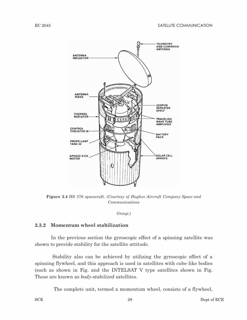
Figure 2.4 HS 376 spacecraft. (Courtesy of Hughes Aircraft Company Space andCommunications
Group.)
2.3.2 Momentum wheel stabilization
In the previous section the gyroscopic effect of a spinning satellite wasshown to provide stability for the satellite attitude.
Stability also can be achieved by utilizing the gyroscopic effect of aspinning flywheel, and this approach is used in satellites with cube-like bodies(such as shown in Fig. and the INTELSAT V type satellites shown in Fig.These are known as body-stabilized satellites.
The complete unit, termed a momentum wheel, consists of a flywheel,

EC 2045 SATELLITE COMMUNICATION
SCE 29 Dept of ECE
the bearing assembly, the casing, and an electric drive motor with associatedelectronic con- trol circuitry.
The flywheel is attached to the rotor, which consists of a permanentmagnet providing the magnetic field for motor action. The stator of the motor isattached to the body of the satellite.
Thus the motor provides the coupling between the flywheel and thesatellite structure. Speed and torque control of the motor is exercised throughthe currents fed to the stator.
.
Figure 2.5 Alternative momentum wheel stabilization systems: (a) one-wheel, (b) two- wheel,(c) three-wheel.
When a momentum wheel is operated with zero momentum bias, it isgenerally referred to as a reaction wheel. Reaction wheels are used in three-axis stabilized systems. Here, as the name suggests, each axis is stabilized by areaction wheel, as shown in Fig. 7.8c. Reaction wheels can also be combinedwith a momentum wheel to provide the control needed (Chetty, 1991).

EC 2045 SATELLITE COMMUNICATION
SCE 30 Dept of ECE
Random and cyclic disturbance torques tends to produce zeromomentum on average. However, there will always be some disturbancetorques that causes a cumulative increase in wheel momentum, and eventuallyat some point the wheel saturates.
In effect, it reaches its maximum allowable angular velocity and canno longer take in any more momentum. Mass expulsion devices are then usedto unload the wheel, that is, remove momentum from it (in the same way abrake removes energy from a moving vehicle). Of course, operation of the massexpulsion devices consumes part of the satellite’s fuel supply.
2.4 Thermal Control and Propulsion:
Satellites are subject to large thermal gradients, receiving the sun’sradiation on one side while the other side faces into space. In addition, thermalradiation from the earth and the earth’s albedo, which is the fraction of theradiation falling on earth which is reflected, can be sig- nificant for low-altitude earth-orbiting satellites, although it is negligi- ble for geostationarysatellites.
Equipment in the satellite also generates heat which has to beremoved. The most important consideration is that the satellite’s equipmentshould operate as nearly as possible in a stable temperature environment.Various steps are taken to achieve this. Thermal blankets and shields may beused to provide insulation. Radiation mirrors are often used to remove heatfrom the communications payload.
The mirrored thermal radiator for the Hughes HS 376 satellite canbe seen in Fig. These mirrored drums surround the communications equipmentshelves in each case and pro- vide good radiation paths for the generated heatto escape into the surrounding space.
One advantage of spinning satellites compared with body-stabilized is that the spinning body provides an averaging of the temperatureextremes experienced from solar flux and the cold back- ground of deep space.
In order to maintain constant temperature conditions, heaters may beswitched on (usually on command from ground) to make up for the heatreduction which occurs when transponders are switched off. The INTELSAT VIsatellite used heaters to maintain propulsion thrusters and line temperatures(Pilcher, 1982).

EC 2045 SATELLITE COMMUNICATION
SCE 31 Dept of ECE
2.5 Communication Payload & Supporting Subsystems:
The physical principle of establishing communication connectionsbetween remote communication devices dates back to the late 1800s whenscientists were beginning to understand electromagnetism and discovered thatelectromagnetic (EM) radiation (also called EM waves ) generated by onedevice can be detected by another located at some distance away.
By controlling certain aspect s of the radiation (through a process calledmodulation , explained in Section 4.4), useful information can be embedded inthe EM waves and transmitted from one device to another.
The second major module is the communication payload, which is made up oftransponders. A transponder is capable of :
Receiving uplinked radio signals from earth satellite transmissionstations (antennas).
Amplifying received radio signals Sorting the input signals and directing the output signals through
input/output signal multiplexers to the proper downlink antennas forretransmission to earth satellite receiving stations (antennas).
2.6 TT&C Subsystem
The TT&C subsystem performs several routine functions aboard thespacecraft. The telemetry, or telemetering, function could be interpreted asmeasurement at a distance. Specifically, it refers to the overall oper- ation ofgenerating an electrical signal proportional to the quantity being measuredand encoding and transmitting this to a distant station, which for the satellite isone of the earth stations.
Data which are trans- mitted as telemetry signals include attitudeinformation such as that obtained from sun and earth sensors; environmentalinformation such as the magnetic field intensity and direction, the frequency ofmeteorite impact, and so on; and spacecraft information such as temperatures,power supply voltages, and stored-fuel pressure.
Telemetry and command may be thought of as complementary func- tions.The telemetry subsystem transmits information about the satellite to the earthstation, while the command subsystem receives command sig- nals from the earthstation, often in response to telemetered information. The command subsystem

EC 2045 SATELLITE COMMUNICATION
SCE 32 Dept of ECE
demodulates and, if necessary, decodes the com- mand signals and routes these tothe appropriate equipment needed to exe- cute the necessary action.
Thus attitude changes may be made, communication transpondersswitched in and out of circuits, antennas redirected, and station-keepingmaneuvers carried out on command. It is clearly important to preventunauthorized commands from being received and decoded, and for this reason, thecommand signals are often encrypted.
Encrypt is derived from a Greek word kryptein, meaning to hide, and rep-resents the process of concealing the command signals in a secure code. Thisdiffers from the normal process of encoding which converts characters in thecommand signal into a code suitable for transmission.
Tracking of the satellite is accomplished by having the satellite trans-mit beacon signals which are received at the TT&C earth stations.
Tracking is obviously important during the transfer and drift orbitalphases of the satellite launch. Once it is on station, the position of a geo-stationary satellite will tend to be shifted as a result of the various dis- turbingforces, as described previously.
Therefore, it is necessary to be able to track the satellite’s movementand send correction signals as required.
2.6.1 Transponders:
A transponder is the series of interconnected units which forms a singlecommunications channel between the receive and transmit antennas in acommunications satellite.
Some of the units utilized by a transponder in a given channel may becommon to a number of transponders. Thus, although reference may be made to aspecific transponder, this must be thought of as an equipment channel ratherthan a single item of equipment.
Before describing in detail the various units of a transponder, theoverall frequency arrangement of a typical C-band communications satellitewill be examined briefly. The bandwidth allocated for C-band service is 500MHz, and this is divided into subbands, one transponder.

EC 2045 SATELLITE COMMUNICATION
SCE 33 Dept of ECE
A typical transponder bandwidth is 36 MHz, and allowing for a 4-MHzguardband between transponders, 12 such transponders can be accommodated inthe 500-MHz bandwidth.
Figure 2.8 Satellite control system. (Courtesy of Telesat Canada, 1983.)
By making use of polar- ization isolation, this number can be doubled.Polarization isolation refers to the fact that carriers, which may be on the samefrequency but with opposite senses of polarization, can be isolated from oneanother by receiving antennas matched to the incoming polarization.
With linear polarization, vertically and horizontally polarized carrierscan be sep- arated in this way, and with circular polarization, left-handcircular and right-hand circular polarizations can be separated.

EC 2045 SATELLITE COMMUNICATION
SCE 34 Dept of ECE
Because the carriers with opposite senses of polarization may overlapin frequency, this technique is referred to as frequency reuse. Figure 2.9 showspart of the frequency and polarization plan for a C-band communicationssatellite.
Figure 2.9 Section of an uplink frequency and polarization plan. Numbers refer to frequencyin megahertz.
Frequency reuse also may be achieved with spot-beam antennas, andthese may be combined with polarization reuse to provide an effectivebandwidth of 2000 MHz from the actual bandwidth of 500 MHz.

EC 2045 SATELLITE COMMUNICATION
SCE 35 Dept of ECE
For one of the polarization groups, Fig. 2.9 shows the channelingscheme for the 12 transponders in more detail. The incoming, or uplink,frequency range is 5.925 to 6.425 GHz.
The frequency conversion shifts the carriers to the downlinkfrequency band, which is also 500 MHz wide, extending from 3.7 to 4.2 GHz.At this point the signals are channelized into frequency bands whichrepresent the individual transponder bandwidths.
2.6.2 The wideband receiver
The wideband receiver is shown in more detail in Fig. 2.10. A duplicatereceiver is provided so that if one fails, the other is automatically switched in. Thecombination is referred to as a redundant receiver, meaning that although twoare provided, only one is in use at a given time.
The first stage in the receiver is a low-noise amplifier (LNA). Thisamplifier adds little noise to the carrier being amplified, and at the same timeit provides sufficient amplification for the carrier to override the higher noiselevel present in the following mixer stage.
Figure 2.10 Satellite transponder channels

EC 2045 SATELLITE COMMUNICATION
SCE 37 Dept of ECE
Figure 2.11 Satellite wideband receiver. (Courtesy of CCIR, CCIR Fixed Satellite ServicesHandbook, final draft 1984.)
involving noise, it is usually more convenient to refer all noise levels to the LNAinput, where the total receiver noise may be expressed in terms of an equivalentnoise temperature.
In a well-designed receiver, the equivalent noise temperaturereferred to the LNA input is basically that of the LNA alone. The overallnoise temperature must take into account the noise added from the antenna,and these calculations are presented in detail in Chap. 12. The equivalentnoise temperature of a satellite receiver may be on the order of a few hundredkelvins.
The LNA feeds into a mixer stage, which also requires a local oscil-lator (LO) signal for the frequency-conversion process.
With advances in field-effect transistor (FET) technology, FET amplifiers,which offer equal or better performance, are now available for both bands. Diodemixer stages are used.
The amplifier following the mixer may utilize bipolar junctiontransistors (BJTs) at 4 GHz and FETs at 12 GHz, or FETs may in fact be usedin both bands.

EC 2045 SATELLITE COMMUNICATION
SCE 38 Dept of ECE
2.6.3 The input demultiplexer
The input demultiplexer separates the broadband input, covering thefrequency range 3.7 to 4.2 GHz, into the transponder frequency channels.
This provides greater frequency separation between adjacent channelsin a group, which reduces adjacent channel interference.
The output from the receiver is fed to a power splitter, which in turnfeeds the two separate chains of circulators.
Figure 2.12 Satellite input multiplexer
The full broadband signal is transmitted along each chain, and thechannelizing is achieved by means of channel filters con- nected to eachcirculator,
Each filter has a bandwidth of 36 MHz and is tuned to theappropriate center frequency, as shown in Fig. 2.11.
Although there are considerable losses in the demultiplexer, these areeasily made up in the overall gain for the transponder channels.

EC 2045 SATELLITE COMMUNICATION
SCE 39 Dept of ECE
2.6.4 The power amplifier
The fixed attenuation is needed to balance out variations in the inputattenuation so that each transpon- der channel has the same nominalattenuation, the necessary adjust- ments being made during assembly.
The variable attenuation is needed to set the level as required fordifferent types of service (an example being the requirement for input powerbackoff discussed later). Because this variable attenuator adjustment is anoperational requirement, it must be under the control of the ground TT&Cstation.
Traveling-wave tube amplifiers (TWTAs) are widely used in transpon- dersto provide the final output power required to the transmit antenna. Figure 2.13shows the schematic of a traveling wave tube (TWT) and its power supplies.
In the TWT, an electron-beam gun assembly consisting of a heater, acathode, and focusing electrodes is used to form an elec- tron beam. A magneticfield is required to confine the beam to travel along the inside of a wire helix.
Figure 2.13 Satellite TWTA

EC 2045 SATELLITE COMMUNICATION
SCE 40 Dept of ECE
used in ground stations, the magnetic field can be provided by means of asolenoid and dc power supply. The comparatively large size and high powerconsumption of solenoids make them unsuitable for use aboard satellites, andlower-power TWTs are used which employ permanent- magnet focusing.
The wave actually will travel around the helical path at close to thespeed of light, but it is the axial component of wave velocity which interactswith the electron beam.
This component is less than the velocity of light approximately in theratio of helix pitch to circumference. Because of this effective reduction inphase velocity, the helix is referred to as a slowwave structure.
The advantage of the TWT over other types of tube amplifiers is that itcan provide amplification over a very wide bandwidth. Input levels to the TWTmust be carefully controlled, however, to minimize the effects of certain formsof distortion.
The worst of these result from the nonlinear transfer characteristic ofthe TWT, illustrated in Fig. 2.14.
Figure 2.14 Power transfer characteristics of a TWT. The saturation point is used as 0-dBreference for both input and output.

EC 2045 SATELLITE COMMUNICATION
SCE 41 Dept of ECE
At low-input powers, the output-input power relationship is linear;that is, a given decibel change in input power will produce the same decibelchange in output power. At higher power inputs, the output power sat- urates,the point of maximum power output being known as the satu- ration point.
The saturation point is a very convenient reference point, and inputand output quantities are usually referred to it. The linear region of the TWTis defined as the region bound by the thermal noise limit at the low end and bywhat is termed the 1-dB compression point at the upper end. This is the pointwhere the actual transfer curve drops
2.7. Satellite uplink and downlink Analysis and Design:
2.7.1 Introduction
This chapter describes how the link-power budget calculations are made.These calculations basically relate two quantities, the transmit power and thereceive power, and show in detail how the difference between these two powersis accounted for.
Link-budget calculations are usually made using decibel or decilogquantities. These are explained in App. G. In this text [square] brackets areused to denote decibel quantities using the basic power definition.
Where no ambiguity arises regarding the units, the abbreviation dB isused. For example, Boltzmann’s constant is given as 228.6 dB, although,strictly speaking, this should be given as 228.6 deci logs relative to 1 J/K.
2.7.2 Equivalent Isotropic Radiated Power
A key parameter in link-budget calculations is the equivalent isotropicradiated power, conventionally denoted as EIRP. From Eqs, the maximumpower flux density at some distance r from a transmitting antenna of gain G i
Pr=
An isotropic radiator with an input power equal to GPS would producethe same flux density. Hence, this product is referred to as the EIRP, or EIRP isoften expressed in decibels relative to 1 W, or dBW. Let PS be in watts; then[EIRP] = [PS] x [G] dB ,where [PS] is also in dBW and [G] is in dB.

EC 2045 SATELLITE COMMUNICATION
SCE 42 Dept of ECE
2.7.3 Transmission Losses
The [EIRP] may be thought of as the power input to one end of thetransmission link, and the problem is to find the power received at the other end.Losses will occur along the way, some of which are constant.
Other losses can only be estimated from statistical data, and some of these aredependent on weather conditions, especially on rainfall.
The first step in the calculations is to determine the losses for clear- weather orclear-sky conditions. These calculations take into account the losses, including thosecalculated on a statistical basis, which do not vary significantly with time. Losseswhich are weather-related, and other losses which fluctuate with time, are thenallowed for by introducing appropriate fade margins into the transmissionequation.
Free-space transmission:
As a first step in the loss calculations, the power loss resulting from thespreading of the signal in space must be determined.
Feeder losses:
Losses will occur in the connection between the receive antenna and thereceiver proper. Such losses will occur in the connecting waveguides, filters, andcouplers. These will be denoted by RFL, or [RFL] dB, for receiver feeder losses.
Antenna misalignment losses:
When a satellite link is established, the ideal situation is to have the earthstation and satellite antennas aligned for maximum gain, as shown in Fig. Thereare two possible sources of off-axis loss, one at the satellite and one at the earthstation, as shown in Fig.
The off-axis loss at the satellite is taken into account by designing the link foroperation on the actual satellite antenna contour; this is described in more detailin later sections. The off-axis loss at the earth station is referred to as the antennapointing loss. Antenna pointing losses are usually only a few tenths of a decibel;
In addition to pointing losses, losses may result at the antenna frommisalignment of the polarization direction (these are in addition to thepolarization losses described in Chap. 5). The polarization misalign- ment losses

EC 2045 SATELLITE COMMUNICATION
SCE 43 Dept of ECE
are usually small, and it will be assumed that the antenna misalignment losses,denoted by [AML], include both pointing and polar- ization losses resulting fromantenna misalignment. It should be noted
Figure 2.15 (a) Satellite and earth-station antennas aligned for maximum gain; (b) earth stationsituated on a given satellite “footprint,” and earth-station antenna misaligned.
2.8 The Link-Power Budget Equation:
Now that the losses for the link have been identified, the power at thereceiver, which is the power output of the link, may be calculated simply as[EIRP] [LOSSES] [GR], where the last quantity is the receiver antenna gain.Note carefully that decibel addition must be used.
The major source of loss in any ground-satellite link is the free-spacespreading loss [FSL], the basic link-power budget equation taking into accountthis loss only. However, the other losses also must be taken into account, and theseare simply added to [FSL]. The losses for clear-sky conditions are
[LOSSES] = [FSL] + [RFL] + [AML] + [AA] - [PL] equation for thereceived power is then
[PR] = [EIRP] x [GR] - [LOSSES]
where [PR] received power, dBW

EC 2045 SATELLITE COMMUNICATION
SCE 44 Dept of ECE
[EIRP] equivalent isotropic radiated power, dBW [FSL] free-spacespreading loss, dB
[RFL] receiver feeder loss, dB
[AML] antenna misalignment loss, dB
[AA] atmospheric absorption loss, dB [PL] polarization mismatch loss,dB
2.9 Amplifier noise temperature
Consider first the noise representation of the antenna and the low noiseamplifier (LNA) shown in Fig. 2.15.
The available power gain of the amplifier is denoted as G, and the noisepower output, as Pno.
Figure 2.15 LNA Amplifier gain
For the moment we will work with the noise power per unit bandwidth,which is simply noise energy in joules as shown by Eq.
The input noise energy coming from the antenna is
N0,ant = kTant

EC 2045 SATELLITE COMMUNICATION
SCE 45 Dept of ECE
2.10 The Uplink
The uplink of a satellite circuit is the one in which the earth station istransmitting the signal and the satellite is receiving it specifically that the uplinkis being considered.
= [ ] − [ ] + [ ]In this Eq the values to be used are the earth station EIRP, the satellite
receiver feeder losses, and satellite receiver G/T. The free-space loss and otherlosses which are frequency-dependent are calculated for the uplink frequency.
2.10.1 Input backoff
Number of carriers are present simultaneously in a TWTA, the operatingpoint must be backed off to a linear portion of the transfer characteristic to reducethe effects of inter modulation distortion. Such multiple carrier operation occurswith frequency- division multiple access (FDMA), which is described in Chap. 14.The point to be made here is that backoff (BO) must be allowed for in the link- budgetcalculations.
Suppose that the saturation flux density for single-carrier operation is known.Input BO will be specified for multiple-carrier operation, referred to the single-carrier saturation level. The earth-station EIRP will have to be reduced by thespecified BO, resulting in an uplink value of
[EIRP]U = [EIRPS]U + [BO]i
2.10.2 The earth station HPA
The earth station HPA has to supply the radiated power plus the transmitfeeder losses, denoted here by TFL, or [TFL] dB. These include waveguide, filter, andcoupler losses between the HPA output and the transmit antenna. Referring back to Eq.(12.3), the power output of
The earth station itself may have to transmit multiple carriers, and itsoutput also will require back off, denoted by [BO]HPA. The earth station HPAmust be rated for a saturation power output given by
[PHPA,sat] = [PHPA] + [BO]HPA

EC 2045 SATELLITE COMMUNICATION
SCE 46 Dept of ECE
N
2.11 Downlink
The downlink of a satellite circuit is the one in which the satellite is trans-mitting the signal and the earth station is receiving it. Equation can be applied to thedownlink, but subscript D will be used to denote specifically that the downlink isbeing considered. Thus Eq. becomes= [ ] − [ ] + [ ]
In Eq. the values to be used are the satellite EIRP, the earth- stationreceiver feeder losses, and the earth-station receiver G/T. The free space and otherlosses are calculated for the downlink frequency. The resulting carrier-to-noisedensity ratio given by Eq. is that which appears at the detector of the earthstation receiver.
2.11.1 Output back-off
Where input BO is employed as described in a corresponding output BO mustbe allowed for in the satellite EIRP. As the curve of Fig. 2.16 shows, output BO isnot linearly related to input BO. A rule of thumb, frequently used, is to take theoutput BO as the point on the curve which is 5 dB below the extrapolated linearportion, as shown in Fig. 12.7. Since the linear portion gives a 1:1 change indecibels, the relationship between input and output BO is [BO]0 [BO]i 5 dB.For example, with an input BO of [BO]i 11 dB, the corresponding output BO is[BO]0
Figure 2.16 Input and output back-off relationship for the satellitetraveling-wave-tube amplifier; [BO]i[BO]0 5 dB.

EC 2045 SATELLITE COMMUNICATION
SCE 47 Dept of ECE
2.11.2 Effects of Rain
In the C band and, more especially, the Ku band, rainfall is the mostsignificant cause of signal fading. Rainfall results in attenuation of radio waves byscattering and by absorption of energy from the wave.
Rain attenuation increases with increasing frequency and is worse in the Kuband compared with the C band.
This produces a depolarization of the wave; in effect, the wave becomes ellipti-cally polarized. This is true for both linear and circular polar- izations, and the effectseems to be much worse for circular polarization (Freeman, 1981).
The C/N0 ratio for the downlink alone, not counting the PNU contri- bution, isPR/PND, and the combined C/N0 ratio at the ground receiver is
Figure 2.17 (a) Combined uplink and downlink; (b) power flow diagram
The reason for this reciprocal of the sum of the reciprocals method is that asingle signal power is being transferred through the system, while the variousnoise powers, which are present are additive. Similar reasoning applies to thecarrier-to-noise ratio, C/N.

EC 2045 SATELLITE COMMUNICATION
SCE 48 Dept of ECE
2.12. inter modulation and interference:
Intermodulation interference is the undesired combining of several signalsin a nonlinear device, producing new, unwanted frequencies, which can causeinterference in adjacent receivers located at repeater sites.
Not all interference is a result of intermodulation distortion. It can comefrom co-channel interference, atmospheric conditions as well as man-made noisegenerated by medical, welding and heating equipment.
Most intermodulation occurs in a transmitter's nonlinear power amplifier(PA). The next most common mixing point is in the front end of a receiver. Usuallyit occurs in the unprotected first mixer of older model radios or in some cases anoverdriven RF front-end amp.
Intermodulation can also be produced in rusty or corroded tower joints, guywires, turnbuckles and anchor rods or any nearby metallic object, which can act asa nonlinear "mixer/rectifier" device.
2.13. Propagation Characteristics and Frequency considerations:
2.13.1 Introduction
A number of factors resulting from changes in the atmosphere have to betaken into account when designing a satellite communications system in order toavoid impairment of the wanted signal.
Generally, a margin in the required carrier-to-noise ratio is incorporated toaccommodate such effects.
2.13.2 Radio Noise
Radio noise emitted by matter is used as a source of information inradioastronomy and in remote sensing. Noise of a thermal origin has a continuousspectrum, but several other radiation mechanisms cause the emission to have aspectral-line structure. Atoms and molecules are distinguished by their differentspectral lines.
For other services such as satellite communications noise is a limitingfactor for the receiving system; generally, it is inappropriate to use receivingsystems with noise temperatures which are much less than those specified by theminimum external noise.

EC 2045 SATELLITE COMMUNICATION
SCE 49 Dept of ECE
From about 30 MHz to about 1 GHz cosmic noise predominates overatmospheric noise except during local thunderstorms, but will generally beexceeded by man-made noise in populated areas.
In the bands of strong gaseous absorption, the noise temperature reachesmaximum values of some 290 K. At times, precipitation will also increase thenoise temperature at frequencies above 5 GHz.
Figure 6.1 gives an indication of sky noise at various elevation angles andfrequencies.
Figure 2.18 Sky-Noise Temperature for Clear Air
2.14. System reliability and design lifetime:
2.14.1 System reliability:
Satellites are designed to operate dependably throughout theiroperational life, usually a number of years.
This is achieved through stringent quality control and testing of parts andsubsystems before they are used in the construction of the satellite.
Redundancy of key components is often built in so that if a particular partor subassembly fails, another can perform its functions.
In addition, hardware and software on the satellite are often designed sothat ground controllers can reconfigure the satellite to work around a part thathas failed.

EC 2045 SATELLITE COMMUNICATION
SCE 50 Dept of ECE
2.14.2. Design lifetime:
The Milstar constellation has demonstrated exceptional reliability andcapability, providing vital protected communications to the warfighter,” saidKevin Bilger, vice president and general manager, Global CommunicationsSystems, Lockheed Martin Space Systems in Sunnyvale.
“Milstar’s robust system offers our nation worldwide connectivity withflexible, dependable and highly secure satellite communications.”
The five-satellite Milstar constellation has surpassed 63 years of combinedsuccessful operations, and provides a protected, global communication network forthe joint forces of the U.S. military. In addition, it can transmit voice, data, andimagery, and offers video teleconferencing capabilities.
The system is the principal survivable, endurable communicationsstructure that the President, the Secretary of Defense and the Commander, U.S.Strategic Command use to maintain positive command and control of the nation'sstrategic forces.
In addition to this 10-year milestone for Flight-5, each of the first twoMilstar satellites have been on orbit for over 16 years – far exceeding their 10-yeardesign life.
The next-generation Lockheed Martin-built Advanced EHF satellites,joining the Milstar constellation, provide five times faster data rates and twice asmany connections, permitting transmission of strategic and tactical militarycommunications, such as real-time video, battlefield maps and targetingdata. Advanced EHF satellites are designed to be fully interoperable andbackward compatible with Milstar.
Headquartered in Bethesda, Md., Lockheed Martin is a global securitycompany that employs about 123,000 people worldwide and is principally engagedin the research, design, development, manufacture, integration and sustainmentof advanced technology systems, products and services. The Corporation's netsales for 2011 were $46.5 billion.

EC 2045 SATELLITE COMMUNICATION
SCE 51 Dept of ECE
UNIT III SATELLITE ACCESS
3.1 Modulation and Multiplexing: Voice, Data, Video :
Communications satellites are used to carry telephone, video, and datasignals, and can use both analog and digital modulation techniques.
Modulation:Modification of a carrier’s parameters (amplitude, frequency, phase, or a
combination of them) in dependence on the symbol to be sent.Multiplexing:
Task of multiplexing is to assign space, time, frequency, and code to eachcommunication channel with a minimum of interference and a maximum ofmedium utilization Communication channel refers to an association of sender(s)and receiver(s) that want to exchange data One of several constellations of acarrier’s parameters defined by the used modulation scheme.
3.1.1 Voice, Data, Video :The modulation and multiplexing techniques that were used at this time
were analog, adapted from the technology developed for The change to digitalvoice signals made it easier for long-distance.
Figure 3.1 Modulation and Multiplexing: Voice/Data/Video

EC 2045 SATELLITE COMMUNICATION
SCE 52 Dept of ECE
Communication carriers to mix digital data and telephone Fiber-opticCable Transmission Standards System Bit rate (Mbps) 64- kbps Voice channelcapacity Stuffing bits and words are added to the satellite data stream as neededto fill empty bit and word spaces.
Primarily for video provided that a satellite link's overall carrier-to-noisebut in to older receiving equipment at System and Satellite Specification Ku-band satellite parameters.
3.1.2 Modulation And Multiplexing:
In analog television (TV) transmission by satellite, the baseband videosignal and one or two audio subcarriers constitute a composite video signal.
Digital modulation is obviously the modulation of choice for transmittingdigital data are digitized analog signals may conveniently share a channel withdigital data, allowing a link to carry a varying mix of voice and data traffic.
Digital signals from different channels are interleaved for transmissionthrough time division multiplexing TDM carry any type of traffic — the bentpipe transponder that can carry voice, video, or data as the marketplacedemands.
Hybrid multiple access schemes can use time division multiplexing ofbaseband channels which are then modulate.
3.2 Analog – digital transmission system :
3.2.1 Analog vs. Digital Transmission:
Compare at two levels:
1. Data—continuous (audio) vs. discrete (text)2. Signaling—continuously varying electromagnetic wave vs. sequence of
voltage pulses.
Also Transmission—transmit without regard to signal content vs. beingconcerned with signal content. Difference in how attenuation is handled, but notfocus on this.Seeing a shift towards digital transmission despite large analogbase. Why?

EC 2045 SATELLITE COMMUNICATION
SCE 53 Dept of ECE
Figure 3.2 basic communication systems
• Improving digital technology• Data integrity. Repeaters take out cumulative problems in transmission.
Can thus transmit longer distances.• Easier to multiplex large channel capacities with digital• Easy to apply encryption to digital data• Better integration if all signals are in one form. Can integrate voice, video
and digital data.
3.2.2 Digital Data/Analog Signals:
Must convert digital data to analog signal such device is a modem totranslate between bit-serial and modulated carrier signals?
To send digital data using analog technology, the sender generates acarrier signal at some continuous tone (e.g. 1-2 kHz in phone circuits) that lookslike a sine wave. The following techniques are used to encode digital data intoanalog signals.
Figure 3.3 Digital /Analog Transmitter & receiver

EC 2045 SATELLITE COMMUNICATION
SCE 54 Dept of ECE
Resulting bandwidth is centered on the carrier frequency.
• Amplitude-shift modulation (keying): vary the amplitude (e.g. voltage) ofthe signal. Used to transmit digital data over optical fiber.
• Frequency-shift modulation: two (or more tones) are used, which are nearthe carrier frequency. Used in a full-duplex modem (signals in bothdirections).
• Phase-shift modulation: systematically shift the carrier wave at uniformlyspaced intervals.
For instance, the wave could be shifted by 45, 135, 225, 315 degree at eachtiming mark. In this case, each timing interval carries 2 bits of information.
Why not shift by 0, 90, 180, 270? Shifting zero degrees means no shift, andan extended set of no shifts leads to clock synchronization difficulties.
Frequency division multiplexing (FDM): Divide the frequencyspectrum into smaller subchannels, giving each user exclusive use of asubchannel (e.g., radio and TV). One problem with FDM is that a user is givenall of the frequency to use, and if the user has no data to send, bandwidth iswasted — it cannot be used by another user.
Time division multiplexing (TDM): Use time slicing to give each userthe full bandwidth, but for only a fraction of a second at a time (analogous totime sharing in operating systems). Again, if the user doesn’t have data to sentduring his timeslice, the bandwidth is not used (e.g., wasted).
Statistical multiplexing: Allocate bandwidth to arriving packets ondemand. This leads to the most efficient use of channel bandwidth because itonly carries useful data.That is, channel bandwidth is allocated to packets thatare waiting for transmission, and a user generating no packets doesn’t use any ofthe channel resources.
3.3. Digital Video Broadcasting (DVB):
Digital Video Broadcasting (DVB) has become the synonym for digitaltelevision and for data broadcasting world-wide.
DVB services have recently been introduced in Europe, in North- andSouth America, in Asia, Africa and Australia.

EC 2045 SATELLITE COMMUNICATION
SCE 55 Dept of ECE
This article aims at describing what DVB is all about and at introducingsome of the technical background of a technology that makes possible thebroadcasting.
Figure 3.4 Digital Video Broadcasting systems
3.4 Multiple Access Techniques:
The transmission from the BS in the downlink can be heard by each andevery mobile user in the cell, and is referred as broadcasting.Transmission from the mobile users in the uplink to the BS is many-to-one, and is referred to as multiple access.
Multiple access schemes to allow many users to share simultaneously afinite amount of radio spectrum resources.
Should not result in severe degradation in the performance of thesystem as compared to a single user scenario.
Approaches can be broadly grouped into two categories: narrowbandand wideband.
Multiple Accessing Techniques : with possible conflict and conflict- free

EC 2045 SATELLITE COMMUNICATION
SCE 56 Dept of ECE
Random access Frequency division multiple access (FDMA) Time division multiple access (TDMA) Spread spectrum multiple access (SSMA) : an example is Code
division multiple access (CDMA) Space division multiple access (SDMA)
Duplexing:
For voice or data communications, must assure two way communication(duplexing, it is possible to talk and listen simultaneously). Duplexingmay be done using frequency or time domain techniques. Forward (downlink) band provides traffic from the BS to the mobile Reverse (uplink) band provides traffic from the mobile to the BS.
3.4.1 Frequency division duplexing (FDD):
Provides two distinct bands of frequencies for every user, one for downlinkand one for uplink.
A large interval between these frequency bands must be allowed so thatinterference is minimized.
Figure 3.5 Frequency Separation
3.4.2. Time division duplexing (TDD):
In TDD communications, both directions of transmission use onecontiguous frequency allocation, but two separate time slots to provideboth a forward and reverse link.

EC 2045 SATELLITE COMMUNICATION
SCE 57 Dept of ECE
Because transmission from mobile to BS and from BS to mobile alternatesin time, this scheme is also known as “ping pong”.
As a consequence of the use of the same frequency band, thecommunication quality in both directions is the same. This is differentfrom FDD.
Figure 3.6 Time Slot3.4.3 FDMA:
In FDMA, each user is allocated a unique frequency band or channel.During the period of the call, no other user can share the same frequencyband.
Figure 3.7 FDMA Channels
All channels in a cell are available to all the mobiles. Channel assignmentis carried out on a first-come first- served basis.

EC 2045 SATELLITE COMMUNICATION
SCE 58 Dept of ECE
The number of channels, given a frequency spectrum BT , depends on themodulation technique (hence Bw or Bc ) and the guard bands between thechannels 2Bguard .
These guard bands allow for imperfect filters and oscillators and can beused to minimize adjacent channel interference.
FDMA is usually implemented in narrowband systems.
Figure 3.8 FDMA/FDD/TDD
Nonlinear effects in FDMA:
In a FDMA system, many channels share the same antenna at theBS. The power amplifiers or the power combiners, when operatedat or near saturation are nonlinear.
The nonlinear ties generate inter-modulation frequencies.
Undesirable harmonics generated outside the mobile radio bandcause interference to adjacent services.
Undesirable harmonics present inside the band cause interferenceto other users in the mobile system.

EC 2045 SATELLITE COMMUNICATION
SCE 59 Dept of ECE
3.4.4 TDMA:
TDMA systems divide the channel time into frames. Each frame is furtherpartitioned into time slots. In each slot only one user is allowed to eithertransmit or receive.
Unlike FDMA, only digital data and digital modulation must be used.
Each user occupies a cyclically repeating time slot, so a channel may bethought of as a particular time slot of every frame, where N time slotscomprise a frame.
Figure 3.9 TDMA Channels
Features:
Multiple channels per carrier or RF channels.
Burst transmission since channels are used on a timesharing basis.Transmitter can be turned off during idle periods.
Narrow or wide bandwidth – depends on factors such as modulationscheme, number of voice channels per carrier channel.
High ISI – Higher transmission symbol rate, hence resulting in high ISI.Adaptive equalizer required.

EC 2045 SATELLITE COMMUNICATION
SCE 60 Dept of ECE
Figure 3.10 TDMA Channels time slot
A guard time between the two time slots must be allowed in order to avoidinterference, especially in the uplink direction. All mobiles shouldsynchronize with BS to minimize interference.
Efficient power utilization : FDMA systems require a 3- to 6-dB power backoff in order to compensate for inter-modulation effects.
Efficient handoff : TDMA systems can take advantage of the fact that thetransmitter is switched off during idle time slots to improve the handoffprocedure. An enhanced link control, such as that provided by mobileassisted handoff (MAHO) can be carried out by a subscriber by listening toneighboring base station during the idle slot of the TDMA frame.
Efficiency of TDMA
Efficiency of TDMA is a measure of the percentage of bits per frame whichcontain transmitted data. The transmitted data include source and channelcoding bits.
bOH includes all overhead bits such as preamble, guard bits, etc.

EC 2045 SATELLITE COMMUNICATION
SCE 61 Dept of ECE
3.4.5 Code Division Multiple Access (CDMA):
Spreading signal (code) consists of chips
Has Chip period and and hence, chip rate
Spreading signal use a pseudo-noise (PN) sequence (a pseudo-randomsequence)
PN sequence is called a codeword
Each user has its own cordword
Codewords are orthogonal. (low autocorrelation)
Chip rate is oder of magnitude larger than the symbol rate.
The receiver correlator distinguishes the senders signal by examining thewideband signal with the same time-synchronized spreading code
The sent signal is recovered by despreading process at the receiver.
CDMA Advantages:
Low power spectral density.
Signal is spread over a larger frequency band
Other systems suffer less from the transmitter
Interference limited operation
All frequency spectrum is used
Privacy
The codeword is known only between the sender and receiver. Henceother users can not decode the messages that are in transit
Reduction of multipath affects by using a larger spectrum

EC 2045 SATELLITE COMMUNICATION
SCE 62 Dept of ECE
CDMA data:
Figure 3.11 CDMA Channels transmission
DSSS Transmitter:
EC 2045 SATELLITE COMMUNICATION
SCE 62 Dept of ECE
CDMA data:
Figure 3.11 CDMA Channels transmission
DSSS Transmitter:
EC 2045 SATELLITE COMMUNICATION
SCE 62 Dept of ECE
CDMA data:
Figure 3.11 CDMA Channels transmission
DSSS Transmitter:

EC 2045 SATELLITE COMMUNICATION
SCE 63 Dept of ECE
Figure 3.12 CDMA Transmitter
DSSS Receiver
Figure 3.13 CDMA Receiver
FDMA/CDMA
Available wideband spectrum is frequency divided into numbernarrowband radio channels. CDMA is employed inside each channel.
DS/FHMA
The signals are spread using spreading codes (direct sequence signalsare obtained), but these signal are not transmitted over a constantcarrier frequency; they are transmitted over a frequency hoppingcarrier frequency.
Time Division CDMA (TCDMA)
Each cell is using a different spreading code (CDMA employedbetween cells) that is conveyed to the mobiles in its range.
Inside each cell (inside a CDMA channel), TDMA is employed tomultiplex multiple users.

EC 2045 SATELLITE COMMUNICATION
SCE 64 Dept of ECE
Time Division Frequency Hopping
At each time slot, the user is hopped to a new frequency according toa pseudo-random hopping sequence.
Employed in severe co-interference and multi-path environments.
Bluetooth and GSM are using this technique
A large number of independently steered high-gain beams can be formedwithout any resulting degradation in SNR ratio.
Beams can be assigned to individual users, thereby assuring that all linksoperate with maximum gain.
Adaptive beam forming can be easily implemented to improve the systemcapacity by suppressing co channel interference.
Advantage of CDMA
It is recognized that CDMA’s capacity gains over TDMA
FDMA are entirely due to Its tighter, dynamic control over the use of the powerdomain.
Choosing a new non-orthogonal PN sequence a CDMA system does not encounterthe difficulties of choosing a spare carrier frequency or time slot to carry a TrafficChannel
Ensure that interference will not be too great if it begins to transmit -that there isstill enough space left in the power domain.
Disadvantages of CDMA:
Satellite transponders are channelized too narrowly for roadband CDMA, which isthe most attractive form of CDMA.
Power control cannot be as tight as it is in a terrestrial system because of longround-trip delay.
3.5. Channel allocation schemes:
In radio resource management for wireless and cellular network, channelallocation schemes are required to allocate bandwidth and communicationchannels to base stations, access points and terminal equipment.

EC 2045 SATELLITE COMMUNICATION
SCE 65 Dept of ECE
The objective is to achieve maximum system spectral efficiency in bit/s/Hz/siteby means of frequency reuse, but still assure a certain grade of service by avoidingco-channel interference and adjacent channel interference among nearby cells ornetworks that share the bandwidth. There are two types of strategies that arefollowed:-
Fixed: FCA, fixed channel allocation: Manually assigned by the networkoperator
Dynamic:
DCA, dynamic channel allocation, DFS, dynamic frequency selection Spread spectrum
3.5.1 FCA:
In Fixed Channel Allocation or Fixed Channel Assignment (FCA)each cell is given a predetermined set of frequency channels.
FCA requires manual frequency planning, which is an arduous task inTDMA and FDMA based systems, since such systems are highly sensitive to co-channel interference from nearby cells that are reusing the same channel.
This results in traffic congestion and some calls being lost when traffic getsheavy in some cells, and idle capacity in other cells.
3.5.2. DCA and DFS:
Dynamic Frequency Selection (DFS) may be applied in wirelessnetworks with several adjacent non-centrally controlled access points.
A more efficient way of channel allocation would be Dynamic ChannelAllocation or Dynamic Channel Assignment (DCA) in which voice channel arenot allocated to cell permanently, instead for every call request base stationrequest channel from MSC.
3.6 Spread spectrum:
Spread spectrum can be considered as an alternative to complex DCAalgorithms. Spread spectrum avoids cochannel interference between adjacent

EC 2045 SATELLITE COMMUNICATION
SCE 66 Dept of ECE
cells, since the probability that users in nearby cells use the same spreading codeis insignificant.
Thus the frequency channel allocation problem is relaxed in cellularnetworks based on a combination of Spread spectrum and FDMA, for exampleIS95 and 3G systems.
In packet based data communication services, the communication is burstyand the traffic load rapidly changing. For high system spectrum efficiency, DCAshould be performed on a packet-by-packet basis.
Examples of algorithms for packet-by-packet DCA are Dynamic PacketAssignment (DPA), Dynamic Single Frequency Networks (DSFN) and Packetand resource plan scheduling (PARPS).
3.6.1 Spread spectrum Techniques:
1 In telecommunication and radio communication, spread-spectrumtechniques are methods by which a signal (e.g. an electrical, electromagnetic,or acoustic signal) generated with a particular bandwidth is deliberatelyspread in the frequency domain, resulting in a signal with a wider bandwidth.
2 These techniques are used for a variety of reasons, including theestablishment of secure communications, increasing resistance to naturalinterference, noise and jamming, to prevent detection, and to limit power fluxdensity (e.g. in satellite downlinks).
3 Spread-spectrum telecommunications this is a technique in which atelecommunication signal is transmitted on a bandwidth considerably largerthan the frequency content of the original information.
4 Spread-spectrum telecommunications is a signal structuringtechnique that employs direct sequence, frequency hopping, or a hybrid ofthese, which can be used for multiple access and/or multiple functions.
5 Frequency-hopping spread spectrum (FHSS), direct-sequence spreadspectrum (DSSS), time-hopping spread spectrum (THSS), chirp spreadspectrum (CSS).
6 Techniques known since the 1940s and used in militarycommunication systems since the 1950s "spread" a radio signal over a widefrequency range several magnitudes higher than minimum requirement.
7 Resistance to jamming (interference). DS (direct sequence) is good atresisting continuous-time narrowband jamming, while FH (frequency hopping)is better at resisting pulse jamming.
8 Resistance to fading. The high bandwidth occupied by spread-spectrum signals offer some frequency diversity, i.e. it is unlikely that the

EC 2045 SATELLITE COMMUNICATION
SCE 67 Dept of ECE
signal will encounter severe multipath fading over its whole bandwidth, andin other cases the signal can be detected using e.g. a Rake receiver.
9 Multiple access capability, known as code-division multiple access(CDMA) or code-division multiplexing (CDM). Multiple users can transmitsimultaneously in the same frequency band as long as they use differentspreading codes.
3.7 Compression – Encryption:
At the broadcast center, the high-quality digital stream of video goesthrough an MPEG encoder, which converts the programming to MPEG-4 video ofthe correct size and format for the satellite receiver in your house.
Encoding works in conjunction with compression to analyze each videoframe and eliminate redundant or irrelevant data and extrapolate informationfrom other frames. This process reduces the overall size of the file. Each frame canbe encoded in one of three ways:
As an intraframe, which contains the complete image data for that frame.This method provides the least compression.
As a predicted frame, which contains just enough information to tell thesatellite receiver how to display the frame based on the most recentlydisplayed intraframe or predicted frame.
As a bidirectional frame, which displays information from thesurrounding intraframe or predicted frames. Using data from the closestsurrounding frames, the receiver interpolates the position and color ofeach pixel.
This process occasionally produces artifacts -- glitches in the video image.One artifact is macroblocking, in which the fluid picture temporarily dissolvesinto blocks. Macroblocking is often mistakenly called pixilating, a technicallyincorrect term which has been accepted as slang for this annoying artifact.
There really are pixels on your TV screen, but they're too small for yourhuman eye to perceive them individually -- they're tiny squares of video data thatmake up the image you see. (For more information about pixels and perception,see How TV Works.)
The rate of compression depends on the nature of the programming. If theencoder is converting a newscast, it can use a lot more predicted frames becausemost of the scene stays the same from one frame to the next.

EC 2045 SATELLITE COMMUNICATION
SCE 68 Dept of ECE
In more fast-paced programming, things change very quickly from oneframe to the next, so the encoder has to create more intraframes. As a result, anewscast generally compresses to a smaller size than something like a car race.
3.7.1 Encryption and Transmission:
After the video is compressed, the provider encrypts it to keep people fromaccessing it for free. Encryption scrambles the digital data in such a way that itcan only be decrypted (converted back into usable data) if the receiver has thecorrect decryption algorithm and security keys.
Once the signal is compressed and encrypted, the broadcast center beams itdirectly to one of its satellites. The satellite picks up the signal with an onboarddish, amplifies the signal and uses another dish to beam the signal back to Earth,where viewers can pick it up.
In the next section, we'll see what happens when the signal reaches a viewer'shouse.
3.7.2 Video and Audio Compression:
Video and Audio files are very large beasts. Unless we develop andmaintain very high bandwidth networks (Gigabytes per second or more) we haveto compress to data.
Relying on higher bandwidths is not a good option -- M25 Syndrome: Trafficneeds ever increases and will adapt to swamp current limit whatever this is.
As we will compression becomes part of the representation or codingscheme which have become popular audio, image and video formats.
We will first study basic compression algorithms and then go on to studysome actual coding formats.

EC 2045 SATELLITE COMMUNICATION
SCE 69 Dept of ECE
Figure 3.14 coding scheme
What is Compression?Compression basically employs redundancy in the data:
Temporal -- in 1D data, 1D signals, Audio etc. Spatial -- correlation between neighbouring pixels or data items Spectral -- correlation between colour or luminescence components. This uses the
frequency domain to exploit relationships between frequency of change in data. psycho-visual -- exploit perceptual properties of the human visual system.
Compression can be categorised in two broad ways:
Lossless Compression :
-- where data is compressed and can be reconstituted (uncompressed) without lossof detail or information. These are referred to as bit-preserving or reversiblecompression systems also.
Lossy Compression :
-- where the aim is to obtain the best possible fidelity for a given bit-rate orminimizing the bit-rate to achieve a given fidelity measure. Video and audiocompression techniques are most suited to this form of compression.
If an image is compressed it clearly needs to uncompressed (decoded) beforeit can viewed/listened to. Some processing of data may be possible in encoded formhowever. Lossless compression frequently involves some form of entropy encodingand are based in information theoretic techniques.
Lossy compression use source encoding techniques that may involvetransform encoding, differential encoding or vector quantization.

EC 2045 SATELLITE COMMUNICATION
SCE 70 Dept of ECE
3.7.3 MPEG Standards :
All MPEG standards exist to promote system interoperability among yourcomputer, television and handheld video and audio devices. They are:
MPEG-1: the original standard for encoding and decoding streaming videoand audio files.
MPEG-2: the standard for digital television, this compresses files fortransmission of high-quality video.
MPEG-4: the standard for compressing high-definition video into smaller-scale files that stream to computers, cell phones and PDAs (personal digitalassistants).
MPEG-21: also referred to as the Multimedia Framework. The standardthat interprets what digital content to provide to which individual user sothat media plays flawlessly under any language, machine or userconditions.
Figure 3.15 MPEG scheme

EC 2045 SATELLITE COMMUNICATION
SCE 71 Dept of ECE
3.8 Encryption:
It is the most effective way to achieve data security. To read an encryptedfile, you must have access to a secret key or password that enables you to decryptit. Unencrypted data is called plain text ; encrypted data is referred to ascipher text.
Figure 3.16 Encryption methods
9.1.1 Symmetric key encryption:
In symmetric-key schemes, the encryption and decryption keys are thesame. Thus communicating parties must have the same key before they canachieve secret communication.
In public-key encryption schemes, the encryption key is published foranyone to use and encrypt messages. However, only the receiving party has accessto the decryption key that enables messages to be read.

EC 2045 SATELLITE COMMUNICATION
SCE 72 Dept of ECE
Figure 3.16 General block diagram Encryption methods
Decryption:
It is the process of taking encoded or encrypted text or other data andconverting it back into text that you or the computer are able to read andunderstand.
This term could be used to describe a method of un-encrypting the datamanually or with un-encrypting the data using the proper codes or keys.
Data may be encrypted to make it difficult for someone to steal theinformation. Some companies also encrypt data for general protection of companydata and trade secrets. If this data needs to be viewable, it may require decryption.

EC 2045 SATELLITE COMMUNICATION
SCE 73 Dept of ECE
UNIT IV EARTH SEGMENT
4.1 Earth Station Technology:
The earth segment of a satellite communications system consists of thetransmit and receive earth stations. The simplest of these are the home TVreceive-only (TVRO) systems, and the most complex are the terminal stations usedfor international communications networks. Also included in the earth segmentare those stations which are on ships at sea, and commercial and military landand aeronautical mobile stations.As mentioned in earth stations that are used for logistic sup- port of satellites, suchas providing the telemetry, tracking, and command (TT&C) functions, are consideredas part of the space segment.
4.1.1 Terrestrial Interface:
Earth station is a vital element in any satellite communication network.The function of an earth station is to receive information from or transmitinformation to, the satellite network in the most cost-effective and reliablemanner while retaining the desired signal quality. The design of earth stationconfiguration depends upon many factors and its location. But it isfundamentally governed by its
Location which are listed below,• In land• On a ship at sea• Onboard aircraft
The factors are• Type of services• Frequency bands used• Function of the transmitter• Function of the receiver• Antenna characteristics
4.1.2 Transmitter and Receiver
Any earth station consists of four major subsystems• Transmitter• Receiver• Antenna • Tracking equipment

EC 2045 SATELLITE COMMUNICATION
SCE 74 Dept of ECE
Two other important subsystems are• Terrestrial interface equipment• Power supply
The earth station depends on the following parameters• Transmitter power• Choice of frequency• Gain of antenna• Antenna efficiency• Antenna pointing accuracy• Noise temperature
The functional elements of a basic digital earth station are shown in the belowfigure
Figure 4.1 Transmitter- Receiver
Digital information in the form of binary digits from terrestrial networksenters earth station and is then processed (filtered, multiplexed, formatted etc.)by the base band equipment.
• The encoder performs error correction coding to reduce the error rate, byintroducing extra digits into digital stream generated by the base band

EC 2045 SATELLITE COMMUNICATION
SCE 75 Dept of ECE
equipment. The extra digits carry information.• In satellite communication, I.F carrier frequency is chosen at 70 MHz for
communication using a 36 MHz transponder bandwidth and at 140 MHz for atransponder bandwidth of 54 or 72 MHz.
• On the receive side, the earth station antenna receives the low-levelmodulated R.F carrier in the downlink frequency spectrum.
• The low noise amplifier (LNA) is used to amplify the weak receivedsignals and improve the signal to Noise ratio (SNR). The error rate requirementscan be met more easily.
• R.F is to be reconverted to I.F at 70 or 140 MHz because it is easierdesign a demodulation to work at these frequencies than 4 or 12 GHz.
• The demodulator estimate which of the possible symbols wastransmitted based on observation of the received if carrier.
• The decoder performs a function opposite that of the encoder. Becausethe sequence of symbols recovered by the demodulator may contain errors, thedecoder must use the uniqueness of the redundant digits introduced by theencoder to correct the errors and recover information-bearing digits.
• The information stream is fed to the base-band equipment for processingfor delivery to the terrestrial network.
• The tracking equipments track the satellite and align the beam towardsit to facilitate communication.
4.1.3. Earth Station Tracking System:
Tracking is essential when the satellite drift, as seen by an earth stationantenna is a significant fraction of an earth station’s antenna beam width.
An earth station’s tracking system is required to perform some of thefunctions such as
i)Satellite acquisitionii)Automatic trackingiii)Manual trackingiv)Program tracking.
EC 2045 SATELLITE COMMUNICATION
SCE 76 Dept of ECE
4.2 Antenna Systems :
The antenna system consist of Feed System Antenna Reflector Mount Antenna tracking System
4.2.1 FEED SYSTEM
The feed along with the reflector is the radiating/receiving element ofelectromagnetic waves. The reciprocity property of the feed element makes theearth station antenna system suitable for transmission and reception ofelectromagnetic waves.
The way the waves coming in and going out is called feed configurationEarth Station feed systems most commonly used in satellite communication are:
i)Axi-Symmetric Configurationii)Asymmetric Configurationi)Axi-Symmetric Configuration
In an axi-symmetric configuration the antenna axes are symmetrical withrespect to the reflector ,which results in a relatively simple mechanical structureand antenna mount.
Primary Feed :
In primary, feed is located at the focal point of the parabolic reflector.Many dishes use only a single bounce, with incoming waves reflecting off thedish surface to the focus in front of the dish, where the antenna is located. whenthe dish is used to transmit ,the transmitting antenna at the focus beams wavestoward the dish, bouncing them off to space. This is the simplest arrangement.
Cassegrain :
Many dishes have the waves make more than one bounce .This isgenerally called as folded systems. The advantage is that the whole dish andfeed system is more compact. There are several folded configurations, but allhave at least one secondary reflector also called a sub reflector, located out infront of the dish to redirect the waves.

EC 2045 SATELLITE COMMUNICATION
SCE 77 Dept of ECE
A common dual reflector antenna called Cassegrain has a convex subreflector positioned in front of the main dish, closer to the dish than the focus.This sub reflector bounces back the waves back toward a feed located on themain dish’s center, sometimes behind a hole at the center of the main dish.Sometimes there are even more sub reflectors behind the dish to direct thewaves to the fed for convenience or compactness.
Gregorian
This system has a concave secondary reflector located just beyond theprimary focus. This also bounces the waves back toward the dish.
ii)Asymmetric Configuration
Offset or Off-axis feed
The performance of tan axi-symmetric configuration is affected by theblockage of the aperture by the feed and the sub reflector assembly. The result isa reduction in the antenna efficiency and an increase in the side lobe levels. Theasymmetric configuration can remove this limitation..This is achieved by off-setting the mounting arrangement of the feed so that it does not obstruct themain beam.As a result ,the efficiency and side lobe level performance areimproved.
4.2.2 ANTENNA REFLECTOR :
Mostly parabolic reflectors are used as the main antenna for the earthstations because of the high gain available from the reflector and the ability offocusing a parallel beam into a point at the focus where the feed,i.e., thereceiving/radiating element is located .For large antenna system more than onereflector surfaces may be used in as in the cassegrain antenna system.
Earth stations are also classified on the basis of services for example:1.Two way TV ,Telephony and data2. Two way TV3.TV receive only and two way telephony and data4.Two way dataFrom the classifications it is obvious that the technology of earth station
will vary considerably on the performance and the service requirements of earthstation

EC 2045 SATELLITE COMMUNICATION
SCE 78 Dept of ECE
For mechanical design of parabolic reflector the following parameters arerequired to be considered:
Size of the reflector Focal Length /diameter ratio RMS error of main and sub reflector Pointing and tracking accuracies Speed and acceleration Type of mount Coverage Requirement
Wind Speeed
The size of the reflector depends on transmit and receive gain requirementand beamwidth of the antenna.Gain is directly proportional to the antennadiameter whereas the beamwidth is inversely proportional to the antennadiameter .for high inclination angle of the satellite ,the tracking of the earthstation becomes necessary when the beamwidth is too narrow.
The gain of the antenna is given byGain= (η4ΠAeff)/ λ2Where Aeff is the apertureΛ is wave lengthΗ is efficiency of antenna system
For a parabolic antenna with circular aperture diameter D, the gain of theantenna is :
Gain= (η4Π/ λ2)( ΠD2/4)= η (ΠD/ λ)2
The overall efficiency of the antenna is the net product of various factors such as
1. Cross Polarization2. Spill over3. Diffraction4. Blockage5. Surface accuracy6. Phase error7. IlluminationIn the design of feed ,the ratio of focal length F to the diameter of the

EC 2045 SATELLITE COMMUNICATION
SCE 79 Dept of ECE
reflector D of the antenna system control the maximum angle subtended by thereflector surface on the focal point. Larger the F/D ratio larger is the apertureillumination efficiency and lower the cross polarization.
Figure 4.2 Antenna sub systems
4.2.3 ANTENNA MOUNT:
Type of antenna mount is determined mainly by the coverage requirementand tracking requirements of the antenna systems. Different types of mountsused for earth station antenna are:
i) The Azimuth –elevation mount :
This mount consists of a primary vertical axis. Rotation around this axiscontrols the azimuth angle. The horizontal axis is mounted over the primaryaxis, providing the elevation angle control.
ii) The X-Y mount.
It consists of a horizontal primary axis (X-axis) and a secondary axis (Y-axis) and at right angles to it. Movement around these axes provides necessarysteering.

EC 2045 SATELLITE COMMUNICATION
SCE 80 Dept of ECE
4.2.4 ANTENNA TRACKING SYSTEM :
Tracking is essential when the satellite drift, as seen by an earth stationantenna is a significant fraction of an earth station’s antenna beam width.
An earth station’s tracking system is required to perform some of thefunctions such as
i)Satellite acquisitionii)Automatic trackingiii)Manual trackingiv)Program tracking.
RecentTrackingTechniques:
There have been some interesting recent developments in auto-tracktechniques which can potentially provide high accuracies at a low cost.
In one proposed technique the sequential lobing technique has been Iimplemented by using rapid electronic switching of a s single beam whicheffectively approximates simultaneous lobbing.
4.3 Receive-Only Home TV Systems:
Planned broadcasting directly to home TV receivers takes place in the Ku(12-GHz) band. This service is known as direct broadcast satellite (DBS) service.
There is some variation in the frequency bands assigned to differentgeographic regions. In the Americas, for example, the down- link band is 12.2 to12.7 GHz.
The comparatively large satellite receiving dishes [ranging in diame- terfrom about 1.83 m (6 ft) to about 3-m (10 ft) in some locations], which may be seen insome “backyards” are used to receive downlink TV signals at C band (4 GHz).
Originally such downlink signals were never intended for home reception butfor network relay to commercial TV outlets (VHF and UHF TV broadcast stationsand cable TV “head-end” studios).

EC 2045 SATELLITE COMMUNICATION
SCE 81 Dept of ECE
4.3.1 The Indoor unit:
Equipment is now marketed for home reception of C-band signals, and somemanufacturers provide dual C-band/Ku-band equipment. A single mesh typereflector may be used which focuses the signals into a dual feed- horn, which has twoseparate outputs, one for the C-band signals and onefor the Ku-band signals.
Much of television programming originates as first generation signals, alsoknown as master broadcast quality signals.
These are transmitted via satellite in the C band to the network head- endstations, where they are retransmitted as compressed digital signals to cable anddirect broadcast satellite providers.
Another of the advantages, claimed for home C-band systems, is thelarger number of satellites available for reception compared to what isavailable for direct broadcast satellite sys- terms.
Although many of the C-band transmissions are scrambled, there arefree channels that can be received, and what are termed “wild feeds.”
These are also free, but unannounced programs, of which details canbe found in advance from various publications and Internet sources.
C-band users can also subscribe to pay TV channels, and anotheradvantage claimed is that subscription services are cheaper thanDBS or cable because of the multiple-source programming available.
The most widely advertised receiving system for C-band system appears tobe 4DTV manufactured by Motorola.
This enables reception of:
Free, analog signals and “wild feeds” VideoCipher ll plus subscription services Free DigiCipher 2 services Subscription DigiCipher 2 services

EC 2045 SATELLITE COMMUNICATION
SCE 82 Dept of ECE
Figure 4.3 TVRO System block diagrams
.4.3.2 The outdoor unit:
This consists of a receiving antenna feeding directly into a low-noiseamplifier/converter combination. A parabolic reflector is generally used, with thereceiving horn mounted at the focus. A common design is to have the focusdirectly in front of the reflector, but for better interference rejection, an offsetfeed may be used as shown.
Comparing the gain of a 3-m dish at 4 GHz with a 1-m dish at 12 GHz,the ratio D/l equals 40 in each case, so the gains will be about equal. Althoughthe free-space losses are much higher at 12 GHz compared with 4 GHz.

EC 2045 SATELLITE COMMUNICATION
SCE 83 Dept of ECE
The downlink frequency band of 12.2 to 12.7 GHz spans a range of 500MHz, which accommodates 32 TV/FM channels, each of which is 24-MHz wide.Obviously, some overlap occurs between channels, but these are alternatelypolarized left-hand circular (LHC) and right-hand circular (RHC) orvertical/horizontal, to reduce interference to accept- able levels. This is referred toas polarization interleaving. A polarizer that may be switched to the desiredpolarization from the indoor con- trol unit is required at the receiving horn.
The receiving horn feeds into a low-noise converter (LNC) or possibly acombination unit consisting of a low-noise amplifier (LNA) followed by aconverter.
The combination is referred to as an LNB, for low-noise block. The LNBprovides gain for the broadband 12-GHz signal and then converts the signal to alower frequency range so that a low-cost coaxial cable can be used as feeder to theindoor unit.
The signal fed to the indoor unit is normally a wideband signal cov- eringthe range 950 to 1450 MHz. This is amplified and passed to a tracking filterwhich selects the desired channel, as shown in Fig.
As previously mentioned, polarization interleaving is used, and only halfthe 32 channels will be present at the input of the indoor unit for any onesetting of the antenna polarizer. This eases the job of the tracking filter, sincealternate channels are well separated in frequency.
The selected channel is again down converted, this time from the 950- to1450-MHz range to a fixed intermediate frequency, usually 70 MHz althoughother values in the very high frequency (VHF) range are also used.
The 70-MHz amplifier amplifies the signal up to the levels required fordemodulation. A major difference between DBS TV and conventional TV is thatwith DBS, frequency modulation is used, whereas with conventional TV,amplitude modulation in the form of vestigial single side- band (VSSB) is used.
The 70-MHz, FM intermediate frequency (IF) carrier therefore must bedemodulated, and the baseband information used to generate a VSSB signalwhich is fed into one of the VHF/UHF channels of a standard TV set.

EC 2045 SATELLITE COMMUNICATION
SCE 84 Dept of ECE
4.4 Master Antenna TV System:
A master antenna TV (MATV) system is used to provide reception of DBSTV/FM channels to a small group of users, for example, to the tenants in anapartment building. It consists of a single outdoor unit (antenna and LNA/C)feeding a number of indoor units, as shown in Fig.
It is basically similar to the home system already described, but witheach user having access to all the channels independently of the other users.The advantage is that only one outdoor unit is required, but as shown, separateLNA/Cs and feeder cables are required for each sense of polarization.
Compared with the single- user system, a larger antenna is also required(2- to 3-m diameter) in order to maintain a good signal-to-noise ratio at all theindoor units.
Where more than a few subscribers are involved, the distribution systemused is similar to the community antenna (CATV) system described in thefollowing section.
Figure 4.4 CATV System block diagrams

EC 2045 SATELLITE COMMUNICATION
SCE 85 Dept of ECE
4.5 Community Antenna TV System:
The CATV system employs a single outdoor unit, with separate feedsavailable for each sense of polarization, like the MATV system, so that allchannels are made available simultaneously at the indoor receiver.
Instead of having a separate receiver for each user, all the carriers aredemodulated in a common receiver-filter system, as shown in Fig. The channelsare then combined into a standard multiplexed signal for transmission over cableto the subscribers.
In remote areas where a cable distribution system may not be installed,the signal can be rebroadcast from a low-power VHF TV transmitter.
Figure shows a remote TV station which employs an 8-m (26.2-ft)antenna for reception of the satellite TV signal in the C band.
Figure 4.5 One possible arrangement for the indoor unit of a community antenna TV(CATV) system.
With the CATV system, local programming material also may be dis-tributed to subscribers, an option which is not permitted in the MATV system.

EC 2045 SATELLITE COMMUNICATION
SCE 86 Dept of ECE
4.6 Test Equipment Measurements on G/T, C/No, EIRP:
Measurement of G/T of small antennas is easily and simply measuredusing the spectrum analyser method. For antennas with a diameter of less than4.5 meters it is not normally necessary to point off from the satellite.
A step in frequency would be required into one of the satellite transponderguard bands.
However antennas with a G/T sufficiently large to enable the station tosee the transponder noise floor either a step in frequency into one of the satellitetransponder guard bands and/or in azimuth movement would be required.
The test signal can be provided from an SES WORLD SKIES beacon.
Procedure :
(a) Set up the test equipment as shown below. Allow half an hour to warmup,and then calibrate in accordance with the manufacturer’s procedures.
Figure 4.6 One possible arrangement for Measurement of G/T

EC 2045 SATELLITE COMMUNICATION
SCE 87 Dept of ECE
(b) Adjust the centre frequency of your spectrum analyzer to receive theSES WORLD SKIES beacon (data to be provided on the satellite used for testing)
(c) Carefully peak the antenna pointing and adjust the polarizer by nullingthecross polarized signal. You cannot adjust polarization when using the circularlypolarized SES WORLD SKIES beacon.
(d) Configure the spectrum analyser as follows:
Centre Frequency: Adjust for beacon or test signal frequency (to beadvised).
Use marker to peak and marker to centre functions.
Frequency Span: 100 KHz Resolution Bandwidth: 1 KHz Video Bandwidth: 10 Hz (or sufficiently small to limit noise
variance) Scale: 5 dB/div Sweep Time: Automatic Attenuator Adjust to ensure linear operation. Adjust to
provide the "Noise floor delta" described in steps 7 and 8.
(e) To insure the best measurement accuracy during the following steps,adjust the spectrum analyser amplitude (reference level) so that the measuredsignal, carrier or noise, is approximately one division below the top line of thespectrum analyser display.
(f) Record the frequency and frequency offset of the test signal from thenominal frequency:
For example, assume the nominal test frequency is 11750 MHz but thespectrum analyser shows the peak at 11749 MHz. The frequency offset in this caseis -1 MHz.
(g) Change the spectrum analyser centre frequency as specified by SESWORLD SKIES so that the measurement is performed in a transponder guardband so that only system noise power of the earth station and no satellite signalsare received. Set the spectrum analyser frequency as follows:Centre Frequency = Noise slot frequency provided by the PMOC

EC 2045 SATELLITE COMMUNICATION
SCE 88 Dept of ECE
(h) Disconnect the input cable to the spectrum analyser and confirm thatthe noise floor drops by at least 15 dB but no more than 25dB. This confirms thatthe spectrum analyser’s noise contribution has an insignificant effect on themeasurement. An input attenuation value allowing a "Noise floor Delta" inexcess of 25 dB may cause overloading of the spectrum analyser input. (i)Reconnect the input cable to the spectrum analyser.
(j) Activate the display line on the spectrum analyser.
(k) Carefully adjust the display line to the noise level shown on thespectrum analyser. Record the display line level.
(l) Adjust the spectrum analyser centre frequency to the test carrierfrequencyrecorded in step (e).
(m) Carefully adjust the display line to the peak level of the test carrier onthespectrum analyser. Record the display line level.
(n) Determine the difference in reference levels between steps (l) and (j)which is the (C+N)/N.
(o) Change the (C+N)/N to C/N by the following conversion:
This step is not necessary if the (C+N)/N ratio is more than 20 dB becausethe resulting correction is less than 0.1 dB.
(p) Calculate the carrier to noise power density ratio (C/No) using:
The 2.5 dB figure corrects the noise power value measured by the logconverters in the spectrum analyser to a true RMS power level, and the SA corr

EC 2045 SATELLITE COMMUNICATION
SCE 89 Dept of ECE
factor takes into account the actual resolution filter bandwidth.(q) Calculate the G/T using the following:
where,EIRPSC – Downlink EIRP measured by the PMOC (dBW)Acorr – Aspect correction supplied by the PMOC (dB)FSL – Free Space Loss to the AUT supplied by the PMOC (dB)La – Atmospheric attenuation supplied by the PMOC (dB)
(r) Repeat the measurement several times to check consistency of the result.
4.7 Antenna Gain:
Antenna gain is usually defined as the ratio of the power produced bythe antenna from a far-field source on the antenna's beam axis to the powerproduced by a hypothetical lossless isotropic antenna, which is equally sensitiveto signals from all directions.
Figure 4.6 One possible arrangement for Measurement of Antenna Gain
Two direct methods of measuring the Rx gain can be used; integration ofthe Rx sidelobe pattern or by determination of the 3dB and 10dB beamwidths.
The use of pattern integration will produce the more accurate results but

EC 2045 SATELLITE COMMUNICATION
SCE 90 Dept of ECE
would require the AUT to have a tracking system. In both cases the testconfigurations for measuring Rx gain are identical, and are illustrated in Figure.
In order to measure the Rx gain using pattern integration the AUTmeasures the elevation and azimuth narrowband (±5° corrected) sidelobepatterns.
The AUT then calculates the directive gain of the antenna throughintegration of the sidelobe patterns. The Rx gain is then determined by reducingthe directive gain by the antenna inefficiencies.
In order to measure the Rx gain using the beamwidth method, the AUTmeasures the corrected azimuth and elevation 3dB/10dB beamwidths. Fromthese results the Rx gain of the antenna can be directly calculated using theformula below.
where:G is the effective antenna gain (dBi)Az3 is the corrected azimuth 3dB beamwidth (°)El3 is the elevation 3dB beamwidth (°)Az10 is the corrected azimuth 10dB beamwidth (°)El10 is the elevation 10dB beamwidth (°)FLoss is the insertion loss of the feed (dB)
RLoss is the reduction in antenna gain due to reflector inaccuracies, and is givenby:
RLoss =4.922998677(Sdev f )2 dB
where: Sdev is the standard deviation of the actual reflector surface (inches)f is the frequency (GHz)

EC 2045 SATELLITE COMMUNICATION
SCE 91 Dept of ECE
UNIT V SATELLITE APPLICATIONS
5.1 INTELSAT Series:
INTELSAT stands for International Telecommunications Satellite. Theorganization was created in 1964 and currently has over 140 member countries andmore than 40 investing entities (see http://www.intelsat.com/ for more details).
In July 2001 INTELSAT became a private company and in May 2002 thecompany began providing end-to-end solutions through a network of teleports,leased fiber, and points of presence (PoPs) around the globe.
Starting with the Early Bird satellite in 1965, a succes- sion of satellites hasbeen launched at intervals of a few years. Figure 1.1 illustrates the evolution ofsome of the INTELSAT satellites. As the figure shows, the capacity, in terms ofnumber of voice channels, increased dramatically with each succeeding launch,as well as the design lifetime.
These satellites are in geostationary orbit, meaning that they appear to bestationary in relation to the earth. At this point it may be noted that geosta-tionary satellites orbit in the earth’s equatorial plane and their position is specifiedby their longitude.
For international traffic, INTELSAT covers three main regions—theAtlantic Ocean Region (AOR), the Indian Ocean Region (IOR), and the PacificOcean Region (POR) and what is termed Intelsat America’s Region.
For the ocean regions the satellites are positioned in geostationary orbitabove the particular ocean, where they provide a transoceanic telecommunicationsroute. For example, INTELSAT satellite 905 is positioned at 335.5° east longitude.
The INTELSAT VII-VII/A series was launched over a period from October1993 to June 1996. The construction is similar to that for the V and VA/VB series,shown in Fig. in that the VII series has solar sails rather than a cylindrical body.
The VII series was planned for service in the POR and also for some of theless demanding services in the AOR. The antenna beam coverage is appropriatefor that of the POR. Figure 1.3 shows the antenna beam footprints for the C-bandhemispheric cover- age and zone coverage, as well as the spot beam coveragepossible with the Ku-band antennas (Lilly, 1990; Sachdev et al., 1990). When used

EC 2045 SATELLITE COMMUNICATION
SCE 92 Dept of ECE
in the AOR, the VII series satellite is inverted north for south (Lilly, 1990), minoradjustments then being needed only to optimize the antenna pat- terns for thisregion. The lifetime of these satellites ranges from 10 to 15 years depending onthe launch vehicle.
Recent figures from the INTELSAT Web site give the capacity for theINTELSAT VII as 18,000 two-way telephone circuits and three TV channels; up to90,000 two-way telephone circuits can be achieved with the use of “digital circuitmul- tiplication.”
The INTELSAT VII/A has a capacity of 22,500 two-way telephone circuitsand three TV channels; up to 112,500 two-way tele- phone circuits can be achievedwith the use of digital circuit multipli- cation. As of May 1999, four satellites werein service over the AOR, one in the IOR, and two in the POR.
Figure 5.1 INTELSAT Series

EC 2045 SATELLITE COMMUNICATION
SCE 93 Dept of ECE
The INTELSAT VIII-VII/A series of satellites was launched over theperiod February 1997 to June 1998. Satellites in this series have similar capacityas the VII/A series, and the lifetime is 14 to 17 years.
It is standard practice to have a spare satellite in orbit on high-reliability routes (which can carry preemptible traffic) and to have a ground sparein case of launch failure.
Thus the cost for large international schemes can be high; for example,series IX, described later, represents a total investment of approximately $1billion.
Figure 5.2 Region of glob
5.2 INSAT:
INSAT or the Indian National Satellite System is a series ofmultipurpose geo-stationary satellites launched by ISRO to satisfy thetelecommunications, broadcasting, meteorology, and search and rescueoperations.
Commissioned in 1983, INSAT is the largest domestic communicationsystem in the Asia Pacific Region. It is a joint venture of the Department ofSpace, Department of Telecommunications, India Meteorological Department,

EC 2045 SATELLITE COMMUNICATION
SCE 94 Dept of ECE
All India Radio and Doordarshan. The overall coordination and management ofINSAT system rests with the Secretary-level INSAT Coordination Committee.
INSAT satellites provide transponders in various bands (C, S, Extended Cand Ku) to serve the television and communication needs of India. Some of thesatellites also have the Very High Resolution Radiometer (VHRR), CCD camerasfor metrological imaging.
The satellites also incorporate transponder(s) for receiving distress alertsignals for search and rescue missions in the South Asian and Indian OceanRegion, as ISRO is a member of the Cospas-Sarsat programme.
5.2.1 INSAT System:.
The Indian National Satellite (INSAT) System Was Commissioned WithThe Launch Of INSAT-1B In August 1983 (INSAT-1A, The First Satellite WasLaunched In April 1982 But Could Not Fulfil The Mission).
INSAT System Ushered In A Revolution In India’s Television And RadioBroadcasting, Telecommunications And Meteorological Sectors. It Enabled TheRapid Expansion Of TV And Modern Telecommunication Facilities To Even TheRemote Areas And Off-Shore Islands.
5.2.2 Satellites In Service:
Of The 24 Satellites Launched In The Course Of The INSAT Program, 10Are Still In Operation.INSAT-2E
It Is The Last Of The Five Satellites In INSAT-2 Series{Prateek }. ItCarries Seventeen C-Band And Lower Extended C-Band Transponders ProvidingZonal And Global Coverage With An Effective Isotropic Radiated Power (EIRP)Of 36 Dbw.
It Also Carries A Very High Resolution Radiometer (VHRR) With ImagingCapacity In The Visible (0.55-0.75 µm), Thermal Infrared (10.5-12.5 µm) AndWater Vapour (5.7-7.1 µm) Channels And Provides 2x2 Km, 8x8 Km And 8x8 KmGround Resolution Respectively.INSAT-3A
The Multipurpose Satellite, INSAT-3A, Was Launched By Ariane In April2003. It Is Located At 93.5 Degree East Longitude. The Payloads On INSAT-3AAre As Follows:
12 Normal C-Band Transponders (9 Channels Provide Expanded CoverageFrom Middle East To South East Asia With An EIRP Of 38 Dbw, 3 ChannelsProvide India Coverage With An EIRP Of 36 Dbw And 6 Extended C-BandTransponders Provide India Coverage With An EIRP Of 36 Dbw).

EC 2045 SATELLITE COMMUNICATION
SCE 95 Dept of ECE
A CCD Camera Provides 1x1 Km Ground Resolution, In The Visible (0.63-0.69 µm), Near Infrared (0.77-0.86 µm) And Shortwave Infrared (1.55-1.70 µm)Bands.
INSAT-3DLaunched In July 2013, INSAT-3D Is Positioned At 82 Degree East
Longitude. INSAT-3D Payloads Include Imager, Sounder, Data RelayTransponder And Search & Rescue Transponder. All The Transponders ProvideCoverage Over Large Part Of The Indian Ocean Region Covering India,Bangladesh, Bhutan,Maldives, Nepal, Seychelles, Sri Lanka And Tanzania ForRendering Distress Alert Services
INSAT-3ELaunched In September 2003, INSAT-3E Is Positioned At 55 Degree East
Longitude And Carries 24 Normal C-Band Transponders Provide An Edge OfCoverage EIRP Of 37 Dbw Over India And 12 Extended C-Band TranspondersProvide An Edge Of Coverage EIRP Of 38 Dbw Over India.
KALPANA-1KALPANA-1 Is An Exclusive Meteorological Satellite Launched By PSLV
In September 2002. It Carries Very High Resolution Radiometer And DRTPayloads To Provide Meteorological Services. It Is Located At 74 Degree EastLongitude. Its First Name Was METSAT. It Was Later Renamed As KALPANA-1 To Commemorate Kalpana Chawla.
EdusatConfigured For Audio-Visual Medium Employing Digital Interactive
Classroom Lessons And Multimedia Content, EDUSAT Was Launched By GSLVIn September 2004. Its Transponders And Their Ground Coverage Are SpeciallyConfigured To Cater To The Educational Requirements.
GSAT-2Launched By The Second Flight Of GSLV In May 2003, GSAT-2 Is
Located At 48 Degree East Longitude And Carries Four Normal C-BandTransponders To Provide 36 Dbw EIRP With India Coverage, Two Ku BandTransponders With 42 Dbw EIRP Over India And An MSS Payload Similar ToThose On INSAT-3B And INSAT-3C.INSAT-4 Series:

EC 2045 SATELLITE COMMUNICATION
SCE 96 Dept of ECE
Figure 5.3 INSAT 4A
INSAT-4A is positioned at 83 degree East longitude along with INSAT-2Eand INSAT-3B. It carries 12 Ku band 36 MHz bandwidth transpondersemploying 140 W TWTAs to provide an EIRP of 52 dBW at the edge of coveragepolygon with footprint covering Indian main land and 12 C-band 36 MHzbandwidth transponders provide an EIRP of 39 dBW at the edge of coverage withexpanded radiation patterns encompassing Indian geographical boundary, areabeyond India in southeast and northwest regions.[8] Tata Sky, a joint venturebetween the TATA Group and STAR uses INSAT-4A for distributing their DTHservice.
INSAT-4A INSAT-4B Glitch In INSAT 4B China-Stuxnet Connection INSAT-4CR GSAT-8 / INSAT-4G GSAT-12 /GSAT-10

EC 2045 SATELLITE COMMUNICATION
SCE 97 Dept of ECE
5.3 VSAT:
VSAT stands for very small aperture terminal system. This is the dis-tinguishing feature of a VSAT system, the earth-station antennas being typicallyless than 2.4 m in diameter (Rana et al., 1990). The trend is toward even smallerdishes, not more than 1.5 m in diameter (Hughes et al., 1993).
In this sense, the small TVRO terminals for direct broadcast satellitescould be labeled as VSATs, but the appellation is usually reserved for privatenetworks, mostly providing two-way communications facilities.
Typical user groups include bank- ing and financial institutions, airlineand hotel booking agencies, and large retail stores with geographically dispersedoutlets.
Figure 5.4 VSAT Block Diagrams

EC 2045 SATELLITE COMMUNICATION
SCE 98 Dept of ECE
5.3.1 VSAT network :The basic structure of a VSAT network consists of a hub station which
provides a broadcast facility to all the VSATs in the network and the VSATsthemselves which access the satellite in some form of multiple- access mode.
The hub station is operated by the service provider, and it may be sharedamong a number of users, but of course, each user organ- ization has exclusiveaccess to its own VSAT network.
Time division mul- tiplex is the normal downlink mode of transmissionfrom hub to the VSATs, and the transmission can be broadcast for reception byall the VSATs in a network, or address coding can be used to direct messages toselected VSATs.
A form of demand assigned multiple access (DAMA) is employed in somesystems in which channel capacity is assigned in response to the fluctuatingdemands of the VSATs in the network.
Most VSAT systems operate in the Ku band, although there are some C-band systems in existence (Rana et al., 1990).
5.3.2 Applications:
Supermarket shops (tills, ATM machines, stock sale updates and stockordering).
Chemist shops - Shoppers Drug Mart - Pharmaprix.Broadband direct to the home. e.g. Downloading MP3 audio toaudio players.
Broadband direct small business, office etc, sharing local use withmany PCs.
Internet access from on board ship Cruise ships with internet cafes,commercial shipping communications.
9.4 Mobile satellite services:
5.4.1 GSM:
5.4.1.1 Services and Architecture:
If your work involves (or is likely to involve) some form of wireless publiccommunications, you are likely to encounter the GSM standards. Initiallydeveloped to support a standardized approach to digital cellular communicationsin Europe, the "Global System for Mobile Communications" (GSM) protocols arerapidly being adopted to the next generation of wireless telecommunicationssystems.

EC 2045 SATELLITE COMMUNICATION
SCE 99 Dept of ECE
In the US, its main competition appears to be the cellular TDMA systemsbased on the IS-54 standards. Since the GSM systems consist of a wide range ofcomponents, standards, and protocols.
The GSM and its companion standard DCS1800 (for the UK, where the900 MHz frequencies are not available for GSM) have been developed over thelast decade to allow cellular communications systems to move beyond thelimitations posed by the older analog systems.
Analog system capacities are being stressed with more users that can beeffectively supported by the available frequency allocations. Compatibilitybetween types of systems had been limited, if non-existent.
By using digital encoding techniques, more users can share the samefrequencies than had been available in the analog systems. As compared to thedigital cellular systems in the US (CDMA [IS-95] and TDMA [IS-54]), the GSMmarket has had impressive success. Estimates of the numbers of telephones runfrom 7.5 million GSM phones to .5 million IS54 phones to .3 million for IS95.
GSM has gained in acceptance from its initial beginnings in Europe toother parts of the world including Australia, New Zealand, countries in theMiddle East and the far east. Beyond its use in cellular frequencies (900 MHz forGSM, 1800 MHz for DCS1800), portions of the GSM signaling protocols arefinding their way into the newly developing PCS and LEO Satellitecommunications systems.
While the frequencies and link characteristics of these systems differ fromthe standard GSM air interface, all of these systems must deal with usersroaming from one cell (or satellite beam) to another, and bridge services to publiccommunication networks including the Public Switched Telephone Network(PSTN), and public data networks (PDN).The GSM architecture includes several subsystems:
The Mobile Station (MS) -- These digital telephones include vehicle,portable and hand-held terminals. A device called the Subscriber IdentityModule (SIM) that is basically a smart-card provides custom information aboutusers such as the services they've subscribed to and their identification in thenetwork
The Base Station Sub-System (BSS) -- The BSS is the collection ofdevices that support the switching networks radio interface. Major componentsof the BSS include the Base Transceiver Station (BTS) that consists of the radiomodems and antenna equipment.

EC 2045 SATELLITE COMMUNICATION
SCE 100 Dept of ECE
In OSI terms, the BTS provides the physical interface to the MS where theBSC is responsible for the link layer services to the MS. Logically thetranscoding equipment is in the BTS, however, an additional component.
The Network and Switching Sub-System (NSS) -- The NSS providesthe switching between the GSM subsystem and external networks along with thedatabases used for additional subscriber and mobility management.
Major components in the NSS include the Mobile Services SwitchingCenter (MSC), Home and Visiting Location Registers (HLR, VLR). The HLR andVLR databases are interconnected through the telecomm standard SignalingSystem 7 (SS7) control network.
The Operation Sub-System (OSS) -- The OSS provides the support functionsresponsible for the management of network maintenance and services.Components of the OSS are responsible for network operation and maintenance,mobile equipment management, and subscription management and charging.
Figure 5.5 GSM Block Diagrams

EC 2045 SATELLITE COMMUNICATION
SCE 101 Dept of ECE
Several channels are used in the air interface:
FCCH - the frequency correction channel - provides frequencysynchronization information in a burst
SCH - Synchronization Channel - shortly following the FCCH burst (8 bitslater), provides a reference to all slots on a given frequency
PAGCH - Paging and Access Grant Channel used for the transmission ofpaging information requesting the setup of a call to a MS.
RACH - Random Access Channel - an inbound channel used by the MS torequest connections from the ground network. Since this is used for thefirst access attempt by users of the network, a random access scheme isused to aid in avoiding collisions.
CBCH - Cell Broadcast Channel - used for infrequent transmission ofbroadcasts by the ground network.
BCCH - Broadcast Control Channel - provides access status informationto the MS. The information provided on this channel is used by the MS todetermine whether or not to request a transition to a new cell
FACCH - Fast Associated Control Channel for the control of handovers TCH/F - Traffic Channel, Full Rate for speech at 13 kbps or data at 12, 6,
or 3.6 kbps TCH/H - Traffic Channel, Half Rate for speech at 7 kbps, or data at 6 or
3.6 kbps
9.5 Mobility Management:
One of the major features used in all classes of GSM networks (cellular,PCS and Satellite) is the ability to support roaming users. Through the controlsignaling network, the MSCs interact to locate and connect to users throughoutthe network.
"Location Registers" are included in the MSC databases to assist in therole of determining how, and whether connections are to be made to roamingusers. Each user of a GSM MS is assigned a Home Location Register (HLR) thatis used to contain the user's location and subscribed services.
Difficulties facing the operators can include;
a. Remote/Rural Areas. To service remote areas, it is often economicallyunfeasible to provide backhaul facilities (BTS to BSC) via terrestrial lines(fiber/microwave).

EC 2045 SATELLITE COMMUNICATION
SCE 102 Dept of ECE
b. Time to deploy. Terrestrial build-outs can take years to plan andimplement.
c. Areas of ‘minor’ interest. These can include small isolated centers such astourist resorts, islands, mines, oil exploration sites, hydro-electric facilities.
d. Temporary Coverage. Special events, even in urban areas, can overload theexisting infrastructure.
9.5.1 GSM service security:
GSM was designed with a moderate level of service security. GSM usesseveral cryptographic algorithms for security. The A5/1, A5/2, and A5/3 streamciphers are used for ensuring over-the-air voice privacy.
GSM uses General Packet Radio Service (GPRS) for data transmissions likebrowsing the web. The most commonly deployed GPRS ciphers were publiclybroken in 2011The researchers revealed flaws in the commonly used GEA/1.
5.4.2 Global Positioning System (GPS) :
The Global Positioning System (GPS) is a satellite based navigationsystem that can be used to locate positions anywhere on earth. Designed andoperated by the U.S. Department of Defense, it consists of satellites, control andmonitor stations, and receivers. GPS receivers take information transmittedfrom the satellites and uses triangulation to calculate a user’s exact location.GPS is used on incidents in a variety of ways, such as:
To determine position locations; for example, you need to radio ahelicopter pilot the coordinates of your position location so the pilot canpick you up.
To navigate from one location to another; for example, you need to travelfrom a lookout to the fire perimeter.
To create digitized maps; for example, you are assigned to plot the fireperimeter and hot spots.
To determine distance between two points or how far you are from anotherlocation.

EC 2045 SATELLITE COMMUNICATION
SCE 103 Dept of ECE
Figure
5.6
Figure 5.6 GPS Block Diagrams
The purpose of this chapter is to give a general overview of the GlobalPositioning System, not to teach proficiency in the use of a GPS receiver. Tobecome proficient with a specific GPS receiver, study the owner’s manual andpractice using the receiver.
The chapter starts with a general introduction on how the globalpositioning system works. Then it discusses some basics on using a GPS receiver.
Three Segments of GPS:
Space Segment — Satellites orbiting the earth
The space segment consists of 29 satellites circling the earth every 12hours at 12,000 miles in altitude. This high altitude allows the signals to cover agreater area. The satellites are arranged in their orbits so a GPS receiver onearth can receive a signal from at least four satellites at any given time. Eachsatellite contains several atomic clocks.

EC 2045 SATELLITE COMMUNICATION
SCE 104 Dept of ECE
Control Segment — The control and monitoring stations
The control segment tracks the satellites and then provides them withcorrected orbital and time information. The control segment consists of fiveunmanned monitor stations and one Master Control Station. The five unmannedstations monitor GPS satellite signals and then send that information to theMaster Control Station where anomalies are corrected and sent back to the GPSsatellites through ground antennas.
User Segment — The GPS receivers owned by civilians and military
The user segment consists of the users and their GPS receivers. Thenumber of simultaneous users is limitless.
How GPS Determines a Position:
The GPS receiver uses the following information to determine a position.
Precise location of satellitesWhen a GPS receiver is first turned on, it downloads orbit information from
all the satellites called an almanac. This process, the first time, can take as longas 12 minutes; but once this information is downloaded, it is stored in thereceiver’s memory for future use.
Distance from each satellite
The GPS receiver calculates the distance from each satellite to the receiver byusing the distance formula: distance = velocity x time. The receiver alreadyknows the velocity, which is the speed of a radio wave or 186,000 miles persecond (the speed of light).
Triangulation to determine position
The receiver determines position by using triangulation. When it receivessignals from at least three satellites the receiver should be able to calculate itsapproximate position (a 2D position). The receiver needs at least four or moresatellites to calculate a more accurate 3D position.

EC 2045 SATELLITE COMMUNICATION
SCE 105 Dept of ECE
Using a GPS Receiver :
There are several different models and types of GPS receivers. Refer to theowner’s manual for your GPS receiver and practice using it to become proficient.
When working on an incident with a GPS receiver it is important to:
Always have a compass and a map.
Have a GPS download cable.
Have extra batteries.
Know memory capacity of the GPS receiver to prevent loss of data,
decrease in accuracy of data,or other problems.
Use an external antennae whenever possible, especially under tree
canopy, in canyons, or while flying or driving.
Set up GPS receiver according to incident or agency standard regulation;
coordinate system.
Take notes that describe what you are saving in the receiver.
5.5. INMARSAT:
Inmarsat-Indian Maritime SATellite is still the sole IMO-mandatedprovider of satellite communications for the GMDSS.
Availability for GMDSS is a minimum of 99.9%
Inmarsat has constantly and consistently exceeded this figure &Independently audited by IMSO and reported on to IMO.
Now Inmarsat commercial services use the same satellites and network&Inmarsat A closes at midnight on 31 December 2007 Agreed by IMO –MSC/Circ.1076. Successful closure programme almost concluded Overseenthroughout by IMSO.

EC 2045 SATELLITE COMMUNICATION
SCE 106 Dept of ECE
Figure 5.7 INMARSAT Satellite Service
GMDSS services continue to be provided by:
Inmarsat B, Inmarsat C/mini-C and Inmarsat Fleet F77 Potential for GMDSS on FleetBroadband being assessed
The IMO Criteria for the Provision of Mobile Satellite CommunicationsSystems in the Global Maritime Distress and Safety System (GMDSS)
Amendments were proposed; potentially to make it simpler for othersatellite systems to be approved
The original requirements remain and were approved by MSC 83• No dilution of standards
Minor amendments only; replacement Resolution expected to be approvedby the IMO 25th Assembly
Inmarsat remains the sole, approved satcom provider for the GMDSS
5.6 LEO: Low Earth Orbit satellites have a small area of coverage. They arepositioned in an orbit approximately 3000km from the surface of the earth
They complete one orbit every 90 minutes The large majority of satellites are in low earth orbit The Iridium system utilizes LEO satellites (780km high) The satellite in LEO orbit is visible to a point on the earth for a very
short time

EC 2045 SATELLITE COMMUNICATION
SCE 107 Dept of ECE
Figure 5.8 LEO, MEO & GEO range
5.7 MEO: Medium Earth Orbit satellites have orbital altitudes between 3,000 and30,000 km.
They are commonly used used in navigation systems such as GPS
5.8 GEO: Geosynchronous (Geostationary) Earth Orbit satellites are positionedover the equator. The orbital altitude is around 30,000-40,000 km
There is only one geostationary orbit possible around the earth Lying on the earth’s equatorial plane. The satellite orbiting at the same speed as the rotational speed of the
earth on its axis. They complete one orbit every 24 hours. This causes the satellite to
appear stationary with respect to a point on the earth, allowing onesatellite to provide continual coverage to a given area on the earth'ssurface
One GEO satellite can cover approximately 1/3 of the world’s surface
They are commonly used in communication systems
Advantages: Simple ground station tracking. Nearly constant range Very small frequency shift
Disadvantages:

EC 2045 SATELLITE COMMUNICATION
SCE 108 Dept of ECE
Transmission delay of the order of 250 msec. Large free space loss. No polar coverage
Satellite orbits in terms of the orbital height: According to distance from earth:
Geosynchronous Earth Orbit (GEO) , Medium Earth Orbit (MEO), Low Earth Orbit (LEO)
Figure 5.9 LEO, MEO & GEO Orbits
Figure 5.10 Diff b/w LEO, MEO & GEO Orbits

EC 2045 SATELLITE COMMUNICATION
SCE 109 Dept of ECE
GEO: 35,786 km above the earth, MEO: 8,000-20,000 km above the earth & LEO: 500-
2,000 km above the earth.
5.9 Satellite Navigational System:
Benefits:
Enhanced Safety
Increased Capacity
Reduced Delays
Advantage:
Increased Flight Efficiencies
Increased Schedule Predictability
Environmentally Beneficial Procedures
Figure 5.11 LEO, MEO & GEO Orbits
Using ICAO GNSS Implementation Strategy and ICAO Standards and
Recommended Practices
GPS Aviation Use Approved for Over a Decade
– Aircraft Based Augmentation Systems (ABAS) – (e.g. RAIM)
Space Based Augmentation System (SBAS) since 2003
– Wide Area Augmentation System (WAAS) augmenting GPS

EC 2045 SATELLITE COMMUNICATION
SCE 110 Dept of ECE
Development of GNSS Ground Based Augmentation System (GBAS) Continues
– Local Area Augmentation System (LAAS)
GNSS is Cornerstone for National Airspace System
5.10 Direct Broadcast satellites (DBS):
Satellites provide broadcast transmissions in the fullest sense of the word,because antenna footprints can be made to cover large areas of the earth.
The idea of using satellites to provide direct transmissions into the homehas been around for many years, and the services pro- vided are known generallyas direct broadcast satellite (DBS) services.
Broadcast services include audio, television, and Internet services.
5.10.1 Power Rating and Number of Transponders:
From Table 1.4 it will be seen that satellites primarily intended for DBShave a higher [EIRP] than for the other categories, being in the range 51 to 60dBW. At a Regional Administrative Radio Council (RARC) meeting in 1983, thevalue established for DBS was 57 dBW (Mead,2000). Transponders are rated bythe power output of their high-power amplifiers.
Typically, a satellite may carry 32 transponders. If all 32 are in use, each willoperate at the lower power rating of 120 W.
The available bandwidth (uplink and downlink) is seen to be 500 MHz. Atotal number of 32 transponder channels, each of bandwidth 24 MHz, can beaccommodated.
The bandwidth is sometimes specified as 27 MHz, but this includes a 3-MHz guardband allowance. Therefore, when calculating bit-rate capacity, the 24MHz value is used.
The total of 32 transponders requires the use of both right- hand circularpolarization (RHCP) and left-hand circular polarization (LHCP) in order to permitfrequency reuse, and guard bands are inserted between channels of a givenpolarization.

EC 2045 SATELLITE COMMUNICATION
SCE 111 Dept of ECE
Figure 5.12 DBS Service
5.10.2 Bit Rates for Digital Television:
The bit rate for digital television depends very much on the picture format.One way of estimating the uncompressed bit rate is to multiply the number ofpixels in a frame by the number of frames per second, and multiply this by thenumber of bits used to encode each pixel.
5.10.3 MPEG Compression Standards:
MPEG is a group within the International Standards Organization and theInternational Electrochemical Commission (ISO/IEC) that undertook the job ofdefining standards for the transmission and storage of moving pictures and sound.
The MPEG standards currently available are MPEG-1, MPEG-2, MPEG-4,and MPEG-7.
5.11 Direct to home Broadcast (DTH):
DTH stands for Direct-To-Home television. DTH is defined as thereception of satellite programmes with a personal dish in an individual home.
DTH Broadcasting to home TV receivers take place in the ku band(12GHz). This service is known as Direct To Home service.
DTH services were first proposed in India in 1996. Finally in 2000, DTH was allowed. The new policy requires all operators to set up earth stations in India

EC 2045 SATELLITE COMMUNICATION
SCE 112 Dept of ECE
within 12 months of getting a license. DTH licenses in India will cost$2.14 million and will be valid for 10 years.
Working principal of DTH is the satellite communication. Broadcastermodulates the received signal and transmit it to the satellite in KU Band andfrom satellite one can receive signal by dish and set top box.
5.11.1 DTH Block Diagram:
A DTH network consists of a broadcasting centre, satellites, encoders,multiplexers, modulators and DTH receivers
The encoder converts the audio, video and data signals into the digitalformat and the multiplexer mixes these signals.
It is used to provide the DTH service in high populated area A MultiSwitch is basically a box that contains signal splitters and A/B switches. Aoutputs of group of DTH LNBs are connected to the A and B inputs of the MultiSwitch.
Figure 5.13 DTH Service
5.11.2 Advantage:
DTH also offers digital quality signals which do not degrade the picture orsound quality.
It also offers interactive channels and program guides with customershaving the choice to block out programming which they considerundesirable
One of the great advantages of the cable industry has been the ability toprovide local channels, but this handicap has been overcome by many

EC 2045 SATELLITE COMMUNICATION
SCE 113 Dept of ECE
DTH providers using other local channels or local feeds. The other advantage of DTH is the availability of satellite broadcast in
rural and semi-urban areas where cable is difficult to install.5.12 Digital audio broadcast (DAB):
DAB Project is an industry-led consortium of over 300 companies
The DAB Project was launched on 10th September, 1993
In 1995 it was basically finished and became operational
There are several sub-standards of the DAB standard
o DAB-S (Satellite) – using QPSK – 40 Mb/s
o DAB-T (Terrestrial) – using QAM – 50 Mb/s
o DAB-C (Cable) – using OFDM – 24 Mb/s
These three sub-standards basically differ only in the specifications to thephysical representation, modulation, transmission and reception of thesignal.
The DAB stream consists of a series of fixed length packets which makeup a Transport Stream (TS). The packets support ‘streams’ or ‘datasections’.
Streams carry higher layer packets derived from an MPEG stream & Datasections are blocks of data carrying signaling and control data.
DAB is actually a support mechanism for MPEG.& One MPEG streamneeding higher instantaneous data can ‘steal’ capacity from another withspare capacity.
5.13 Worldspace services:
WorldSpace (Nasdaq: WRSP) is the world's only global media andentertainment company positioned to offer a satellite radio experience toconsumers in more than 130 countries with five billion people, driving 300million cars. WorldSpace delivers the latest tunes, trends and informationfrom around the world and around the corner.
WorldSpace subscribers benefit from a unique combination of localprogramming, original WorldSpace content and content from leading brands

EC 2045 SATELLITE COMMUNICATION
SCE 114 Dept of ECE
around the globe, including the BBC, CNN, Virgin Radio, NDTV and RFI.WorldSpace's satellites cover two-thirds of the globe with six beams.
Each beam is capable of delivering up to 80 channels of high qualitydigital audio and multimedia programming directly to WorldSpace SatelliteRadios anytime and virtually anywhere in its coverage area. WorldSpace is apioneer of satellite-based digital radio services (DARS) and was instrumentalin the development of the technology infrastructure used today by XMSatellite Radio. For more information, visit http://www.worldspace.com.
5.14 Business Television (BTV) - Adaptations for Education:
Business television (BTV) is the production and distribution, via satellite,of video programs for closed user group audiences. It often has two-way audiointeraction component made through a simple telephone line. It is being used bymany industries including brokerage firms, pizza houses, car dealers anddelivery services.
BTV is an increasingly popular method of information delivery forcorporations and institutions. Private networks, account for about 70 percent ofall BTV networks. It is estimated that by the mid-1990s BTV has the potential togrow to a $1.6 billion market in North America with more and more Fortune1,000 companies getting involved. The increase in use of BTV has been dramatic.
Institution updates, news, training, meetings and other events can bebroadcast live to multiple locations. The expertise of the best instructors can bedelivered to thousands of people without requiring trainers to go to the site.Information can be disseminated to all employees at once, not just a few at atime. Delivery to the workplace at low cost provides the access to training thathas been denied lower level employees. It may be the key to re-trainingAmerica's work force.
Television has been used to deliver training and information withinbusinesses for more than 40 years. Its recent growth began with the introductionof the video cassette in the early 1970s. Even though most programming isproduced for video cassette distribution, business is using BTV to provideefficient delivery of specialized programs via satellite.
The advent of smaller receiving stations - called very small apertureterminals (VSATs) has made private communication networks much moreeconomical to operate. BTV has a number of tangible benefits, such as reducingtravel, immediate delivery of time-critical messages, and eliminating cassetteduplication and distribution hassles.
The programming on BTV networks is extremely cost-effective comparedto seminar fees and downtime for travel. It is an excellent way to get solid andcurrent information very fast. Some people prefer to attend seminars and

EC 2045 SATELLITE COMMUNICATION
SCE 115 Dept of ECE
conferences where they can read, see, hear and ask questions in person. BTVprovides yet another piece of the education menu and is another way to provideprofessional development.
A key advantage is that its format allows viewers to interact withpresenters by telephone, enabling viewers to become a part of the program. Thesatellite effectively places people in the same room, so that sales personnel in thefield can learn about new products at the same time.
Speed of transmission may well be the competitive edge which some firmsneed as they introduce new products and services. BTV enables employees inmany locations to focus on common problems or issues that might develop intocrises without quick communication and resolution.
BTV networks transmit information every business day on a broad rangeof topics, and provide instructional courses on various products, market trends,selling and motivation. Networks give subscribers the tools to apply theinformation they have to real world situations.
5.15 GRAMSAT:
ISRO has come up with the concept of dedicated GRAMSAT satellites,keeping in mind the urgent need to eradicate illiteracy in the rural belt which isnecessary for the all round development of the nation.
This Gramsat satellite is carrying six to eight high powered C-bandtransponders, which together with video compression techniques candisseminate regional and cultural specific audio-visual programmes of relevancein each of the regional languages through rebroadcast mode on an ordinary TVset.
The high power in C-band has enabled even remote area viewers outsidethe reach of the TV transmitters to receive programmers of their choice in adirect reception mode with a simple .dish antenna.
The salient features of GRAMSAT projects are:
i. Its communications networks are at the state level connecting the statecapital to districts, blocks and enabling a reach to villages.
ii. It is also providing computer connectivity data broadcasting, TV-broadcasting facilities having applications like e- governance, developmentinformation, teleconferencing, helping disaster management.
iii. Providing rural-education broadcasting.

EC 2045 SATELLITE COMMUNICATION
SCE 116 Dept of ECE
However, the Gramsat projects have an appropriate combination offollowing activities.
(i) Interactive training at district and block levels employing suitableconfiguration
(ii) Broadcasting services for rural development
(iii) Computer interconnectivity and data exchange services
(iv) Tele-health and tele-medicine services.
5.16 Specialized services:
5.16.1Satellite-email services:
The addition of Internet Access enables Astrium to act as an InternetService Provider (ISP) capable of offering Inmarsat users a tailor-made Internetconnection.
With Internet services added to our range of terrestrial networks, you willno longer need to subscribe to a third party for Internet access (available forInmarsat A, B, M, mini-M, Fleet, GAN, Regional BGAN & SWIFT networks).
We treat Internet in the same way as the other terrestrial networks weprovide, and thus offer unrestricted access to this service. There is no time-consuming log-on procedure, as users are not required to submit a user-ID orpassword.
Description of E-mail Service:
Astrium's E-Mail service allows Inmarsat users to send and receive e-maildirectly through the Internet without accessing a public telephone network.
Features and Benefits
No need to configure an e-mail client to access a Astrium e-mail account
Service optimized for use with low bandwidth Inmarsat terminals
Filter e-mail by previewing the Inbox and deleting any unwanted e-mailsprior to downloading
No surcharge or monthly subscription fees
Service billed according to standard airtime prices for Inmarsat serviceused

EC 2045 SATELLITE COMMUNICATION
SCE 117 Dept of ECE
5.16.2 Video Conferencing (medium resolution):
Video conferencing technology can be used to provide the same full, two-way interactivity of satellite broadcast at much lower cost. For Multi-Sitemeetings, video conferencing uses bridging systems to connect each site to theothers.
It is possible to configure a video conference bridge to show all sites at thesame time on a projection screen or monitor. Or, as is more typical, a bridge canshow just the site from which a person is speaking or making a presentation.
The technology that makes interactive video conferencing possible,compresses video and audio signals, thus creating an image quality lower thanthat of satellite broadcasts.
5.16.3. Satellite Internet access:
Satellite Internet access is Internet access provided throughcommunications satellites. Modern satellite Internet service is typically providedto users through geostationary satellites that can offer high data speeds, withnewer satellites using Ka band to achieve downstream data speeds up to 50Mbps.
Satellite Internet generally relies on three primary components: a satellitein geostationary orbit (sometimes referred to as a geosynchronous Earth orbit, orGEO), a number of ground stations known as gateways that relay Internet datato and from the satellite via radio waves (microwave), and a VSAT (very-small-aperture terminal) dish antenna with a transceiver, located at the subscriber'spremises.
Other components of a satellite Internet system include a modem at theuser end which links the user's network with the transceiver, and a centralizednetwork operations center (NOC) for monitoring the entire system.

EC 2045 SATELLITE COMMUNICATION
SCE 118 Dept of ECE
Satellite Communication Two Marks (Q&A)UNIT – I
SATELLITE ORBITS1. What is Satellite?
An artificial body that is projected from earth to orbit either earth (or)another body of solar systems.Types: Information satellites and Communication Satellites
2. Define Satellite Communication.It is defined as the use of orbiting satellites to receive, amplify and
retransmit data to earth stations.
3. State Kepler’s first law.It states that the path followed by the satellite around the primary will be
an ellipse.An ellipse has two focal points F1 and F2. The center of mass of the two bodysystem,termed the barycenter is always centered on one of the foci.
e = [square root of (a2– b2) ] / a
4. State Kepler’s second law.It states that for equal time intervals, the satellite will sweep out equal
areas in its orbital plane, focused at the barycenter.5. State Kepler’s third law.
It states that the square of the periodic time of orbit is perpendicular to thecube of the mean distance between the two bodies.
Where, n = Mean motion of the satellite in rad/sec.µ= Earth’s geocentric gravitational constant. With the n in radians per sec.
the orbital period in second is given by,
6. Define apogee.The point farthest from the earth.
7. Define Perigee.The point closest from the earth.

EC 2045 SATELLITE COMMUNICATION
SCE 119 Dept of ECE
8. What is line of apsides?The line joining the perigee and apogee through the center of the earth.
9. Define ascending node.The point where the orbit crosses the equatorial plane going from south to
north.
10. Define descending node.The point where the orbit crosses the equatorial plane going from north to
south.
11. Define Inclination.The angle between the orbital plane and the earth’s equatorial plane. It is
measured at the ascending node from the equator to the orbit going from east tonorth.
12. Define mean anomaly.It gives an average bvalue of the angular position of the satellite with
reference to the perigee.
13. Define true anomaly.It is the angle from perigee to the satellite position, measured at the earth’s
center.
15. What is meant by azimuth angle?It is defined as the angle produced by intersection of local horizontal plane
and the plane passing through the earth station, the satellite and center of earth.
16. Give the 3 different types of applications with respect to satellite systems.• The largest international system (Intelsat)• The domestic satellite system (Dom sat) in U.S.• U.S. National oceanographic and atmospheric administrations(NOAA)
17. Mention the 3 regions to allocate the frequency for satellite services.• Region1: It covers Europe, Africa and Mangolia• Region2: It covers North & South Ameriaca and Greenland.• Region3: It covers Asia, Australia and South West Pacific.
18. Give the types of satellite services.• Fixed satellite service• Broadcasting satellite service• Mobile satellite service• Navigational satellite services• Meteorological satellite services
19. What is mean by Dom sat?

EC 2045 SATELLITE COMMUNICATION
SCE 120 Dept of ECE
Domestic Satellites. These are used for voice, data and videotransmissions within the country.
20. What is mean by INTELSAT & SARSAT ?
International Telecommunication Satellite. Search and rescue satellite.
21. Define polar-orbiting satellites.
Polar orbiting satellites orbit the earth in such a way as to cover the northand south polar regions.
22. Give the advantage of geostationary orbit.There is no necessity for tracking antennas to find the satellite positions.
23. Define look angles.
The azimuth and elevation angles of the ground station antenna are termedas look angles.
24. Write short notes on station keeping.
It is the process of maintenance of satellite’s attitude against differentfactors that can cause drift with time. Satellites need to have their orbits adjustedfrom time to time, because the satellite is initially placed in the correct orbit,natural forces induce a progressive drift.
25. What are the geostationary satellites?
The satellites present in the geostationary orbit are called geostationarysatellite. The geostationary orbit is one in which the satellite appears stationaryrelative to the earth. It lies in equatorial plane and inclination is ‘0’. The satellitemust orbit the earth in the same direction as the earth spin. The orbit is circular.
26. What is sun transit outage.
The sun transit is nothing but the sun comes within the beam width of theearth station antenna. During this period the sun behaves like an extremely noisysource and it blanks out all the signal from the satellite. This effect is termed assun transit outage.

EC 2045 SATELLITE COMMUNICATION
SCE 121 Dept of ECE
UNIT – IISPACE SEGMENT AND LINK DESIGN
1. Give the two segments of basic satellite communication.
a. Earth segment (or) ground segmentb. Space segment
2. Write short notes on attitude control system.It is the system that achieves and maintains the required attitudes. The
main functions of attitude control system include maintaining accurate satelliteposition throughout the life span of the system.
3. What is declination?The angle of tilt is often referred to as the declination which must not be
confused with the magnetic declination used in correcting compass readings.
4. What is meant by payload?It refers to the equipment used to provide the service for which the satellite
has been launched.
5. What is meant by transponder?In a communication satellite, the equipment which provides the connecting
link between the satellite’s transmit and receive antennas is referred to as thetransponder.
6. Write short notes on station keeping.
It is the process of maintenance of satellite’s attitude against differentfactors that can cause drift with time. Satellites need to have their orbits adjustedfrom time to time, because the satellite is initially placed in the correct orbit,natural forces induce a progressive drift.
7. What is meant by Pitch angle?
Movement of a spacecraft about an axis which is perpendicular to itslongitudinal axis. It is the degree of elevation or depression.
8. What is an propellant?A solid or liquid substance burnt in a rocket for the purpose of producing
thrust.
9. What is an Yaw?Yaw is the rotation of a vehicle about its vertical axis.
10. What is an zero ‘g’?

EC 2045 SATELLITE COMMUNICATION
SCE 122 Dept of ECE
Zero ‘g’ is a state when the gravitational attraction is opposed by equal andopposite inertial forces and the body experiences no mechanical stress.
11. Describe the spin stabilized satellites.
In a spin stabilized satellites, the body of the satellite spins at about 30 to100 rpm about the axis perpendicular to the orbital plane. The satellites aremnormally dual spin satellites with a spinning section and a despun section onwhich antennas are mounted. These are kept stationary with respect to earth bycounter rotating the despun section.
12. What is meant by frequency reuse?
The carrier with opposite senses of polarization may overlap in frequency.This technique is known as frequency reuse.
13. What is meant by spot beam antenna?A beam generated by a communication satellite antenna of sufficient size
that the angular spread of sufficient size that the angular spread of the energy inthe beam is very small with the result that a region that is only a few hundred kmin diameter is illuminated on earth.
14. What is meant by momentum wheel stabilization?During the spin stabilization, flywheels may be used rather than spinning
the satellite. These flywheels are termed as momentum wheels.
15. What is polarization interleaving?Overlap occurs between channels, but these are alternatively polarized left
hand circular and right hand circular to reduce interference to acceptable levels.This is referred to as polarization interleaving.
16. Define S/N ratio.The S/N introduced in the preceding section is used to refer to the ratio of
signal power to noise power at the receiver output. This is known as S/N ratio.
17. What is an intermodulation noise?
Intermodulation distortion in high power amplifier can result in signalproduct which appear as noise and it is referred to as intermodulation noise.
18. What is an antenna loss?It is added to noise received as radiation and the total antenna noise
temperature is the sum of the equivalent noise temperature of all these sources.
19. Define sky noise.

EC 2045 SATELLITE COMMUNICATION
SCE 123 Dept of ECE
It is a term used to describe the microwave radiation which is presentthroughout universe and which appears to originate from matter in any form, atfinite temperature.
20. Define noise factor.An alternative way of representing amplifier noise is by means of its noise
factor. Indefining the noise factor of an amplifiers, usually taken as 290 k.
21. What is TWTA?
TWTA means Traveling Wave Tube Amplifier. The TWTA is widely used intransponder to provide the final output power required to the transtube and itspower supplies.
22.What is meant by thermal control and why this is necessary in a satellite?
Equipment in the satellite generates heat which has to be removed. Theelement used in the satellite to control thermal heat is called thermal conrol. Themost important consideration is that the satellite’s equipment should operate asnearly as possible in a stable temperature environment
23.What are the functions carried out in TT&C?
Telemetry- Gathering or measure information about satellite.Tracking- track the satellite’s movement and send correction signals as RequiredComment- send information about the satellite to earth station.
24.What is meant by redundant receiver?
A duplicate receiver is provided so that if one fails, the other isautomatically switched in. The combination is referred to as a redundant receiver,meaning that although two are provided, only one is in use at a given time.
25.List out the advantages of TWT.
The advantage of the TWT over other types of tube amplifiers is that it canprovide amplification over a very wide bandwidth. Input levels to the TWT mustbe carefully controlled, however, to minimize the effects of certain forms ofdistortion
26.Define input back off.
In a TWTA, the operating point must be backed off to a linear portion of thetransfer characteristic to reduce the effects of intermodulation distortion.Thepoint from the saturation point to linear region at the input is called input backoff.
27.Define diplexer & orthocoupler.

EC 2045 SATELLITE COMMUNICATION
SCE 124 Dept of ECE
The same feed horn may be used to transmit and receive carriers with thesame polarization. The transmit and receive signals are separated in a deviceknown as a diplexer,
The polarization separation takes place in a device known as anorthocoupler, or orthogonal mode transducer (OMT). Separate horns also may beused for the transmit and receive functions, with both horns using the samereflector.
UNIT – III
SATELLITE ACCESS
1. What is a single mode of operation?
A transponder channel abroad a satellite may be fully loaded by a singletransmission from an earth station. This is referred to as a single access mode ofoperation.
2. What are the methods of multiple access techniques?FDMA – Frequency Division Multiple Access TechniquesTDMA – Time Division Multiple Access Techniques
2. What is an CDMA?
CDMA – Code Division Multiple Access TechniquesIn this method, each signal is associated with a particular code that is used tospread the signal in frequency and time.
4. Give the types of CDMA.• Spread spectrum multiple access• Pulse address multiple access
5. What is SCPC?SCPC means Single Channel Per Carrier. In a thin route circuit, a
transponder channel (36 MHz) may be occupied by a number of single carriers,each associated with its own voice circuit.
6. What is a thin route service?SCPC systems are widely used on lightly loaded routes, this type of service
being referred to as a thin route service.
7. What is an important feature of Intelsat SCPC system?The system is that each channel is voice activated. This means that on a
two way telephone conversation only one carriers is operative at any one time.

EC 2045 SATELLITE COMMUNICATION
SCE 125 Dept of ECE
8. What is an TDMA? What are the advantages?TDMA – Time Division Multiple Access Techniques
Only one carrier uses the transponder at any one time, and therefore Intermodulation products, which results from the non-linear amplification of multiplecarriers are absent. Advantages : The transponder traveling wave tube can beoperated at maximum power output.
9. What is preamble?Certain time slots at the beginning of each burst are used to carry timing
and synchronizing information. These time slots collectively are referred to aspreamble.
10. Define guard time.It is necessary to prevent the bursts from overlapping. The guard time will
vary from burst to burst depending on the accuracy with which the various burstscan be positioned within each frame.
11. What is meant by decoding quenching?
In certain phase detection systems, the phase detector must be allowed forsome time to recover from one burst before the next burst is received by it. This isknown as decoding quenching.
12. What is meant by direct closed loop feedback?The timing positions are reckoned from the last bit of the unique word in
the preamble. The loop method is also known as direct closed loop feedback.
13. What is meant by feedback closed loop control?
The synchronization information is transmitted back to an earth stationfrom a distant, that is termed feedback closed loop control.
14. Define frame efficiency.It is measure of the fraction of frame time used for the transmission of
traffic.
15. What is meant by digital speech interpolation?The point is that for a significant fraction of the time, the channel is
available for other transmission and advantages are taken of this in a form ofdemand assignment known as digital speech interpolation.
16. What is meant by telephone load activity factor?The fraction of time a transmission channel is active is known as the
telephone load activity factor.

EC 2045 SATELLITE COMMUNICATION
SCE 126 Dept of ECE
17. What are the types of digital speech interpolation?• Digital time assignment speech interpolation• Speech predictive encoded communications
18. What is meant by freeze out?It has assumed that a free satellite channel will be found for any incoming
speed spurt, but there is a finite probability that all channels will be occupied andthe speech spurt lost. Losing a speech spurt in this manner is referred to as freezeout.
19. What are the advantages of SPEC method over DSI method?Freeze out does not occur during overload conditions.
20. Define satellite switched TDMA?Space Division Multiplexing can be realized by switching the antenna
interconnections in synchronism with the TDMA frame rate, this being known assatellite switched TDMA.
21. What is SS / TDMA?A repetitive sequence of satellite switch modes, also referred to as SS
/TDMA.
22. What is processing gain?The jamming or interference signal energy is reduced by a factor known as
the processing gain.23. What is burst code word?
It is a binary word, a copy of which is stored at each earth station.
24. What is meant by burst position acquisition?A station just entering, or reentering after a long delay to acquire its correct
slot position is known as burst position acquisition.
25. What is an single access?A transponder channel aboard a satellite may be fully loaded by a single
transmission from earth station.
26. What is an multiple access technique?A transponder to be loaded by a number of carriers. These may originate
from a number of earth station may transmit one or more of the carriers. Thismode of operation known as multiple access technique.
27. What is meant by space division multiple access?The satellite as a whole to be accessed by earth stations widely separated
geographically but transmitting on the same frequency that is known as frequencyreuse. This method of access known as space division multiple access..

EC 2045 SATELLITE COMMUNICATION
SCE 127 Dept of ECE
28. What are the limitations of FDMA-satellite access?a. If the traffic in the downlink is much heavier than that in the uplink,then FDMA is relatively inefficient.b. Compared with TDMA, FDMA has less flexibility in reassigning
channels.c. Carrier frequency assignments are hardware controlled..
29. Write about pre-assigned TDMA satellite access.Example for pre-assigned TDMA is CSC for the SPADE network. CSC can
accommodate upto 49 earth stations in the network and 1 reference station. Allbursts are of equal length. Each burst contains 128 bits. The bit rate is 128 Kb / s.
30. Write about demand assigned TDMA satellite access.The burst length may be kept constant and the number of bursts per frame
used by the given station is varied when the demand is varied.
UNIT – IVEARTH SEGMENT
1. Define earth segment.Earth segment of a satellite communication system consists of transmit
earth station and receive earth station.Example : TV Receive Only systems (TVRO systems)
2. Give the difference between KU-band and the C-band receive only systems.Operating frequency of outdoor unit.
3. What is mean by ODU and IDU.ODU – The Home Receiver Outdoor UnitIDU – The Home Receiver Indoor Unit
4. Explain about MATV system.
MATV – Master Antenna TV system.
It is used to provide reception of DBS TV channels to the user group.Example : Apartment users It consists of one outdoor unit and various indoorunits. Each user can independently access all the channels.
5. Write about CATV system.
CATV – Community Antenna TV system.As in MATV system, it consists of oneoutdoor unit and separate feeds for eachsense of polarization.

EC 2045 SATELLITE COMMUNICATION
SCE 128 Dept of ECE
6. Define S/N ratio.The S/N introduced in the preceding section is used to refer to the ratio of
signal power to noise power at the receiver output. This is known as S/N ratio.
7. What is noise weighting?The method used to improve the post detection signal to noise ratio is
referred to as noise weighting.8. What is an EIRP?
EIRP means Equivalent Isotropic Radiated Power. It is a measure ofradiated ortransmitted power of an antenna.
9. What is noise power spectral density?Noise power per unit Bandwidth is termed as the noise power spectral
density.
10. What is an inter modulation noise?Inter modulation distortion in high power amplifier can result in signal
product which appear as noise and it is referred to as inter modulation noise.
11. What is an antenna loss?It is added to noise received as radiation and the total antenna noise
temperature is the sum of the equivalent noise temperature of all these sources.
12. Define noise factor.An alternative way of representing amplifier noise is by means of its noise
factor. Indefining the noise factor of an amplifiers, usually taken as 290 k.
13. A satellite downlink at 12 GHz operates with a transmit power of 6 W and anantenna gain of 48.2 dB. Calculate the EIRP in dBW.
EIRP = 10 log 6 + 48.2 = 56 dBW
14. The range between a ground station and a satellite is 42000 km. Calculate thefree space loss a frequency of 6 GHz.
[Free space loss] = 32.4 + 20 log 42000 + 20 log 6000 = 200.4 dB
15. Define Saturation flux density.
The flux density required at the receiving antenna to produce saturation ofTWTA is termed the saturation flux density.

EC 2045 SATELLITE COMMUNICATION
SCE 129 Dept of ECE
UNIT – VSATELLITE APPLICATIONS
1. Give the 3 different types of applications with respect to satellite systems.• The largest international system (Intelsat)• The domestic satellite system (Dom sat) in U.S.• U.S. National oceanographic and atmospheric administrations (NOAA)
2. Mention the 3 regions to allocate the frequency for satellite services.
a. Region1: It covers Europe, Africa and Mangoliab. Region2: It covers North & South Ameriaca and Greenland.c. Region3: It covers Asia, Australia and South West Pacific.
3. Give the types of satellite services.
a. Fixed satellite serviceb. Broadcasting satellite servicec. Mobile satellite serviced. Navigational satellite servicese. Meteorological satellite services
4. What is mean by Dom sat?
Domestic Satellites. These are used for voice, data and video transmissionswithin the country.
5. What is mean by INTELSAT?International Telecommunication Satellite.
6. What is mean by SARSAT?Search and rescue satellite.
7. What are the applications of Radarsat?a. Shipping and fisheries.b. Ocean feature mappingd. Iceberg detectione. Crop monitoring
8. What is ECEF?The geocentric equatorial coordinate system is used with the GPS system.It
is called as earth centered, earth fixed coordinate system.
9. What is dilution of precision?Position calculations involve range differences and where the ranges are
nearly equal, any error is greatly magnified in the difference. This effect, broughta result of the satellite geometry is known as dilution of precision.

EC 2045 SATELLITE COMMUNICATION
SCE 130 Dept of ECE
10. What is PDOP?With the GPS system, dilution of position is taken into account through a
factor known as the position dilution of precision.
11. What is DBS?Satellites are used to provide the broadcast transmissions. It is used to
provide direct transmissions into the home. The service provided is known asDirect Broadcast Satellite services.Example : Audio, TV and internet services.
12. Give the frequency range of US DBS systems with high power satellites.a. Uplink frequency range is 17.3 GHz to 17.8 GHzb. Downlink frequency range is 12.2 GHz to 12.7 GHz
13. Give the frequency range of US DBS systems with medium power satellites.a. Uplink frequency range is 14 GHz to 14.5 GHzb. Downlink frequency range is 11.7 GHz to 12.2 GHz
14. What is DTH?DBS television is also known as Direct To Home ( DTH ).
DTH stands for Direct-To-Home television. DTH is defined as the receptionof satellite programmes with a personal dish in an individual home.
DTH Broadcasting to home TV receivers take place in the ku band(12 GHz).This service is known as Direct To Home service.
15. Write about bit rates for digital television.It depends format of the picture.Uncompressed Bit rate = (Number of pixels in a frame) * (Number of pixels
per second) * (Number of bits used to encode each pixel)
16. Give the satellite mobile services.a. DBS – Direct Broadcast satelliteb. VSATS – Very Small Aperture Terminalsc. MSATS – Mobile Satellite Serviced. GPS – Global Positioning Systemse. Micro Satsf. Orb Comm – Orbital Communications Corporationg. Iridium
17. What is GCC and GEC?GCC - Gateway Control CentersGEC – Gateway Earth Stations
18. What is INMARSAT?It is the first global mobile satellite communication system operated at
Lband and internationally used by 67 countries for communication between ships

EC 2045 SATELLITE COMMUNICATION
SCE 131 Dept of ECE
and coast so that emergency life saving may be provided. Also it provides moderncommunication services to maritime, land mobile, aeronautical and other users.
19. List out the regions covered by INMARSAT.• Atlantic ocean region, east (AOR-E)• Atlantic ocean region, west (AOR-W)• Indian ocean region (IOR)\• Pacific ocean region (POR)
20.What is INSAT?INSAT – Indian National Satellite System.
INSAT is a Indian National Satellite System for telecommunications,broadcasting, meteorology and search and rescue services. It was commissioned in1983. INSAT was the largest domestic communication system in the Asia-Pacificregion.
20. List out the INSAT series.• INSAT-1 • INSAT-2 • INSAt-2A• INSAT-2E • INSAT-3
21.What is GSM?GSM (Global System for Mobile communications: originally from Groupe
Spécial Mobile) is the most popular standard for mobile phones in the world. GSMdiffers from its predecessors in that both signaling and speech channels aredigital, and thus is considered a second generation (2G) mobile phone system. Thishas also meant that data communication was easy to build into the system.
22.What is GPRS?General packet radio service (GPRS) is a packet oriented mobile data
service available to users of the 2G cellular communication systems global systemfor mobile communications (GSM), as well as in the 3G systems. In the 2Gsystems, GPRS provides data rates of 56-114 kbit/s.
23. What is GPS?
In the GPS system, a constellation of 24 satellites circles the earth in near-circular inclined orbits. By receiving signals from at least four of these satellites,the receiver position (latitude, longitude, and altitude) can be determinedaccurately. In effect, the satellites substitute for the geodetic position markersused in terrestrial surveying. In terrestrial the GPS system uses one-waytransmissions, from satellites to users, so that the user does not require atransmitter, only a GPS receiver.

EC 2045 SATELLITE COMMUNICATION
SCE 132 Dept of ECE
QUESTION BANKUNIT-I
PART-A (2 Marks)
1. What are the major regions are classified the world for frequency planning?2. How many broadcasting services provided in satellite?3. What is meant by distance insensitive?4. List out the coverage area for INTELSAT?5. What are the classify the Domsats in terms of power?6. State Kepler’s first law.7. State Kepler’s second law.8. State Kepler’s third law.9. Define apogee and perigee.10. Define prograde orbit and retrograde orbit.11. Define ascending node and descending node.12. Explain right ascension of ascending node.13. Define true anomaly and mean anomaly.14. What is meant by argument of perigee?15. List out the keplerian elements.16. What are the quantities involved for determination of look angles?17. Define sidereal time.
PART-B
1. (a) Explain about frequency allocations for satellite services. (10)(b) Explain about U.S Domsats. (6)2. Discuss briefly the development of INTELSAT starting from the 1960s throughthe Present. (16 )3. What is meant by polar orbiting and explain in details. (16)4. State Kepler’s three laws of planetary motion. Illustrate in each case theirrelevance to artificial satellites orbiting the earth. (16)5. Explain in detail about geocentric-equatorial coordinate system which is basedon the earth’s equatorial plane. (16)6. Explain in detail about topocentric-horizon coordinate system which is based onthe observer’s horizon plane. (16)7. Explain in detail about various measure of time. (16)

EC 2045 SATELLITE COMMUNICATION
SCE 133 Dept of ECE
UNIT-II
PART-A (2 Marks)1. What are the three conditions are required for an orbit to be geostationary?2. Find height of geostationary orbit based on aE and aGSO.3. What is meant by look angles how to classify it.4. Define elevation angle.5. Define azimuth angle.6. What are the three pieces of information needed to determine the look angles
for the geostationary orbit?7. What is meant by polar mount antenna?8. Define geosynchronous.9. What is meant by the geostationary orbit? How do the geostationary orbit and a
Geosynchronous orbit differ?10. Why satellites to carry batteries in addition to solar-cell arrays?11. What is meant by satellite attitude?12. Define the terms roll, pitch and yaw.13. What is meant by the term despun antenna?14. Define nutation dampers.15. Define momentum bias and reaction wheel.16. Describe the east-west and north-south station keeping maneuvers required in
Satellite station keeping.17. What is meant by thermal control and why this is necessary in a satellite?18. What are the functions carried out in TT&C?19. What is meant by transponder?20. What is meant by frequency reuse?21. What is meant by redundant receiver?22. Define attenuators and explain its classification.23. Describe the function of the input demultiplexer used aboard a communication
satellite.24. Why TWTAs widely used?25. What is meant by slow wave structure?26. List out the advantages of TWT.27. Define saturation and compression point.28. What is meant by intermodulation distortion?29. Define input back off.30. Define diplexer and orthocoupler.

EC 2045 SATELLITE COMMUNICATION
SCE 134 Dept of ECE
PART-B
1. Explain in detail about antenna look angles and the polar mount antenna. (16)1. Explain about Earth eclipse of satellite and sun transit outage. (16)2. Explain about launching orbits. (16)3. Explain what is meant by satellite attitude, and briefly describe two forms ofattitude control. (16)4. Draw the block diagram of TT&C and explain each and individual blocks. (16)5. Describe briefly the most common type of high-power amplifying device(TWTA)used aboard a communication satellite. (16)6. Explain about wideband receiver and advanced Tiros-N spacecraft. (16)7. Describe briefly the antenna subsystem and Anik-E. (16)8. Explain in detail about thermal control and Morelos. (16)
UNIT-IIIPART-A (2 Marks)
1. What is meant by DBS service? How does differ from the home reception ofsatellite TV signals in the C band?2. What is meant by polarization interleaving?3. What is meant by master broadcast quality signals?4. What are the difference between DBS TV and conventional TV?5. Why the LNA in a satellite receiving system is placed at the antenna end of thefeeder cable.6. What is meant by single carrier per channel?7. In most satellite TV receivers the first IF band is converted to a second, fixedIF. Why is this second frequency conversion required?8. What is meant by the term redundant earth station?9. List out the comparison between MATV and CATV.10. Define EIRP.11. Define receiver feeder losses.12. What is meant by antenna pointing loss?13. Write the equation for clear-sky losses and explain each term.14. What is meant by noise power spectral density?15. What is meant by intermodulation noise?16. How to broadly classify the antenna noise and explain.17. What is meant by antenna noise temperature?18. What is meant by amplifier noise temperature?19. What is meant by system noise temperature?

EC 2045 SATELLITE COMMUNICATION
SCE 135 Dept of ECE
20. What is meant by noise factor?21. Write the equation for system noise temperature.22. Define saturation flux density.23. Define apparent absorber temperature.24. Define quantum efficiency and responsivity.25. What is meant by excess noise factor?
PART-B1. Describe and compare the MATV and CATV systems. (16)2. Write the relevant expression & explain in detail about transmission losses.(16)3. How to classify the system noise temperature & explain in detail about all. (16)4. Explain about uplink satellite circuit. (16)5. Explain about downlink satellite circuit. (16)6. Describe briefly about the rains effects. (16)7. Explain about inter-satellite link. (16)8. With the aid of a block schematic, briefly describe the functioning of the receiveonly home TV systems (16)
UNIT-IV
PART-A (2Marks)1. What is meant by single access?2. Distinguish between preassigned and demand assigned traffic in relation to asatellite communications network.3. What is meant by thin route service?4. What is meant by centrally controlled random access and distributed controlrandom access?5. Explain the word spade.6. Define the term power-limited and bandwidth limited operation.7. What is meant by demand assignment signaling and switching?8. What are the advantages of TDMA over FDMA?9. Define the term burst and frame.10. Define burst rate and average bit rate.11. What do you meant by guard time?12. Explain carrier and bit-timing recovery.13. Explain burst code word.14. Define the term preamble and postamble.15. What is meant by burst position acquisition and burst positionsynchronization?16. What is meant by adaptive open loop timing?

EC 2045 SATELLITE COMMUNICATION
SCE 136 Dept of ECE
17. Explain the term look back.18. Define the terms miss probability and probability of false alarm.19. Define satellite channel and satellite channels.20. What is meant by digital speech interpolation and digital Noninterpolated?21. What is meant by telephone load activity factor and digital speechinterpolation?22. What is meant by spread spectrum multiple access?23. What is meant by direct sequence spread spectrum?24. Define maximal sequence?25. List out the advantages of CDMA over FDMA and TDMA.26. List out the advantages of CDMA in terms of VSAT.27. Define throughput efficiency.
PART-B
1. Explain what is meant by single access in relation to a satellite communicationsNetwork. (16)2. Explain in detail about FDMA, and show how this differs from FDM. (16)3. Explain what the abbreviation SCPC stands for. Explain in detail the operationof a Preassigned SCPC network. (16)4. Explain in detail the operation of the spade system of demand assignment.What is the function of the function of the common signaling channel? (16)5. Describe the general operating principles of a TDMA network. Show how theTransmission bit rate is related to the input bit rate. (16)6. Explain the need for reference burst and preamble and postamble in a TDMASystem. (16)7. Explain in detail about network synchronization with neat sketch. (16)8. Define and explain the terms carrier recovery, traffic data, frame efficiency andChannel capacity. (16)9. Describe in your own words how signal acquisition and tracking are achieved ina DS/SS system. And also derive the expression for maximal sequence. (16)10. Explain in the principle behind spectrum spreading and dispreading and howthis is used to minimize interference in a CDMA system. And also determine thethroughput efficiency of the system. (16)

EC 2045 SATELLITE COMMUNICATION
SCE 137 Dept of ECE
UNIT-VPART-A (2Marks)1. What do you mean by direct broadcasting satellite services?2. Define DTH.3. Expand the term RARC and ISO/IEC.4. How many MPEG standards available now.5. What is meant by chroma sub sampling?6. Draw the diagram of MPEG-2 sub sampling.7. What is meant by spatial frequency?8. What is meant by masking in the context of audio compression?9. Define temporal masking and frequency masking?10. Expand the terms MPEG, ITU, AVC and CCIR?11. What is meant by fidelity range extension?12. Define ideal parabolic surface in terms of rms.13. What is meant by microsat?14. List out the modes of operation in Radarsat-2.15. What is meant by earth-centered, earth-fixed coordinate system?16. What does the term dilution of precision refer to?17. What does the term position dilution of precision factor of refer to?18. Define GPS time.19. Expand the terms GSM, GPS, orbcomm, GCC, NCC, GES, and OSC.
PART-B
1. Describe briefly the video compression process used in MPEG-2. (16)2. Explain about indoor and outdoor unit of home receiver. (16)3. Explain about frequencies and polarization, transponder capacity and bit ratesfor Digital television. (16)4. Explain in detail about satellite mobile services. (16)5. Describe the operation of typical VSAT system. State briefly where VSATsystems find widest application. (16)6. Describe the main features of Radarsat. Explain what is meant by dawn to duskorbit and why the Radarsat follows such on orbit. (16)7. Explain why a minimum of four satellites must be visible at an earth locationutilizing the GPS system for position determination. What does the term dilutionof precision refer to? (16)8. Describe the main features and services offered by the orbcomm satellitesystem. (16)

WWW.VIDYARTHIPLUS.COM
WWW.VIDYARTHIPLUS.COM

WWW.VIDYARTHIPLUS.COM
WWW.VIDYARTHIPLUS.COM


Reg. No. :
v 4L49
B. E./B.Tech. DEGREE EXAMINATION. APRIIIMAY 2008.
Eighth Semester
Electronics and Communication Engineering
EC 1015 - SATELLITE COMMUNICATION
(Regulation 2004)
fime : Three hours Maximum : 100 marks
Answer ALL questions.
PARTA- (10 x2=20 marks )
1. List out the frequency bands used for satellite services.
2. State Kepler's second law of planetary motion.
3. What is meant bv momentum wheel stabilisation?
4. What are geostationary satellites?
5. What is meant by input back off of a transponder?
6. Give the formulae to compute the uplink carrier to noise ratio.
7 . What are the limitations of FDMA-satellite access?
8. Distinguish between pre-assigned and demand-assigned TDMA satellite
access.
9. Give the applications of satellites.
10. What are the various compression standards used in satellite applications?
www.MaanavaN.com

PARTB- (5x16=80marks )
11. (a) What are orbital elements? Derive the six orbital elements of satellite
from Newton's law of motion. (16)
Or
(b) How are the satellites positions estimated using the sub-satellite points?(16 )
12. (a) What are look angles and derive the expressions for azimuth andelevation? (16)
Or
(b) With a neat block diagram, explain the attitude and orbit control systempresent in the space segment. (16 )
13. (a) With a neat sketch, expiain the power budget for a satellite linkconsidering back off and rain fade margin. (16)
Or
(b) How does the system noise temperature affect the performance? Derivethe expression for overall system noise temperature at the receivingearth station. (16)
L4. (a) With a neat block diagram, explain the functioning of a SPADE system.( 16 )
Or
(b) Explain the TDMA burst and frame structure of satellite system. Drawthe necessary diagrams. (16 )
15. (a) In detaii, give an account of various compression standards used in thesateliite context. (16)
Or
(b) What is meant by DTH? What are the design issues to be considered forIaunching DTH systems? (16 )
v 4149
www.MaanavaN.com


WWW.VIDYARTHIPLUS.COM
WWW.VIDYARTHIPLUS.COM

WWW.VIDYARTHIPLUS.COM
WWW.VIDYARTHIPLUS.COM

Reg. No. :
v 4L49
B. E./B.Tech. DEGREE EXAMINATION. APRIIIMAY 2008.
Eighth Semester
Electronics and Communication Engineering
EC 1015 - SATELLITE COMMUNICATION
(Regulation 2004)
fime : Three hours Maximum : 100 marks
Answer ALL questions.
PARTA- (10 x2=20 marks )
1. List out the frequency bands used for satellite services.
2. State Kepler's second law of planetary motion.
3. What is meant bv momentum wheel stabilisation?
4. What are geostationary satellites?
5. What is meant by input back off of a transponder?
6. Give the formulae to compute the uplink carrier to noise ratio.
7 . What are the limitations of FDMA-satellite access?
8. Distinguish between pre-assigned and demand-assigned TDMA satellite
access.
9. Give the applications of satellites.
10. What are the various compression standards used in satellite applications?
www.MaanavaN.com

PARTB- (5x16=80marks )
11. (a) What are orbital elements? Derive the six orbital elements of satellite
from Newton's law of motion. (16)
Or
(b) How are the satellites positions estimated using the sub-satellite points?(16 )
12. (a) What are look angles and derive the expressions for azimuth andelevation? (16)
Or
(b) With a neat block diagram, explain the attitude and orbit control systempresent in the space segment. (16 )
13. (a) With a neat sketch, expiain the power budget for a satellite linkconsidering back off and rain fade margin. (16)
Or
(b) How does the system noise temperature affect the performance? Derivethe expression for overall system noise temperature at the receivingearth station. (16)
L4. (a) With a neat block diagram, explain the functioning of a SPADE system.( 16 )
Or
(b) Explain the TDMA burst and frame structure of satellite system. Drawthe necessary diagrams. (16 )
15. (a) In detaii, give an account of various compression standards used in thesateliite context. (16)
Or
(b) What is meant by DTH? What are the design issues to be considered forIaunching DTH systems? (16 )
v 4149
www.MaanavaN.com


![1 Downlink and Uplink Cell Association with …arXiv:1601.05281v1 [cs.IT] 20 Jan 2016 1 Downlink and Uplink Cell Association with Traditional Macrocells and Millimeter Wave Small Cells](https://img.dokumen.tips/doc/110x75/5e95bd0c0c147f2995470045/1-downlink-and-uplink-cell-association-with-arxiv160105281v1-csit-20-jan-2016.jpg)


![10 GSM BSS Network KPI (Uplink-Downlink Balance) Optimization Manual[1].doc.doc](https://img.dokumen.tips/doc/110x75/55cf9bb1550346d033a705c6/10-gsm-bss-network-kpi-uplink-downlink-balance-optimization-manual1docdoc.jpg)