Embed Size (px)
Citation preview
1/19
IntroductionSystem model
Joint Precoding/Decoding DesignsPerformance Analysis
Numerical Results
Uplink and Downlink Rate Analysis of aFull-Duplex C-RAN with Radio Remote Head
Association
Mohammadali Mohammadi1, Himal A. Suraweera2, andChintha Tellambura3
1 Faculty of Engineering, Shahrekord University, Iran2Department of Electrical and Electronic Engineering, University of Peradeniya, Sri Lanka
3Department of Electrical and Computer Engineering, University of Alberta, Canada
24th European Signal Processing ConferenceBudapest, Hungary
Mohammadali Mohammadi EUSIPCO 2016

2/19
IntroductionSystem model
Joint Precoding/Decoding DesignsPerformance Analysis
Numerical Results
Outline
1 Introduction
2 System model
3 Joint Precoding/Decoding Designs
4 Performance Analysis
5 Numerical Results
Mohammadali Mohammadi EUSIPCO 2016

3/19
IntroductionSystem model
Joint Precoding/Decoding DesignsPerformance Analysis
Numerical Results
Cloud Radio Access Network: Basics
Motivation for C-RAN
Consider the traditional cellular systems
X Architecture: base-stations (BSs) located at the cell center and spatially
distributed users across the cell
X Challenge: dead spots within the cell
A promising solution is to utilize distributed BSs across the cell: C-RANs
X C-RANs can accommodate the 5G requirements 1
X High energy-efficiency transmission
X Improved spectral utilization
X Reduce capital/operating expenses for cellular network
deployment
1Z. Ding and H. V. Poor, “The use of spatially random base stations in cloud radio access networks," IEEE
Signal Process. Lett., vol. 20, pp.1138-1141, Nov. 2013.
Mohammadali Mohammadi EUSIPCO 2016

4/19
IntroductionSystem model
Joint Precoding/Decoding DesignsPerformance Analysis
Numerical Results
Cloud Radio Access Network: Basics
Key ideas:X Deploy a pool of distributed radio units
called remote radio heads (RRHs)
X Connect RRHs with a centrally located
baseband unit (BBU) via dedicated
high-speed backhaul links
X BBU is capable of sophisticated
processing
X Only low cost RRHs need to be deployed
for improving the coverage as well as the
capacity of the network
RRH
BBU
Backhaul link
1g
Mohammadali Mohammadi EUSIPCO 2016

5/19
IntroductionSystem model
Joint Precoding/Decoding DesignsPerformance Analysis
Numerical Results
Full-duplex C-RAN
Why full-duplex C-RANIn previous works, only UL or DL performance have been considered:
half-duplex FDD/TDD
Half-duplex FDD/TDD suffers from spectral inefficiency
Potential avenue to achieve higher spectral efficiency is to leverage full-duplex 2
Full-duplex communication is capable of supporting simultaneous UL and DL
transmissions
Full-duplex operation is now an efficient practical solution 3
2A. Sabharwal, et al., “In-band full-duplex wireless: Challenges and opportunities," IEEE J. Sel. Areas
Commun., vol. 32, pp. 1637-1652, Sep. 2014.3
M. Duarte, “Full-duplex wireless: Design, implementation and characterization," Ph.D. dissertation, Dept. Elect.and Computer Eng., Rice University, Houston, TX, 2012.
Mohammadali Mohammadi EUSIPCO 2016

6/19
IntroductionSystem model
Joint Precoding/Decoding DesignsPerformance Analysis
Numerical Results
Full-duplex C-RAN
Full-duplex C-RAN ChallengesLoopback interference (LI)
– If not mitigated substantially, can cause serious performance
degradation– LI mitigation/suppression methods 4
X Antenna domain, e.g., directional antennas and antenna separation
X Time-domain cancellation
X Spatial suppression
– Modeling the residual LI channel 4: Rayleigh flat fading
Inter-RRH interference: Interference between UL and DL RRHs
– Inter-RRH interference mitigation/suppression
4T. Riihonen, et al., “Mitigation of loopback self-interference in full-duplex MIMO relays," IEEE Trans. Signal
Process., vol. 59, pp. 5983-5993, Dec. 2011.
Mohammadali Mohammadi EUSIPCO 2016

7/19
IntroductionSystem model
Joint Precoding/Decoding DesignsPerformance Analysis
Numerical Results
System Model
Network Model and Assumptions:
A full-duplex user U, a group of spatially
distributed RRHs to jointly support U for
both DL and UL, and a BBU
RRHs are modeled as a homogeneous
PPP, Φ = {xk} with density λ from which
X 100pD% are deployed to assist the DL
Tx: Φd = {xk ∈ Φ : Bk (pD) = 1}
X 100(1− pD)% are deployed for the UL
Rx: Φu = {xk ∈ Φ : Bk (pD) = 0}
RRHs are equipped with M ≥ 1 antennas
and U is equipped with two antennas
DL
RRH
BBU
Backhaul link
UL
RRH
1h
2h
1g
2g
11ud
H
Downlink linkUplink link
Inter-RRHs link
Mohammadali Mohammadi EUSIPCO 2016
8/19
IntroductionSystem model
Joint Precoding/Decoding DesignsPerformance Analysis
Numerical Results
RRH Association Schemes
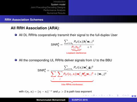
All RRH Association (ARA):
All DL RRHs cooperatively transmit their signal to the full-duplex User
SINRAd =
∑i∈Φd
Pb`(xi )|h†i wt,i |2
Pu |hLI|2︸ ︷︷ ︸Loopback interference
+ 1
All the corresponding UL RRHs deliver signals from U to the BBU
SINRAu =
∑j∈Φu
Pu`(xj )|w†r,j gj |2∑i
∑j
Pb`(xj , xi )|w†r,j Hjiudwt,i |2︸ ︷︷ ︸
Inter-RRHs interference
+ ‖wr,j‖2,
with `(xj , xi ) = ‖xj − xi‖−µ and µ > 2 is path loss exponent
Mohammadali Mohammadi EUSIPCO 2016

9/19
IntroductionSystem model
Joint Precoding/Decoding DesignsPerformance Analysis
Numerical Results
RRH Association Schemes
Single Best RRH Association (SRA):UL RRH with best channels to U is selected:
SINRSu =
Pu`(xp)|w†r,pgp|2
Pb`(xp, xq)|w†r,pHpqudwt,q |2︸ ︷︷ ︸
Inter-RRHs interference
+ ‖wr,p‖2.
A sectorized interference region (IR) of angle ±φ
around the U − p axis is adopted. No DL RRH
transmission is allowed within the IR:
SINRSd =
Pb`(xq)|h†q wt,q |2
Pu |hLI|2︸ ︷︷ ︸Loopback interference
+ 1.
DL
RRHBBU
Backhaul link
hq
g p
udHpq
Downlink link
Uplink link
Inter-RRHs link
DL
RRH
DL
RRH
UL
RRH
UL
RRH
φ
Interference
Region
Mohammadali Mohammadi EUSIPCO 2016

10/19
IntroductionSystem model
Joint Precoding/Decoding DesignsPerformance Analysis
Numerical Results
Optimal Processing for SRA Scheme
Objective:
– Jointly design wr,p and wt,q to maximize the sum rate of SRA scheme
Optimization problem (OP)
maxwt,q ,wr,p
RFDsum = ln
(1 + a1‖h†qwt,q‖2)+ ln
(1 +
a2‖w†r,pgp‖2
a3‖w†r,pHpqudwt,q‖2 + ‖wr,p‖2
),
s.t. ‖wr,p‖ = ‖wt,q‖ = 1,
where a1 =Pb`(xq )
Pu |hLI|2+1 , a2 = Pu`(xp), and a3 = Pb`(xp, xq).
Mohammadali Mohammadi EUSIPCO 2016

11/19
IntroductionSystem model
Joint Precoding/Decoding DesignsPerformance Analysis
Numerical Results
Optimal Processing for SRA Scheme
wr,p: Fixing wt , we get a generalized Rayleigh ratio problem whose solution is
wr,p =
(a3Hpq
udwt,qw†t,qHpq†ud + I
)−1gp∥∥∥(a3Hpq
udwt,qw†t,qHpq†ud + I
)−1gp
∥∥∥ .Substituting the wr,p into OP after some algebraic manipulation we get
maxwt,q
trace(h†q W t hq)
s.t. trace(W t (Hpq†ud gpg†p Hpq
ud − α Hpq†ud Hpq
ud)) =α
a3,
W t � 0, trace(W t ) = 1, rank(W t ) = 1,
By dropping the rank-1 constraint, the resulting problem becomes a semidefinite
program, whose solution Wt can be found by using appropriate solvers like CVX.
Mohammadali Mohammadi EUSIPCO 2016
12/19
IntroductionSystem model
Joint Precoding/Decoding DesignsPerformance Analysis
Numerical Results
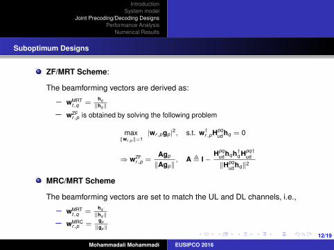
Suboptimum Designs
ZF/MRT Scheme:
The beamforming vectors are derived as:
– wMRTt,q =
hq
‖hq‖
– wZFr,p is obtained by solving the following problem
max‖wr,p‖=1
|wr,pgp|2, s.t. w†r,pHpqudhq = 0
⇒ wZFr,p =
Agp
‖Agp‖, A , I−
Hpqudhqh†q Hpq†
ud
‖Hpqudhq‖2
MRC/MRT Scheme
The beamforming vectors are set to match the UL and DL channels, i.e.,
– wMRTt,q =
hq
‖hq‖
– wMRCr,p =
gp
‖gp‖
Mohammadali Mohammadi EUSIPCO 2016
13/19
IntroductionSystem model
Joint Precoding/Decoding DesignsPerformance Analysis
Numerical Results
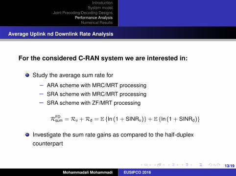
Average Uplink nd Downlink Rate Analysis
For the considered C-RAN system we are interested in:
Study the average sum rate for
– ARA scheme with MRC/MRT processing
– SRA scheme with MRC/MRT processing
– SRA scheme with ZF/MRT processing
RFDsum = Ru + Rd = E {ln (1 + SINRu)} + E {ln (1 + SINRd)}
Investigate the sum rate gains as compared to the half-duplexcounterpart
Mohammadali Mohammadi EUSIPCO 2016

14/19
IntroductionSystem model
Joint Precoding/Decoding DesignsPerformance Analysis
Numerical Results
Key Results of the Average Sum Rate Analysis
ZF/MRT processing
– Proposition 1 develops an expression for the the average sum rate
achieved by the SRA scheme.
– Proposition 3 provides an expression for the the average DL rate
achieved by the ARA scheme.
MRC/MRT processing
– Proposition 2 develops an expression for the average UL rate achieved by
the SRA scheme.
– Proposition 1 and 2 develop an expression for the average sum rate
achieved by the SRA scheme.
– Proposition 3 provides an expression for the average DL rate achieved by
the ARA scheme.
Mohammadali Mohammadi EUSIPCO 2016

15/19
IntroductionSystem model
Joint Precoding/Decoding DesignsPerformance Analysis
Numerical Results
Reference System and Simulation Parameters
Reference system: C-RAN with half-duplex user
– Orthogonal time slots for DL and UL transmissions with
RHDsum = τE
{ln(1 +
∑i∈Φd
Pb`(xi )‖h†i wt,i‖2)
}
+ (1− τ)E
{ln(1 +
∑j∈Φu
Pu`(xj )‖w†r,j gj‖2)
}.
Simulation parameters– The simulations adopt parameters of a LTE-A network5
X The power spectral density of receiver noise: −120 dBm/Hz
X The path loss exponent: α = 3
5“Radio frequency (RF) requirements for LTE pico node B," ETSI TR 136 931 V9.0.0, Tech. Rep., May 2011.
Mohammadali Mohammadi EUSIPCO 2016

16/19
IntroductionSystem model
Joint Precoding/Decoding DesignsPerformance Analysis
Numerical Results
Rate Region of the ARA and SRA Schemes
The ARA scheme results in a rate region
that is strongly biased towards UL or DL
But using the SRA scheme results in a
more balanced rate region
SRA scheme with optimal beamforming can
achieve up to 89% average sum rate gains
as compared to the half-duplex SRA
counterpart
SRA scheme with ZF/MRT beamforming
can achieve up to 80% average sum rate
gains as compared to the half-duplex SRA
counterpart
0 2 4 6 8 10 120
2
4
6
8
10
12
Average DL Rate (nat/sec/Hz)
Ave
rage
UL
Rat
e (n
at/s
ec/H
z)
FD−SRA (Optimal)FD−SRA (ZF/MRT)FD−SRA (MRC/MRT)FD−ARA (ZF/MRT)FD−ARA (MRC/MRT)HD−SRA (MRC/MRT)HD−ARA (MRC/MRT)
Figure: Rate region of the ARA and SRA schemes for full-duplexand half-duplex modes of operation (M = 3, Pu = 23 dBm,Pb = 23 dBm, and λ = 0.001).
Mohammadali Mohammadi EUSIPCO 2016

17/19
IntroductionSystem model
Joint Precoding/Decoding DesignsPerformance Analysis
Numerical Results
The Impact of the IR Region Parameter φ on the Sum Rate
Increasing the φ decreases the number of DL
RRHs and consequently the DL rate.
The UL rates of optimum and ZF/MRT designs
remain constant to produce an overall sum rate
decrease as φ is increased.
On the contrary, increasing φ improves the
performance of MRC/MRT because the
inter-RRH interference between the selected UL
RRH and DL RRH is reduced.
Clearly, increasing φ beyond its optimum value
does not improve the sum rate of MRC/MRT
processing due to the fact that there may not be
sufficient number of DL RRH inside the selection
region.
0 π/6 π/3 π/2 2π/3 5π/67
7.5
8
8.5
9
9.5
10
10.5
11
φ (rad)
UL a
nd D
L S
um
Rate
(nat/se
c/H
z)
OptimalZF/MRTMRC/MRT
Figure: Average sum rate versus φ with different beamformingdesigns (M = 2, Pu = 10 dBm, Pb = 10 dBm, andσ2
aa = −30 dBm).
Mohammadali Mohammadi EUSIPCO 2016
18/19
IntroductionSystem model
Joint Precoding/Decoding DesignsPerformance Analysis
Numerical Results
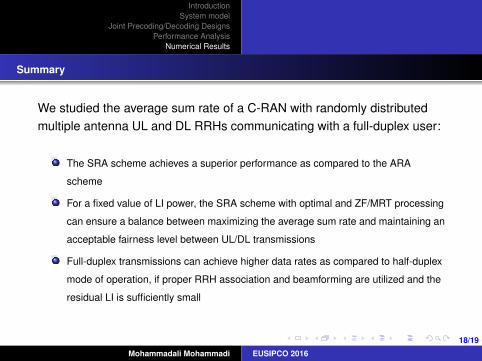
Summary
We studied the average sum rate of a C-RAN with randomly distributedmultiple antenna UL and DL RRHs communicating with a full-duplex user:
The SRA scheme achieves a superior performance as compared to the ARA
scheme
For a fixed value of LI power, the SRA scheme with optimal and ZF/MRT processing
can ensure a balance between maximizing the average sum rate and maintaining an
acceptable fairness level between UL/DL transmissions
Full-duplex transmissions can achieve higher data rates as compared to half-duplex
mode of operation, if proper RRH association and beamforming are utilized and the
residual LI is sufficiently small
Mohammadali Mohammadi EUSIPCO 2016

19/19
IntroductionSystem model
Joint Precoding/Decoding DesignsPerformance Analysis
Numerical Results
Thank you
X Mohammadali Mohammadi: [email protected]
X Himal A. Suraweera: [email protected]
X Chintha Tellambura: [email protected]
Mohammadali Mohammadi EUSIPCO 2016


![10 GSM BSS Network KPI (Uplink-Downlink Balance) Optimization Manual[1].Doc](https://img.dokumen.tips/doc/110x75/545a3905af795998788b5b03/10-gsm-bss-network-kpi-uplink-downlink-balance-optimization-manual1doc.jpg)


![10 GSM BSS Network KPI (Uplink-Downlink Balance) Optimization Manual[1].doc.doc](https://img.dokumen.tips/doc/110x75/55cf9bb1550346d033a705c6/10-gsm-bss-network-kpi-uplink-downlink-balance-optimization-manual1docdoc.jpg)