Embed Size (px)
Citation preview
9/30/2014
1
Fast Innovation requires Fast IT
High Density & High Availability in Wireless Deployment
MinSe Kim,
Sr. Technical Marketing Engineer, Cisco Systems
9/30/2014
2
3
Agenda WiFi Operation Today
WLAN RF Design Fundamental
Physical AP Placement Tips
Configuration Best Practices
Wired-Wireless Integration for HD WiFi
WiFi operation Today
9/30/2014
3
© 2014 Cisco and/or its affiliates. All rights reserved. Cisco Public
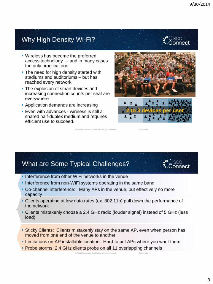
Why High Density Wi-Fi?
Wireless has become the preferred access technology -- and in many cases the only practical one
The need for high density started with stadiums and auditoriums – but has reached every network
The explosion of smart devices and increasing connection counts per seat are everywhere
Application demands are increasing
Even with advances - wireless is still a shared half-duplex medium and requires efficient use to succeed.
2 to 3 devices per user
© 2014 Cisco and/or its affiliates. All rights reserved. Cisco Public
What are Some Typical Challenges?
Interference from other WiFi networks in the venue
Interference from non-WiFi systems operating in the same band
Co-channel interference: Many APs in the venue, but effectively no more capacity
Clients operating at low data rates (ex. 802.11b) pull down the performance of the network
Clients mistakenly choose a 2.4 GHz radio (louder signal) instead of 5 GHz (less load)
Sticky Clients: Clients mistakenly stay on the same AP, even when person has moved from one end of the venue to another
Limitations on AP installable location. Hard to put APs where you want them
Probe storms: 2.4 GHz clients probe on all 11 overlapping channels
9/30/2014
4
© 2014 Cisco and/or its affiliates. All rights reserved. Cisco Public
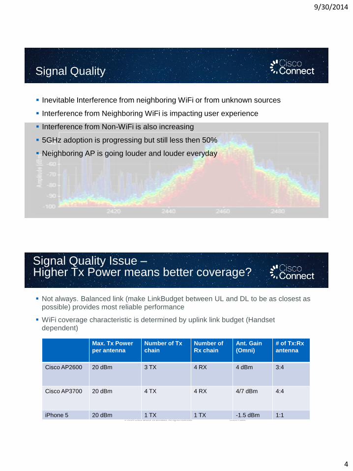
Signal Quality
Inevitable Interference from neighboring WiFi or from unknown sources
Interference from Neighboring WiFi is impacting user experience
Interference from Non-WiFi is also increasing
5GHz adoption is progressing but still less then 50%
Neighboring AP is going louder and louder everyday
© 2014 Cisco and/or its affiliates. All rights reserved. Cisco Public
Signal Quality Issue –Higher Tx Power means better coverage?
Not always. Balanced link (make LinkBudget between UL and DL to be as closest as possible) provides most reliable performance
WiFi coverage characteristic is determined by uplink link budget (Handset dependent)
Max. Tx Power
per antenna
Number of Tx
chain
Number of
Rx chain
Ant. Gain
(Omni)
# of Tx:Rx
antenna
Cisco AP2600 20 dBm 3 TX 4 RX 4 dBm 3:4
Cisco AP3700 20 dBm 4 TX 4 RX 4/7 dBm 4:4
iPhone 5 20 dBm 1 TX 1 TX -1.5 dBm 1:1
9/30/2014
5
© 2014 Cisco and/or its affiliates. All rights reserved. Cisco Public
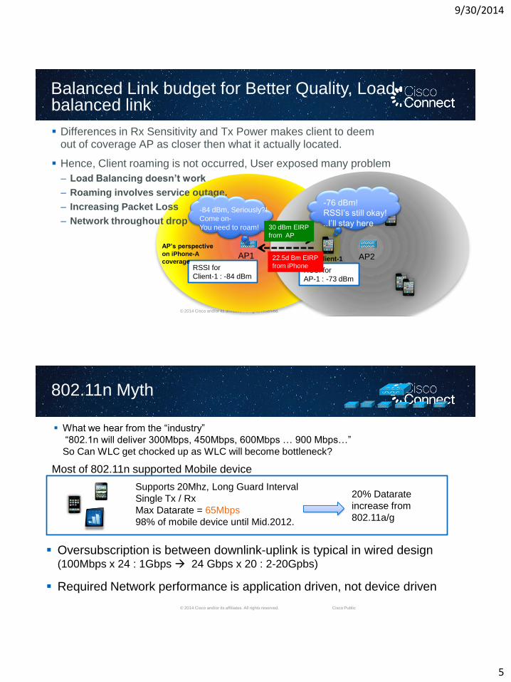
Balanced Link budget for Better Quality, Load-balanced link
Differences in Rx Sensitivity and Tx Power makes client to deem out of coverage AP as closer then what it actually located.
Hence, Client roaming is not occurred, User exposed many problem
– Load Balancing doesn’t work
– Roaming involves service outage.
– Increasing Packet Loss
– Network throughout drop
AP1 AP2
RSSI for
Client-1 : -84 dBm
AP’s perspective
on iPhone-A
coverage
RSSI for
AP-1 : -73 dBm
Client-1
-76 dBm!
RSSI’s still okay!
..I’ll stay here30 dBm EIRP
from AP
22.5d Bm EIRP
from iPhone
-84 dBm, Seriously?!
Come on-
You need to roam!
© 2014 Cisco and/or its affiliates. All rights reserved. Cisco Public
802.11n Myth
What we hear from the ―industry‖
―802.1n will deliver 300Mbps, 450Mbps, 600Mbps … 900 Mbps…‖
So Can WLC get chocked up as WLC will become bottleneck?
Most of 802.11n supported Mobile device
Supports 20Mhz, Long Guard Interval
Single Tx / Rx
Max Datarate = 65Mbps
98% of mobile device until Mid.2012.
20% Datarate
increase from
802.11a/g
Oversubscription is between downlink-uplink is typical in wired design (100Mbps x 24 : 1Gbps 24 Gbps x 20 : 2-20Gpbs)
Required Network performance is application driven, not device driven
9/30/2014
6
© 2014 Cisco and/or its affiliates. All rights reserved. Cisco Public
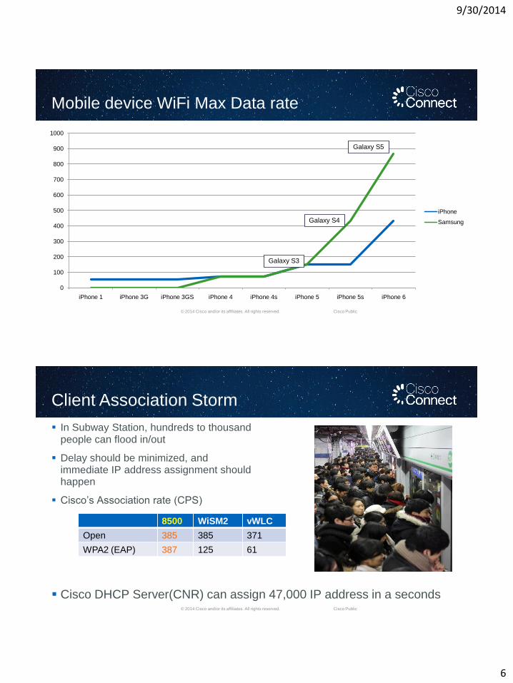
Mobile device WiFi Max Data rate
0
100
200
300
400
500
600
700
800
900
1000
iPhone 1 iPhone 3G iPhone 3GS iPhone 4 iPhone 4s iPhone 5 iPhone 5s iPhone 6
iPhone
Samsung
Galaxy S5
Galaxy S4
Galaxy S3
© 2014 Cisco and/or its affiliates. All rights reserved. Cisco Public
Client Association Storm
In Subway Station, hundreds to thousandpeople can flood in/out
Delay should be minimized, andimmediate IP address assignment shouldhappen
Cisco’s Association rate (CPS)
Cisco DHCP Server(CNR) can assign 47,000 IP address in a seconds
8500 WiSM2 vWLC
Open 385 385 371
WPA2 (EAP) 387 125 61
9/30/2014
7
© 2014 Cisco and/or its affiliates. All rights reserved. Cisco Public
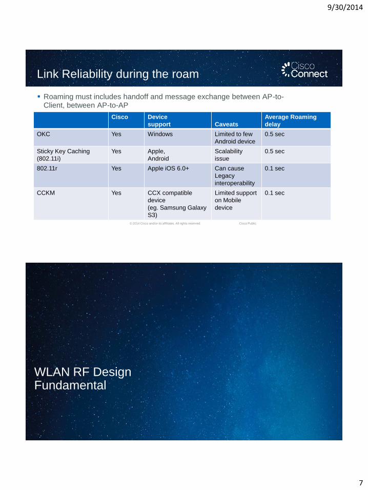
Link Reliability during the roam
Roaming must includes handoff and message exchange between AP-to-Client, between AP-to-AP
Cisco Device
support Caveats
Average Roaming
delay
OKC Yes Windows Limited to few
Android device
0.5 sec
Sticky Key Caching
(802.11i)
Yes Apple,
Android
Scalability
issue
0.5 sec
802.11r Yes Apple iOS 6.0+ Can cause
Legacy
interoperability
0.1 sec
CCKM Yes CCX compatible
device
(eg. Samsung Galaxy
S3)
Limited support
on Mobile
device
0.1 sec
WLAN RF DesignFundamental
9/30/2014
8
© 2014 Cisco and/or its affiliates. All rights reserved. Cisco Public
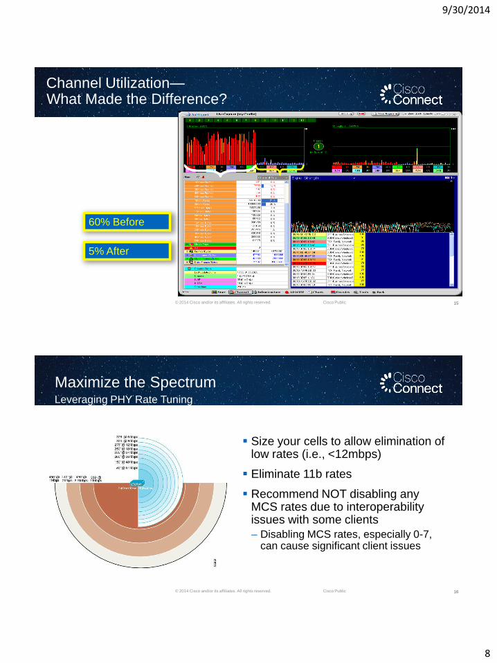
Channel Utilization—What Made the Difference?
15
5% After
60% Before
© 2014 Cisco and/or its affiliates. All rights reserved. Cisco Public
Maximize the SpectrumLeveraging PHY Rate Tuning
16
Size your cells to allow elimination of low rates (i.e., <12mbps)
Eliminate 11b rates
Recommend NOT disabling any MCS rates due to interoperability issues with some clients
– Disabling MCS rates, especially 0-7, can cause significant client issues
9/30/2014
9
© 2014 Cisco and/or its affiliates. All rights reserved. Cisco Public
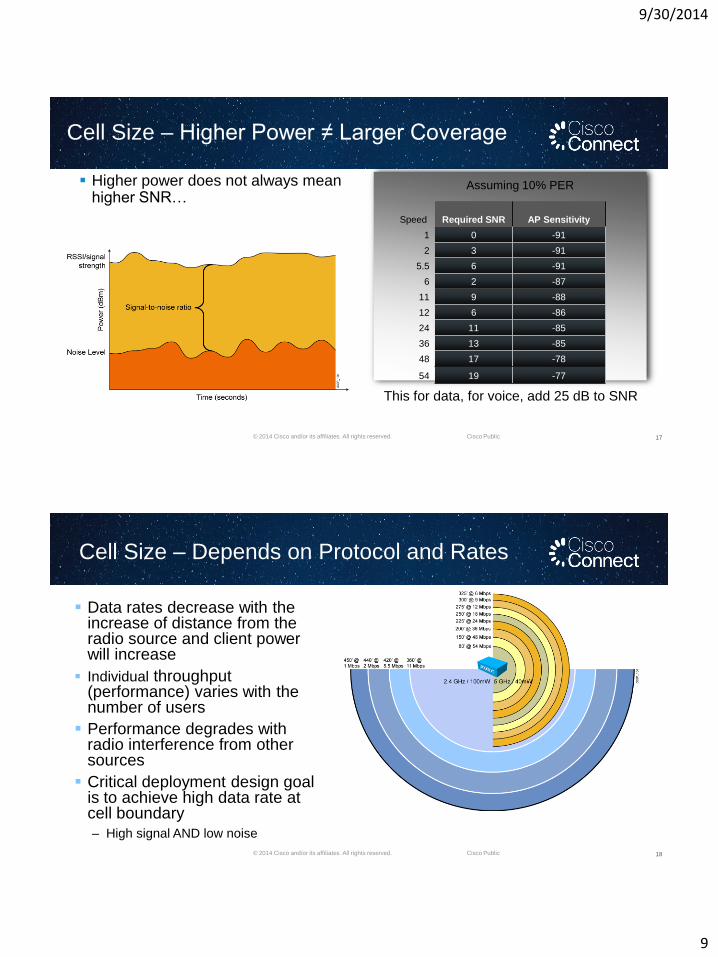
Cell Size – Higher Power ≠ Larger Coverage
Higher power does not always meanhigher SNR…
17
Assuming 10% PER
Speed Required SNR AP Sensitivity
1 0 -91
2 3 -91
5.5 6 -91
6 2 -87
11 9 -88
12 6 -86
24 11 -85
36 13 -85
48 17 -78
54 19 -77
This for data, for voice, add 25 dB to SNR
© 2014 Cisco and/or its affiliates. All rights reserved. Cisco Public
Cell Size – Depends on Protocol and Rates
18
Data rates decrease with the increase of distance from the radio source and client power will increase
Individual throughput (performance) varies with the number of users
Performance degrades with radio interference from other sources
Critical deployment design goal is to achieve high data rate at cell boundary
‒ High signal AND low noise
9/30/2014
10
© 2014 Cisco and/or its affiliates. All rights reserved. Cisco Public
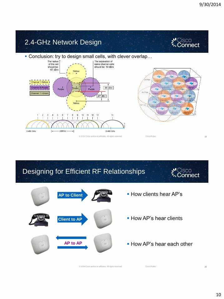
2.4-GHz Network Design
19
Conclusion: try to design small cells, with clever overlap…
© 2014 Cisco and/or its affiliates. All rights reserved. Cisco Public
Designing for Efficient RF Relationships
20
How AP’s hear each other
AP to Client
Client to AP
AP to AP
How AP’s hear clients
How clients hear AP’s
9/30/2014
11
© 2014 Cisco and/or its affiliates. All rights reserved. Cisco Public
Channel Coverage Sizing Recommendations
Coverage must be designed for your Client Devices
Not all clients are created equal !!!
1. Live call test with the actual client to determine its coverage
Removing legacy DSSS data rates and slower OFDM data rates from the WLC configuration equals:
1. Less Co-Channel Interference
2. Better throughput in the cell
3. More usage of ClientLink and MRC
4. Smaller coverage cells
Smaller Coverage Cell Sizes equals:
1. More cells in a given coverage area
2. More cells equals more call with better voice and video quality
21
Physical AP Placement Tips
9/30/2014
12
© 2014 Cisco and/or its affiliates. All rights reserved. Cisco Public
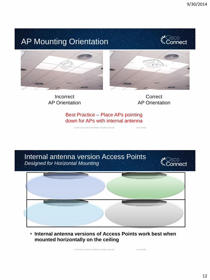
AP Mounting Orientation
Best Practice – Place APs pointing
down for APs with internal antenna
Incorrect
AP Orientation
Correct
AP Orientation
© 2014 Cisco and/or its affiliates. All rights reserved. Cisco Public
Internal antenna version Access PointsDesigned for Horizontal Mounting
Internal antenna versions of Access Points work best when mounted horizontally on the ceiling
9/30/2014
13
© 2014 Cisco and/or its affiliates. All rights reserved. Cisco Public
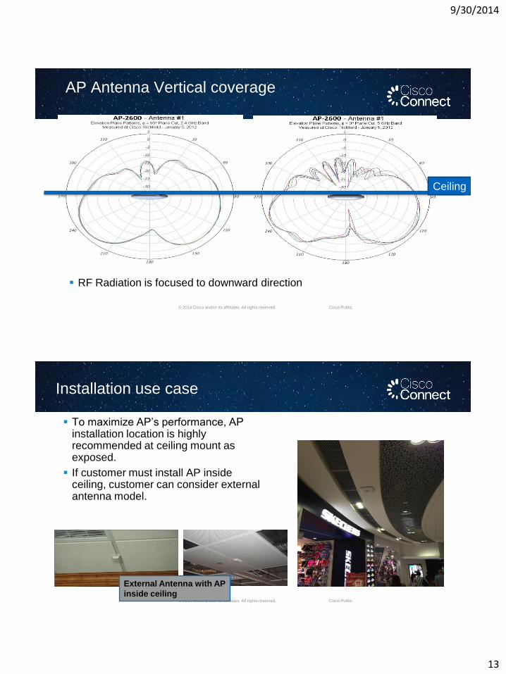
AP Antenna Vertical coverage
RF Radiation is focused to downward direction
Ceiling
© 2014 Cisco and/or its affiliates. All rights reserved. Cisco Public
Installation use case
To maximize AP’s performance, AP installation location is highly recommended at ceiling mount as exposed.
If customer must install AP inside ceiling, customer can consider external antenna model.
External Antenna with AP
inside ceiling
9/30/2014
14
© 2014 Cisco and/or its affiliates. All rights reserved. Cisco Public
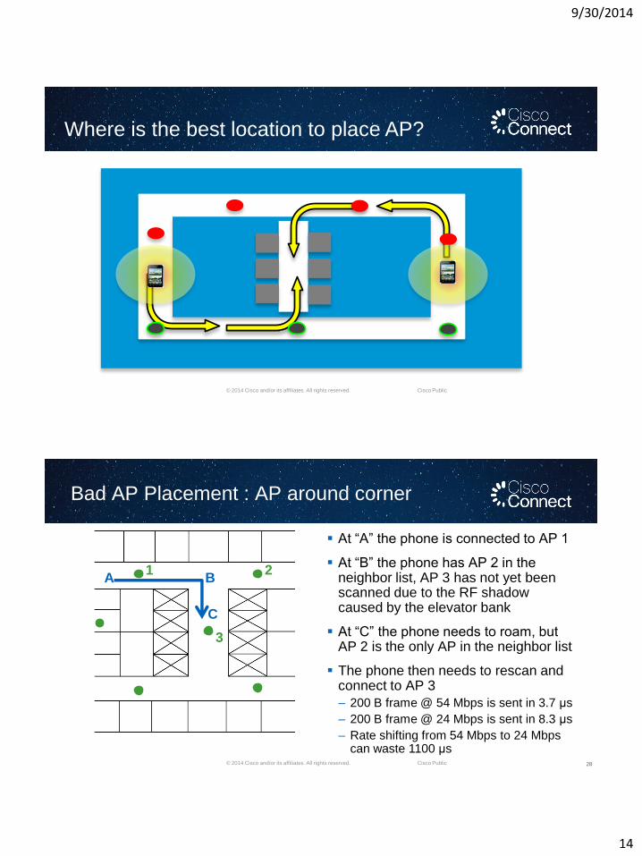
Where is the best location to place AP?
© 2014 Cisco and/or its affiliates. All rights reserved. Cisco Public
Bad AP Placement : AP around corner
28
1
3
2A B
C
At ―A‖ the phone is connected to AP 1
At ―B‖ the phone has AP 2 in the neighbor list, AP 3 has not yet been scanned due to the RF shadow caused by the elevator bank
At ―C‖ the phone needs to roam, but AP 2 is the only AP in the neighbor list
The phone then needs to rescan and connect to AP 3
– 200 B frame @ 54 Mbps is sent in 3.7 μs
– 200 B frame @ 24 Mbps is sent in 8.3 μs
– Rate shifting from 54 Mbps to 24 Mbps can waste 1100 μs
9/30/2014
15
© 2014 Cisco and/or its affiliates. All rights reserved. Cisco Public
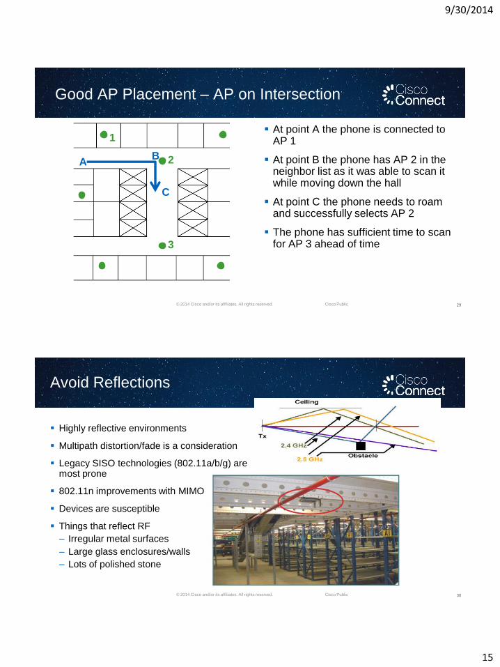
Good AP Placement – AP on Intersection
29
AB
C
1
2
3
At point A the phone is connected to AP 1
At point B the phone has AP 2 in the neighbor list as it was able to scan it while moving down the hall
At point C the phone needs to roam and successfully selects AP 2
The phone has sufficient time to scan for AP 3 ahead of time
© 2014 Cisco and/or its affiliates. All rights reserved. Cisco Public
Avoid Reflections
Highly reflective environments
Multipath distortion/fade is a consideration
Legacy SISO technologies (802.11a/b/g) are most prone
802.11n improvements with MIMO
Devices are susceptible
Things that reflect RF
– Irregular metal surfaces
– Large glass enclosures/walls
– Lots of polished stone
30
9/30/2014
16
© 2014 Cisco and/or its affiliates. All rights reserved. Cisco Public
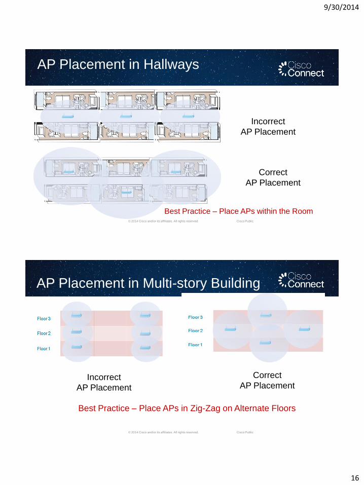
AP Placement in Hallways
Incorrect
AP Placement
Correct
AP Placement
Best Practice – Place APs within the Room
© 2014 Cisco and/or its affiliates. All rights reserved. Cisco Public
AP Placement in Multi-story Building
Incorrect
AP Placement
Correct
AP Placement
Best Practice – Place APs in Zig-Zag on Alternate Floors
9/30/2014
17
WiFi Best Practices
© 2014 Cisco and/or its affiliates. All rights reserved. Cisco Public
Lower 2.4 speeds not turned off -1,2,5.5,6,9 Meg
Enable 2.4 GHz and 5 GHz bands
Guest & Admin on separate SSIDs and VLANs
802.11n throughout most of the property
802.11ac in spaces with high device density
General RF Recommendations
9/30/2014
18
Wired-Wireless Integration for HD WiFi
© 2014 Cisco and/or its affiliates. All rights reserved. Cisco Public
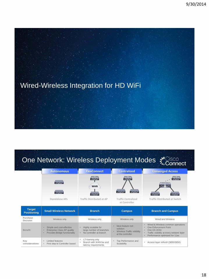
Autonomous FlexConnect Centralized Converged Access
Traffic Distributed at AP Traffic Centralized at Controller
Traffic Distributed at SwitchStandalone APs
Target
PositioningSmall Wireless Network Branch Campus Branch and Campus
Purchase
DecisionWireless only Wireless only Wireless only Wired and Wireless
Benefit
• Simple and cost-effective
• Enterprise Class AP quality
• Provides Bridge functionality
• Highly scalable for
large number of branches
• No controller at branch
• Most feature rich
solution
• Wireless Traffic visibility
at the controller
• Wired & Wireless common operations
• One Enforcement Point
• One OS (IOS)
• Traffic visibility at every network layer
• Performance optimized for 11ac
Key
considerations
• Limited features
• First step to Controller based
• L2 roaming only
• Branch with WAN bw and
latency requirements
• Top Performance and
Scalability• Access layer refresh (3650/3850)
WAN
One Network: Wireless Deployment Modes
9/30/2014
19
© 2014 Cisco and/or its affiliates. All rights reserved. Cisco Public
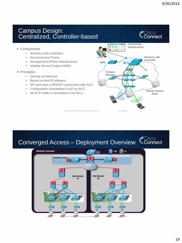
Campus Design: Centralized, Controller-based
Components
• Wireless LAN controllers
• Aironet Access Points
• Management (Prime Infrastructure)
• Mobility Service Engine (MSE)
Principles
• Overlay Architecture
• Based on AireOS software
• AP must have CAPWAP connectivity with WLC
• Configuration downloaded to AP by WLC
• All Wi-Fi traffic is forwarded to the WLC
Wireless LAN
Controller
Aironet Access
Point
Cisco Prime
Infrastructure
MSE
Campus
Network
© 2014 Cisco and/or its affiliates. All rights reserved. Cisco Public
Converged Access – Deployment Overview
Mobility Domain MO
Sub-Domain
#1
Sub-Domain
#2
Mobility Group
SPG SPG
PIISE
MAMAMA MAMAMA
MCMC
9/30/2014
20
© 2014 Cisco and/or its affiliates. All rights reserved. Cisco Public
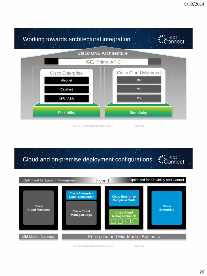
SimplicityFlexibility
ISE, Prime, APIC
Working towards architectural integration
Aironet
Catalyst
ISR / ASA
Cisco Enterprise
Cisco ONE Architecture
MR
MS
MX
Cisco Cloud Managed
© 2014 Cisco and/or its affiliates. All rights reserved. Cisco Public
Cloud and on-premise deployment configurations
Cisco
Enterprise
Cisco Enterprise
Campus & WAN
Cisco Cloud
Managed Branch
Cisco Cloud
Managed Edge
Cisco Enterprise
Core / Datacenter
Cisco
Cloud Managed
Mid-Market Business Enterprise and Mid-Market Business
Optimized for Ease of Management Optimized for Flexibility and ControlHybrid
9/30/2014
21
© 2014 Cisco and/or its affiliates. All rights reserved. Cisco Public
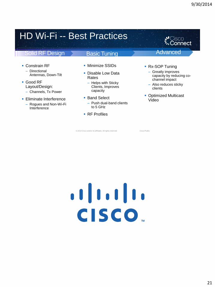
Constrain RF
– Directional Antennas, Down-Tilt
Good RF Layout/Design:
– Channels, Tx Power
Eliminate Interference
– Rogues and Non-Wi-Fi Interference
Minimize SSIDs
Disable Low Data Rates
– Helps with Sticky Clients, Improves capacity
Band Select
– Push dual-band clients to 5 GHz
RF Profiles
Rx-SOP Tuning
– Greatly improves capacity by reducing co-channel impact
– Also reduces sticky clients
Optimized Multicast Video
AdvancedSolid RF Design Basic Tuning
HD Wi-Fi -- Best Practices
9/30/2014
22
Backup Slides
© 2014 Cisco and/or its affiliates. All rights reserved. Cisco Public
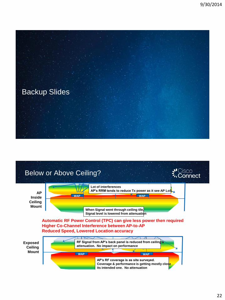
Below or Above Ceiling?
WAP WAP
AP’s RF coverage is as site surveyed.
Coverage & performance is getting mostly close
its intended one. No attenuation
RF Signal from AP’s back panel is reduced from ceiling’s
attenuation. No impact on performanceExposed
Ceiling
Mount
WAPWAP
When Signal went through ceiling tile,
Signal level is lowered from attenuation
Lot of interferences
AP’s RRM tends to reduce Tx power as it see AP LoSAP
Inside
Ceiling
Mount
Automatic RF Power Control (TPC) can give less power then required
Higher Co-Channel Interference between AP-to-AP
Reduced Speed, Lowered Location accuracy
9/30/2014
23
© 2014 Cisco and/or its affiliates. All rights reserved. Cisco Public
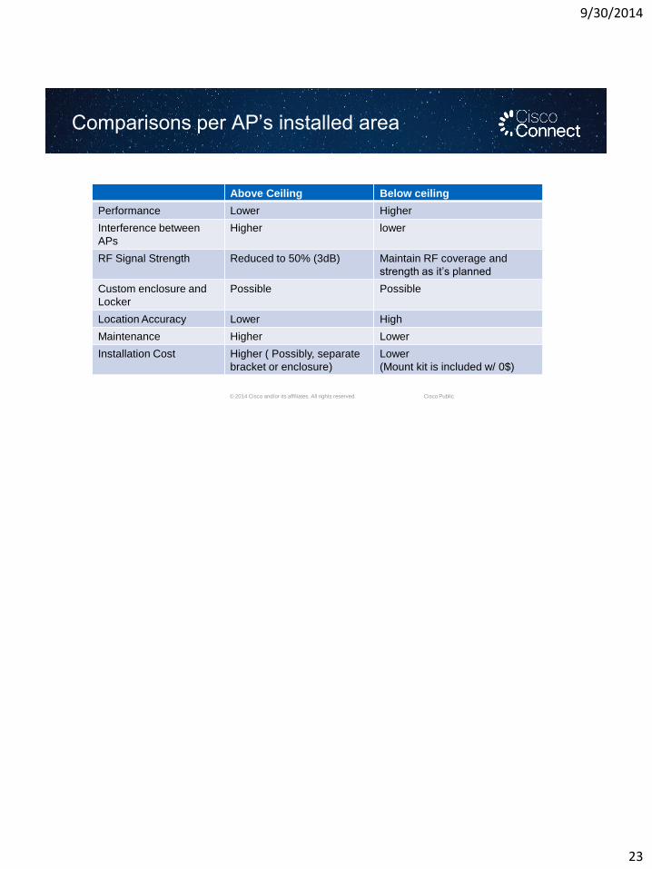
Comparisons per AP’s installed area
Above Ceiling Below ceiling
Performance Lower Higher
Interference between
APs
Higher lower
RF Signal Strength Reduced to 50% (3dB) Maintain RF coverage and
strength as it’s planned
Custom enclosure and
Locker
Possible Possible
Location Accuracy Lower High
Maintenance Higher Lower
Installation Cost Higher ( Possibly, separate
bracket or enclosure)
Lower
(Mount kit is included w/ 0$)