Embed Size (px)
Citation preview
UniGear type ZS2Medium voltage, arc-proof, air-insulated,metal-clad switchgear
UniGear type ZS2 is the new name of well-established UniSafe 36 switchgear.
The product is identical to Unisafe 36 without any technical difference.Therefore all related technical documentation under the name of UniSafe 36 willbe valid and applicable to the product with the name of UniGear type ZS2.
Name change was done because of product portfolio and classification reasons.
Supplementary official acclaimer letter from ABB, could be submitted along withthe product and technical documentation, upon request.
1
12
24
36
48
511
613
7
14
916
1017
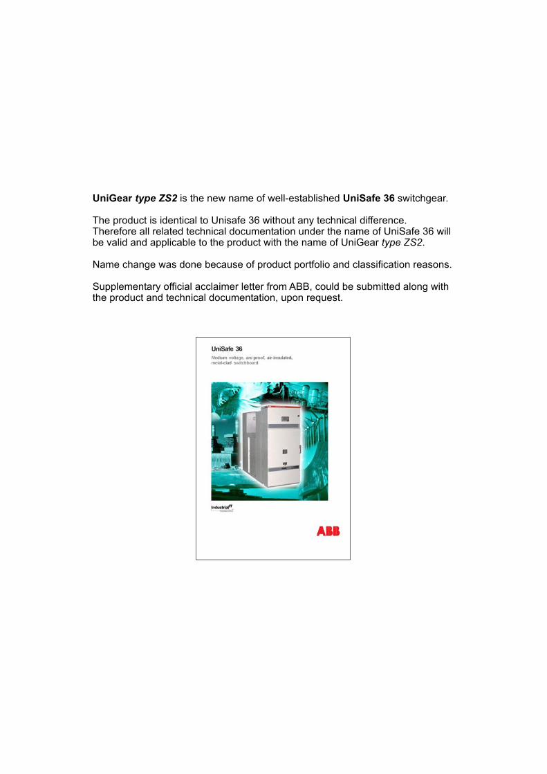
14SERVICE TRUCKS
815
CHARACTERISTICS AND APPLICATIONS
DESCRIPTION
APPARATUS
SWITCHBOARD CHARACTERISTICS
PROTECTION AND CONTROL
INSTRUMENT TRANSFORMERS
TECHNICAL DATA
TYPICAL UNITS
PROTECTION AGAINST TO INTERNAL ARC
2
CHARACTERISTICS AND APPLICATIONS
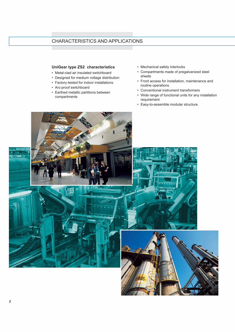
UniGear type ZS2 characteristics• Metal-clad air insulated switchboard• Designed for medium voltage distribution• Factory-tested for indoor installations• Arc-proof switchboard• Earthed metallic partitions between
compartments
• Mechanical safety interlocks• Compartments made of pregalvanized steel
sheets• Front access for installation, maintenance and
routine operations• Conventional instrument transformers• Wide range of functional units for any installation
requirement• Easy-to-assemble modular structure.
3
1
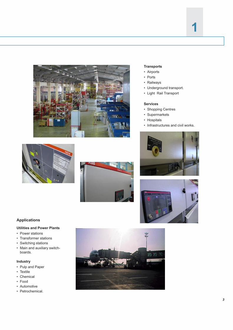
Transports• Airports• Ports• Railways• Underground transport.• Light Rail Transport
Services• Shopping Centres• Supermarkets• Hospitals• Infrastructures and civil works.
Applications
Utilities and Power Plants• Power stations• Transformer stations• Switching stations• Main and auxiliary switch-
boards.
Industry• Pulp and Paper• Textile• Chemical• Food• Automotive• Petrochemical.
4
Thanks to compactness, reduced footprint and thepossibility of placing the switchboard against theinstallation room walls of UniGear.
All the operations can be carried out from the frontof the switchboard.
The switchboard is also available in the Back toBack arrangement version for carrying out doublebusbar system configurations.
The entire busbar system (main and branches) ismade with insulated round bars.
Apart from making the main busbar systeminstallation operations extremely simple, thesecharacteristics help to guarantee the performancesrequired by a 36 kV air insulated switchboard.
In order to ensure easy access to the feedercompartment and, at the same time, not to in-crease the switchboard dimensions, the transform-ers for current measurement are specially posi-tioned with a particular triangular shape.
This special layout of the transformers allows allthe electrical parameters of the switchboard andensures more space for the operators duringerection and maintenance procedures.
Metal sheets segregate each compartment and theenergised components are air insulated.
The arc-proof units have been tested in compliancewith IEC 60298 Standards.
The installation requires very simple civil works.The switchboard can be wall-mounted.
The power cables terminals are accessible fromthe front.
Protection degreesThe protection degrees in compliance with IEC60529 Standards are the following:• IP4X on the external housing• IP2X inside the compartments.Cubicles with higher protection degrees (up to amaximum of IP52) can be manufactured uponrequest.
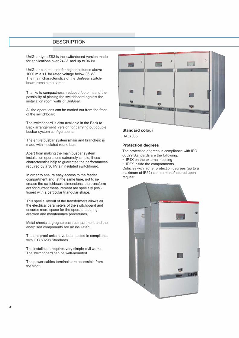
DESCRIPTION
UniGear type ZS2 is the switchboard version madefor applications over 24kV and up to 36 kV.
UniGear can be used for higher altitudes above1000 m a.s.l. for rated voltage below 36 kV.The main characteristics of the UniGear switch-board remain the same.
Standard colourRAL7035
5
2
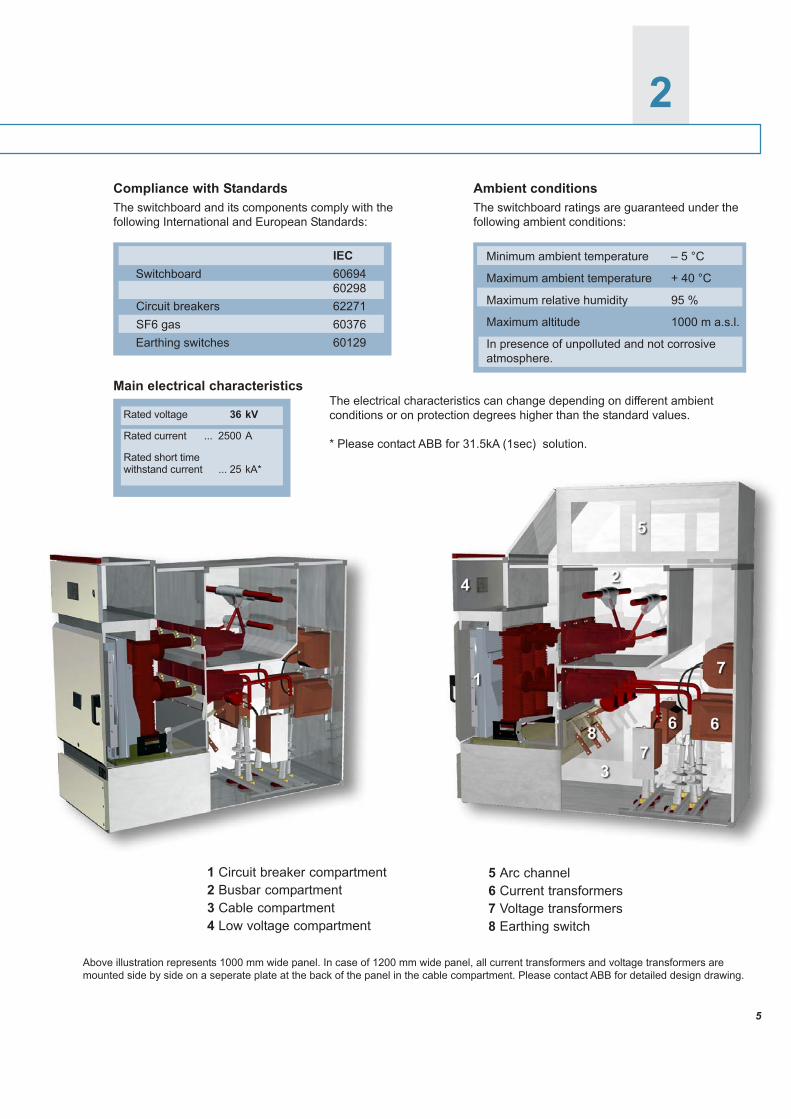
Above illustration represents 1000 mm wide panel. In case of 1200 mm wide panel, all current transformers and voltage transformers aremounted side by side on a seperate plate at the back of the panel in the cable compartment. Please contact ABB for detailed design drawing.
1 Circuit breaker compartment2 Busbar compartment3 Cable compartment4 Low voltage compartment
Main electrical characteristicsThe electrical characteristics can change depending on different ambientconditions or on protection degrees higher than the standard values.
* Please contact ABB for 31.5kA (1sec) solution.
Compliance with StandardsThe switchboard and its components comply with thefollowing International and European Standards:
5 Arc channel6 Current transformers7 Voltage transformers8 Earthing switch
Ambient conditionsThe switchboard ratings are guaranteed under thefollowing ambient conditions:
IEC Switchboard 60694
60298 Circuit breakers 62271 SF6 gas 60376 Earthing switches 60129
Minimum ambient temperature – 5 °C
Maximum ambient temperature + 40 °C
Maximum relative humidity 95 %
Maximum altitude 1000 m a.s.l.
In presence of unpolluted and not corrosiveatmosphere.
Rated voltage 36 kV
Rated current ... 2500 A
Rated short time withstand current ... 25 kA*
6
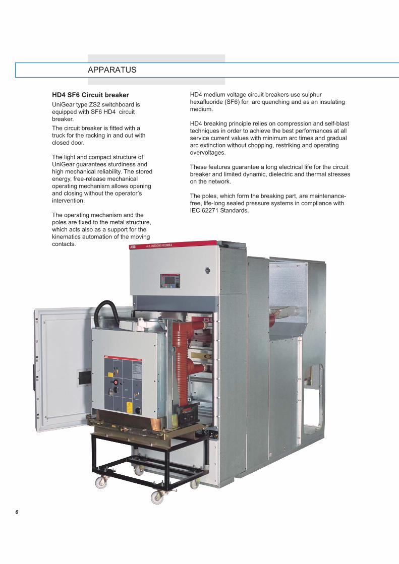
APPARATUS
HD4 medium voltage circuit breakers use sulphurhexafluoride (SF6) for arc quenching and as an insulatingmedium.
HD4 breaking principle relies on compression and self-blasttechniques in order to achieve the best performances at allservice current values with minimum arc times and gradualarc extinction without chopping, restriking and operatingovervoltages.
These features guarantee a long electrical life for the circuitbreaker and limited dynamic, dielectric and thermal stresseson the network.
The poles, which form the breaking part, are maintenance-free, life-long sealed pressure systems in compliance withIEC 62271 Standards.
HD4 SF6 Circuit breakerUniGear type ZS2 switchboard isequipped with SF6 HD4 circuitbreaker.The circuit breaker is fitted with atruck for the racking in and out withclosed door.
The light and compact structure ofUniGear guarantees sturdiness andhigh mechanical reliability. The storedenergy, free-release mechanicaloperating mechanism allows openingand closing without the operator’sintervention.
The operating mechanism and thepoles are fixed to the metal structure,which acts also as a support for thekinematics automation of the movingcontacts.
7
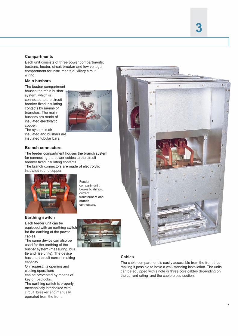
3SWITCHBOARD CHARACTERISTICS
CablesThe cable compartment is easily accessible from the front thusmaking it possible to have a wall-standing installation. The unitscan be equipped with single or three core cables depending onthe current rating and the cable cross-section.
Branch connectorsThe feeder compartment houses the branch systemfor connecting the power cables to the circuitbreaker fixed insulating contacts.The branch connectors are made of electrolyticinsulated round copper.
CompartmentsEach unit consists of three power compartments;busbars, feeder, circuit breaker and low voltagecompartment for instruments,auxiliary circuitwiring.Main busbarsThe busbar compartmenthouses the main busbarsystem, which isconnected to the circuitbreaker fixed insulatingcontacts by means ofbranches. The mainbusbars are made ofinsulated electrolyticcopper.The system is air-insulated and busbars areinsulated tubular bars.
Feedercompartment :Lower bushings,currenttransformers andbranchconnectors.
Earthing switchEach feeder unit can beequipped with an earthing switchfor the earthing of the powercables.The same device can also beused for the earthing of thebusbar system (measuring, bustie and rise units). The devicehas short circuit current makingcapacity.On request, its opening andclosing operationscan be prevented by means ofkey or padlocks.The earthing switch is properlymechanicaly interlocked withcircuit breaker and manuallyoperated from the front
8
4
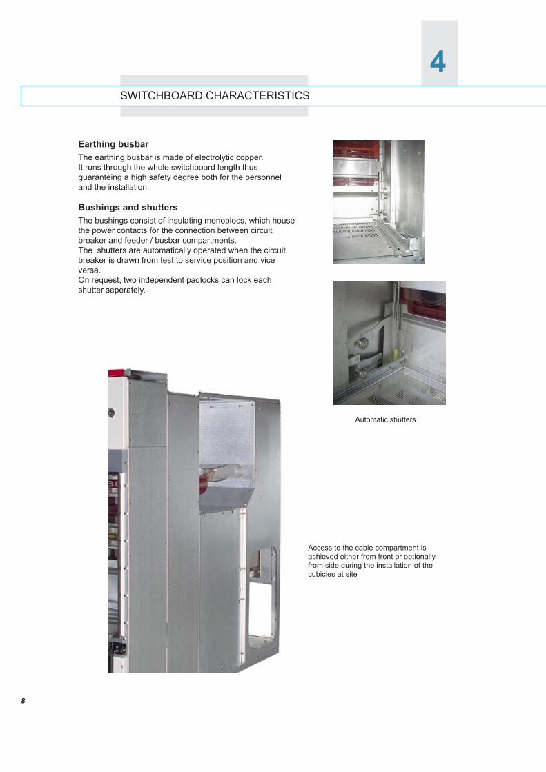
Earthing busbarThe earthing busbar is made of electrolytic copper.It runs through the whole switchboard length thusguaranteing a high safety degree both for the personneland the installation.
Bushings and shuttersThe bushings consist of insulating monoblocs, which housethe power contacts for the connection between circuitbreaker and feeder / busbar compartments.The shutters are automatically operated when the circuitbreaker is drawn from test to service position and viceversa.On request, two independent padlocks can lock eachshutter seperately.
SWITCHBOARD CHARACTERISTICS
Access to the cable compartment isachieved either from front or optionallyfrom side during the installation of thecubicles at site
Automatic shutters
9
SWITCHBOARD CHARACTERISTICS
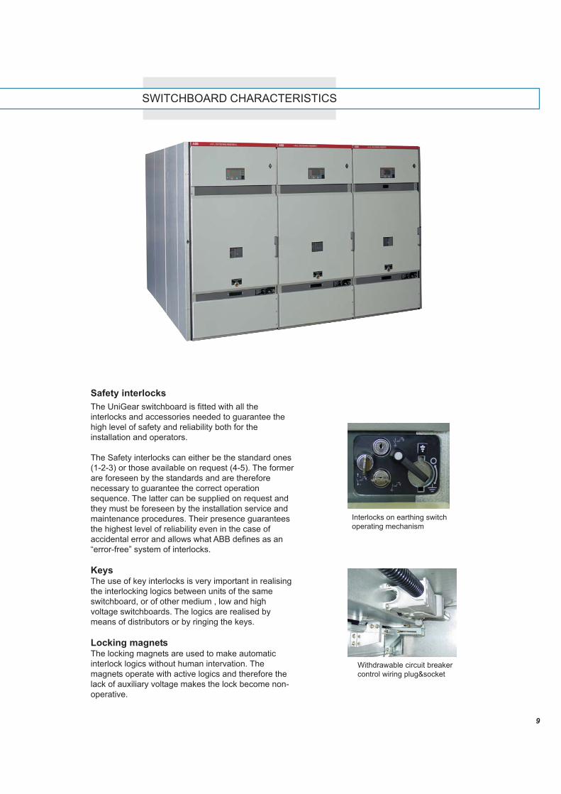
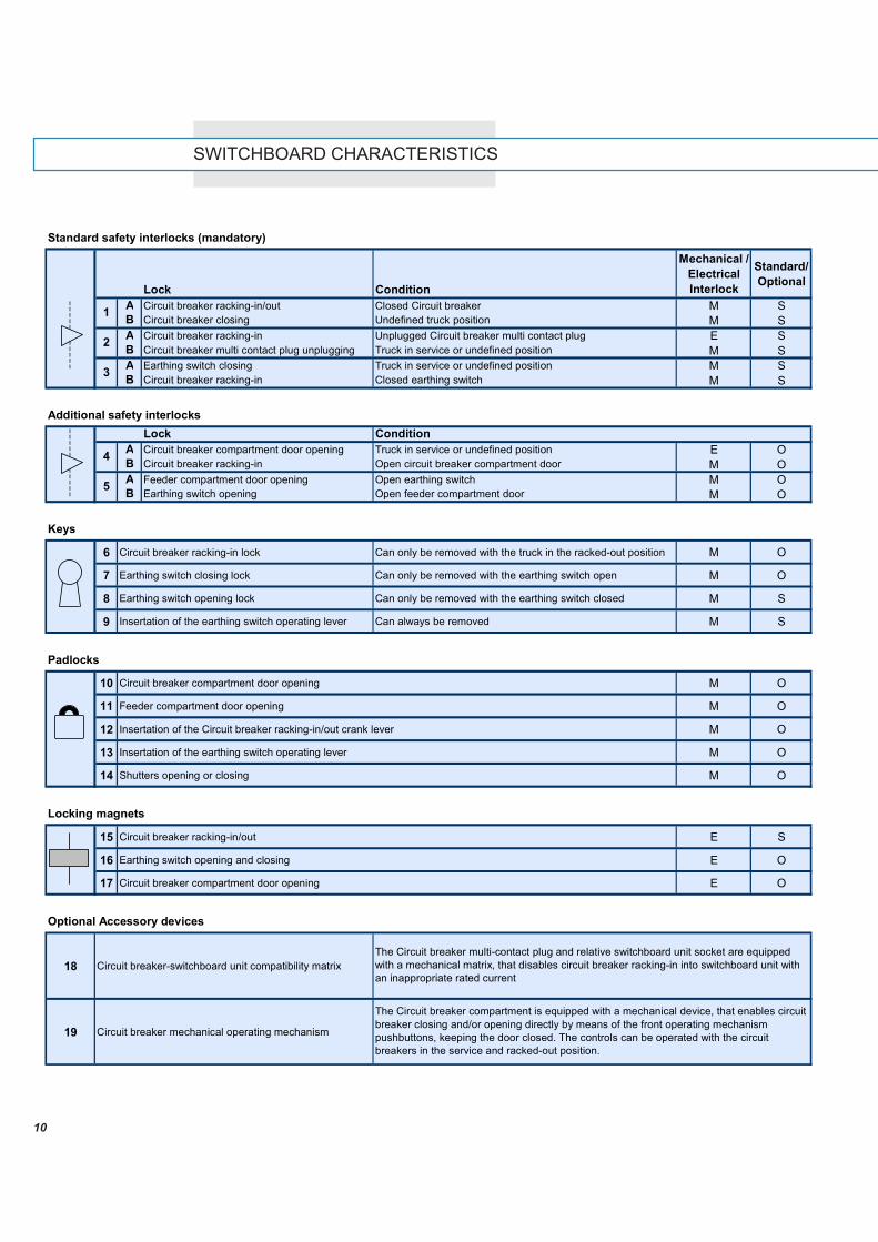
Safety interlocksThe UniGear switchboard is fitted with all theinterlocks and accessories needed to guarantee thehigh level of safety and reliability both for theinstallation and operators.
The Safety interlocks can either be the standard ones(1-2-3) or those available on request (4-5). The formerare foreseen by the standards and are thereforenecessary to guarantee the correct operationsequence. The latter can be supplied on request andthey must be foreseen by the installation service andmaintenance procedures. Their presence guaranteesthe highest level of reliability even in the case ofaccidental error and allows what ABB defines as an“error-free” system of interlocks.
KeysThe use of key interlocks is very important in realisingthe interlocking logics between units of the sameswitchboard, or of other medium , low and highvoltage switchboards. The logics are realised bymeans of distributors or by ringing the keys.
Locking magnetsThe locking magnets are used to make automaticinterlock logics without human intervation. Themagnets operate with active logics and therefore thelack of auxiliary voltage makes the lock become non-operative.
Withdrawable circuit breakercontrol wiring plug&socket
Interlocks on earthing switchoperating mechanism
10
SWITCHBOARD CHARACTERISTICS
Standard safety interlocks (mandatory)
Lock Condition
Mechanical / Electrical Interlock
Standard/Optional
A Circuit breaker racking-in/out Closed Circuit breaker M SB Circuit breaker closing Undefined truck position M SA Circuit breaker racking-in Unplugged Circuit breaker multi contact plug E SB Circuit breaker multi contact plug unplugging Truck in service or undefined position M SA Earthing switch closing Truck in service or undefined position M SB Circuit breaker racking-in Closed earthing switch M S
Additional safety interlocksLock Condition
A Circuit breaker compartment door opening Truck in service or undefined position E OB Circuit breaker racking-in Open circuit breaker compartment door M OA Feeder compartment door opening Open earthing switch M OB Earthing switch opening Open feeder compartment door M O
Keys
6 Circuit breaker racking-in lock Can only be removed with the truck in the racked-out position M O
7 Earthing switch closing lock Can only be removed with the earthing switch open M O
8 Earthing switch opening lock Can only be removed with the earthing switch closed M S
9 Insertation of the earthing switch operating lever Can always be removed M S
Padlocks
10 Circuit breaker compartment door opening M O
11 Feeder compartment door opening M O
12 Insertation of the Circuit breaker racking-in/out crank lever M O
13 Insertation of the earthing switch operating lever M O
14 Shutters opening or closing M O
Locking magnets
15 Circuit breaker racking-in/out E S
16 Earthing switch opening and closing E O
17 Circuit breaker compartment door opening E O
Optional Accessory devices
18 Circuit breaker-switchboard unit compatibility matrix
19 Circuit breaker mechanical operating mechanism
The Circuit breaker multi-contact plug and relative switchboard unit socket are equipped with a mechanical matrix, that disables circuit breaker racking-in into switchboard unit with an inappropriate rated current
The Circuit breaker compartment is equipped with a mechanical device, that enables circuit breaker closing and/or opening directly by means of the front operating mechanism pushbuttons, keeping the door closed. The controls can be operated with the circuit breakers in the service and racked-out position.
5
1
2
3
4
11
5PROTECTION AND CONTROL
Thanks to the use of the REF542plus unit, eachmedium voltage UniGear panel becomes anintegrated and independent unit able to carry out allthe required functions.• Integration of all the functions in a single
instrument: protection, measurement, controls,signalling, interlocking, automation and commu-nication.
• Single interface between switchboard andoperator for all the installation panels: feeder,transformer, motor, generator, power correctionbanks, bus-tie and measurements units.
• Single type of spares parts and accessories: asingle hardware unit.
• Reduced maintenance: drastic reduction inpreventive maintenance, great limitation of thefaults caused by tampering and errors.
• Easy modification and upgrading of the functions:by means of the unit configuration software, evenwith the switchboard in service.
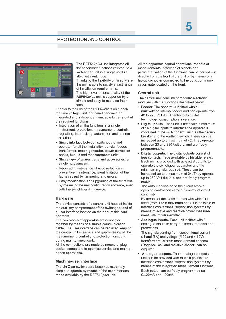
HardwareThe device consists of a central unit housed insidethe auxiliary compartment of the switchgear and ofa user interface located on the door of this com-partment.The two pieces of apparatus are connectedtogether by means of a simple communicationcable. The user interface can be replaced keepingthe central unit in service and guaranteeing all themeasurement, control and protection functionsduring maintenance work.All the connections are made by means of plug-socket connectors to optimise service and mainte-nance operations.
Machine-user interfaceThe UniGear switchboard becomes extremelysimple to operate by means of the user interfacemade available by the REF542plus unit.
All the apparatus control operations, readout ofmeasurements, detection of signals andparameterisation of the functions can be carried outdirectly from the front of the unit or by means of alaptop computer connected to the optic communi-cation gate located on the front.
Central unitThe central unit consists of modular electronicmodules with the functions described below.• Feeder. The apparatus is fitted with a
multivoltage internal feeder and can operate from48 to 220 Volt d.c. Thanks to its digitaltechnology, consumption is very low.
• Digital inputs. Each unit is fitted with a minimumof 14 digital inputs to interface the apparatuscontained in the switchboard, such as the circuit-breaker and the earthing switch. These can beincreased up to a maximum of 42. They operatebetween 20 and 250 Volt d.c. and are freelyprogrammable.
• Digital outputs. The digital outputs consist offree contacts made available by bistable relays.Each unit is provided with at least 8 outputs tooperate the switchgear apparatus and theminimum signals required. These can beincreased up to a maximum of 24. They operateup to 250 Volt d.c./a.c. and are freely program-mable.The output dedicated to the circuit-breakeropening control can carry out control of circuitcontinuity.By means of the static outputs with which it isfitted (from 1 to a maximum of 3), it is possible tointerface conventional supervision systems bymeans of active and reactive power measure-ment with impulse emitter.
• Analogue inputs. Each unit is fitted with 8analogue inputs to carry out measurements andprotections.The signals coming from conventional current(/1 and /5A) and voltage (/100 and /110V)transformers, or from measurement sensors(Rogowski coil and resistive divider) can beacquired.
• Analogue outputs. The 4 analogue outputs theunit can be provided with make it possible tointerface conventional supervision systems bymeans of the integrated measurement functions.Each output can be freely programmed as0...20mA or 4...20mA.
The REF542plus unit integrates allthe secondary functions relevant to aswitchgear unit in a single modulefitted with watchdog.Thanks to the flexibility of its software,the unit is able to satisfy a vast rangeof installation requirements.The high level of functionality of theREF542plus unit is supported by asimple and easy-to-use user inter-face.
12
REF542plus REF542plus
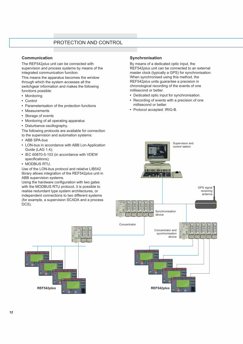
CommunicationThe REF542plus unit can be connected withsupervision and process systems by means of theintegrated communication function.This means the apparatus becomes the windowthrough which the system accesses all theswitchgear information and makes the followingfunctions possible:• Monitoring• Control• Parameterisation of the protection functions• Measurements• Storage of events• Monitoring of all operating apparatus• Disturbance oscillography.The following protocols are available for connectionto the supervision and automation systems:• ABB SPA-bus• LON-bus in accordance with ABB Lon Application
Guide (LAG 1.4);• IEC 60870-5-103 (in accordance with VDEW
specifications);• MODBUS RTU.Use of the LON-bus protocol and relative LIB542library allows integration of the REF542plus unit inABB supervision systems.Using the hardware configuration with two gateswith the MODBUS RTU protocol, it is possible torealise redundant type system architectures, orindependent connections to two different systems(for example, a supervision SCADA and a processDCS).
SynchronisationBy means of a dedicated optic input, theREF542plus unit can be connected to an externalmaster clock (typically a GPS) for synchronisation.When synchronised using this method, theREF542plus units guarantee a precision inchronological recording of the events of onemillisecond or better.• Dedicated optic input for synchronisation.• Recording of events with a precision of one
millisecond or better.• Protocol accepted: IRIG-B.
Synchronisationdevice
GPS signalreceivingantenna
Concentrator andsynchronisation
device
Concentrator
Supervision andcontrol station
PROTECTION AND CONTROL
13
6
Voltage transformersThe resin-insulated voltage transformers are usedfor the feeding of measuring instruments andprotections. They are suitable either for fixedinstallation or mounted on withdrawable trucks.They comply with IEC 60044-2 Standards.The withdrawable version equipped with fuses iscustom-made.The voltage transformers can be fitted either withone or two poles. Their performances and accuracyclasses comply with the functional requirements ofthe apparatus they are connected to.The withdrawable version is equipped with mediumvoltage protection fuses, their replacement can becarried out while the switchboard is in service.
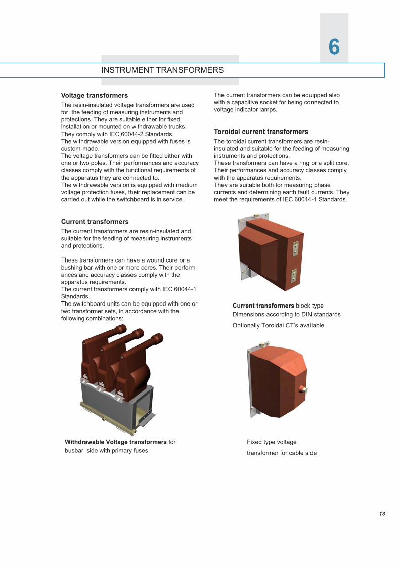
Current transformersThe current transformers are resin-insulated andsuitable for the feeding of measuring instrumentsand protections.
These transformers can have a wound core or abushing bar with one or more cores. Their perform-ances and accuracy classes comply with theapparatus requirements.The current transformers comply with IEC 60044-1Standards.The switchboard units can be equipped with one ortwo transformer sets, in accordance with thefollowing combinations:
The current transformers can be equipped alsowith a capacitive socket for being connected tovoltage indicator lamps.
Toroidal current transformersThe toroidal current transformers are resin-insulated and suitable for the feeding of measuringinstruments and protections.These transformers can have a ring or a split core.Their performances and accuracy classes complywith the apparatus requirements.They are suitable both for measuring phasecurrents and determining earth fault currents. Theymeet the requirements of IEC 60044-1 Standards.
Current transformers block typeDimensions according to DIN standards
Optionally Toroidal CT’s available
Fixed type voltage
transformer for cable side
INSTRUMENT TRANSFORMERS
Withdrawable Voltage transformers forbusbar side with primary fuses
INSTRUMENT TRANSFORMERS
14
7
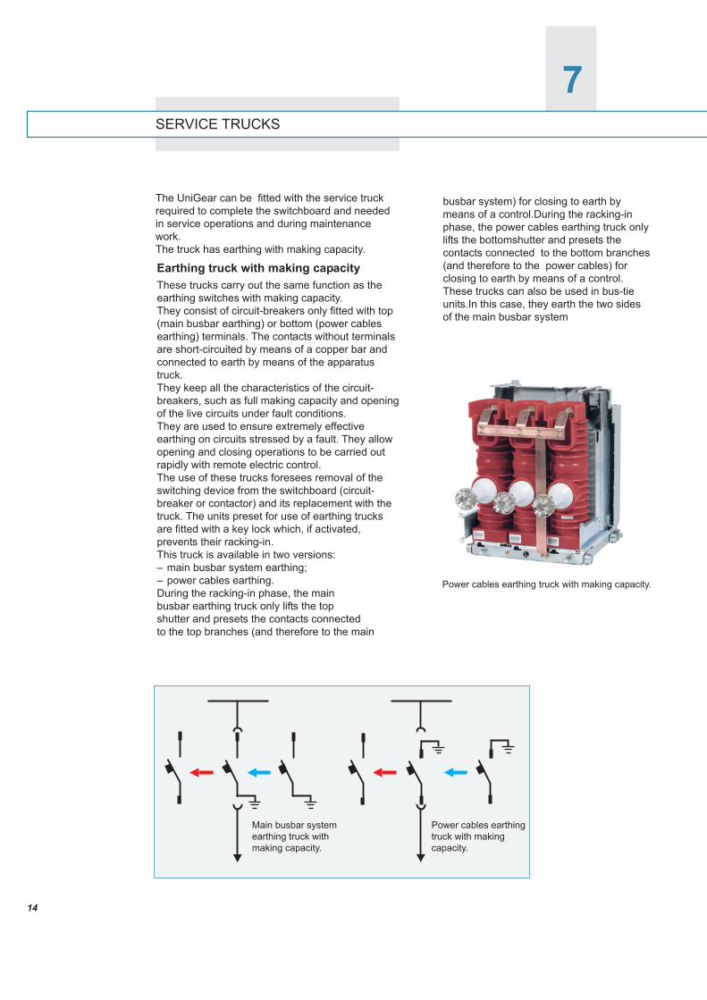
busbar system) for closing to earth bymeans of a control.During the racking-inphase, the power cables earthing truck onlylifts the bottomshutter and presets thecontacts connected to the bottom branches(and therefore to the power cables) forclosing to earth by means of a control.These trucks can also be used in bus-tieunits.In this case, they earth the two sidesof the main busbar system
SERVICE TRUCKS
The UniGear can be fitted with the service truckrequired to complete the switchboard and neededin service operations and during maintenancework.The truck has earthing with making capacity.
Earthing truck with making capacityThese trucks carry out the same function as theearthing switches with making capacity.They consist of circuit-breakers only fitted with top(main busbar earthing) or bottom (power cablesearthing) terminals. The contacts without terminalsare short-circuited by means of a copper bar andconnected to earth by means of the apparatustruck.They keep all the characteristics of the circuit-breakers, such as full making capacity and openingof the live circuits under fault conditions.They are used to ensure extremely effectiveearthing on circuits stressed by a fault. They allowopening and closing operations to be carried outrapidly with remote electric control.The use of these trucks foresees removal of theswitching device from the switchboard (circuit-breaker or contactor) and its replacement with thetruck. The units preset for use of earthing trucksare fitted with a key lock which, if activated,prevents their racking-in.This truck is available in two versions:– main busbar system earthing;– power cables earthing.During the racking-in phase, the mainbusbar earthing truck only lifts the topshutter and presets the contacts connectedto the top branches (and therefore to the main
Power cables earthing truck with making capacity.
Main busbar systemearthing truck withmaking capacity.
Power cables earthingtruck with makingcapacity.
15
8PROTECTION AGAINST INTERNAL ARC
An internal arc is extremely rare in metal-cladswitchboards since the apparatus is manufacturedso as to prevent such an occurrence. Anyway,UniGear ensures maximum personnel safety evenin case of internal arc. The switchboard is built towithstand the overpressures ensuing from theinternal arc and is fitted with ducts to convey theexhausted gases and prevent damage to operatorsand apparatus. The different units are guaranteedarc-proof in compliance with IEC 60298 Standards,enclosure AA, class accessibility A, criteria 1 to 6.
IEC 60298 Standards for internal arc test –Criteria definitions1 The switchboard doors must remain closed
and the covering units must never open up2 Any component that may result hazardous
for the personnel must never be ejected3 The outside enclosure should never get pierced
in the parts accessible to the personnel4 Vertically arranged indicators outside the
switchboard must not get burnt5 Horizontally arranged indicators outside
the switchboard must not get burnt6 All the earthing connectors must remain
effective.
Internal arc test indicators arrangement. Test carried out by means of an infrared camera.
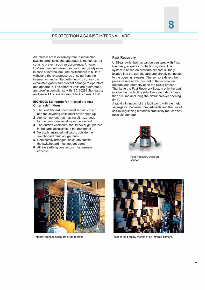
Fast RecoveryUniGear switchboards can be equipped with FastRecovery, a specific protection system. Thissystem is based on pressure sensors suitablylocated into the switchboard and directly connectedto the opening releases. The sensors detect thepressure rise at the moment of the internal arcoutburst and promptly open the circuit breaker.Thanks to the Fast Recovery System only the partinvolved in the fault is selectively excluded in lessthan 100 ms (including the circuit breaker openingtime).A rapid elimination of the fault along with the metalsegregation between compartments and the use ofself-extinguishing materials drastically reduces anypossible damage.
Fast Recovery pressuresensor.
16
9TECHNICAL DATA
ELECTRICAL CHARACTERISTICS
TYPICAL UNITS
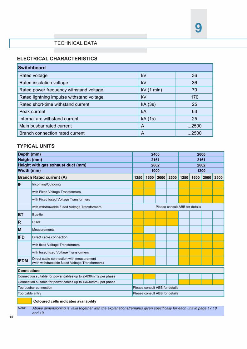
Switchboard Rated voltage kV 36 Rated insulation voltage kV 36 Rated power frequency withstand voltage kV (1 min) 70 Rated lightning impulse withstand voltage kV 170 Rated short-time withstand current kA (3s) 25 Peak current kA 63 Internal arc withstand current kA (1s) 25 Main busbar rated current A ...2500 Branch connection rated current A ...2500
Depth (mm)Height (mm)Height with gas exhaust duct (mm)Width (mm)Branch Rated current (A) 1250 1600 2000 2500 1250 1600 2000 2500
IF Incoming/Outgoing
with Fixed Voltage Transformers
with Fixed fused Voltage Transformers
with withdrawable fused Voltage Transformers
BT Bus-tie
R Riser
M Measurements
IFD Direct cable connection
with fixed Voltage Transformers
with fused fixed Voltage Transformers
IFDM Direct cable connection with measurement (with withdrawable fused Voltage Transformers)
ConnectionsConnection suitable for power cables up to 2x630mm2 per phase
Connection suitable for power cables up to 4x630mm2 per phase
Top busbar connection Please consult ABB for details
Top cable entry Please consult ABB for details
Coloured cells indicates availability
Note: Above dimensioning is valid together with the explanations/remarks given specifically for each unit in page 17,18 and 19.
Please consult ABB for details
1000 1200
240021612662
260021612662
17
10TYPICAL UNITS
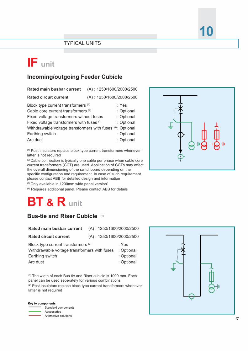
Rated main busbar current (A) : 1250/1600/2000/2500
Rated circuit current (A) : 1250/1600/2000/2500
Block type current transformers (1) : YesCable core current transformers (2) : OptionalFixed voltage transformers without fuses : OptionalFixed voltage transformers with fuses (3) : OptionalWithdrawable voltage transformers with fuses (4) : OptionalEarthing switch : OptionalArc duct : Optional
(1) Post insulators replace block type current transformers wheneverlatter is not required(2) Cable connection is typically one cable per phase when cable corecurrent transformers (CCT) are used. Application of CCTs may effectthe overall dimensioning of the switchboard depending on thespecific configuration and requirement. In case of such requirementplease contact ABB for detailed design and information(3) Only available in 1200mm wide panel version(
(4) Requires additional panel. Please contact ABB for details
IF unitIncoming/outgoing Feeder Cubicle
Rated main busbar current (A) : 1250/1600/2000/2500
Rated circuit current (A) : 1250/1600/2000/2500
Block type current transformers (2) : YesWithdrawable voltage transformers with fuses : OptionalEarthing switch : OptionalArc duct : Optional
(1) The width of each Bus tie and Riser cubicle is 1000 mm. Eachpanel can be used seperately for various combinations(2) Post insulators replace block type current transformers wheneverlatter is not required
BT & R unitBus-tie and Riser Cubicle (1)
Key to componentsStandard componentsAccessoriesAlternative solutions
18
TYPICAL UNITS
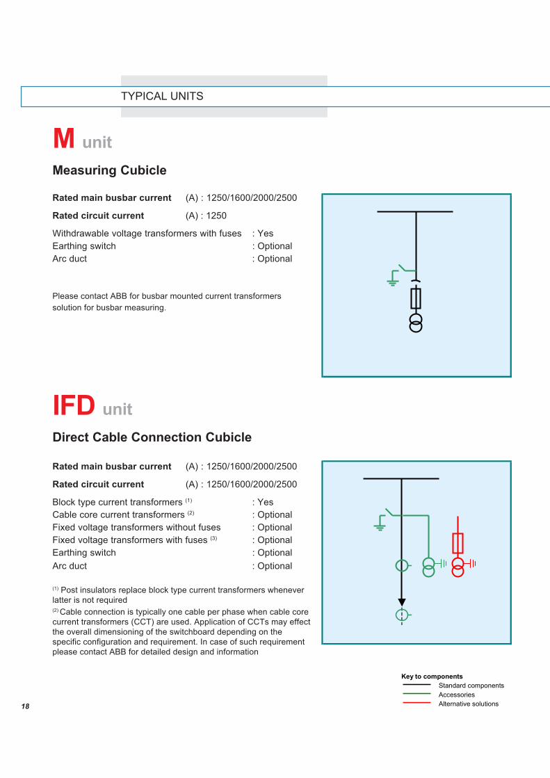
Rated main busbar current (A) : 1250/1600/2000/2500
Rated circuit current (A) : 1250
Withdrawable voltage transformers with fuses : YesEarthing switch : OptionalArc duct : Optional
Please contact ABB for busbar mounted current transformerssolution for busbar measuring.
M unitMeasuring Cubicle
IFD unitDirect Cable Connection Cubicle
Rated main busbar current (A) : 1250/1600/2000/2500
Rated circuit current (A) : 1250/1600/2000/2500
Block type current transformers (1) : YesCable core current transformers (2) : OptionalFixed voltage transformers without fuses : OptionalFixed voltage transformers with fuses (3) : OptionalEarthing switch : OptionalArc duct : Optional
(1) Post insulators replace block type current transformers wheneverlatter is not required(2) Cable connection is typically one cable per phase when cable corecurrent transformers (CCT) are used. Application of CCTs may effectthe overall dimensioning of the switchboard depending on thespecific configuration and requirement. In case of such requirementplease contact ABB for detailed design and information
Key to componentsStandard componentsAccessoriesAlternative solutions
19
TYPICAL UNITS
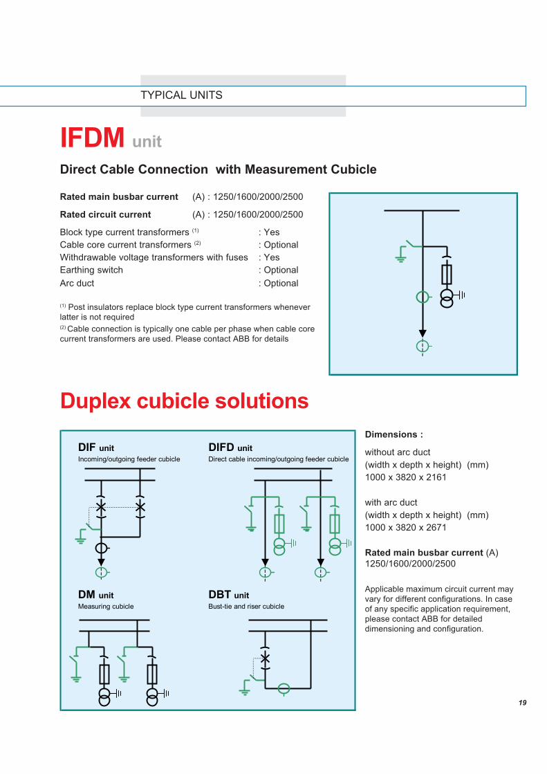
IFDM unitDirect Cable Connection with Measurement Cubicle
Rated main busbar current (A) : 1250/1600/2000/2500
Rated circuit current (A) : 1250/1600/2000/2500
Block type current transformers (1) : YesCable core current transformers (2) : OptionalWithdrawable voltage transformers with fuses : YesEarthing switch : OptionalArc duct : Optional
(1) Post insulators replace block type current transformers wheneverlatter is not required(2) Cable connection is typically one cable per phase when cable corecurrent transformers are used. Please contact ABB for details
Duplex cubicle solutionsDimensions :
without arc duct(width x depth x height) (mm)1000 x 3820 x 2161
with arc duct(width x depth x height) (mm)1000 x 3820 x 2671
Rated main busbar current (A)1250/1600/2000/2500
Applicable maximum circuit current mayvary for different configurations. In caseof any specific application requirement,please contact ABB for detaileddimensioning and configuration.
DIF unitIncoming/outgoing feeder cubicle
DIFD unitDirect cable incoming/outgoing feeder cubicle
DM unitMeasuring cubicle
DBT unitBust-tie and riser cubicle

20
References in 5 continents ...

21

22
23
The
data
and
illu
stra
tions
are
not
bin
ding
. We
rese
rve
the
right
to m
ake
chan
ges
in th
e co
urse
of t
echn
ical
dev
elop
men
t of t
he p
rodu
ct.
1YTS
0300
01-e
n,R
ev-A
, 200
4
ABB Elektrik Sanayi A.S.Organize Sanayi Bölgesi2. Cadde No. 16 Yukari Dudullu34776 Istanbul TurkeyPhone No. : +90 216 528 22 00Fax No. : +90 216 365 29 43e-mail: [email protected] site://www.abb.com


![Unigear Ma_en 1vlm000363 Rev[1].g](https://img.dokumen.tips/doc/110x75/551fa676497959335b8b50af/unigear-maen-1vlm000363-rev1g.jpg)