Embed Size (px)
Citation preview

TRIGEN® IM NAIL SYSTEMSURGICAL TECHNIQUE
Trochanteric Antegrade Nail (TAN™)
As Described ByThomas A. Russell, M.D.
andRoy W. Sanders, M.D.
Nota Bene: The technique description herein is made available to the healthcare professional toillustrate the authors’ suggested treatment for the uncomplicated procedure. In the final analysis,the preferred treatment is that which addresses the needs of the patient.
WARNING: This device is not approved for screw attachment or fixation to the posterior elements (pedicles) of the
cervical, thoracic, or lumbar spine.

PATIENT PREPARATIONPatient is placed supine with unaffected limb
extended below the affected limb and trunk. Theaffected limb is adducted. Flex the affected hip15°–30°. Apply traction through a skeletal pin or thefoot with the fracture table foot holder. Adjust theaffected limb for length and rotation by comparisonwith the unaffected limb. Rotation is further checked by rotating the arm to align the femoral neck antever-sion and then making the appropriate correction byfoot, usually in 0°–15° of external rotation. This is bestchecked by visualizing the femoral anteversion proxi-mally and matching it with correct rotation at the knee(Figure 1A). A second option is illustrated in Figure 1B.
Palpate the greater trochanter. Make a 1 to 3 cmincision proximal to the greater trochanter. Angle thisincision posteriorly at its proximal end. Carry the inci-sion through the fascia (Figure 2).
ENTRY PORTALAssemble the Entry Tool and Honeycomb Insert
(7163-1114). The Entry Tool/Honeycomb assembly isoriented so that the superior side of the bevel is medial(NOTE: this requires setting the Entry Tool indicatorto “R” for a left nail and to “L” for a right nail whichis opposite to the standard FAN technique) andadvanced until it rests against the lateral aspect of thegreater trochanter. Attach suction to the Entry Tool toassist in blood evacuation and minimize aerosolisationof blood to operative team (Figure 3) .
3
2
1
2
TROCHANTERIC ANTEGRADE SURGICAL TECHNIQUE FOR STANDARD FEMORAL OR RECON LOCKING MODES
Figure 1A
Figure 1B
Figure 2
Figure 3

Insert the 3.2 mm tip threaded guide wirethrough the Honeycomb and advance 1 to 2 cm intothe cortex at the tip of the greater trochanter. Theguide wires will snap fit into the Mini-Connector(7163-1186), which easily connects to any drill with a“Hall” connector. Once proper placement of the guidewire has been established, the “honeycomb” insertshould be removed (Figure 4).
Tighten the Entry Reamer Connector (7163-1120)onto the 14 mm Channel Reamer (7163-1118) andinsert the 12.5 mm Entry Reamer (7163-1116) until it “clicks” into the assembly (Figure 5). Attach the12.5 mm Entry Reamer to power to ream the proximalsection of the femur through the Entry Tool. Afterremoving the first guide wire and the Honeycomb, the Channel Reamer assembly is introduced over theremaining wire and advanced 1 to 2 cm into bone. The reamer assembly is then manipulated under imageguidance until the shaft axis and intended path of thereamer form an angle of approximately 5° in the APview and are in line in the ML view. Caution should beused not to overestimate the angle, as too much inser-tion angle of the instrument may make advancementmore difficult. Once the correct orientation is obtained,the reamer assembly is advanced to full depth. Thisreamer assembly enlarges the proximal femur 1.0 mmover the diameter of the head of the nail to 14 mm.Remove the 12.5 mm Entry Reamer and guide wire,keeping the Entry Tool and 14mm Channel Reamer in place (Figure 6).
5
4
3
TROCHANTERIC ANTEGRADE SURGICAL TECHNIQUE FOR STANDARD FEMORAL OR RECON LOCKING MODES
Figure 4
Figure 5
Figure 6
Entry Connector
Channel Reamer 12.5 mm Entry Reamer

FRACTURE REDUCTIONSnap the T-Handle (7163-1172) onto the
Reducer (7163-1124) (Figure 7) . Place these throughthe Entry Tool and 14 mm Channel Reamer to reducethe fracture (Figure 8) . Once the Reducer is in themedullary canal and has captured the distal fragment,the 3.0 mm Ball-Tipped Guide Rod (7163-1126) isinserted through the Reducer into the distal femur in the region of the epiphyseal scar (Figure 9) . The Gripper (7163-1100) is useful in holding onto the Guide Rod during insertion and removal(Figure 9 Inset).
6
4
TROCHANTERIC ANTEGRADE SURGICAL TECHNIQUE FOR STANDARD FEMORAL OR RECON LOCKING MODES
Figure 7
Figure 8
Figure 9
Figure 9 Inset

CANAL PREPARATIONCanal preparation is dependent on surgical deci-
sion. If reaming is planned, use progressive reamersthrough the Entry Tool. Unreamed nails are selectedbased on preoperative planning, but should be of suffi-cient size to provide translational fill of the intramedul-lary canal in the mid-diaphysis. Once the Guide Rod is in place, remove the Reducer but leave the 14 mmChannel Reamer in place. Proceed to sequentially ream the femoral shaft to .5 to 1.0 mm or more abovethe chosen nail diameter through the 14 mm ChannelReamer. For more curved femoral shafts, .5 to 1.0 mmof over reaming may be beneficial (Figure 10). Inpatients that are very tall, the Flex Reamer Extender(7163-1130) may be added to extend the shaft of theflexible reamer for very distal fractures or nails longerthan 42 cm. NOTE: For 13 mm nails, the 14 mmChannel Reamer must be removed before reamingwith the 13.5 and 14 mm reamer diameters .
NAIL SELECTIONDetermine nail diameter from image intensifier or
templating. Never insert a nail that has a larger diameterthan the last reamer used.
Position the tip of the guide rod at the desired levelof the tip of the nail considering fracture patterns andlocking screw positioning (Figure 11) . Measure the nail length by positioning the open end of the Ruler(7163-1128) over the exposed end of the guide rodpushing the end down to the level of bone through the14 mm Channel Reamer. Confirm the position on theimage intensifier. The tip of the Ruler should line upwith the step on the 14 mm Channel Reamer for correctlength measurement. The end should be at the tip of thepiriforma fossa for the TAN Recon mode. Use preoptemplating for correct length measurement, as excessivecountersinking may require as much as a 2 cm shorternail length adjustment. Read the nail length from thecalibrations exposed at the other end of the Ruler. Leave the guide rod in place for placement of the nail.Exchange of the ball-tipped guide rod is not necessary.
9
8
7
5
TROCHANTERIC ANTEGRADE SURGICAL TECHNIQUE FOR STANDARD FEMORAL OR RECON LOCKING MODES
Figure 10
Figure 11

DRILL GUIDE ASSEMBLYFEMORAL MODE
Insert the Guide Bolt (7163-1136) into the DrillGuide (7163-1134) and use the Guide Bolt Wrench(7163-1140) to secure the bolt to the nail. Screw theImpactor onto the top of the Drill Guide to drive thenail into the medullary canal (Figure 12) . Insert theSkin Protector (7163-1132) in the incision parallel tothe Entry Reamer Tool. Remove the Entry Reamer Tooland 14 mm Channel Reamer. The Skin Protector willassist in maintaining control of the surrounding tissuesand provide continued access to the bone. Advance the nail over the guide rod and carefully past thefracture. As the nail is inserted, it is rotated so the bowis pointed lateral. During advancement, the nail maybe rotated to allow proper positioning and seating ofthe proximal section if needed. Due to the greatertrochanter entry point, it may be necessary to counter-sink the nail more than a FAN to ensure the proximallocking screws are positioned appropriately. At thispoint the standard FAN technique may be followed.Remove the guide rod after the nail is inserted andbefore inserting the locking screws (Figure 13) .
INTERLOCKING FOR FEMORAL MODE
Proximal Screw: To place screws at a 45° anglefrom the greater to lesser trochanter, the followingoptions are available (Figure 14):
A. PREDRILLING TECHNIQUE — Make a stab inci-sion at the entry hole and push the Gold Outer DrillSleeve (7163-1152) through the drill guide holeuntil it is touching the lateral cortex. Introduce theSilver Inner Drill Sleeve (7163-1156) through theGold Outer Drill Sleeve. Attach the Long Pilot Drill(7163-1110) to power using the Mini-Connector(7163-1186). The length measurements are taken
11
10
6
TROCHANTERIC ANTEGRADE SURGICAL TECHNIQUE FOR STANDARD FEMORAL OR RECON LOCKING MODES
Figure 13
Figure 14
5.0 mm (GOLD) screws are to be used to lock the 10 mm,11.5 mm and 13 mm TAN Implants.
Figure 12
Lime = LeftRose = Right

from the calibrations off the drill in relation to theend of the Silver Inner Drill Sleeve (Figure 15) . The appropriate length 5.0 mm screw (GOLD) isselected and attached to the Screwdriver. The drilland Silver Inner Drill Sleeve are removed and thescrew is inserted through the Gold Outer DrillSleeve. Attach Screwdriver to power or use manualT-Handle (7163-1172) and place screw in bone. TheScrewdriver contains a laser-marked ring. This ringshould be stopped short of the Gold Outer DrillSleeve to prevent final seating of the screw by power.It is recommended that final tightening of the 5.0 mm screw should always be under manual con-trol using the T-Handle (7163-1172) (Figure 16).
B. SCREW LENGTH GAUGE — Pre-drill through bothcortices. Insert the Screw Length Gauge through theGold Outer Drill Sleeve (7163-1152) from the farcortex to measure for proper 5.0 mm screw (GOLD)length. The appropriate length 5.0 mm screw(GOLD) is selected and attached to the Screwdriver(Figure 17) . Attach Screwdriver handle to power oruse manual T-handle (7163-1172) and place screwsin bone. The Screwdriver contains a laser-markedring. This ring should be stopped short of the 9 mmDrill Sleeve to prevent final seating of the screw bypower. It is recommended that final tightening ofthe 5.0 mm screw should always be under manualcontrol using the T-Handle (7163-1172) (Figures 18 and 19) .
7
TROCHANTERIC ANTEGRADE SURGICAL TECHNIQUE FOR STANDARD FEMORAL OR RECON LOCKING MODES
Figure 15
Figure 17
Figure 18
Figure 19
Figure 16

DRILL GUIDE ASSEMBLYRECON MODE (Also Applies to Trochanteric Nail)
6.4 mm (BLUE) screws are to be used to lock the 10 mm,11.5 mm and 13 mm diameter TAN Implants proximally in the Recon mode.
Insert the Guide Bolt (7163-1136) into the DrillGuide (7163-1134) and use the Guide Bolt Wrench(7163-1140) to secure the bolt to the nail. Connect the Hip Guide (7163-1144) to the Drill Guide. Theguide is keyed so that it will only fit one way. Tightenthe knurled knob by hand until snug. Use the end ofthe Guide Bolt Wrench (7163-1140) to finish tighteningthe guide in place. Check the alignment of the guide to the screw holes by passing the Medium Screwdriver(7163-1166) through the Gold Outer Drill Sleeve(7163-1152) up into the holes of the nail. Screw theImpactor onto the top of the Drill Guide to drive thenail into the medullary canal (Figure 19) . Insert theSkin Protector (7163-1132) in the incision parallel tothe Entry Reamer Tool. Remove the Entry Reamer Tooland Channel Reamer. The Skin Protector will assist inmaintaining control of the surrounding tissues andprovide continued access to the bone. Advance the nail over the guide rod and carefully past the fracture.Remove the guide rod after the nail is inserted andbefore inserting the locking screws (Figure 20). Ifinsertion is difficult, place the bow of the nail lateral androtate during insertion to more easily place the nail.
10
8
TROCHANTERIC ANTEGRADE SURGICAL TECHNIQUE FOR STANDARD FEMORAL OR RECON LOCKING MODES
Figure 19
Figure 20
5.0 mm (GOLD) screws are to be used to distal lock 10.5 mm, 11 mm and 13 mm TAN Implants.

INTERLOCKING FOR RECON MODEPROXIMAL SCREWS: Two aspects of screw place-
ment into the femoral head must be noted beforedrilling into the femoral head. (1) Alignment of theanteversion, and (2) Depth of nail insertion. To begin,rotate the C-Arm proximally until a true line of the hipis visualized, this gives the correct axis of alignment foranteversion. Rotate the handle of the nail guide until itbisects the femoral head in the lateral view. Thisshould assist in setting the correct anteversion positionof the screws. Mark this position with a skin marker onthe leg parallel to the driving handle. Next, rotate theC-Arm into an A/P view using the calibrated notches onthe proximal attachment of the nail, which is visualizedradiographically, to determine from preoperative plan-ning what depth of nail insertion will be required toallow both screws to be centered in the head. As a rule,the inferior screw is placed first, though in situationswhere the neck is large enough, the proximal screwcan be placed, again, approximately 4-5 mm from thesuperior cortical margin of the femoral neck. Thesescrews are angled at 135° in relation to the shaft. Ifboth screws will not seat within the femoral head, it isprobable that too much varus positioning of the proxi-mal fragment has occurred, or the proximal nail entryportal is too lateral (Figure 21) .
A. 6.4 mm Screw Placement Technique — Makean incision at the entry holes of the proximal screwsleeves, and then connect the two puncture woundsfor approximately a 3 cm incision that will accom-modate the insertion of both screws. Insert theSilver Inner Drill Sleeve (1163-1156) into the GoldOuter Drill Sleeve (7163-1152) and push to bone.Insert the Tip Threaded Guide Pin (7163-1190) intothe Silver Inner Drill Sleeve (7163-1152) and con-nect to power using the Mini-Connector (7163-1186). Drill into the femoral neck and head to thedesired depth and position (Figure 22) . Drill the
11
9
TROCHANTERIC ANTEGRADE SURGICAL TECHNIQUE FOR STANDARD FEMORAL OR RECON LOCKING MODES
Figure 22
Figure 21
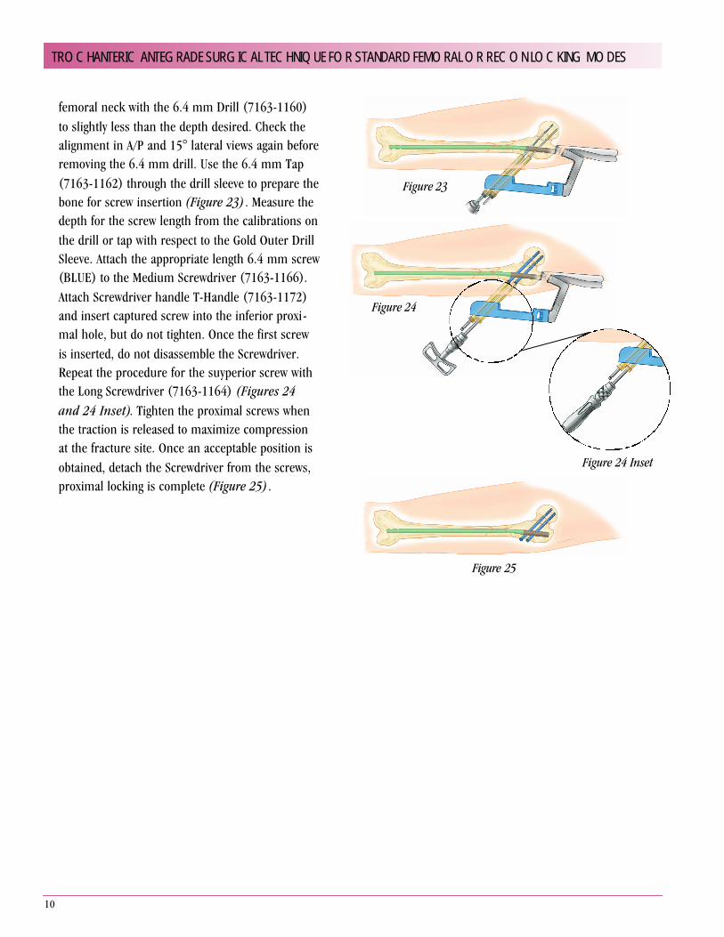
femoral neck with the 6.4 mm Drill (7163-1160)to slightly less than the depth desired. Check thealignment in A/P and 15° lateral views again beforeremoving the 6.4 mm drill. Use the 6.4 mm Tap(7163-1162) through the drill sleeve to prepare thebone for screw insertion (Figure 23) . Measure thedepth for the screw length from the calibrations onthe drill or tap with respect to the Gold Outer DrillSleeve. Attach the appropriate length 6.4 mm screw(BLUE) to the Medium Screwdriver (7163-1166).Attach Screwdriver handle T-Handle (7163-1172)and insert captured screw into the inferior proxi-mal hole, but do not tighten. Once the first screwis inserted, do not disassemble the Screwdriver.Repeat the procedure for the suyperior screw withthe Long Screwdriver (7163-1164) (Figures 24and 24 Inset). Tighten the proximal screws whenthe traction is released to maximize compressionat the fracture site. Once an acceptable position isobtained, detach the Screwdriver from the screws,proximal locking is complete (Figure 25) .
10
TROCHANTERIC ANTEGRADE SURGICAL TECHNIQUE FOR STANDARD FEMORAL OR RECON LOCKING MODES
Figure 23
Figure 24
Figure 24 Inset
Figure 25

DISTAL SCREWS FOR STANDARD TAN: Perform distallocking with the standard TAN with the Cole Radiolucent Drill or Freehand Technique. The Freehand technique is used with the C-Arm placed medial to the patient, allowing for properimage of the femur. Make adjustments to the C-Arm until perfect circles are visualized. For the short TAN (Blue), distal locking is performed by attaching the 8.5 mm FAN Guide (7163-1119)with the Blue Tip for targeting the distal holes. Make a stabincision over the holes of the image and then one of the following techniques may be used (Figure 26) .
A. Predrilling Technique — After perfect circles are con-firmed, a stab incision is made over the holes. Confirm thealignment and attach the Long Drill (7163-1110) to powerusing the Mini-Connector (7163-1186). Insert the drillthrough both cortices. Remove the Mini-Connector and pushthe Silver Inner Drill Sleeve (7163-1156) to bone over thedrill. The length measurements are taken from the calibra-tions off the drill in relation the Silver Inner Drill Sleeve tobone (Figure 27) . The appropriate length screw is selectedand attached to the Screwdriver. Remove the Drill and SilverInner Drill Sleeve. Attach Screwdriver handle to power or use manual T-handle (7163-1172) and place screws in bone. It is recommended that final tightening of the screwshould always be under manual control using the T-Handle(7163-1172) (Figure 28).
12
11
TROCHANTERIC ANTEGRADE SURGICAL TECHNIQUE FOR STANDARD FEMORAL OR RECON LOCKING MODES
Figure 27
Figure 26
Figure 28
Proper Screw Measurement
ä All TriGen locking screw measuring devices,measure from bottom of head to the last complete thread of screw. This is the workinglength of the screw. Thus, the screw itself is longer than the measurement and adding length is not necessary.

12
TROCHANTERIC ANTEGRADE SURGICAL TECHNIQUE FOR STANDARD FEMORAL OR RECON LOCKING MODES
Figure 32
B. Screw Length Gauge — Predrill through both cor-tices. Insert the Gold Outer Drill Sleeve (7163-1152)to bone. Insert the Screw Length Gauge through theGold Outer Drill Sleeve from the far cortex to measurefor proper screw length (Figure 29) . The appropriatelength screw is selected and attached to theScrewdriver. Attach Screwdriver handle to power oruse manual T-handle (7163-1172) and place screwsin bone (Figure 30) . It is recommended that finaltightening of the screw should always be undermanual control using the T-Handle (7163-1172) .
C. (Optional) Power Technique — The distal inter-locking technique can be performed without a guideby the freehand method. This can be done by placingthe Ruler (7163-1128) on top of the leg and taking aC-arm image. Count the number of grooves betweenthe edge of the Ruler and the far cortex. The groovesare 5 mm apart. The Ruler should be placed againstthe edge of the near cortex for the best measurement.The screw length should be adjusted 3-5 mm longerfor magnification error correction to ensure that thefar cortex is reached. The proper length screw isattached to the Screwdriver. After “perfect circles” are confirmed, insert the screw into bone through the Gold Outer Drill Sleeve (7163-1152) using power.The Screwdriver contains a laser-marked ring. Thisring should be stopped short of the Gold Outer DrillSleeve to prevent final seating of the screw by power. It is recommended that final tightening of the screwshould always be under manual control using the T-Handle (7163-1172) (Figure 31).
D. Targeter — The Targeter (7163-1174) may be usedto assist in placing additional distal screws after thefirst screw has been inserted (Figure 32) . Be sure to use the Medium Screwdriver (7163-1166) whenplacing the first screw in bone as outlined in theabove options. Leave the Medium Screwdriverattached to the first screw in the bone. Choosewhether you will be “statically” or “dynamically”
Figure 31
Figure 29
Figure 30

locking the implant. Place the appropriate labeledhole on the Targeter over the Screwdriver and pushto skin. Making sure that the Targeter can freelyrotate. The Short Screwdriver (7163-1168) can alsobe attached to the side of the Targeter. It acts as ahandle to stabilize the Targeter as well as an aid inreducing exposure of the hand during imaging. Usethe C-Arm to rotationally locate the second hole.Once the position is found, place the Short Drill(7163-1112) through the wire hole on the Targeterand into bone to maintain position. The Mini-Connector (7163-1186) provides a convenientattachment of the drill to power. Make an incision atthe tip of the barrel for the second screw and insertthe Silver Inner Drill Sleeve and Targeter to bone.Use of the standard pre-drill technique or powertechnique can be used to finish screw placement(Figure 33) . The optional power technique can alsobe used for the second screw by removing the SilverInner Drill Sleeve (Figure 34) .
DISTAL SCREWS FOR SHORT TAN (BLUE): Forthe short TAN, distal locking is performed by attachingthe 8.5 mm Grey FAN Guide (7163-1119) with the BlueTip. The blue tip is designed to provide guided targetingof the distal screw holes in the Short TAN implants(Figure 35) .
CLOSUREOn completion of the procedure, the proximal
guide is removed with the Guide Bolt Wrench (7163-1140), wounds are irrigated and closed in a standard fashion (Figures 36, 37 and 38).
14
13
13
TROCHANTERIC ANTEGRADE SURGICAL TECHNIQUE FOR STANDARD FEMORAL OR RECON LOCKING MODES
Figure 34
Figure 37
Figure 38
Figure 33
Figure 35
Figure 36

14
SURGICAL TECHNIQUE FOR TRIGEN NAIL CAPS WITH TAN
TriGen Nail Caps are available in 5 mm (7163-3005), 10 mm (7163-3010), 15 mm (7163-3015) and 20 mm(7163-3020) sizes to accommodate most countersinkingneeds. The cap length includes the external driving hex.
ASSEMBLY AND PLACEMENT WITH FAN1. The proper cap is chosen based on the amount of
countersinking measured on preoperative templates orfrom the drill guide countersinking measurements.
2. It is recommended that the polyethylene plug beremoved in nail caps being used for TrochantericAntegrade Nails. Removing the plug allows for easierremoval using a guided approach if the nail has to be removed. Use the Obturator (7163-1122) to press on and expel the polyethylene plug located inside the nail cap.
3. After removal of the plug, attach the nail cap to theLong Captured Screwdriver (7163-1164).
4. Insert the nail cap through the incision and tighten it to the nail. Be sure to properly align the nail cap to thenail to prevent cross threading. Some resistance may be felt. This is due to a pennig process to the threadsdesigned to minimize backout.
5. Reconfirm that the nail cap is properly located all the way down to the nail.
6. Disconnect the Captured Screwdriver.
REMOVAL OF NAIL CAPThe TriGen Nail Cap was designed to allow for a percuta-neous and captured approach when removing from anAntegrade Nail as follows:
1. Make a 1 cm to 2 cm incision in approximately thesame location as the original incision used to place the nail.
2. Locate the nail cap.
3. Place a 3.2 mm Guide Wire (7163-1190) into thecannulation of the nail cap.
4. Place the 12.5 mm Entry Reamer (7163-1116) downto the nail cap and use to clear debris.
5. Remove the retaining shaft from the Long CapturedScrewdriver (7163-1164).
6. Attached the T-Handle (7163-1172) to the screwdriver(7163-1164).
7. Place the screwdriver over the 3.2 mm Guide Wire(7163-1190) and secure to the external hex of the nail cap.
8. Remove the guide wire.
9. Remove the T-Handle and replace the retaining shaftback inside the screwdriver.
10. Reattach T-Handle and secure the capturedscrewdriver to the nail cap.
11. Remove the nail cap.
NAIL CAPSCat. No. Length7163-3005 5 m m7163-3010 10 mm7163-3015 15 mm7163-3020 20 mm

15
SURGICAL TECHNIQUE FOR NAIL EXTRACTION
The TriGen Instrument Set offers two extractors for nailexplanation. When removing a TriGen nail, the LargeExtractor (7163-1178) is always used. For nails otherthan TriGen, the Large Extractor is designed to removediameters greater than 10 mm. The Small Nail Extractor(7163-1176) is designed for 10 mm diameters or smallernails. These two nail extractors are designed to removevirtually any nail.
STANDARD TECHNIQUE FOR LARGE OR SMALL EXTRACTORStandard Technique for Large or Small Extractor
1. Patient is placed in correct position on a radiolucenttable for imaging.
2. Make a 1 cm to 2 cm incision in approximately thesame location as the original incision used to place the nail.
3. Place the 3.2 mm Tip Threaded Guide Wire (7163-1190) into the top of the nail.
4. Insert the 12.5 mm Entry Reamer (7163-1116) to thetop of the nail and use to clear debris and overgrowth.
5. After debris has been cleared, remove the guide wireand Entry Reamer and assemble the Impactor to theappropriate extractor.
6. The extractor is placed through the incision down tothe top of the nail and screwed into the nail usingslight, downward pressure. Be sure to check alignmentof the extractor and nail to make assembly easier.
7. After the Extractor is tightened to the nail, the GuideBolt Wrench (7163-1140) is placed into the hole on the Impactor (7163-1185) handle to provide additional leverage.
8. Remove all locking screws.
9. The Slotted Hammer (7163-1150) is then placed on the Impactor and used to back slap the nail out of the bone.
OPTIONAL CANNULATED TECHNIQUEFOR LARGE EXTRACTOR ONLYMOST USEFUL WHEN REMOVING ANTEGRADE FEMORAL NAILS
1. Patient is placed lateral decubitus on a radiolucenttable for imaging.
2. Make a 1 cm to 2 cm incision in approximately thesame location as the original incision used to placethe nail.
3. Place the 3.2 mm Tip Threaded Guide Wire (7163-1190) into the top of the nail.
4. Insert the 12.5 mm Entry Reamer (7163-1116) overthe guide wire to the top of the nail and use to cleardebris and overgrowth.
5. Once the debris is cleared, remove the Entry Reamer,leaving the 3.2 mm Tip Threaded Guide Wire inplace.
6. Assemble the One-Piece Impactor (7163-1185) to the Large Extractor.
7. The Large Extractor is placed over the wire andguided to the top of the nail. The Extractor is screwedinto the nail using slight downward pressure.
8. After the extractor is tightened to the nail, the GuideBolt Wrench (7163-1140) is placed into the hole onthe Impactor (7163-1185) handle to provide addi-tional leverage.
9. Remove all locking screws.
10. The Slotted Hammer (7163-1150) is then placed on the hammer and used to back slap the nail and 3.2 mm guide wire out of the bone.

16
17
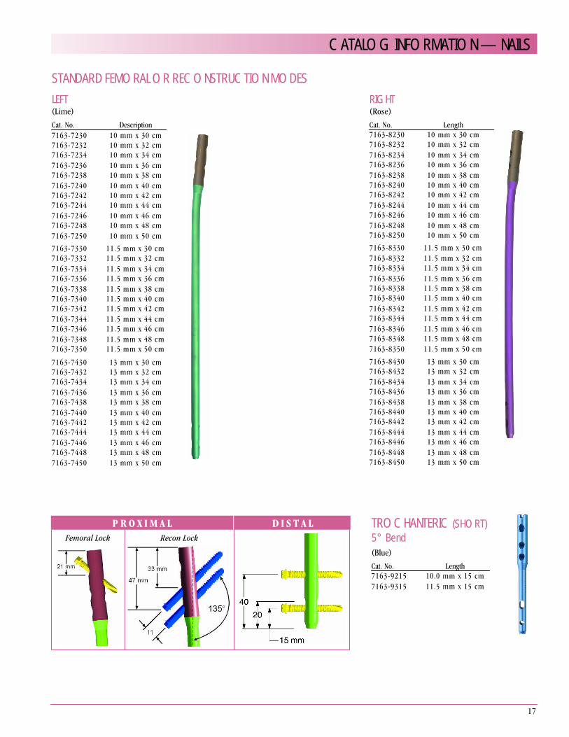
STANDARD FEMORAL OR RECONSTRUCTION MODESLEFT(Lime)Cat. No. Description7163-7230 10 mm x 30 cm7163-7232 10 mm x 32 cm7163-7234 10 mm x 34 cm7163-7236 10 mm x 36 cm7163-7238 10 mm x 38 cm7163-7240 10 mm x 40 cm7163-7242 10 mm x 42 cm7163-7244 10 mm x 44 cm7163-7246 10 mm x 46 cm7163-7248 10 mm x 48 cm7163-7250 10 mm x 50 cm7163-7330 11.5 mm x 30 cm7163-7332 11.5 mm x 32 cm7163-7334 11.5 mm x 34 cm7163-7336 11.5 mm x 36 cm7163-7338 11.5 mm x 38 cm7163-7340 11.5 mm x 40 cm7163-7342 11.5 mm x 42 cm7163-7344 11.5 mm x 44 cm7163-7346 11.5 mm x 46 cm7163-7348 11.5 mm x 48 cm7163-7350 11.5 mm x 50 cm
7163-7430 13 mm x 30 cm7163-7432 13 mm x 32 cm7163-7434 13 mm x 34 cm7163-7436 13 mm x 36 cm7163-7438 13 mm x 38 cm7163-7440 13 mm x 40 cm7163-7442 13 mm x 42 cm7163-7444 13 mm x 44 cm7163-7446 13 mm x 46 cm7163-7448 13 mm x 48 cm7163-7450 13 mm x 50 cm
RIGHT(Rose)Cat. No. Length7163-8230 10 mm x 30 cm7163-8232 10 mm x 32 cm7163-8234 10 mm x 34 cm7163-8236 10 mm x 36 cm7163-8238 10 mm x 38 cm7163-8240 10 mm x 40 cm7163-8242 10 mm x 42 cm7163-8244 10 mm x 44 cm7163-8246 10 mm x 46 cm7163-8248 10 mm x 48 cm7163-8250 10 mm x 50 cm7163-8330 11.5 mm x 30 cm7163-8332 11.5 mm x 32 cm7163-8334 11.5 mm x 34 cm7163-8336 11.5 mm x 36 cm7163-8338 11.5 mm x 38 cm7163-8340 11.5 mm x 40 cm7163-8342 11.5 mm x 42 cm7163-8344 11.5 mm x 44 cm7163-8346 11.5 mm x 46 cm7163-8348 11.5 mm x 48 cm7163-8350 11.5 mm x 50 cm7163-8430 13 mm x 30 cm7163-8432 13 mm x 32 cm7163-8434 13 mm x 34 cm7163-8436 13 mm x 36 cm7163-8438 13 mm x 38 cm7163-8440 13 mm x 40 cm7163-8442 13 mm x 42 cm7163-8444 13 mm x 44 cm7163-8446 13 mm x 46 cm7163-8448 13 mm x 48 cm7163-8450 13 mm x 50 cm
TROCHANTERIC (SHORT)5° Bend(Blue)Cat. No. Length7163-9215 10.0 mm x 15 cm7163-9315 11.5 mm x 15 cm
CATALOG INFORMATION — NAILS
P R O X I M A L D I S T A LFemoral Lock Recon Lock

18
5.0 MM CAPTURED SCREW(Gold) For 10 mm, 11.5 mm & 13 mm ImplantsCat. No. Length7163-2220 20 mm7163-2225 25 mm7163-2230 30 mm7163-2235 35 mm7163-2240 40 mm7163-2245 45 mm7163-2250 50 mm7163-2255 55 mm7163-2260 60 mm7163-2265 65 mm7163-2270 70 mm7163-2275 75 mm7163-2280 80 mm7163-2285 85 mm 7163-2290 90 mm 7163-2295 95 mm7163-2200 100 mm7163-2205 105 mm 7163-2210 110 mm
6.4 MM CAPTURED RECON SCREW(Blue)Cat. No. Length7163-2365 65 mm7163-2370 70 mm7163-2375 75 mm7163-2380 80 mm 7163-2385 85 mm7163-2390 90 mm7163-2395 95 mm7163-2300 100 mm7163-2305 105 mm7163-2310 110 mm 7163-2316* 115 mm7163-2320 120 mm7163-2325 125 mm
CATALOG INFORMATION — SCREWS/NAIL CAPS
NAIL CAPSCat. No. Length7163-3005 5 mm7163-3010 10 mm7163-3015 15 mm7163-3020 20 mm

19
GripperCat. No. 7163-1100
Long Pilot DrillCat. No. 7163-1110
Short Pilot DrillCat. No. 7163-1117
Entry ToolCat. No. 7163-1114
12.5 mm Entry ReamerCat. No. 7163-1116
14 mm Channel ReamerCat. No. 7163-1118
Entry Reamer ConnectorCat. No. 7163-1120
ObturatorCat. No. 7163-1122
ReducerCat. No. 7163-1124
3.0 mm X 1000 mm Ball Tip Guide RodCat. No. 7163-1126
RulerCat. No. 7163-1128
Flex Reamer ExtenderCat. No. 7163-1130
Skin ProtectorCat. No. 7163-1132
CATALOG INFORMATION — INSTRUMENTATION

20
Drill GuideCat. No. 7163-1134
Guide BoltCat. No. 7163-1136
Quick BoltCat. No. 7163-1138
Guide Bolt WrenchCat. No. 7163-1140
Knee GuideCat. No. 7163-1142
Hip GuideCat. No. 7163-1144
8.5 mm FAN GuideCat. No. 7163-1119
One Piece ImpactorCat. No. 7163-1185
HammerCat. No. 7163-1150
Gold Outer Drill SleeveCat. No. 7163-1152
Silver Inner Drill SleeveCat. No. 7163-1156
Supracondylar GuideCat. No. 7163-1158
6.4 mm DrillCat. No. 7163-1160
6.4 mm TapCat. No. 7163-1162
CATALOG INFORMATION — INSTRUMENTATION

21
Long ScrewdriverCat. No. 7163-1164
Medium ScrewdriverCat. No. 7163-1166
Short ScrewdriverCat. No. 7163-1168
Screwdriver Replacement BarsCat. No. Description7163-1165 Large7163-1167 Medium7163-1169 Short
Screw Length GaugeCat. No. 7163-1170
Direct Measuring GaugeCat. No. 7163-1189
T-Handle (Zimmer-Hall)Cat. No. 7163-1172
Straight Screwdriver HandleCat. No. 7163-1163
TargeterCat. No. 7163-1174
Small ExtractorCat. No. 7163-1176
Large ExtractorCat. No. 7163-1178
Small AO AdapterCat. No. 7163-1184
Trinkle AdapterCat. No. 7163-1183
CATALOG INFORMATION — INSTRUMENTATION

22
Mini ConnectorCat. No. 7163-1186
Trinkle Mini ConnectorCat. No. 7163-1187
Tip Threaded Guide WireCat. No. 7163-1190
Flex Reamer ShaftCat. No. 7163-1192
Screwdriver Release HandleCat. No. 7163-1208
Pilot Nose Reamer HeadsCat. No. Description7111-8233 9.5 mm Head7111-8234 10.0 mm Head7111-8235 10.5 mm Head7111-8236 11.0 mm Head7111-8237 11.5 mm Head7111-8238 12.0 mm Head7111-8239 12.5 mm Head7111-8240 13.0 mm Head7111-8241 13.5 mm Head7111-8242 14.0 mm Head
Modular Reamer BoxCat. No. 7163-1218
CATALOG INFORMATION — INSTRUMENTATION

23
Instrument Case SetCat. No. 7163-1200Consists of: 7112-9400 Large Outer Case; 7112-9402 Lid for OuterCase; 7163-1199; and 7163-1201
TriGen Instrument Tray 1Cat. No. 7163-1199
TriGen Instrument Tray 2Cat. No. 7163-1201
FAN Case – LeftCat. No. 7163-1202
FAN Case – RightCat. No. 7163-1203
Knee Nail CaseCat. No. 7163-1204
FAN Case – 13 mm NailsCat. No. 7163-1206
Screw CaddyCat. No. 7163-1180
Large Outer Case 4.8”Cat. No. 7112-9400
Small Outer Case 2.4”Not ShownCat. No. 7112-9401
Lid for Outer CaseShown with CaseCat. No. 7112-9402
CATALOG INFORMATION — INSTRUMENTATION/IMPLANT TRAYS

24
IMPORTANT MEDICAL INFORMATIONINTRAMEDULLARY NAIL SYSTEM
SPECIAL NOTE
The Intramedullary Nail System consists of interlocking intramedullary nails, and inter-locking fusion nails, and pins. Intramedullary nails contain holes proximally and distallyto accept locking screws. Components are available in many styles and sizes and aremanufactured from various types of metals. The component material is provided on theoutside carton label. Use only components made from the same material together. Donot mix dissimilar metals or components from different manufacturers. Refer to manu-facturer literature for specific product information. All implantable devices are designedfor single use only.
Intramedullary Interlocking Nails are provided with a variety of screw placement optionsbased on surgical approach, antegrade or retrograde, and indications.
Interlocking Fusion Nails indicated for joint arthrodesis have screw holes for locking oneither side of the joint being fused. The locking screws reduce the likelihood of shorten-ing and rotation of the fusion site.
INDICATIONS
The general principles of patient selection and sound surgical judgment apply to theintramedullary nailing procedure. The size and shape of the long bones present limitingrestrictions on the size and strength of implants.
Indications for interlocking intramedullary nails include simple long bone fractures;severely co mminuted, spiral, large oblique and segmental fractures; nonunions andmalunions; polytrauma and multiple fractures; prophylactic nailing of impending patho-logic fractures; reconstruction, following tumor resection and grafting; supracondylarfractures; bone lengthening and shortening. Interlocking intramedullary nails are indi-cated for fixation of fractures that occur in and between the proximal and distal third ofthe long bones being treated.
In addition to the indications for interlocking intramedullary nails, devices that containholes/slots proximally to accept screws that thread into the femoral head for compres-sion and rotational stability are indicated for the following: subtrochanteric fractures withlesser trochanteric involvement; ipsilateral femoral shaft/neck fractures; andintertrochanteric fractures.
In addition to the indications for interlocking intramedullary nails, devices that utilize aretrograde femoral surgical approach are indicated for the following: severely co mmin-uted supracondylar fractures with or without difficult intra-articular extension; fracturesthat require opening the knee joint to stabilize the femoral condylar segment; fracturesabove total knee implants.
Indications for the Knee Nail include the following: degeneration, deformity, or trauma ofboth the tibiotalar and talocalcaneal articulations in the hindfoot; tibiocalcaneal arthrode-sis; combined arthrodesis of the ankle and sub-talar joints; avascular necrosis of theankle and sub-talar joints; failed total ankle replacement with sub-talar intrusion; failedankle arthrodesis with insufficient talar body; rheumatoid arthritis; severe deformity sec-ondary to untreated talipes equinovarus or neuromuscular disease; and severe pilonfractures with trauma to the sub-talar joint.
Knee Fusion Nails are intended for intramedullary knee arthrodesis.
CONTRAINDICATIONS
1. These systems should not be used in crossing open epiphyseal plates.
2. Insufficient quantity or quality of bone, obliterated medullary canal or conditions whichtend to retard healing, also, blood supply limitations, previous infections, etc.
3. Active infection.
4. The presence of a previously inserted fracture fixation device.
5. Preexisting bone deformity.
6. Hypovolemia, hypothermia and coagulopathy.
7. Mental conditions that preclude cooperation with the rehabilitation regimen.
8. The forearm nail should not be used in children who have not reached skeletalmaturity.
WARNINGS
1. This device is not approved for screw attachment or fixation to the posterior elements(pedicles) of the cervical, thoracic, or lumbar spine.
2. Intramedullary nails are neither intended to carry the full load of the patient acutely,nor intended to carry a significant portion of the load for extended periods of time.
3. The correct selection of device components is extremely important. The appropriatetype and size should be selected for the patient. Failure to use the largest possiblecomponents or improper positioning may result in loosening, bending, cracking, orfracture of the device or bone or both.
4. Do not mix dissimilar metals. Use only stainless steel screws with stainless steeldevices, and Ti-6A1-4V screws with Ti-6A1-4V devices.
PRECAUTIONS
1. Use care in handling and storage of implant components. Cutting, sharply bending orscratching the surface can significantly reduce the strength and fatigue resistance ofthe implant system. This, in turn, could induce cracks and/or noninternal stresses thatcould lead to fracture of the implants.
2. Surgical technique information is available upon request. The surgeon should befamiliar with the devices, instruments and surgical technique prior to surgery.
3. The use of locking screws is necessary for strength and compatibility. Please refer tothe surgical technique or product catalogue for information on the correct size ofscrews for each nail.
4. The patient should be advised that a second more minor procedure for the removalof implants is usually necessary.
5. While the surgeon must make the final decision regarding implant removal, whereverpossible and practical for the individual patient, fixation devices should be removedonce their service as an aid to healing is accomplished. In the absence of a bursa orpain, removal of the implant in elderly or debilitated patients is not suggested.
6. Postoperative instructions to patients and appropriate nursing care are critical. Earlyweight bearing substantially increases implant loading and increases the risk of loos -ening, bending or breaking the device. Early weight bearing should only be consid-ered where there are stable fractures with good bone-to-bone contact. Patients whoare obese and/or noncompliant, as well as patients who could be pre-disposed todelayed or non-union, must have auxiliary support. The implant may be exchangedfor a larger, stronger nail subsequent to the management of soft tissue injuries.
7. Even after full healing, the patient should be cautioned that refracture is more likelywith the implant in place and soon after its removal, rather than later, when voids inthe bone left by implant removal have been filled in completely.
8. Patients should be cautioned against unassisted activity that requires walking orlifting.
9. Postoperative care and physical therapy should be structured to prevent loading ofthe operative extremity until stability is evident.
10. Additional postoperative precautions should be taken when the fracture line occurswithin 5 cm of the nail’s screw hole, as this situation places greater stress on the nailat the location of the transverse screw hole.
POSSIBLE ADVERSE EFFECTS
1. Loosening, bending, cracking or fracture of the implant components.
2. Limb shortening or loss of anatomic position with nonunion or malunion with rotationor angulation may occur.
3. Infections, both deep and superficial, have been reported.
4. Irritational injury of soft tissues, including impingement syndrome.
5. Supracondylar fractures from retrograde nailing.
6. Tissue reactions which include macrophage and foreign body reactions adjacent toimplants.
7. Although rare, metal sensitivity reactions and/or allergic reactions to foreign materialshave been reported in patients.
PACKAGING AND LABELING
Components should only be accepted if received by the hospital or surgeon with the fac -tory packaging and labeling intact.
STERILIZATION/RESTERILIZATION
Most implants are supplied sterile and have been packaged in protective trays. Themethod of sterilization is noted on the package label. All radiation sterilized componentshave been exposed to a minimum of 25 kiloGrays of gamma radiation. If not specificallylabeled sterile, the implants and instruments are supplied non-sterile and must be ster-ilized prior to use. Inspect packages for punctures or other damage prior to surgery.
Metal components may be initially sterilized or resterilized, if necessary, by steam auto-claving in appropriate protective wrapping, after removal of all original packaging andlabeling. Protect the devices, particularly mating surfaces, from contact with metal orother hard objects which could damage the product. The following process parametersare recommended for these devices:
• Prevacuum Cycle: 4 pulses (Maximum = 26.0 psig (2.8 bars) & Minimum = 10.0 inHg(339 millibars)) with a minimum dwell time of 4 minutes at 270°F to 275°F (132°C to135°C), followed by a 1 minute purge and at least 15 minutes of vacuum drying at 10inHg (339 millibars) minimum.
• Gravity Cycle: 270°F to 275°F (132°C to 135°C) with a minimum dwell time at temper-ature of 15 minutes, followed by a 1 minute purge and at least 15 minutes of vacuumdrying at 10 inHg (339 millibars) minimum.
Smith & Nephew does not recommend the use of low temperature gravity cycles or flashsterilization on implants.
INFORMATION
For further information, please contact Customer Service at (800) 238-7538 for callswithin the continental USA and (901) 396-2121 for all international calls.
Caution: Federal Law (USA) restricts this device to sale by or on the order of a physician.
3433199 Rev. 0 3/98