Embed Size (px)
Citation preview

DVR® AnatomicVolar Plating SystemProven in Volar Plating
S U R G I C A L T E C H N I Q U E

1

1
The DVR® Anatomic Volar Plating system builds on the success of the original
DVR® by introducing several improvements that make the procedure easier and
more reproducible.
DVR® Anatomic Volar Plating System Highlights
Provides stable internal fixation for the treatment of most fractures and •
deformities of the distal radius.
Is placed on the volar aspect of the distal radius to help prevent tendon •
complications and preserve dorsal tissues.
Acts as a template to aid in reduction through indirect means by applying •
traction, ligamentotaxis and direct pressure over the dorsal aspect of the
distal radius.
Has anatomically distributed subchondral support pegs to secure the •
distal fragments.
Secures distal fragments with anatomically distributed subchondral •
support pegs.
Is available in multiple plate sizes and screw options to provide •
intra-operative flexibility.
Clinical Indications
The DVR® Anatomic Plate is intended for the fixation of fractures and
osteotomies involving the distal radius.
Surgical Approaches
Simple and acute fractures can be treated through the standard Flexor Carpi
Radialis (FCR) approach.
Intra-articular fractures, nascent malunions and established malunions are best
managed through the extended form of the FCR approach.
Introduction

The distal end of the plate is contoured to match the watershed line and the topographic surface of the distal volar radius
Multi-directional threaded pegs allow for angulation within a cone of 20 degrees for maximum interoperative flexibility of locking screw placement
F.A.S.T. Guide™ technology allows for easy drilling of fixed angle locking screws as well as indicates side specific implants by color coding
Screws/Pegs Available Lengths
Smooth Pegs (Locking) 10, 12, 14, 16, 18, 20, 22, 24, 26, 28 and 30 mm
Partially Threaded Pegs (Locking) 10, 12, 14, 16, 18, 20, 22, 24, 26, 28 and 30 mm
Multi Directional Threaded Pegs (Locking) 10, 12, 14, 16, 18, 20, 22, 24, 26, 28 and 30 mm
Cortical Bone Screws 10, 12, 13, 14, 15, 16, 18 and 20 mm
Screws and Pegs
Oblong screw hole allows for fine tuning of the plate position.
Proprietary divergent and converging rows of pegs provide 3 dimensional scaffold for maximum subchondral support
Ulnar most proximal fixed angle k-wire is used to reference proper plate position as well as predict peg distribution when using the standard technique
Locking pegs and screws provide a strong peg to plate interface
Threaded pegs available to secure fragments in the coronal plane
Distal fixed angle k-wire hole used to reference proper plate position as well as predict peg distribution when using the distal first technique
Anatomic design of the plate matches the topography of the distal radius and thus follows the “watershed” line to provide maximum buttress for volar marginal fragments
Available plate sizes and lengths listed on page 18.
2 3
DVR® Anatomic Volar Plating System

FCR Approach
Incision
Make an incision approximately 8 cm long over the
course of the flexor carpi radialis (FCR) tendon.
A zigzag incision is made across the wrist flexion
creases to allow better access and visualisation.
(Figure 1)
Flexor Carpi Radialis (FCR)
Incision
Figure 2
Figure 3
Figure 1
Release the Flexor Carpi Radialis (FCR)
Tendon Sheath
Expose and open the sheath of the
FCR tendon. (Figure 2)
Dissect the FCR tendon distally to the level of the
superficial radial artery.
Crossing the Deep Fascia
Retract the FCR tendon towards the ulna while
protecting the median nerve. (Figure 3)
Incise through the floor of the FCR sheath to gain
access to the deeper levels.
Split the sheath of the FCR tendon distally up to the
tuberosity of the scaphoid.
2 3

Mid-Level Dissection
Develop the plane between the flexor pollicis
longus (FPL) and the radial septum to reach the
surface of the radius.
Develop widely the subtendinous space of parona
and expose the pronator quadratus (PQ). (Figure 4)
Figure 4
Figure 5
Watershed Line
Pronator Quadratus (PQ)
FCR Approach
IncisionIdentifying the Watershed Line
Palpate the radius distally to identify the volar rim of
the lunate fossa. This establishes the location of the
watershed line. (Figure 5)
The transitional fibrous zone (TFZ) is a 1 cm
wide band of fibrous tissue located between the
watershed line and the PQ that must be elevated to
properly visualise the fracture.
Release the PQ by sharply incising over the
watershed line and proximally on the lateral edge of
the radius. (Figure 5)
4 5

Figure 6
Figure 7
Elevating the Pronator Quadratus (PQ)
Use a periosteal elevator to elevate the PQ to
expose the volar surface of the radius. (Figure 6)
The fracture line on the volar cortex is usually
simple, facilitating reduction.
The origin of the FPL muscle can be partially
released for added exposure.
Note: The pronator quadratus is frequently ruptured.
Caution: Do not open the volar wrist capsule.
Doing so may cause devascularization of the
fracture fragments and destabilization of the volar
wrist ligaments.
The Radial Septum
Near the radial styloid process, the radial septum
becomes a complex fascial structure which
includes the first extensor compartment, the
insertion of the brachioradialis and the distal part of
the FCR tendon sheath. (Figure 7)
4 5

FCR Approach
Figure 8
Figure 9
Brachioradialis
Figure 10
Release of the Distal Fragment
Release the insertion of the brachioradialis which is
found on the floor of the first compartment in a step
cut fashion. (Figure 8)
Note: The brachioradialis is the prime deforming
force of the distal fragment.
Identify and retract the APL and EPB tendons.
Note: Care should be taken to protect the
radial artery.
The Extended FCR Approach
Pronation of the proximal fragment out of the way
provides exposure to the dorsal aspect of the
fracture allowing fracture debridement
and reduction.
Intra-Focal Exposure
Intra-focal exposure is obtained by pronating the
proximal fragment out of the way. A bone clamp
facilitates this maneuver. (Figure 9)
Preserve the soft tissue attachments to the medial
aspect of the proximal fragment.
Note: This is where the anterior interosseous vessels
that feed the radial shaft are located.
Provisional Fracture Reduction
After fracture debridement, supinate the proximal
radius back into place and restore radial length by
reducing the volar cortex. (Figure 10)
6 7

Proximal Plate Positioning
Figure 11
Figure 12
Figure 13
Decide the correct position for the plate by judging
how the plate conforms to the watershed line and
the volar surface of the radius.
Using the 2.5 mm bit, drill through the proximal
oblong hole of the plate, which will allow for plate
adjustments. (Figure 11)
Measure the required screw depth using the flat
side of the Depth Gauge. (Figure 12)
Insert the appropriate length cortical screw.
(Figure 13)
6 7

Distal Plate Fixation
Final Fracture Reduction
Final reduction is obtained by indirect means
using the DVR® Anatomic Plate as a template,
then applying traction, ligamentotaxis and direct
pressure over the dorsal aspect. (Figure 14)
Note: A properly applied bolster helps to maintain
the reduction.
Figure 14
Figure 15
Figure 16
Distal Plate Fixation
First, secure the distal fragment to the plate by
inserting a k-wire through the most ulnar k-wire
hole on the proximal row. (Figure 15) Proper plate
positioning can be confirmed by obtaining a 20
degree lateral. The k-wire should be 2–3 mm
subchondral to the joint line on this view.
Drilling the Proximal Rows
Using a 2.0 mm bit, drill through the proximal
single-use F.A.S.T. Guide™ starting on the
ulnar side in order to stabilise the lunate fossa.
(Figure 16)
Note: Bend the K-wire out of the way to
facilitate drilling.
8 9

Figure 18
Figure 19
Figure 17
Gauging Through the F.A.S.T. Guide™
Assess carefully the length of the proximal row
pegs with the appropriate side of the depth gauge.
(Figure 17)
Caution: avoid excessive peg length as this can
potentially cause extensor tendon irritation.
Note: if the F.A.S.T. Guide™ is removed before
gauging the screw depth, use the scale on the flat
side of the depth gauge.
Using the same peg driver, fill the peg holes with
the appropriate length peg. (Figure 19)
Note: The use of threaded pegs will help to capture
dorsal comminuted fragments. The fully threaded
pegs (FP) are NOT intended for use with the
DVRA plates.
Caution: Do not permanently implant K-wires
through the holes of the plate as they may back out
and cause tissue damage.
Proximal Peg Placement
Remove each F.A.S.T. Guide™ with the peg driver
after checking the drilled depth. (Figure 18)
8 9

Final Proximal Plate Fixation
Final Plate Fixation
Fill all the holes of the distal peg row.
As the distal row converges on the proximal row at
between 16 mm and 18 mm, an 18 mm length peg
is all that is needed in the distal row.
Apply the remaining proximal cortical screws.
(Figure 20) SP series screws are not intended to
provide subchondral support and use should be
limited to capture of remote bone fragments where
partially threaded pegs can not be used.
Note: The proximal row of pegs provides support to
the dorsal aspect of the articular surface. The distal
row of pegs provides support to the central and
volar aspects of the subchondral plate.
Remove all F.A.S.T. Guide™ even if the peg hole is
not used.
Final Radiographs
A 20° – 30° elevated lateral fluoroscopic view allows
visualisation of the articular surface, evaluation
of volar tilt, and confirmation for proper peg
placement 2 – 3 mm proximal to the subchondral
plate. (Figure 21)
To confirm that the length of each individual peg
is correct, pronate and supinate the wrist under
fluoroscopy.
Figure 20
Figure 21
10 11

Final Appearance
A properly applied plate should be just proximal to
the watershed line and not project above or beyond
it in order to avoid contact with the flexor tendons.
(Figure 22)
Wound Closure
Repair the IFZ in order to cover the distal edge of
the DVR® Anatomic Plate.
Repair the brachioradialis in a side-to-side fashion.
Suture the PQ to the IFZ and the repaired
brachioradialis.
Final Appearance
Figure 22
10 11

Distal Fragment First TechniqueFor Established Malunions
Complete exposure and place a K-wire 2 – 3 mm
proximal to the articulating surface and parallel to
the joint line.
Osteotomy Plane
Figure 23
Figure 24
K-wire
Release the brachioradialis, then pronate the radius and
release the dorsal periosteum. (Figure 25)
Note: The location of the distal peg rows can be
identified and drilled prior to the osteotomy.
Figure 25
Note: Use the K-wire hole on the distal row of the
DVR® Anatomic Plate as a guide for proper K-wire
placement. (Figure 23)
Create the osteotomy plane parallel to the K-wire.
(Figure 24)
12 13
Supinate the proximal fragment and slide the DVR®
Anatomic Plate over the K-wire. (Figure 26) The
K-Wire will assure proper restoration of volar tilt.
Figure 26
Figure 27
Figure 28
Fix the DVR® Anatomic Plate to the distal fragment.
(Figure 27) The watershed line provides guidance
for proper radiolunate deviation.
Once distal fixation is complete, the tail of the
implant is secured to the shaft of the radius to
re-create the 12 degrees of normal volar tilt.
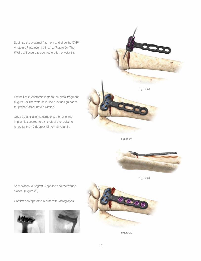
After fixation, autograft is applied and the wound
closed. (Figure 29)
Confirm postoperative results with radiographs.
Figure 29
12 13

Installation of Multi Directional Threaded Peg
Ensure that the fixed-angle pegs have been
installed prior to installing the MDTP.
Remove the F.A.S.T. Guide™ using the peg driver.
Place the 2.0 mm end of the Soft Tissue Guide
(STG) into the radial styloid and/or the most ulnar
hole in the proximal row of the DVR Anatomic plate.
Note: The MDTPs are not recommended for the
distal row.
Place the 2.0 mm drill bit through the STG until
it comes in contact with the bone. Determine the
trajectory of the drill bit by varying the angle of
the STG and drill (Figure 30). The MDTP’s can be
successfully installed within a cone of 20 degrees
off of the fixed angle trajectory.
Assemble the Multi Direct 2.0 mm insert into the
modular handle, verifying that it is firmly attached.
(Figure 31)
Figure 30
Figure 31
Figure 32
Measure the depth of the hole using the flat side of
the F.A.S.T. Bone Depth Gauge (FBDG). (Figure 32)
14 15

Figure 33
Figure 34
Load the appropriately sized MDTP into the driver.
The peg should grip the driver. (Figure 33)
Install the MDTP into the pre-drilled hole. Be careful
to keep the driver fully engaged with the peg. Install
the peg firmly until increased torque yields in no
further rotation. (Figure 34)
Note: For best results, use a new Multi Direct insert
for each surgery. If necessary, after installation the
MDTP can be removed and reinstalled to further
improve positioning.
14 15

Ordering Information
Smooth Peg, LockingProvides subchondral support
10 mm – 30 mm lengths (2 mm steps)
Threaded Peg, LockingDistal threads to capture and lag fragments
10 mm – 30 mm lengths (2 mm steps)
Multi Directional Threaded PegProvides interoperative freedom to vary the trajectory of a fixed angle locking trajectory within a cone of 20 degrees.
10 mm – 30 mm lengths (2 mm steps)
Screws, Non-Locking Fully threaded to anchor fragments for added fixation
10 mm – 30 mm lengths (2 mm steps)
Cortical ScrewsProvide bicortical fixation for proximal fragments
10,12,13,14,15,16, 18 and 20 mm
Pegs and Screws
DVR® Anatomic Plates
Narrow Short: 22.0 mm x 57.0 mmDVRANS LDVRANS R
Wide Standard:31.5 mm x 62.7 mmDVRAW LDVRAW R
Standard Short: 24.4 mm x 51.0 mmDVRAS LDVRAS R
Standard: 24.4 mm x 56.6 mmDVRA LDVRA R
Standard Extended: 24.4 mm x 89.0 mmDVRAX LDVRAX R
Standard Extra Extended:24.4 mm x 175.0 mmDVRAXX LDVRAXX R 16 17

DVR® Anatomic Plate Modular Tray
New fully modular tray system addresses multiple applicationswith the use of a single tray
Reduced OR Instruments•Improved Workflow•
16 17

18 19

18 19

20

DVR® Anatomic PlateEPI date: 1/21/08
ImportantThis Essential Product Information sheet does not include all of the information necessary for selection and use of a device. Please see full labelling for all necessary information.
Indications (DVR® Anatomic and DNP® Anatomic Systems)The Distal Radius Fracture Repair System is intended for the fixation of fractures and osteotomies involving the distal radius.
Indications (Fragment Plate System)The Fragment Plate System is intended for essentially non-load bearing stabilization and fixation of small bone fragments in fresh fractures, revision procedures, joint fusion and reconstruction of small bones of the hand, foot, wrist, ankle, humerus, scapula, finger, toe, pelvis and craniomaxillofacial skeleton.
ContraindicationsIf any of the following are suspected, tests are to be performed prior to implantation. Active or latent infection. Sepsis. Insufficient quantity or quality of bone and/or soft tissue. Material sensitivity. Patients who are unwilling or incapable of following post operative care instructions.
Warning and PrecautionsAlthough the surgeon is the learned intermediary between the company and the patient, the important information conveyed in this document should be conveyed to the patient. The patient must be cautioned about the use, limitations and possible adverse effects of these implants. The patient must be warned that failure to follow postoperative care instructions may cause the implant or treatment to fail.
An implant must never be reused. Previous stresses may have created imperfections that can potentially lead to device failure. Protect implant appliances against scratching or nicking. Such stress concentration can lead to failure.
Orthopaedic instrumentation does not have an indefinite functional life. All re-usable instruments are subjected to repeated stresses related to bone contact, impaction, routine cleaning and sterilization processes. Instruments should be carefully inspected before each use to ensure that they are fully functional. Scratches or dents can result in breakage. Dullness of cutting edges can result in poor functionality. Damaged instruments should be replaced to prevent potential patient injury such as metal fragments into the surgical site. Care should be taken to remove any debris, tissue or bone fragments that may collect on the instrument. Most instrument systems include inserts/trays and a container(s). Many instruments are intended for use with a specific implant system. It is essential that the surgeon and operating theatre staff are fully familiar with the appropriate surgical technique for the instruments and associated implant, if any.
Do NOT open the volar wrist capsule. Doing so may cause devascularisation of the fracture fragments and destabilisation of the •volar wrist ligaments.If necessary, contour the DVR• ® Anatomic plate in small increments. Excessive contouring may weaken or fracture the plate.Exercise care when bending the fragment plates to avoid weakening or fracture of the plates.•Ensure removal of all F.A.S.T. Guide™ inserts after use.•Do NOT use fully threaded pegs (FP) with the DVR• ® Anatomic and DNP® Anatomic plates. The fully threaded pegs (FP) are designed for use with the fragment plates. Do NOT use peg/screw lengths that will excessively protrude through the far cortex. Protrusion through the far cortex may result in •soft tissue irritation. SP series screws are NOT intended to provide subchondral support and use should be limited to capture of remote bone •fragments where partially or fully threaded pegs cannot be used.Do NOT permanently implant K-wires through the holes of the plate as they may back out and cause tissue damage. Use of the •K-wires allows you to provisionally secure the plates to the anatomy.Do NOT use the MDTPs in the distal row of the DVR• ® Anatomic Plate. The MDTPs are intended to be used only with the DVR® Anatomic plates. Ensure the MDTPs are installed after insertion of the fixed angle pegs.
Adverse EffectsThe following are possible adverse effects of these implants: potential for these devices failing as a result of loose fixation and/or loosening, stress, excessive activity, load bearing particularly when the implants experience increased loads due to a delayed union, nonunion, or incomplete healing.
Note: It is NOT required to remove F.A.S.T. Guide™ inserts to sterilize the plate.
20

DePuy Orthopaedics, Inc.700 Orthopaedic Drive Warsaw, IN 46581-0988USATel: +1 (800) 366 8143Fax: +1 (574) 371 4865
Printed in USA. ©2008 DePuy Orthopaedics, Inc. All rights reserved.
0M0000 xxxx-xx-xxx
0086
DePuy International LtdSt Anthony’s RoadLeeds, LS11 8DTEnglandTel: +44 (113) 387 7800Fax: +44 (113) 387 7890
DNP® Anatomic Plate and DVR® Anatomic Plate are registered trademarks and F.A.S.T. Guide™ is a trademark of DePuy Orthopaedics, Inc.