Embed Size (px)
Citation preview
CLINICAL REPORTSPINE
Transmedullary Venous Anastomoses: Anatomy andAngiographic Visualization Using Flat Panel Catheter
AngiotomographyL. Gregg and P. Gailloud
ABSTRACT
SUMMARY: Flat panel catheter angiotomography, a recently developed angiographic technique, offers a spinal equivalent to the venousphase obtained during cerebral angiography. This report of 8 clinical cases discusses the flat panel catheter angiotomography appearanceof a type of spinal venous structure until now principally known through the analysis of postmortem material, transmedullary venousanastomosis. The illustrated configurations include centrodorsolateral, median anteroposterior, median anteroposterior with duplicatedorigin, and combined centrodorsolateral/median anteroposterior transmedullary venous anastomoses, while a pathologic example doc-uments the potential role of transmedullary venous anastomoses as collateral venous pathways. Two of the reported configurations havenot been previously documented. Transmedullary venous anastomoses are normal venous structures that need to be differentiated fromspinal cord anomalies, such as intramedullary vascular malformations.
ABBREVIATIONS: AMSV � anteromedian spinal vein; FPCA � flat panel catheter angiotomography; PLSV � posterolateral spinal vein; PMSV � posteromedianspinal vein; TMVA � transmedullary venous anastomosis
The clinical evaluation of the spinal venous system is techni-
cally challenging, even with spinal DSA, the criterion standard
imaging technique for spinal vasculature. This suboptimal visu-
alization correlates with a poor understanding of spinal venous
system pathology. Flat panel catheter angiotomography (FPCA),
a novel angiographic technique that offers a spinal equivalent to
the cerebral venous phase,1-3 has shown great promise for the
evaluation of the normal and abnormal spinal venous system.3-5
This retrospective review of 8 clinical cases describes the mor-
phology and angiographic appearance of several types of transmed-
ullary venous anastomoses (TMVAs), including some previously un-
documented configurations observed during routine spinal DSA.
TMVAs, rarely observed in living subjects,6-8 were until now essen-
tially known through the study of postmortem material.
CASE SERIESAcquisition ProtocolsThoracic and lumbar protocols involved 20-second nonsub-
tracted rotational angiograms (Artis zee; Siemens, Erlangen, Ger-
many) obtained during the selective injection of arteries provid-
ing major radiculomedullary branches. The contrast mixture
(25% contrast agent, 75% heparinized saline) was injected at a
rate of 1 mL/s for 30 seconds, covering the 20-second angiography
and a 10-second preacquisition delay (total volume of 30 mL,
including 7.5 mL of iodinated agent). The patients were not re-
quired to breath-hold during acquisitions. The volume and rate of
injection were modified for vertebral artery and costocervical
trunk studies (50 mL at 2 mL/s, including 12.5 mL of iodinated
agent). Areas of specific interest were reconstructed using MIP
rendering by the senior author in various planes using high-reso-
lution algorithms (voxel sizes, between 0.2 and 0.04 mm).3
Perimedullary Anastomosis
Case 1. A superficial anastomosis between the anteromedian spinal
vein (AMSV) and the left posterolateral spinal vein (PLSV) was doc-
umented at T12 in a 36-year-old woman with progressive myelopa-
thy (Fig 1).
Centrodorsolateral Anastomosis
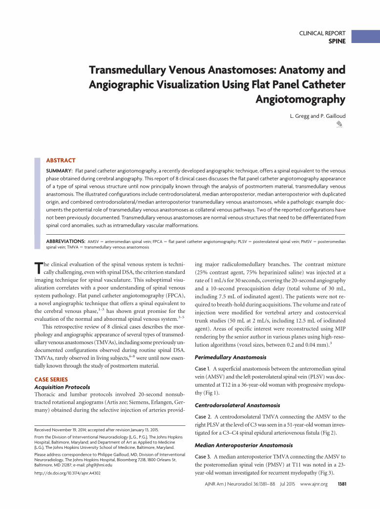
Case 2. A centrodorsolateral TMVA connecting the AMSV to the
right PLSV at the level of C3 was seen in a 51-year-old woman inves-
tigated for a C3–C4 spinal epidural arteriovenous fistula (Fig 2).
Median Anteroposterior Anastomosis
Case 3. A median anteroposterior TMVA connecting the AMSV to
the posteromedian spinal vein (PMSV) at T11 was noted in a 23-
year-old woman investigated for recurrent myelopathy (Fig 3).
Received November 19, 2014; accepted after revision January 13, 2015.
From the Division of Interventional Neuroradiology (L.G., P.G.), The Johns HopkinsHospital, Baltimore, Maryland; and Department of Art as Applied to Medicine(L.G.), The Johns Hopkins University School of Medicine, Baltimore, Maryland.
Please address correspondence to Philippe Gailloud, MD, Division of InterventionalNeuroradiology, The Johns Hopkins Hospital, Bloomberg 7218, 1800 Orleans St,Baltimore, MD 21287; e-mail: [email protected]
http://dx.doi.org/10.3174/ajnr.A4302
AJNR Am J Neuroradiol 36:1381– 88 Jul 2015 www.ajnr.org 1381
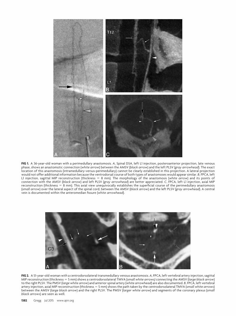
FIG 1. A 36-year-old woman with a perimedullary anastomosis. A, Spinal DSA, left L1 injection, posteroanterior projection, late venousphase, shows an anastomotic connection (white arrow) between the AMSV (black arrow) and the left PLSV (gray arrowhead). The exactlocation of this anastomosis (intramedullary-versus-perimedullary) cannot be clearly established in this projection. A lateral projectionwould not offer additional information because the ventrodorsal course of both types of anastomoses would appear similar. B, FPCA, leftL1 injection, sagittal MIP reconstruction (thickness � 8 mm). The morphology of the anastomosis (white arrow) and its points ofconnection with the AMSV (black arrow) and left PLSV (gray arrowhead) are better appreciated. C, FPCA, left L1 injection, axial MIPreconstruction (thickness � 8 mm). This axial view unequivocally establishes the superficial course of the perimedullary anastomosis(small arrow) over the lateral aspect of the spinal cord, between the AMSV (black arrow) and the left PLSV (gray arrowhead). A centralvein is documented within the anteromedian fissure (white arrowhead).
FIG 2. A 51-year-old woman with a centrodorsolateral transmedullary venous anastomosis. A, FPCA, left vertebral artery injection, sagittalMIP reconstruction (thickness � 5 mm) shows a centrodorsolateral TMVA (small white arrows) connecting the AMSV (large black arrow)to the right PLSV. The PMSV (large white arrow) and anterior spinal artery (white arrowhead) are also documented. B, FPCA, left vertebralartery injection, axial MIP reconstruction (thickness � 5 mm) shows the path taken by the centrodorsolateral TMVA (small white arrows)between the AMSV (large black arrow) and the right PLSV. The PMSV (larger white arrow) and segments of the coronary plexus (smallblack arrows) are seen as well.
1382 Gregg Jul 2015 www.ajnr.org
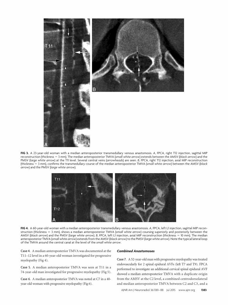
Case 4. A median anteroposterior TMVA was documented at the
T11–12 level in a 60-year-old woman investigated for progressive
myelopathy (Fig 4).
Case 5. A median anteroposterior TMVA was seen at T11 in a
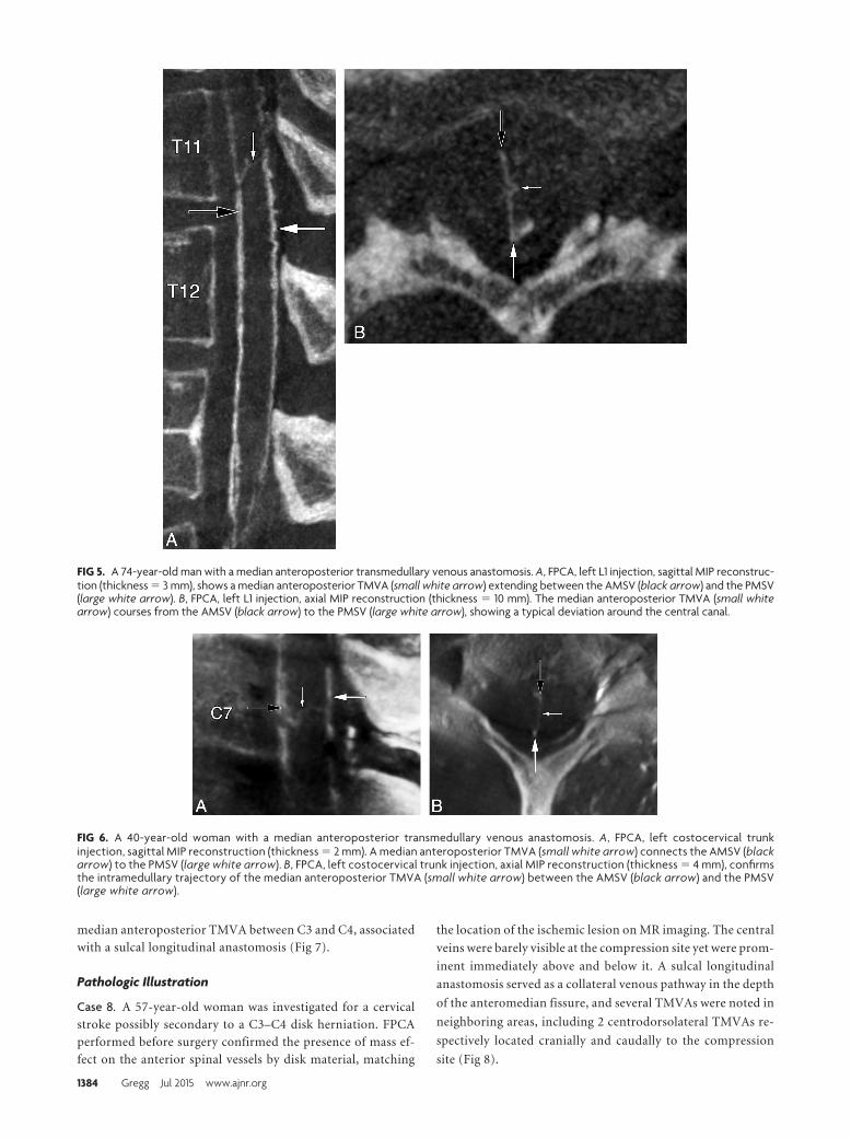
74-year-old man investigated for progressive myelopathy (Fig 5).
Case 6. A median anteroposterior TMVA was noted at C7 in a 40-
year-old woman with progressive myelopathy (Fig 6).
Combined Anastomoses
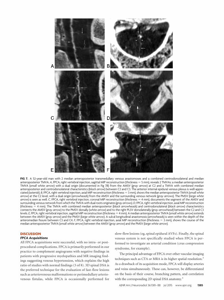
Case 7. A 52-year-old man with progressive myelopathy was treated
endovascularly for 2 spinal epidural AVFs (left T7 and T9). FPCA
performed to investigate an additional cervical spinal epidural AVF
showed a median anteroposterior TMVA with a duplicate origin
from the AMSV at the C2 level, a combined centrodorsolateral
and median anteroposterior TMVA between C2 and C3, and a
FIG 3. A 23-year-old woman with a median anteroposterior transmedullary venous anastomosis. A, FPCA, right T12 injection, sagittal MIPreconstruction (thickness � 3 mm). The median anteroposterior TMVA (small white arrow) extends between the AMSV (black arrow) and thePMSV (large white arrow) at the T11 level. Several central veins (arrowheads) are seen. B, FPCA, right T12 injection, axial MIP reconstruction(thickness � 3 mm), confirms the transmedullary course of the median anteroposterior TMVA (small white arrow) between the AMSV (blackarrow) and the PMSV (large white arrow).
FIG 4. A 60-year-old woman with a median anteroposterior transmedullary venous anastomosis. A, FPCA, left L1 injection, sagittal MIP recon-struction (thickness � 3 mm), shows a median anteroposterior TMVA (small white arrow) coursing superiorly and posteriorly between theAMSV (black arrow) and the PMSV (large white arrow). B, FPCA, left L1 injection, axial MIP reconstruction (thickness � 10 mm). The mediananteroposterior TMVA (small white arrow) extends from the AMSV (black arrow) to the PMSV (large white arrow). Note the typical lateral loopof the TMVA around the central canal at the level of the small white arrow.
AJNR Am J Neuroradiol 36:1381– 88 Jul 2015 www.ajnr.org 1383
median anteroposterior TMVA between C3 and C4, associated
with a sulcal longitudinal anastomosis (Fig 7).
Pathologic Illustration
Case 8. A 57-year-old woman was investigated for a cervical
stroke possibly secondary to a C3–C4 disk herniation. FPCA
performed before surgery confirmed the presence of mass ef-
fect on the anterior spinal vessels by disk material, matching
the location of the ischemic lesion on MR imaging. The central
veins were barely visible at the compression site yet were prom-
inent immediately above and below it. A sulcal longitudinal
anastomosis served as a collateral venous pathway in the depth
of the anteromedian fissure, and several TMVAs were noted in
neighboring areas, including 2 centrodorsolateral TMVAs re-
spectively located cranially and caudally to the compression
site (Fig 8).
FIG 5. A 74-year-old man with a median anteroposterior transmedullary venous anastomosis. A, FPCA, left L1 injection, sagittal MIP reconstruc-tion (thickness � 3 mm), shows a median anteroposterior TMVA (small white arrow) extending between the AMSV (black arrow) and the PMSV(large white arrow). B, FPCA, left L1 injection, axial MIP reconstruction (thickness � 10 mm). The median anteroposterior TMVA (small whitearrow) courses from the AMSV (black arrow) to the PMSV (large white arrow), showing a typical deviation around the central canal.
FIG 6. A 40-year-old woman with a median anteroposterior transmedullary venous anastomosis. A, FPCA, left costocervical trunkinjection, sagittal MIP reconstruction (thickness � 2 mm). A median anteroposterior TMVA (small white arrow) connects the AMSV (blackarrow) to the PMSV (large white arrow). B, FPCA, left costocervical trunk injection, axial MIP reconstruction (thickness � 4 mm), confirmsthe intramedullary trajectory of the median anteroposterior TMVA (small white arrow) between the AMSV (black arrow) and the PMSV(large white arrow).
1384 Gregg Jul 2015 www.ajnr.org
DISCUSSIONFPCA AcquisitionsAll FPCA acquisitions were successful, with no intra- or post-
procedural complications. FPCA is primarily performed in our
practice to complement angiograms with negative findings in
patients with progressive myelopathies and MR imaging find-
ings suggesting venous hypertension, which explains the high
ratio of studies with normal findings (5 of 8). 3D spinal DSA is
the preferred technique for the evaluation of fast-flow lesions
such as arteriovenous malformations or perimedullary arterio-
venous fistulas, while FPCA is occasionally performed for
slow-flow lesions (eg, spinal epidural AVFs). Finally, the spinal
venous system is not specifically studied when FPCA is per-
formed to investigate an arterial condition (crus compression
syndrome, for example).
The principal advantage of FPCA over other vascular imaging
techniques such as CTA or MRA is its higher spatial resolution.3
As a drawback of its acquisition mode, FPCA will display arteries
and veins simultaneously. These can, however, be differentiated
on the basis of their course, branching pattern, and correlation
with the corresponding 2D spinal DSA anatomy.3
FIG 7. A 52-year-old man with 2 median anteroposterior transmedullary venous anastomoses and a combined centrodorsolateral and mediananteroposterior TMVA. A, FPCA, right vertebral injection, sagittal MIP reconstruction (thickness � 5 mm), reveals 2 TMVAs: a median anteroposteriorTMVA (small white arrow) with a dual origin (documented in Fig 7B) from the AMSV (gray arrow) at C2 and a TMVA with combined mediananteroposterior and centrodorsolateral characteristics (black arrow) between C2 and C3. The anterior internal epidural venous plexus is well-appre-ciated (asterisk). B, FPCA, right vertebral injection, axial MIP reconstruction (thickness � 3 mm), shows the median anteroposterior TMVA (small whitearrow) at the C2 level, with a dual origin (arrowheads) from the AMSV and the surrounding venous network (gray arrows). The PMSV (large whitearrow) is seen as well. C, FPCA, right vertebral injection, coronal MIP reconstruction (thickness � 4 mm), documents the segment of the AMSV andsurrounding venous network from which the TMVA with dual roots originates (gray arrows). D, FPCA, right vertebral injection, axial MIP reconstruction(thickness � 4 mm). The TMVA with combined median anteroposterior (black arrowheads) and centrodorsolateral (black arrow) characteristicsconnects the AMSV (gray arrow) to the PMSV dorsally (white arrow) and to the right PLSV dorsolaterally (gray arrowhead) between the C2 and C3levels. E, FPCA, right vertebral injection, sagittal MIP reconstruction (thickness � 4 mm). A median anteroposterior TMVA (small white arrow) extendsbetween the AMSV (gray arrow) and the PMSV (large white arrow). A sulcal longitudinal anastomosis (arrowheads) is seen within the depth of theanteromedian fissure between C3 and C4. F, FPCA, right vertebral injection, axial MIP reconstruction (thickness � 3 mm), shows the course of themedian anteroposterior TMVA (small white arrow) between the AMSV (gray arrow) and the PMSV (large white arrow).
AJNR Am J Neuroradiol 36:1381– 88 Jul 2015 www.ajnr.org 1385
Anatomy of the Perimedullary and IntramedullaryVenous SystemsThe perimedullary venous system includes the AMSV and PMSV,
which are 2 anastomotic chains respectively coursing over the
anteromedian and posteromedian fissures. The smaller paired
PLSVs lie along the dorsal nerve rootlets (Fig 9A). 9,10 The prin-
cipal longitudinal venous axes are interconnected by the coronary
plexus of the pia mater.11 The coronary plexus generally includes
a few larger perimedullary anastomoses that can be visualized
during spinal DSA, if the venous phase is of sufficient quality.
However, perimedullary anastomoses are not clearly distin-
guished from TMVAs without the multiplanar assistance of FPCA
(Fig 1).3
The intramedullary venous network is divided into central and
peripheral compartments (Fig 9A). The central veins drain the
anterior and median portions of the spinal parenchyma12 and
terminate into the AMSV. Neighboring central veins can establish
longitudinal anastomotic chains, both within the central gray
matter (paracentral longitudinal anastomosis) and the anterome-
dian fissure (sulcal longitudinal anastomosis).12 Paracentral lon-
gitudinal anastomoses can participate in aberrant intramedullary
drainage patterns similar to the developmental venous anomalies
seen in the brain or brainstem.4 When prominent, sulcal or para-
central longitudinal anastomoses can be visualized with FPCA
(Fig 7E).
The peripheral veins course radially to end in the coronary
plexus. Those located within the anterior and posterior radicular
fasciculi are generally more developed.13 The septal veins drain
into the PMSV. All intrinsic veins drain centrifugally into the
perimedullary venous system.14,15
Transmedullary Venous AnastomosesTwo types of TMVAs are classically recognized. The centrodorso-
lateral type was described by Kadyi11 in 1889 (Fig 10):
A large anastomotic connection is established between one of the
central veins and one from the posterior surface of the spinal cord.
The small trunk designated by “v” does not course within the
median septum, but leftward to reach the surface of the spinal
cord in the vicinity of the line of emergence of the left posterior
nerve rootlets…. The venous anastomosis “a” forms a loop, both
legs of which run parallel to the central canal: one goes down, the
other one goes up and follows a S-shaped curve before reaching
the trunk of the corresponding central vein “c” (p 146, P.G.
translation).
In 1939, Herren and Alexander14 further defined the centrodor-
solateral anastomosis as being formed by a central vein connect-
ing to a paracentral vein, itself continuing as a long oblique ve-
nous channel that terminates in the ipsilateral PLSV (Fig 9B).
FIG 8. A 57-year-old woman with a sulcal longitudinal anastomosis and 2 centrodorsolateral transmedullary venous anastomoses. A, FPCA, leftvertebral injection, sagittal MIP reconstruction (thickness � 5 mm), shows mass effect on the anterior aspect of the spinal cord by protrudeddisk material at C3–C4 (asterisk), with a dearth of central veins at the corresponding level. The central veins above and below the lesion areprominent. A sulcal longitudinal anastomosis (white arrowheads) appears to serve as a collateral venous pathway in the depth of the antero-median fissure. Two centrodorsolateral TMVAs are noted, respectively located cranially (white arrow) and caudally (black arrow) to thecompressed area. B, FPCA, left vertebral injection, axial MIP reconstruction (thickness � 3 mm), shows the C2–C3 centrodorsolateral TMVA(small white arrows) connecting the AMSV (large black arrow) to the left PLSV (gray arrowhead). The PMSV (large white arrow) is seen as well.C, FPCA, left vertebral injection, axial MIP reconstruction (thickness � 2 mm), documents a second centrodorsolateral TMVA (small whitearrows) at C4 –C5, extending between the AMSV (large black arrow) and left PLSV (gray arrowhead), which continues its course medially toconnect with the PMSV (large white arrow).
1386 Gregg Jul 2015 www.ajnr.org
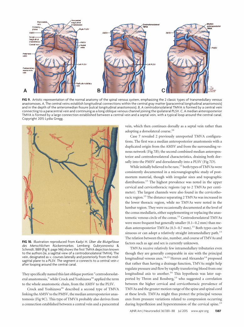
They specifically named this last oblique portion “centrodorsolat-
eral anastomosis,” while Crock and Yoshizawa16 applied the term
to the whole anastomotic chain, from the AMSV to the PLSV.
Crock and Yoshizawa16 described a second type of TMVA
linking the AMSV to the PMSV, the median anteroposterior anas-
tomosis (Fig 9C). This type of TMVA probably also derives from
a connection established between a central vein and a paracentral
vein, which then continues dorsally as a septal vein rather than
adopting a dorsolateral course.16
Case 7 revealed 2 previously unreported TMVA configura-
tions. The first was a median anteroposterior anastomosis with a
duplicated origin from the AMSV and from the surrounding ve-
nous network (Fig 7B); the second combined median anteropos-
terior and centrodorsolateral characteristics, draining both dor-
sally into the PMSV and dorsolaterally into a PLSV (Fig 7D).
While initially believed to be rare,12 both types of TMVAs were
consistently documented in a microangiographic study of post-
mortem material, though with irregular sizes and topographic
distributions.15 The highest prevalence was noted in the upper
cervical and cervicothoracic regions (up to 2 TMVAs per centi-
meter). The largest channels were also found in the cervicotho-
racic region.15 The distance separating 2 TMVAs was increased in
the lower thoracic region, while no TMVAs were noted in the
lumbar region. They were occasionally documented at the level of
the conus medullaris, either supplementing or replacing the anas-
tomotic venous circle of the conus.15 Centrodorsolateral TMVAs
were more frequent but generally smaller (0.1– 0.2 mm) than me-
dian anteroposterior TMVAs (0.3– 0.7 mm).15 Both types can be
sinuous or can adopt a relatively straight intramedullary path.15
The relation between the size, number, and course of TMVAs and
factors such as age and sex is currently unknown.
TMVAs receive relatively few intramedullary tributaries even
though they are generally comparable in size with the principal
longitudinal venous axes.14,15 Herren and Alexander14 proposed
that rather than having a drainage function, TMVAs might help
regulate pressure and flow by rapidly transferring blood from one
longitudinal axis to another.14 This hypothesis was later sup-
ported by Thron and Rossberg,15 who suggested a correlation
between the higher cervical and cervicothoracic prevalence of
TMVAs and the greater motion range of the spine and spinal cord
at these levels. TMVAs might thus protect the principal venous
axes from pressure variations related to compression occurring
during hyperflexion and hyperextension of the cervical spine.15
FIG 9. Artistic representation of the normal anatomy of the spinal venous system, emphasizing the 2 classic types of transmedullary venousanastomoses. A, The central veins establish longitudinal connections within the central gray matter (paracentral longitudinal anastomosis)and in the depth of the anteromedian fissure (sulcal longitudinal anastomosis). B, A centrodorsolateral TMVA is formed by a central veinconnecting to a paracentral vein and continuing as a long oblique venous channel joining the ipsilateral PLSV. C, A median anteroposteriorTMVA is formed by a large connection established between a central vein and a septal vein, with a typical loop around the central canal.Copyright 2015 Lydia Gregg.
FIG 10. Illustration reproduced from Kadyi H. Uber die Blutgefassedes Menschlichen Ruckenmarkes. Lemberg: Gubryonowisz &Schmidt; 1889 (Fig 9, page 146) shows the first TMVA depiction knownto the authors (ie, a sagittal view of a centrodorsolateral TMVA). Thevein, designated as v, courses laterally and posteriorly from the mid-sagittal plane to a PLSV. The segment a connects to a central vein cafter looping around the central canal.
AJNR Am J Neuroradiol 36:1381– 88 Jul 2015 www.ajnr.org 1387
Our last example (case 8) suggests that under abnormal circum-
stances leading to impaired venous flow, TMVAs may indeed act
as alternate drainage pathways limiting the risk of venous en-
gorgement and ischemia (Fig 8). In this patient, a sulcal longitu-
dinal anastomosis also appeared to play the role of a collateral
pathway in the area compressed by protruding disk material.
Recognizing TMVAs as normal structures carries both diag-
nostic and therapeutic implications. For example, TMVAs were
recently used as an access route for successful obliteration of a
perimedullary arteriovenous fistula.8 Median anteroposterior
TMVAs have been documented by contrast-enhanced MRA and
by DSA,6,7,17 while centrodorsolateral TMVAs have, to our
knowledge, not been imaged clinically until now, probably be-
cause of their smaller size.15 New imaging methods such as spinal
SWI also require a sound understanding of the spinal venous sys-
tem anatomy and its variants, for example, to differentiate
TMVAs from small intraparenchymal hemorrhages.18
In summary, the introduction of novel imaging techniques,
such as spinal FPCA or SWI, can strengthen our still deficient
understanding of medullary venous pathology. This improved
imaging ability creates the need for a more intricate knowledge of
the anatomy of the spinal venous system. This article reports sev-
eral types of TMVAs documented by FPCA. Some of these vessels
were previously known, in general from postmortem investiga-
tions, while others had not yet been described. Appreciating the
existence of TMVAs is clinically important because these channels
may be confused with intramedullary hemorrhages or vascular
malformations on noninvasive imaging.
Disclosures: Philippe Gailloud—UNRELATED: Consultancy: Codman Neurovascular;Grants/Grants Pending: Siemens Medical*; Stock/Stock Options: Artventive Medi-cal; Other: Consultant for Penumbra. *Money paid to the institution.
REFERENCES1. Akpek S, Brunner T, Benndorf G, et al. Three-dimensional imaging
and cone beam volume CT in C-arm angiography with flat paneldetector. Diagn Interv Radiol 2005;11:10 –13
2. Zellerhoff M, Scholz B, Ruehrnschopf EP, et al. Low contrast 3D
reconstruction from C-arm data. SPIE Proceedings 2005;5745:646 –55
3. Chen J, Ethiati T, Gailloud P. Flat panel catheter angiotomographyof the spinal venous system: an enhanced venous phase for spinaldigital subtraction angiography. AJNR Am J Neuroradiol 2012;33:1875– 81
4. Pearl MS, Chen JX, Gregg L, et al. Angiographic detection and char-acterization of “cryptic venous anomalies” associated with spinalcord cavernous malformations using flat-panel catheter angioto-mography. Neurosurgery 2012;71:125–32
5. Aadland TD, Thielen KR, Kaufmann TJ, et al. 3D C-arm conebeamCT angiography as an adjunct in the precise anatomic characteriza-tion of spinal dural arteriovenous fistulas. AJNR Am J Neuroradiol2010;31:476 – 80
6. Thron AK. Vascular anatomy of the spine and spinal cord. In: HurstRW, Rosenwasser RH, eds. Neurointerventional Management: Diag-nosis and Treatment. Boca Raton, FL: CRC Press; 2012:40 –58
7. Krings T. Vascular malformations of the spine and spinal cord*:anatomy, classification, treatment. Clin Neuroradiol 2010;20:5–24
8. Giese A, Winkler PA, Schichor C, et al. A transmedullary approach toocclusion of a ventral perimedullary arteriovenous fistula of thethoracic spinal cord. Neurosurgery 2010;66:611–15
9. Suh T, Alexander L. Vascular system of the human spinal cord. ArchNeurol Psychiatry 1939;41:659 –77
10. Zhang ZA, Nonaka H, Hatori T. The microvasculature of the spinalcord in the human adult. Neuropathology 1997;17:32– 42
11. Kadyi H. Uber die Blutgefasse des Menschlichen Ruckenmarkes.Lemberg: Gubryonowisz & Schmidt; 1889
12. Gillilan LA. Veins of the spinal cord: anatomic details—suggestedclinical applications. Neurology 1970;20:860 – 68
13. Lazorthes G, Gouaze A, Djindjian R. Vascularisation et circulation dela moelle epiniere: anatomie, physiologie, pathologie, angiographie.Paris: Masson & Cie; 1973
14. Herren RY, Alexander L. Sulcal and intrinsic blood vessels of thehuman spinal cord. Arch Neurol Psychiatry 1939;41:678 – 87
15. Thron AK, Rossberg C, Mironov A. Vascular Anatomy of the SpinalCord: Neuroradiological Investigations and Clinical Syndromes. NewYork: Springer-Verlag Wien; 1988
16. Crock HV, Yoshizawa H. The Blood Supply of the Vertebral Columnand Spinal Cord in Man. New York: Springer-Verlag; 1977
17. Thron A, Mull M. Blood vessels of the spinal cord: anatomicaland MR-imaging correlation. Rivista di Neuroradiologia 2004;17:277– 81
18. Ishizaka K, Kudo K, Fujima N, et al. Detection of normal spinal veinsby using susceptibility-weighted imaging. J Magn Reson Imaging2010;31:32–38
1388 Gregg Jul 2015 www.ajnr.org