Embed Size (px)
Citation preview

EASTERN INSTRUMENTS
Precision Material Handling Equipment
TYPE II SOLIDS MASS FLOW METERS

Type II Solids Flow Meters2
About Eastern InstrumentsEastern Instruments, a Certified Women’s Business Enterprise, is an engineered solutions company located adjacent to the North Carolina International State Port in Wilmington, North Carolina. Since 1984, we have been engaged in the design and manufacture of devices that measure and control the flow of industrial bulk solids. These devices have been integrated into a variety of systems for regulating operations and improving efficiency across nearly every industrial sector. Every device within Eastern Instruments’ solids flow measurement product line provides a high degree of accuracy, easy installation, a minimal footprint and extremely simple and intuitive operation and maintenance for both continuous and batch operations.
The following catalog is for our Type II Mass Flow Meters. For more information on our other products, please see all of our available catalogs. We offer an entire line of feeders, fillers and other specialty solids flow devices, so if you are in need of equipment other than a mass flow meter, Eastern Instruments can help.
Contact us today.
Mildred R. Brandt President and CEO
Eastern InstrumentsMaterial Handling Solutions
416 Landmark DriveWilmington, NC 28412
Phone: 910.392.2490Fax: 910.392.2123
www.easterninstruments.com
FOR MORE INFORMATIONCALL (910) 392-2490
Options
06
Electronics
18
Type II Flow Meters
16
04Applications

Type II Solids Flow Meters 3
EIThe Principle of Centripetal Force and the Science Behind our Solids Flow Meters
Measures Centripetal Force, not the Impact
of Particles
Why are the solids flow measurement and control devices from Eastern Instruments so accurate? The secret lies in their zero-friction patented design, which is based on the principle of centripetal force.
Centripetal force is the inward force required to keep an object moving in a circular path. It can be shown that an object moving in a circular path has acceleration towards the center of the circle along a radius.
This radial acceleration, called the centripetal acceleration, is such that if an object has a linear or tangential velocity when moving in a circular path of radius (R), the centripetal acceleration is v2/R. If the object undergoing the centripetal acceleration has a mass (M), then by Newton’s second law of motion, the centripetal force (Fc) is in the direction of acceleration. This is expressed by the formula:
From Newton’s first law of motion, it follows that the natural motion of an object is one with constant speed in a straight line and that a force is necessary if the object is to depart from this type of motion. The force present when an object moves in a curve is called centripetal force.
The CentriFlow® Meter and all of the products in our Solids Flow Measurement Product Line actually measure the centripetal force exerted on the curved surface, in this case, the Measurement Pan, as particles travel over it. The meter does not measure the impact of particles because they never impact the Measurement Pan. Rather, they slide across the Pan for a longer duration, thus resulting in a significantly more accurate signal.
Based on the patented design of these unique devices, they are able to identify and cancel the friction component and, when combined with a velocity that is constant and a radius that is unchanging, the flow equals mass. In this manner, the flow signal from our devices is an actual mass flow, which is linear and accurate, and is not affected by density or slight particle size variations. This is Zero Friction Flow Measurement.

Type II Solids Flow Meters
CENTRIFLOW®: ACCURATE MEASUREMENT FOR MANY APPLICATIONS
Potato Chips
Industrial Powders
Crushed Glass
Sand/SilicaSnack Mix
Fish Feed
Gravel
Coffee Beans
Corn Meal RiceFeed Pellets
Plastic Pellets
Tortilla Chips
4
Petrochemical• Rubber Products• Oil Extraction• Petrochemicals• Plastics/Additives
Construction• Drywall/Plywood• Concrete Products• Engineered Materials• Recycled Materials• Roofing Products• Asphalt Products
Industrial Chemicals• Industrial Powders• Consumer Goods• Glass Ceramics• Mining
Food• Baked Goods• Beans and Grains• Dried Foods• Snack Foods/Cereals• Beverages• Tobacco Products
Recycling• Recycled Plastics• Renewable Energy• Construction Materials• Asphalt Production
Agricultural• Beans/Grains• Nuts• Fertilizers/Additives• Corn Products
Pet Products• Feed Pellets• Additives• Kibble• Litter/Bedding
Energy Production• Bio-Energy Feedstocks• Ethanol Production• Renewable Energy• Coal-Fired Energy
The CentriFlow Meter:Exceeding Expectation
in Every Industry. Contact Us Today.
Applications

Type II Solids Flow Meters
EIEASTERN INSTRUMENTS
VISIT EASTERN INSTRUMENTS ON FOR PRODUCT VIDEOS
Chopped HayPET Flake
Dried CornDried Cranberries Raw SugarPet Kibble Flour
Plastic Bags
Gummy Candy Pretzels Wood ShavingsMalted Barley
Wood Chips
Why choose the CentriFlow®?Accuracy
Unlike existing technologies that calculate mass flow by making assumptions based on weight, speed, belt tension, or volume, the CentriFlow® Meter actually measures flowable solids in a process. This unique measurement ability allows the CentriFlow® Meter to have a typical ±0.25% accuracy full scale on virtually all flowable solids, significantly improving the industry standard.
Turndown Ratio
The CentriFlow® Meter can maintain its accuracy over a large turndown ratio and an additional Multiple Calibration option is available for extreme turndowns. Because the meter’s unique design enables it to identify and cancel the friction component, the resulting mass flow signal = mass rate. This linear relationship allows the meter to measure at a typical accuracy of ±0.25% full scale and is unaffected by wide variances in rate.
Solid Construction / Low Maintenance
The CentriFlow® Meter’s sturdy high-grade aluminum construction and stainless steel flow paths create a very low maintenance instrument. With no moving parts, it rarely requires recalibration and its solid-construction, low-maintenance design requires very few spare parts.
Plant Efficient Configurations
Designed to fit into nearly any existing process, the CentriFlow® Meter is available in multiple configurations that minimize the need for costly changes to your process. The Type I Configuration is designed to mount at the end of any existing horizontal feed system, while the Type II Configuration is designed for any in-line vertical feed system. Compared to alternatives, the CentriFlow® Meter's compact, space efficient design requires a small footprint.
Flexibility
The CentriFlow® Meter is not affected by changes in product elasticity, density, shape or friction and even fluctuations in flow rate don’t impact its accuracy. The linearity of the zero friction formula underlying the meter’s design allows the CentriFlow® Meter to measure at various densities and turndown ratios, while maintaining near perfect accuracy.
Continuous Measurement for Continuous Improvement
The CentriFlow® Meter’s ability to provide an accurate and real-time, continuous mass flow measurement allows you to optimize your process like never before. The ability to measure gives you the control to manage.
5

Type II Solids Flow Meters6
Type II Meter
The CentriFlow® Type II Meter is a solids mass flow meter designed to measure bulk solids continuously in a process and is specially designed to be installed directly after feed devices that move material in a vertical direction such as rotary valves, screw conveyors, bucket elevators, etc. Perfect for installation in both new construction, or retrofitted into existing processes, the CentriFlow® Type II Meter has a small, vertical footprint as compared to other metering devices on the market. The vertical footprint of the Standard Type II Meter is only 36" in vertical height. With many options available as well as a variety of customizable features, the Type II meter can be optimized to measure nearly any product from highly abrasive industrial materials to flours and powders.
While the Type II Meter can be used to measure both free-flowing materials as well as powdery materials, the enclosure or housing of the Type II Meter lends itself perfectly to applications where measuring powders or other products can create a great deal of dust. In addition, many options are available to enhance the flow of particularly stubborn materials, or to protect against abrasion. Additional options for explosion hazards are also available for all models of the Type II Meter.
The Type II Meter is available in several specialized models (as shown to the right) which range in scope from the Low Flow model CFL to the High Flow, High Density model HDM.
With a variety of customizable features and models to choose from, there is a CentriFlow® Type II Meter designed with your particular process in mind.
CFM Type II: Standard
• Meter with Enclosure• Perfect for Most Flow Rates
and Materials• Fed by Rotary Valve, Screw
Conveyor, Bucket Elevator, etc.• For Granular Products as well
as Powdery Products
BWS Type II: Budget
• Meter with Enclosure• Perfect for Grains, or Pellets• Can be directly coupled to
gravity fed pipe or feed device• Extremely Economical Design
CFL Type II: Low Flow
• Meter with Enclosure• Perfect for Very Low Flow
Rates• Fed by Rotary Valve, Screw
Conveyor, Bucket Elevator, etc.• For Free-Flowing or Powdery
Materials
HDM Type II: Heavy Duty
• Meter with Enclosure• Perfect for Heavy, High-
Density Materials• Fed by Rotary Valve, Screw
Conveyor, Bucket Elevator, etc.• For Free-Flowing or Powdery
Materials
CentriFlow®: Type II Models
CentriFlow® Type II Meter:
Scan the QR Code for a link to the Type II Meter on our
website.

Type II Solids Flow Meters
EIEASTERN INSTRUMENTS
7
CentriFlow: Type II InstallationsThe CentriFlow® Meter is typically installed directly after a feed device in order to ensure a consistent flow of product through your meter. Consistent however, does not mean continuous. Due to its rugged construction and unique design, the Type II Meter is perfect for installation after a variety of feed devices, including those that generate highly pulsating flows or surges of product. Some of the more common feed devices that the Type II Meter is installed after are listed below.
SCREW CONVEYOR: The pulsations of screw conveyors have little effect on the Type II Meter's accuracy. The high sample rate and instantaneous measurement of the meter ensures that surges in product will always be measured accurately.
BUCKET ELEVATOR: Because bucket elevators typically move product in a vertical direction, they are perfect for Type II Meters which require a vertical feed device. Product typically transitions from the bucket before entering into the CentriFlow®.
SLIDE GATE: Slide gates create a very consistent feed of product for the CentriFlow® Type II Meter and allow for very accurate measurement. If you require both flow measurement and control of your product, the CentriFeeder® with ICV combines a CentriFlow® Meter with an Integrated Control Gate for very accurate measurement and control of granular products. See our Feeder catalog for more information.
ROTARY VALVE: As with screw conveyors, flow out of rotary valves is often very pulsating and large rotary valves can cause an even greater likelihood of large pulsations. Even these large pulsations, however, have very little effect on the accuracy of the CentriFlow® Type II Meter. In the unlikely event that an extremely large surge floods the meter with product, the meter's enclosure is designed to allow the product flow to continue through the process without blockage so that production can continue unhindered by the unexpected surge in product.
Product Examples
• Plastic Pellets• Animal Feed• Grains• Coffee Beans• Fertilizer
• Granules• Pellets• Milled Grains• Chips/Chunks
Slide Gate/Orifice Valve
Product Examples
• Plastic Pellets• Animal Feed• Grains• Coffee Beans• Fertilizer
• Powders• Gypsum• Milled Grains• Cement
Rotary ValveProduct Examples
• Plastic Pellets• Animal Feed• Grains• Coffee Beans• Fertilizer
• Powders• Gypsum• Milled Grains• Cement
Screw Conveyor
Product Examples
• Plastic Pellets• Animal Feed• Grains• Coffee Beans• Fertilizer
Bucket Elevator
• Powders• Gypsum• Grains• Cement

Type II Solids Flow Meters8
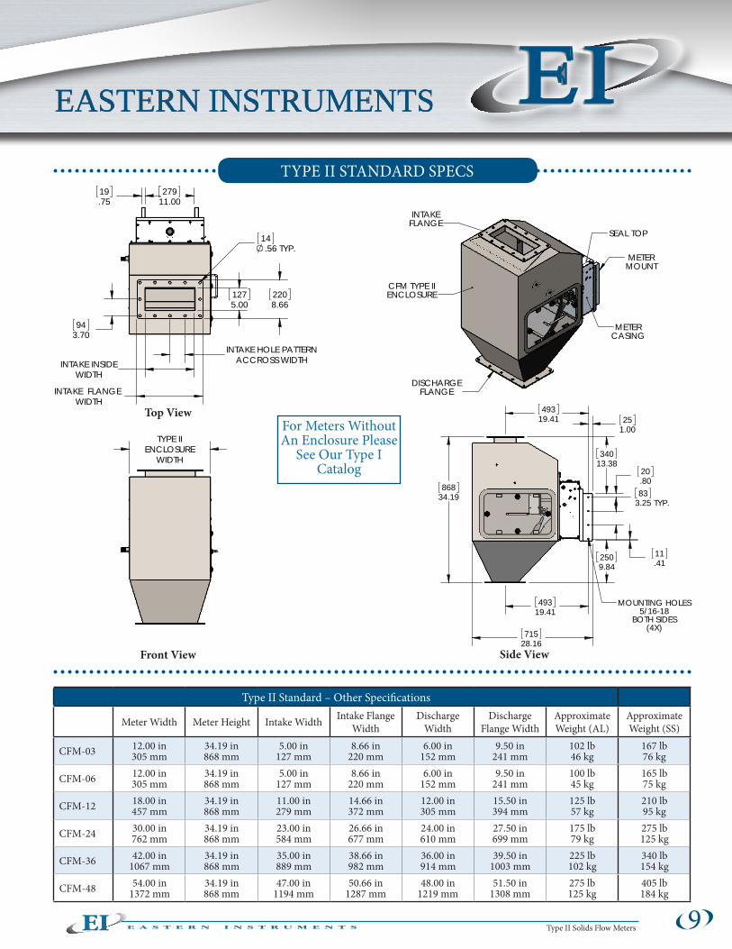
The CentriFlow® Type II Meter is a bulk solids mass flow meter specially designed to be installed directly after feed devices that move material in a vertical direction such as slide gates, rotary air locks, or screw conveyors. The Type II Meter features an enclosure that houses the meter and ensures that the flow path is contained. The housing is flanged on both the intake and discharge chute in order to make installation extremely easy. Although larger than the Type I Meter, the standard Type II enclosure requires less than 36” of vertical space. For tighter fits, custom enclosures are also available. The Type II Meter is great for free-flowing products and powders alike and works especially well for applications where flows pulsate, such as after rotary valves or screw conveyors. The standard Type II Meter can be specially configured to measure nearly any solid material.
CFM Type II: Standard
Material Specification• Standard meter parts (other than product contact
surfaces) are constructed of 6061 aluminum. Stainless Steel also available.
• Standard product contact surfaces (parts within product flow path), as well as Type II enclosure, constructed out of 304 Stainless Steel.
• A selection of customizable liners and coatings is available on all flow surfaces for aiding in product flowability or for improving wear resistance against particularly abrasive materials.
Design Specification • The Tangential can be vertical (for granular
materials), or tipped backward at 10 degrees as is the case with the powder version of the meter.
• The Diverter is set at a 45 degree angle of repose (56 degree for Powder version).
• The standard height for all sizes of the CFM meter is under 36" in height. They are typically installed directly after feed devices, minimizing stackup.
• Custom enclosures are available for shrinking the vertical footprint of the meter or for incorporating special transitions within the enclosure design.
Volumetric Capacity of the CentriFlow® Meter for the Type II STANDARD ft3/min (m3/hr)
Meter SizeGranular Products Powdery Products
Min Max Min Max
CFM-03 0.63 (1.06)
5.00 (8.50)
1.25 (2.12)
3.75 (6.37)
CFM-06 1.69 (2.87)
13.50 (22.94)
3.38 (5.73)
10.13 (17.20)
CFM-12 3.75 (6.37)
30.00 (50.97)
7.50 (12.74)
22.50 (38.23)
CFM-24 7.50 (12.74)
60.00 (101.94)
15.00 (25.49)
45.00 (76.46)
CFM-36 11.25 (19.11)
90.00 (152.91)
22.50 (38.23)
67.50 (114.68)
CFM-48 15.00 (25.49)
120.00 (203.88)
30.00 (50.97)
90.00 (152.91)TYPE II STANDARD METER
Diverter
Tang
entia
l
Measurement Pan
Dusty Materials
Granular Products
Sticky or Clumping
Free Flowing
Type II Solids Flow Meters
EIEASTERN INSTRUMENTS
9
Type II Standard – Other Specifications
Meter Width Meter Height Intake Width Intake Flange Width
Discharge Width
Discharge Flange Width
Approximate Weight (AL)
Approximate Weight (SS)
CFM-03 12.00 in 305 mm
34.19 in 868 mm
5.00 in 127 mm
8.66 in 220 mm
6.00 in 152 mm
9.50 in 241 mm
102 lb 46 kg
167 lb 76 kg
CFM-06 12.00 in 305 mm
34.19 in 868 mm
5.00 in 127 mm
8.66 in 220 mm
6.00 in 152 mm
9.50 in 241 mm
100 lb 45 kg
165 lb 75 kg
CFM-12 18.00 in 457 mm
34.19 in 868 mm
11.00 in 279 mm
14.66 in 372 mm
12.00 in 305 mm
15.50 in 394 mm
125 lb 57 kg
210 lb 95 kg
CFM-24 30.00 in 762 mm
34.19 in 868 mm
23.00 in 584 mm
26.66 in 677 mm
24.00 in 610 mm
27.50 in 699 mm
175 lb 79 kg
275 lb 125 kg
CFM-36 42.00 in 1067 mm
34.19 in 868 mm
35.00 in 889 mm
38.66 in 982 mm
36.00 in 914 mm
39.50 in 1003 mm
225 lb 102 kg
340 lb 154 kg
CFM-48 54.00 in 1372 mm
34.19 in 868 mm
47.00 in 1194 mm
50.66 in 1287 mm
48.00 in 1219 mm
51.50 in 1308 mm
275 lb 125 kg
405 lb 184 kg
Top View
Side ViewFront View
CFM TYPE IIENCLOSURE
INTAKEFLANGE
DISCHARGEFLANGE
METERCASING
METERMOUNT
SEAL TOP
19.75
27911.00
1275.00
2208.66
14.56 TYP.
94
3.70
INTAKE FLANGE WIDTH
INTAKE INSIDEWIDTH
INTAKE HOLE PATTERNACCROSS WIDTH
TYPE IIENCLOSURE
WIDTH
868
34.19
2509.84
11.41
833.25 TYP.
20.80
340
13.38
715
28.16
25
1.00
49319.41
493
19.41 MOUNTING HOLES
5/16-18BOTH SIDES
(4X)
TYPE II STANDARD SPECS
For Meters Without An Enclosure Please
See Our Type I Catalog

Type II Solids Flow Meters10
The CentriFlow® CFL Meter is a bulk solids mass flow meter specially designed for very low flow rates that can be as low as 100 lb/hr. The CFL is constructed primarily for use after feed devices that move material in a vertical direction such as slide gates, rotary air locks or screw conveyors. It features an enclosure that houses the measurement pan and ensures that the flow path is contained. The housing is flanged on both the intake and discharge in order to make installation extremely easy. The CFL is much smaller than the standard Type II Meter enclosure and measures in at only 24” in height. The CFL is great for both free-flowing products or powders and is often used to measure additives, ensure proper ratios of mixtures being blended together, or for any application in which accurate flow measurement of low flow rates of material is important. The CFL is constructed entirely of Stainless Steel and comes standard with a removable access panel which allows for extremely easy clean up and maintenance.
CFL Type II: Low Flow
Volumetric Capacity of the CentriFlow® CFL Type II Meter ft3/min (m3/min)
Meter Size Free-Flowing PowdersMin Max Min Max
CFL-03 0.13 (0.21)
2.50 (4.25)
0.13 (0.21)
2.50 (4.25)
CFL-06 0.34 (0.57)
6.75 (11.47)
0.34 (0.57)
6.75 (11.47)
Rotating Screw or Auger
Product Types
• Smaller Granular Products
• Powders• Low Flow Rates• Additives
Rotary Valve or Slide Gate
Product Examples
• Plastic Pellets• Industrial Powders• Flour• Gypsum• Nutrient Additive
Design and Material Specification• All standard meter parts including contact
surfaces and enclosure are constructed of 304 Stainless Steel.
• Additional coatings are available that are designed to improve product flow and/or improve the wearability of the flow surfaces.
• The outer assembly is fully welded which helps maintain the meter's accuracy especially during measurement periods of extremely low flow rates.
• The overall footprint is less than 24” in height.
• Both the intake and discharge flanges are completely customizable.
Potential Installation Possibilities
Granular Materials
Free-Flowing
Extremely Low Flows
Smaller Particles

Type II Solids Flow Meters
EIEASTERN INSTRUMENTS
CFL – Specifications
CFL Width CFL Height Intake Width Intake Flange Width
Discharge Width
Discharge Flange Width
Approximate Weight (SS)
Installation Angle
CFL-03 10.24 in 260 mm
22.73 in 577 mm
5.10 in 130 mm
5.10 in 130 mm
8.00 in 203 mm
10.24 in 260 mm
91 lb 41 kg
0o Set by Type II Enclosure
CFL-06 10.24 in 260 mm
22.73 in 577 mm
8.10 in 130 mm
8.10 in 130 mm
8.00 in 203 mm
10.24 in 260 mm
93 lb 42 kg
0o Set by Type II Enclosure
11
TYPE II CFL SPECS
Front View Side View
For Meters Without An Enclosure Please
See Our Type I Catalog
577mm22.73in
TYPE IIENCLOSURE
WIDTH
494mm19.44in
102mm4.00in
4X10mm
.38inMOUNT HOLES
INTAKE HOLE PATTERN ACROSS WIDTH
76mm3.00in
INTAKE INSIDE WIDTH
INTAKE FLANGE WIDTH
4X .257in 7mm .792in 20mm5/16-18 UNC .625in 16mm
356mm14.00in
38mm1.50in
196mm7.73in
242mm9.51in
303mm11.94in
SIDE PANEL NOT SHOWN
DISCHARGE
CFL-6 TYPE IIENCLOSURE
INLET
CFL-6 CENTRIFLOW METER
SEALING BACKPLATE
SCALE : X:X
CFL-6
1/6/16
CAD FILE:
EASTERN INSTRUMENTS ANY REPRODUCTION IN PART OR WHOLE WITHOUTTHE WRITTEN PERMISSION OF EASTERN INSTRUMENTS IS PROHIBITED.
15-06250-702D1
D
C
B
AA
B
C
D
CAD GENERATED DRAWING,DO NOT MANUALLY UPDATE
SIZE DWG. NO.B
SHEET
REV.
DATEAPPROVALSDRAWN
CHECKED
ENG CHK
MFG CHK
PROD CHK
MATERIAL
FINISH
NA
32µin [0.8µm]
WEIGHT
2345678
8 7 6 5 4 3 2 1THE INFORMATION CONTAINED IN THIS DRAWING IS THE SOLE PROPERTY OF REVISIONS
REV. DESCRIPTION DATE DRAWN BY
416 Landmark DriveWilmington, NC 28412
-
EASTERN INSTRUMENTS
15-06250-702D1.drw
RCH
1 OF 1
1
X.X ± .03 [0.76]X.XX ± .01 [0.25]X.XXX ± .005 [0.13]X.XXXX ± .001 [0.03]X.XXXXX ± .0005 [0.01] ± 1/32 [0.79] ± .25ºFRACTIONAL:ANGULAR:
UNLESS OTHERWISE SPECIFIEDDIMENSIONS ARE IN IN [MM]
TOLERANCES ARE:
107.544CFL-6 TYPE II - 56deg GEN 2STANDARDIZED DRAWING
Top View

Type II Solids Flow Meters12
The CentriFlow® HDM Meter is a bulk solids mass flow meter specially designed for high density products with very high flow rates. Utilized as a Type II Meter, the HDM is mounted within an enclosure and is configured to be fed by devices that move material in a vertical direction such as slide gates, rotary valves and screw conveyors. The HDM Type II Meter, when compared to the standard CFM Type II meter, is actually twice the height and depth, thus making the HDM Meter much better equipped to accurately measure very large flow rates of product. The HDM is great for applications including the processing of mine tailings, the rapid loading and unloading of trucks, railcars or shipping containers or any installation where flow rates, bulk densities, or both are exceptionally high.
HDM Type II: Heavy Duty
Design Specification • The depth of the meter and the height of the meter
have been doubled in order to accommodate much larger flow rates.
• The radius of the Pan has been doubled in order to accommodate larger particles and higher flow rates.
• The standard HDM Type II Meter comes with rectangular intake and discharge flanges, however, custom intake and discharge flanges are also available.
• The HDM can be installed as either the Type II enclosed meter or as a Type I open meter with no enclosure. See our Type I catalog for more info.
Volumetric Capacity of the CentriFlow® HDM Type II Meter ft3/min (m3/hr)
Meter Size
In Line FlowFree-Flowing Powders
Min Max Min Max
HDM-24 18.75 (31.86)
150.00 (254.85)
37.50 (63.71)
112.50 (191.14)
HDM-48 37.50 (63.71)
300.00 (509.70)
75.00 (127.43)
225.00 (382.28)
HDM-72 56.25 (95.57)
450.00 (764.55)
112.50 (191.14)
337.50 (573.41)
45 or 60 o Diverter
Measurement Pan
Tang
entia
l
Material Specification• Standard meter parts other than product contact
surfaces are constructed of 304 Stainless Steel. 316 Stainless Steel also available.
• Standard product contact surfaces such as parts within the product flow path are constructed of Stainless Steel.
• Additional coatings are available that are designed to improve product flowability and/or improve the wearability of the various flow surfaces.
• The enclosure for the Type II enclosed HDM Meter is constructed of either Painted Carbon Steel or Stainless Steel.
Heavy Particles
Large Flow Rates
High Densities
Highly Abrasive

Type II Solids Flow Meters
EIEASTERN INSTRUMENTS
13
TYPE II HDM SPECS
Front View
Top View
Side View
ACCESS DOOR
HDM-24
4X MOUNT HOLES
LIFT LUGS
SEAL PLATE
863.6034.000
39.691.563
1660.5365.375
6.35.250TYP.
NOTES:MATERIAL: 304 STAINLESS STEEL.1.TYPE II ENCLOSURE IS CONTRUCTED OF 3/16"2.304 STAINLESS STEEL.NOT PRESSURE RATED.3.WEIGHT: STAINLESS STEEL ≈ TBD4.THE SEAL PLATE SHOULD BE ACCESSIBLE FOR INSTALLATION5.AND MAINTENANCE.
ACCESS DOOR
HDM-24
4X MOUNT HOLES
LIFT LUGS
SEAL PLATE
ACCESS DOOR
DISCHARGE FLANGE
INTAKE FLANGE
TYPE II ENCLOSURE
677.0626.656
588.9823.188 INSIDE
319.0712.562
250.889.877INSIDE
211.128.312
107.954.250
15.88.625
SCALE : X:X
HDM-24
1/23/15
CAD FILE:
EASTERN INSTRUMENTS ANY REPRODUCTION IN PART OR WHOLE WITHOUTTHE WRITTEN PERMISSION OF EASTERN INSTRUMENTS IS PROHIBITED.
15-01037-700D1
D
C
B
AA
B
C
D
CAD GENERATED DRAWING,DO NOT MANUALLY UPDATE
SIZE DWG. NO.B
SHEET
REV.
DATEAPPROVALSDRAWN
CHECKED
ENG CHK
MFG CHK
PROD CHK
MATERIAL
FINISH
NOTED
32µin [0.8µm]
WEIGHT
2345678
8 7 6 5 4 3 2 1THE INFORMATION CONTAINED IN THIS DRAWING IS THE SOLE PROPERTY OF REVISIONS
REV. DESCRIPTION DATE DRAWN BY
416 Landmark DriveWilmington, NC 28412
-
EASTERN INSTRUMENTSGENERAL NOTES:1. BREAK ALL SHARP EDGES AND CORNERS.
2. ALL DRILLED, TAPPED, AND BORED HOLES WILL HAVE A .01 X 45° CHAMFER
3. WELD NOTES: a. ALL WELDS TO BE CONTINUOUS, FULL PENETRATION WELDS. b. WELDS TO BE FREE OF PIN HOLES, VOIDS, GAS OR SLAG POCKETS, AND CRACKS. c. WELD FINISH TO BE A FINE RIPPLE OR A 200 GRIT GRIND AS REQUIRED. d. WELDS TO BLEND WITH PARTS WITHOUT EXCESSIVE UNDERCUT OR OVERLAP. 15-01037-700D1.drw
RCH
1 OF 1
1
X.X ± .03 [0.76]X.XX ± .01 [0.25]X.XXX ± .005 [0.13]X.XXXX ± .001 [0.03]X.XXXXX ± .0005 [0.01] ± 1/32 [0.79] ± .25ºFRACTIONAL:ANGULAR:
UNLESS OTHERWISE SPECIFIEDDIMENSIONS ARE IN IN [MM]
TOLERANCES ARE:
1074.32TYPE II
STANDARDIZED RAWING
NOTES:MATERIAL: 304 STAINLESS STEEL.1.TYPE II ENCLOSURE IS CONTRUCTED OF 3/16"2.304 STAINLESS STEEL.NOT PRESSURE RATED.3.WEIGHT: STAINLESS STEEL ≈ TBD4.THE SEAL PLATE SHOULD BE ACCESSIBLE FOR INSTALLATION5.AND MAINTENANCE.
ACCESS DOOR
HDM-24
4X MOUNT HOLES
LIFT LUGS
SEAL PLATE
ACCESS DOOR
DISCHARGE FLANGE
INTAKE FLANGE
TYPE II ENCLOSURE
15.88.625
107.954.250
211.128.312
250.889.877INSIDE
319.0712.562
588.9823.188 INSIDE
677.0626.656
30X 14.27
.562 THRU
863.6034.000
39.691.563
1660.5365.375
6.35.250TYP.
1016
40.000
1236.4748.680
762
30.000
13.10.516
426.3116.784
9.53.375
101.604.000 BC
843.7933.220
CL OFINTAKE/DISCHARGE
SCALE : X:X
HDM-24
1/23/15
CAD FILE:
EASTERN INSTRUMENTS ANY REPRODUCTION IN PART OR WHOLE WITHOUTTHE WRITTEN PERMISSION OF EASTERN INSTRUMENTS IS PROHIBITED.
15-01037-700D1
D
C
B
AA
B
C
D
CAD GENERATED DRAWING,DO NOT MANUALLY UPDATE
SIZE DWG. NO.B
SHEET
REV.
DATEAPPROVALSDRAWN
CHECKED
ENG CHK
MFG CHK
PROD CHK
MATERIAL
FINISH
NOTED
32µin [0.8µm]
WEIGHT
23478
8 7 6 5 4 3 2 1THE INFORMATION CONTAINED IN THIS DRAWING IS THE SOLE PROPERTY OF REVISIONS
REV. DESCRIPTION DATE DRAWN BY
416 Landmark DriveWilmington, NC 28412
-
EASTERN INSTRUMENTSGENERAL NOTES:1. BREAK ALL SHARP EDGES AND CORNERS.
2. ALL DRILLED, TAPPED, AND BORED HOLES WILL HAVE A .01 X 45° CHAMFER
3. WELD NOTES: a. ALL WELDS TO BE CONTINUOUS, FULL PENETRATION WELDS. b. WELDS TO BE FREE OF PIN HOLES, VOIDS, GAS OR SLAG POCKETS, AND CRACKS. c. WELD FINISH TO BE A FINE RIPPLE OR A 200 GRIT GRIND AS REQUIRED. d. WELDS TO BLEND WITH PARTS WITHOUT EXCESSIVE UNDERCUT OR OVERLAP. 15-01037-700D1.drw
RCH
1 OF 1
1
X.X ± .03 [0.76]X.XX ± .01 [0.25]X.XXX ± .005 [0.13]X.XXXX ± .001 [0.03]X.XXXXX ± .0005 [0.01] ± 1/32 [0.79] ± .25ºFRACTIONAL:ANGULAR:
UNLESS OTHERWISE SPECIFIEDDIMENSIONS ARE IN IN [MM]
TOLERANCES ARE:
1074.32TYPE II
STANDARDIZED RAWING
Type II Standard – Other SpecificationsEnclosure
Width Meter Height Intake Inside Width
Intake Flange Width
Discharge Width
Discharge Flange Width
Approximate Weight (SS)
Installation Angle
HDM-24 30.00 in 762 mm
65.38 in1661 mm
23.00 in 584 mm
26.66 in 678 mm
24.00 in 610 mm
27.50 in 699 mm
1300 lb 590 kg
0o Set by Type II Enclosure
HDM-48 54.00 in 1372 mm
65.38 in1661 mm
47.00 in 1194 mm
50.66 in 1287 mm
48.00 in 1219 mm
51.50 in 1308 mm
2100 lb 953 kg
0o Set by Type II Enclosure
HDM-72 78.00 in 1981 mm
65.38 in1661 mm
71.00 in 1803 mm
74.66 in 1896 mm
72.00 in 1829 mm
75.50 in 1918 mm
3400 lb 1542 kg
0o Set by Type II Enclosure
For Meters Without An Enclosure Please
See Our Type I Catalog

Type II Solids Flow Meters14
The CentriFlow® BWS Meter is constructed similarly to the Type II Standard Meter in that the meter is contained within an enclosure. The meter is perfect for measuring a variety of granular products such as grains, beans or pellets. Typically installed after feed devices such as rotary airlocks, screw conveyors or bucket elevators, the BWS can also be directly mounted inline into pipes or chutes that are transporting product via gravity. The BWS is designed with simplicity in mind, thus ensuring that the meter is simple and easy to use. The streamlined design allows for a lower price point than the standard CentriFlow Meter with its wide array of options and features. Featuring several options for flow surfaces, including Stainless Steel and ceramic tile lined flow surafces for high wear applciations, the BWS is perfect for measuring any granular, free-flowing solid.
BWS Type II: Granular
Volumetric Capacity of the CentriFlow® Meter for the Type II BWS Meter ft3/min (m3/hr)
Meter Size Min Max
BWS-06 1.69 (2.87) 10.13 (17.20)
BWS-12 3.75 (6.37) 22.50 (38.23)
BWS-24 7.50 (12.74) 45.00 (76.46)
BWS-36 11.25 (19.11) 67.50 (114.68)
BWS-48 15.00 (25.49) 90.00 (152.91)
Material Specification• Standard meter parts (other than product contact
surfaces) are constructed of 6061 aluminum or Stainless Steel.
• Standard product contact surfaces (parts within the product flow path) are constructed of Stainless Steel.
• Type II enclosure as well as the rear access panel is constructed of painted Carbon Steel.
• Alumina Ceramic Tiled flow surfaces are also available for improving wear resistance against very abrasive materials such as sand or soybeans.
Design Specification • Easy to use lifting locations are located around
the perimeter of the top surface of the meter's enclosure to assist with positioning the meter during installation.
• A Companion Flange is supplied for the inlet of the BWS. This flange mates to the bolt hole pattern located on the top of the BWS for simple and easy installation.
• The companion flange is designed with a standard 150# flange pattern.
• The BWS' electronics are mounted directly to the rear of the BWS and feature a 4" color touch screen HMI. The electronics allows for push button calibration as well as a variety of other functions.
• The standard outputs for the BWS include:
• 4-20 mA Output equivalent to flow
• Totalizing Pulse Output
Free-Flowing
Grains, Beans or Pellets
Budget Minded Pricing
Granular Materials

Type II Solids Flow Meters
EIEASTERN INSTRUMENTS
Side ViewFront View
15
TYPE II BWS SPECS
Type II Standard – Other SpecificationsEnclosure
WidthEnclosure
Height Intake Inlet Intake Flange Discharge Flange Width
Discharge Flange Depth
Approximate Weight (CS)
BWS-06 23.38 in 594 mm
24.81 in 630 mm
4.00 in 102 mm
7.50 in 191 mm
21.38 in 543 mm
19.38 in 492 mm
209 lb 95 kg
BWS-12 23.38 in 594 mm
24.81 in 630 mm
6.00 in 152 mm
9.50 in 241 mm
21.38 in 543 mm
19.38 in 492 mm
209 lb 95 kg
BWS-24 35.38 in 899 mm
29.31 in 745 mm
10.00 in 254 mm
14.25 in 362 mm
33.38 in 848 mm
23.88 in 606 mm
379 lb 172 kg
BWS-36 47.13 in 1197 mm
24.56 in 624 mm
6.00 x 30.00 in 152 x 762 mm
8.41 x 32.41 in 214 x 823 mm
47.13 in 1197 mm
20.94 in 532 mm
425 lb 193 kg
BWS-48 58.375 in 1483 mm
24.56 in 624 mm
6.00 x 40.00 in 152 x 1016 mm
8.41 x 42.41 in 214 x 1077 mm
57.13 in 1451 mm
20.94 in 532 mm
492 lb 223 kg
ACCESS DOORDISCHARGE FLANGE
LIFTINGLOCATION
SUPPLIED COMPANIONFLANGE LIFTING LOCATION
BACKPALTE
ELECTRONICSENCLOSURE
INTAKEBOLT CIRCLE
Top View
5 31/32"151.8mm
For Meters Without An Enclosure Please
See Our Type I Catalog
ENCLOSURE HEIGHT
ENCLOSUREWIDTH

Type II Solids Flow Meters
MATERIAL OF CONSTRUCTIONMeter Casing and Enclosure
The material of construction for CFL and HDM style meters is Stainless Steel, while the BWS meter's material of construction is Aluminum. The CFM style meter can be manufactured out of either Aluminum or Stainless Steel. The meter enclosures for most models are Stainless Steel, however the BWS meter's enclosure is manufactured out of painted Carbon Steel.
Flow Surfaces
The flow surfaces of the meters can either be a welded, one-piece assembly for applications requiring food grade equipment, or they can be composite assemblies which include interchangeable liners for inexpensive replacement of worn flow surfaces.
DUSTY PRODUCTSAir Purge System
The Air Purge System, typically used for dust and moisture control, fills the back casing of the meter with instrument quality air, to create a positive pressure that keeps condensation, dust, and other matter from interfering with the transducer.
EXPLOSION HAZARDExplosion Proof System (Class II Div 2)
This Explosion Proof System is used for installing the CentriFlow® Meter and its electronics within a Class II Div 2 rated area and includes a pressurization or purging system that prevents the entrance of combustible dust into the meter or its electronics.
Explosion Proof System (Class I Div 2)
This Explosion Proof System is used for installing the CentriFlow® Meter and its electronics within a Class I Div 2 rated area. This option prevents the entrance of flammable gas or vapor within the meter or its electronics by performing a series of four air exchanges and applying a positive pressure to the system.
Coated Pan for Enhanced Wear Resistance
Curved Corner Pan forEnhanced Flowability
Tiled Pan for Superior Wear Resistance
16
CentriFlow Options

Type II Solids Flow Meters
EIEASTERN INSTRUMENTS
17
SLOW FLOW PRODUCTS Pulsed Air System
The Pulsed Air System is designed to deliver a pulsed blast of dry, instrument air to the area both above and below the Measurement Pan in a manner that will not adversely affect flow measurement readings. Use of the Pulsed Air System is intended to assist with product flow, as well as to eliminate product buildup on the Pan; which if left unchecked, could result in a less accurate flow measurement.
Integrated Air Entrainment (IAE)
The Integrated Air Entrainment System is designed to deliver an even stream of air to the CentriFlow® Meter’s Measurement Pan. Its continuous, dry air reduces build up and assists in the flow of product on the measurement surface without affecting the measurement readings.
VibraWeigh
The VibraWeigh® option, typically used in powder applications, keeps small particle size materials (down to 10 to 50 microns) from building up on the pan surface. This is important in order to keep the process product flowing through the meter and sliding smoothly on the Pan Liner. Build-up that might divert or impede the flow could result in less accurate flow measurement.
HEATED/COOLED PRODUCTSHigh-Temperature Option
The High Temperature Option should be used when products exceed 150°F (66° C). Air is used in order to keep the casing's internal temperature down, while a Stainless Steel Barrier with High Temperature Foam is used to isolate the heat of the product from the meter's internal components.
Internal Heater
For meters that measure cold products or that are installed in cold environments (or environments with extreme temperature changes) an internal heater is available that will heat the meter’s internal components to 140° F (60° C).
Air Flow Movement:Pulsed Air System
Air Flow Movement:Integrated Air Entrainment
Pan Movement:VibraWeigh

Type II Solids Flow Meters18
Remote Electronics Package with NEMA-4 White Painted Steel EnclosureEach CentriFlow® CFM, CFL and HDM Meter comes with a digital electronics package. The digital electronics includes a color toushscreen HMI housed in either a NEMA-4 white- painted, Carbon Steel, or NEMA-4X Stainless Steel enclosure. The Digital Electronics enclosure can be mounted indoors or outdoors when the necessary precautions are taken and when used in conjunction with NEMA-4-approved conduit.
SAMPLE SCREENS
Features• 4-20 mA Output (Flow Rate
Proportional/Current Sourced/Fully Isolated)
• Frequency Output (Flow Rate Proportional – 0-500 Hz)
• Remote Reset Capabilities• Flow Rate or Totalization• Alarm/Preset Capabilities• Large, convenient, color, touch screen
HMI with Flow Rate and Totalization displayed simul taneously on the main screen
• Universal Power Supply (85-264 VAC)• 2 Gigabyte, Compact, Flash Card that
records data every second for up to 1 year
• User-friendly Calibration, including Zero Adjustment, Static Calib ration, Dynamic Calibration, Field Calibrations
• HMI On-screen Plotting/Trending• Supports Ethernet and most
industrial protocols• Filterable rate signal allowing for a
smoothing of the instantaneous flow rate output
CentriFlow Electronics
Color Touchscreen
Simple Operation
Push Button Calibration
Highly Customizable
18

Type II Solids Flow Meters
EIEASTERN INSTRUMENTS
19
Integral Electronics Package with White Painted Steel EnclosureThe CentriFlow Integral Electronics is an integral electronics package used with all of the CentriFlow BWS style systems and mounts directly to the rear of these style meters. The integral electronics features a 4" color touchscreen HMI that allows for basic functionality and control of the CentriFlow unit, including calibration and zeroing of the meter. The main run screen shows a live reading of both flow rate and total.
SAMPLE SCREENS
Features• 4-20 mA Output (Flow Rate
Proportional/Current Sourced/Fully Isolated)
• Frequency Output (Flow Rate Proportional – 0-500 Hz)
• Flow Rate or Totalization Alarm/Preset Capabilities• Convenient, color, touch screen HMI
with Flow Rate and Totalization displayed simul taneously on the main screen
• AC Power Supply (115-230 VAC)• User-friendly Calibration, including
Zero Adjustment, Static Calib ration, Dynamic Calibration, Field Calibrations
• HMI On-screen Plotting/Trending• Filterable rate signal allowing for a
smoothing of the instantaneous flow rate output
Color Touchscreen
Simple Operation
Push Button Calibration
Basic Functionality

www.easterninstruments.com
416 Landmark DriveWilmington, NC 28412
Phone: 910.392.2490Fax: 910.392.2123
Copyright 2017 Eastern InstrumentsProtected by US Patents 5,219,031; 5,230,251; 6,732,597; 6,640,158; 6,814,108; 6,679,125. Other patents pending.