Embed Size (px)
Citation preview

TOOLING DESIGN IMPROVEMENT OF MULTISTAGE COLD FORGING OF SPECIALTYSHAPED NUTS USING CAE AND 3D PRINTING
Shao-Yi Hsia1 and Yu-Tuan Chou21Department of Mechanical & Automation Engineering, Kao-Yuan University, Kaohsiung City, Taiwan, R.O.C.
2Department of Applied Geoinformatics, Chia Nan University of Pharmacy & Science, Tainan City, Taiwan, R.O.C.E-mail: [email protected]
IMETI 2015 J5024_SCINo. 16-CSME-07, E.I.C. Accession 3893
ABSTRACTGiven its critical role in the fastener industry, cold forging is widely performed in automotive production,manufacturing, aviation, and 3C products. Personnel experience and trying error approaches provide asubjective and unreliable background despite their extensive use in fastener forming and die design owingto the difficulty in controlling the development schedule. This study used DEFORM-3D analysis softwareto investigate the die service life from producing specialty shaped nuts in a multistage cold forging process.Effective stress, effective strain, velocity field, and other quantitative metrics of dies and work-pieces canbe obtained from numerical simulations. Herein, 3D printing technology is also implemented to createcold forging dies and deformed work-pieces for assessing the dimension of tooling assembly. This processallows engineers to gain a better understanding of the tooling design at development phase and derives theparts, which were previously just simulation results from DEFORM-3D forming software. Results can helpa multistage processing factory establish a cold forming capacity for the development of new products.Consequently, the ability of self-design and self-manufacture of specialty shaped fasteners in Taiwan couldbe increased widely to enhance the international competitiveness of domestic industries.
Keywords: die service life; special shaped nut; 3D printing technology; multistage process..
AMÉLIORATION DE LA CONCEPTION DU PROCESSUS EN PLUSIEURS ÉTAPES DEFORGEAGE À FROID D’ÉCROUS DE FORME SPÉCIALE UTILISANT
LE LOGICIEL IAO ET L’IMPRESSION 3D
RÉSUMÉConsidérant le rôle crucial dans l’industrie des fixations, le forgeage à froid est largement utilisé dans la pro-duction automobile, la fabrication, l’aviation et les produits 3C (computer, communications and consumer).L’expérience personnelle et l’approche par essai et erreur engendre un contexte subjectif et non-fiable, mal-gré l’utilisation largement répandue dans l’industrie de forgeage et de la formation de moule, à cause des dif-ficultés à gérer les échéanciers du développement. L’étude présente utilise le logiciel d’analyse DEFORM-3D pour investiguer la durée de vie d’un moule pour la production à froid en plusieurs étapes d’écrous deforme spéciale. Le stress efficace, la déformation élastique, et autres mesures quantitatives des moules et dela pièce peuvent être obtenus par simulation numérique. En l’occurrence la technologie 3D est aussi appli-quée pour créer des moules pour forgeage à froid et des pièces déformées pour évaluer ce que représentel’outillage et l’assemblage.
Mots-clés : durée de vie d’un moule; écrou de forme spéciale; technologie d’impression en 3D; processusmulti-étapes.
Transactions of the Canadian Society for Mechanical Engineering, Vol. 40, No. 4, 2016 501

NOMENCLATURE
A0 initial cross-sectional areah heighth0 initial heightP loadr reduction ratio
Greek symbolsσ0 engineering stressε0 engineering strainσt true stressεt true strain
1. INTRODUCTION
The forging process, which refers to changing the shape of metal materials with pressure to form theminto particular sizes and shapes possessing certain mechanical properties, is an important technology inthe fastener industry. That is, part of an entire piece of metal material is changed in height and width bycompression or extrusion processes to form the required shape. A forging die affects the quality, cost, andefficiency of its product; therefore, it is important to tooling design and verifies its reliability rapidly toenhance its industrial value.
O’Connell et al. [1] developed the Slab method and Finite Element Method DEFORM-2D in 1996 to cal-culate the forming loading of hexagon bolt flashless close die forging to help choose a suitable forming ma-chine and avoid wasting energy and reducing production speed. Park et al. [2] considered friction, slippage,punch speed, and geometric shape of a billet in the cold forging rotational upsetting process for discussingcold forging pressure and forming force, which was further verified by experiments. In comparison to thetraditional cold forging upsetting process, deformation distribution of the rotational upsetting process, totaldeformed height, forming force, and axial load were reduced. Wu et al. [3] analyzed axisymmetric extrusionforging with Finite Element DEFORM software to determine the effects of die parameters on formability.Their analysis presented few effects of the tilt angle of the die hole and the fillet size on forming force,instead focusing on the effects of extrusion height and width of forges. Under a larger tilt angle and smallerfillet, a larger extrusion height will enlarge the extrusion width. A 3D contour chart relating die tilt angle,fillet radius, and forming plasticity strain was made to observe distribution trends. The present research alsoverified relevant extrusion forging experiments. Landre et al. [4] simulate the 1040 carbon steel cylindricalcompression process with Finite Element software to investigate the effects of three different preform billetshapes on forming limit, predict strain location where billets fail, and compare process-applicable criteriato the failure ratio. Min et al. [5] proposed a new method to produce high-precision mobile steering yokes,where the application of a rigid-plastic Finite Element Method to the high-precision cold forging process caneffectively reduce development time and production cost. In their research, DEFORM was utilized to simu-late and analyze the mobile steering yoke cold forging process. This was further verified with experimentsand the result successfully applied to mass production. Hsia et al. [6–9] analyzed fastener cold forgingwith DEFORM-3D Finite Element software to integrate fastener theory and practice and thus improve thefastener forming process. Their results defined stress, strain, and die loading during the forming process foruse in process improvements or new process research and development.
The cold forging process is a multi-function and high-strength forming technique, presenting great bene-fits to corporate competitiveness and reducing the costs of high-precision and high-value added products [10,11]. It also plays an important role in green production for saving material and energy and reducing otherenvironmental loadings. With the introduction of computer integrated applications (CIA) and CAD/CAE/RP
502 Transactions of the Canadian Society for Mechanical Engineering, Vol. 40, No. 4, 2016
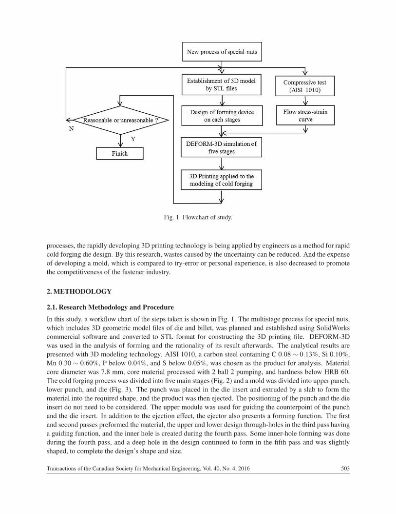
Fig. 1. Flowchart of study.
processes, the rapidly developing 3D printing technology is being applied by engineers as a method for rapidcold forging die design. By this research, wastes caused by the uncertainty can be reduced. And the expenseof developing a mold, which is compared to try-error or personal experience, is also decreased to promotethe competitiveness of the fastener industry.
2. METHODOLOGY
2.1. Research Methodology and Procedure
In this study, a workflow chart of the steps taken is shown in Fig. 1. The multistage process for special nuts,which includes 3D geometric model files of die and billet, was planned and established using SolidWorkscommercial software and converted to STL format for constructing the 3D printing file. DEFORM-3Dwas used in the analysis of forming and the rationality of its result afterwards. The analytical results arepresented with 3D modeling technology. AISI 1010, a carbon steel containing C 0.08 ∼ 0.13%, Si 0.10%,Mn 0.30 ∼ 0.60%, P below 0.04%, and S below 0.05%, was chosen as the product for analysis. Materialcore diameter was 7.8 mm, core material processed with 2 ball 2 pumping, and hardness below HRB 60.The cold forging process was divided into five main stages (Fig. 2) and a mold was divided into upper punch,lower punch, and die (Fig. 3). The punch was placed in the die insert and extruded by a slab to form thematerial into the required shape, and the product was then ejected. The positioning of the punch and the dieinsert do not need to be considered. The upper module was used for guiding the counterpoint of the punchand the die insert. In addition to the ejection effect, the ejector also presents a forming function. The firstand second passes preformed the material, the upper and lower design through-holes in the third pass havinga guiding function, and the inner hole is created during the fourth pass. Some inner-hole forming was doneduring the fourth pass, and a deep hole in the design continued to form in the fifth pass and was slightlyshaped, to complete the design’s shape and size.
Transactions of the Canadian Society for Mechanical Engineering, Vol. 40, No. 4, 2016 503

Fig. 2. Schematic diagram of five-stage cold forging.
Fig. 3. Schematic representation of cold forging process components.
2.2. Compression ExperimentSimulations should precede compression tests in order to acquire the load and strain (displacement) valuesof the material and estimate its stress-strain curve and forgeability flow curve (Fig. 4). An axisymmetriccylinder was placed under an axial (z-direction) load, the strain measured along the axis being axial strain.In practice, a universal testing machine would be used for the compression test. Load and strain values wererecorded for estimating engineering and the true stress/strain values. In general, after test specimen heightreductions reached 60%, failure values could not be continuously acquired by strain measurement becauseof excessive deformation. However, the failure values of more ductile materials cannot be acquired by thistest.
To obtain more accurate simulation results, a simple compression test was utilized for acquiring the truestress-true strain curve of the material for simulating fine fastener cold forging with Finite Element softwareDEFORM-3D. The equations for the compression test are shown below.
504 Transactions of the Canadian Society for Mechanical Engineering, Vol. 40, No. 4, 2016

Fig. 4. True-stress and true-strain curve of AISI 1010 and compressed specimens.
σ0 =PA0
, (1)
52ε0 =h0 −h
h0, (2)
where σ0 is the engineering stress, ε0: engineering strain, P: load, A0: original cross-sectional area, h0:original height, and h: height. The equations for true stress and true strain are shown below.
σt = σ0(1− r), (3)
εt = ln(1− r)−1, (4)
where σt is the true stress, εt : true strain, r: reduction, and r = h0−h/h0. The test specimen was compressedthrough a universal testing machine to acquire the loading schedule, which was further used for calculatingtrue stress and strain and constructing the flow stress curve using Grapher software program.
AISI 1010 test specimens were first cut into billets similar to the special nut; with external diameterand length ratio being about 1:1.5 (actual external diameter was 6 mm and height 9 mm). They werethen compression-tested with a universal testing machine under a pressure of 100 tons. Test specimenswere covered with lubricant (manganese dioxide) before compression so that the material was close toactual production line conditions. After compression (Fig. 4), test specimens were presented with strain testreductions of 30, 60, 75, and 90%. The loading, schedule, and times of the experiments were recorded andExcel used for calculating true stress and true strain. These values were then applied to Grapher for acquiringa power-law flow stress curve (Fig. 4) and flow stress equation σt = 633.63ε0.13, wherethe constant 633.63is the strength coefficient and 0.13 the work hardening exponent.
2.3. DEFORM SimulationDEFORM-3D Finite Element software was applied to simulate the cold forging of specialty nuts.DEFORM-3D was used for simulating and analyzing various passes, and the data for billet, punch, anddie as well as AISI material settings which were inputted, and the material’s property considered rigid-plastic. Young’s modulus and Poisson’s ratio were 210 GPa and 0.3, respectively, the flow stress equationacquired from the compression test showed σt = 633.63ε0.13, and constant shear friction factor m = 0.12.In terms of billet mesh setting, the minimum feature size of the billet was regarded as the basis and one-third of the feature size was the minimum side for convergence analysis. Forging loading was analyzedwhen the workpiece filled the die. When the loading difference in comparison to the previous number ofmeshes was within 0.01%, it was considered convergence. The punch speed in the process was assumed
Transactions of the Canadian Society for Mechanical Engineering, Vol. 40, No. 4, 2016 505
to be 420 mm/sec. The analytical results can be used for discussing the differences between the simulatedpass process and the field process and for evaluating the effective stress-strain, material flow, and reactionsof the simulated predicted material to the punch during forming. They are used as the evaluation standardfor punch and die strength in die design.
2.4. Printing Technology3D printing, or additive manufacturing (AM), is a quick forming technology for the direct manufacturingof 3D entities of any shape based on digital model files. Adhesive metal or plastic powder is applied in3D printing to construct an object through “additive manufacturing”. Different from traditional mechanicalprocessing, which often uses cutting or drilling (material reduction) for die production and industrial design,3D printing is often used for producing molds and is gradually applied to the direct manufacturing of prod-ucts. In particular, some high-value products (e.g. hip joint, teeth, and airplane parts) have been printed,revealing the popularity of 3D printing.
A digital material printer is generally used for 3D printing. Computer aided design (CAD) or computeranimation software is first used for establishing a mold, which is then “separated” into layered cross sections,and then the printer is guided for the printing. STL files are the coordination format between the designsoftware and the printer. An STL file simulates the surface of an object with triangular facets such thatsmaller triangular facets generate surfaces with higher resolution. After reading the cross-section STL files,the printer prints the layers with liquid, powder, or chips of material, which are further adhered to becomea solid physical object. Traditionally, it normally requires several hours to several days to produce a mold,depending on its size and complexity, whereas 3D printing can reduce the time to several hours, dependingon the size and complexity of the mold as well as printer efficiency. Traditional manufacturing, such asinjection molding, largely produces polymer products at lower costs, while 3D printing can more quickly,flexibly, and economically produce small quantities of products. A merely table-sized 3D printer can satisfythe demands of a designer or a development team for producing molds.
3. RESULTS AND DISCUSSION
This study used software simulation in an attempt to acquire distinct information after various passes offormation and present analytical results with 3D printing. The result of this study can be used for engineer-ing the design of a cold forging die to reduce time and development costs. Figures 5–9 show the analysesof special fasteners from first through fifth passes. Since stress affects the life of materials and the formingprocess and its results, higher stress presents higher hardening exponents that the material might not easily
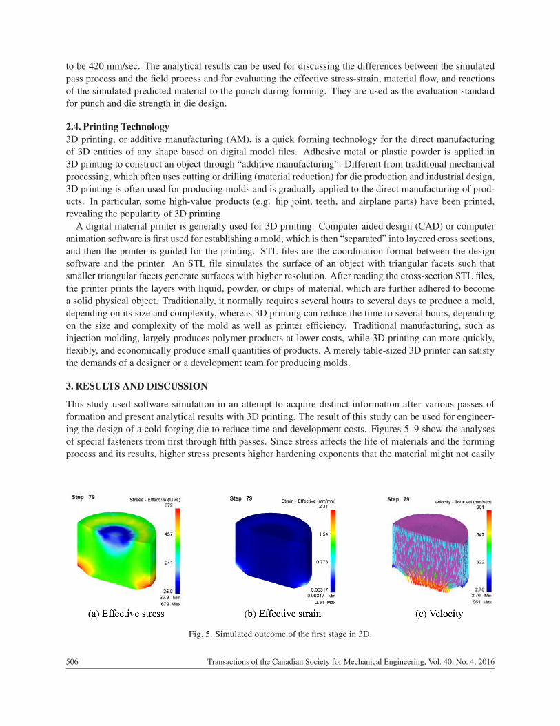
Fig. 5. Simulated outcome of the first stage in 3D.
506 Transactions of the Canadian Society for Mechanical Engineering, Vol. 40, No. 4, 2016

Fig. 6. Simulated outcome of the second stage in 3D.
Fig. 7. Simulated outcomes of the third stage in 3D.
process. Besides, stress is generally focused on corners in the processing that the fillet is designed for sothat the material can flow smoothly in a die. Strain information can help in understanding the deformationand the velocity field presents knowledge of material flow in the cavity during the compression process.Figure 5 shows first pass preforming, the maximum effective stress being 672 MPa and the maximumeffective strain 2.31 mm/mm. Deformation appeared on the turning corner in the die and the fastest velocityfield of 961 mm/sec appeared at the head. Figure 6 displays the second pass, where a guiding hole wasrequired to avoid buckling; the maximum effective stress of 672 MPa and maximum effective strain of2.78 mm/mm appeared on the upper and lower periphery and turning corner, respectively; and the maximumvelocity was 1,050 mm/sec. Figure 7 presents side forming in the third pass, when the maximum effectivestress of 675 MPa was concentrated on the material and the lower periphery, the maximum effective strainwas 7.31 mm/mm, and the highest velocity field 533 mm/sec. Figure 8 demonstrates that in the fourth pass,during which a deeper hole was made within the guiding hole during the second pass, that the bottom wasmade into an aperture shape with a punch and served as the guiding hole of the next pass. The fourth passproduced a maximum effective stress of 676 MPa, maximum effective strain of 5.74 mm/mm, and maximumvelocity field of 1000 mm/sec at the top of the periphery. Figure 9 depicts the fifth pass, when the guidinghole from the previous pass continued to form the deeper design size. The maximum effective stress onthe fifth pass was 675 MPa and maximum effective strain 4.90 mm/mm, appearing at the inner apertureand the periphery, and the maximum velocity field was 463 mm/sec. In the five-pass processing of specialfasteners, flash appeared on the second pass and the cavity at the third pass was oversized so that compressedmaterial could not reach design size. The material forming height was set at 11.97 mm in this pass while the
Transactions of the Canadian Society for Mechanical Engineering, Vol. 40, No. 4, 2016 507

Fig. 8. Simulated outcomes of the fourth stage in 3D.
Fig. 9. Simulation outcomes of the fifth stage in 3D.
maximum compressed height was merely 11.78 mm, a 0.19 mm difference. More compression would haveresulted in flash and smaller height. Deformation was so obvious after the third pass that folds appeared onthe bottom of the specialty fastener after compression.
This section analyzes the die formation for special shaped fasteners and simulates the forging load fromthe first stage to the fifth stage, as shown in Fig. 10. The forging load at various stages is shown below.In the workpiece reshaping at the first stage, the die approaches closed forging in which the forging load,159.37 kN (about 8.17%), is second small when comparing to other load. In the reshaping forming at thesecond stage, the engineering resembles the first stage, and the forging load reveals 271.43 kN (i.e. about13.91%). In the guiding function third stage, the forging load, 573.25 kN (i.e. about 29.38%), appears tolinearly increase as the material flow space is restricted. In the inner-hole forming with closed upsetting atthe fourth stage, the forging load, i.e. 869.82 kN (about 44.58%), is the largest among all stages. With thesame engineering as the third stage, the extending stroke at the fifth stage is 19.85 mm, and the forging load,77.15 kN (i.e. about 3.95%). It is obviously less than the other stages. Overall, the total forging load forspecial nuts from the first stage to the fifth stage shows 1951.02 kN.
Figure 11 displays the workpieces after DEFORM simulation at different stages, in which they are theresult of 3D printing with DEFORM 3D Finite Element Analysis. Figure 12 presents 3D printing of theupper punch, workpiece, die, and lower punch for the fourth stage. Obviously, good configuration agreementis illustrated between the simulation and 3D printing results. By the color representation in 3D printingresults, the dimension clearance between designed tooling and formed workpiece is easily found. Thisprocess allows engineers to gain a better understanding of the tooling design and development phase andtouches on parts that were previously just simulation results from DEFORM-3D forming software. The
508 Transactions of the Canadian Society for Mechanical Engineering, Vol. 40, No. 4, 2016

Fig. 10. Forging force versus stroke in each stage.
Fig. 11. 3D printing using products of the workpiece from first to fifth stages.
Fig. 12. 3D printing using products of the upper punch, lower punch, workpiece, die, and mold system at the fourthstage.
Transactions of the Canadian Society for Mechanical Engineering, Vol. 40, No. 4, 2016 509

results can help a multistage processing factory establish a cold forming capacity for the development ofnew products.
4. CONCLUSIONS
The development and design of a new automobile product begins with the production of high-cost parts,which are manufactured in mass production mechanically to reduce costs and enhance profits. Previousdesigns relied upon experience with similar products and often involve several iterations of failure. Losttime and costs can be made up with continuous production and improvement. Based on our preliminarynumerical analysis and 3D printing technique as applied to specialty shaped fasteners and relevant analysesare summarized below:
1. The application of DEFORM 3D enables the dynamic simulation of fastener forming during pre-design simulations in the development of new products.
2. Cold forming close upsetting generates a forging load of 869.82 kN (44.58%) at the fourth stage,which is the maximum for all stages of forming.
3. 3D printing technology with numerical simulation can be used in the design of process modeling toreduce human resource and production costs.
REFERENCES
1. O’Connell, M., Painter, B., Maul G. and Altan T., “Flashless closed-die upset forging-load estimation for optimalcold header selection”, Journal of Materials Processing Technology, Vol. 59, pp. 81–94, 1996.
2. Park, J.H., Kim, Y.H. and Jin, Y.E., “Experimental investigation of the forming parameters of the rotational upsetforging process”, Journal of Materials Processing Technology, Vol. 111, pp. 103–106, 2001.
3. Wu, C.-Y. and Hsu, Y.-C., “The influence of die shape on the flow deformation of extrusion forging”, Journal ofMaterials Processing Technology, Vol. 124, pp. 67–76, 2002.
4. Landre, J., Pertence,A., Cetlin, P.R., Rodrigues, J.M.C. and Martins, P.A.F. “On the utilization of ductile fracturecriteria in cold forging”, Finite Element in Analysis and Design, Vol. 39, pp. 175–186, 2003.
5. Min, D.-K. and Kim, M.-E., “A study on precision cold forging process improvements for the steering yoke ofautomobiles by the rigid-plastic finite-element method”, Journal of Materials Processing Technology, Vol. 138,pp. 339–342, 2003.
6. Hsia, S.-Y., “Optimization of microextrusion preforming using Taguchi method”, Mathematical Problem inEngineering, Vol. 2013, Article ID 305797, 2013.
7. Hsia, S.-Y. and Shih P.-Y., “Wear improvement of tools in the cold forging process for long hex flange nuts”,Materials, Vol. 8, pp. 6640–6657, 2015.
8. Hsia, S.-Y. and Chou, Y.-T., “Fabrication improvement of cold forging hexagonal nuts by computational analysisand experiment verification”, Mathematical Problem in Engineering, In press.
9. Hsia, S.-Y., “Improved manufacturing process for movable retaining pins using optimization method”, Transac-tions of the Canadian Society for Mechanical Engineering, Vol. 39, No. 2, pp. 1–18, 2015.
10. MacCormack, C. and Monaghan, J., “2D and 3D finite element analysis of a three stage forging sequence”,Journal of Materials Processing Technology, Vol. 127, pp. 48–56, 2002.
11. Joun, M.S., Lee, S.W. and Chung, J.H., “Finite element analysis of a multi-stage axisymmetric forging process”,International Journal of Machine Tools & Manufacture, Vol. 38, pp. 843–854, 1998.
510 Transactions of the Canadian Society for Mechanical Engineering, Vol. 40, No. 4, 2016