Embed Size (px)
Citation preview
1
Unit 3: Forging
Definition:
Forging is a metal working process in which useful shape is obtained in solid state by
hammering or pressing metal.
It is one of the oldest metalworking arts with its origin about some thousands of years
back. Some examples of shapes obtained by forging process: Crane hook, connecting rod of IC
engine, spanner, gear blanks ..etc.
Different Forging Operations
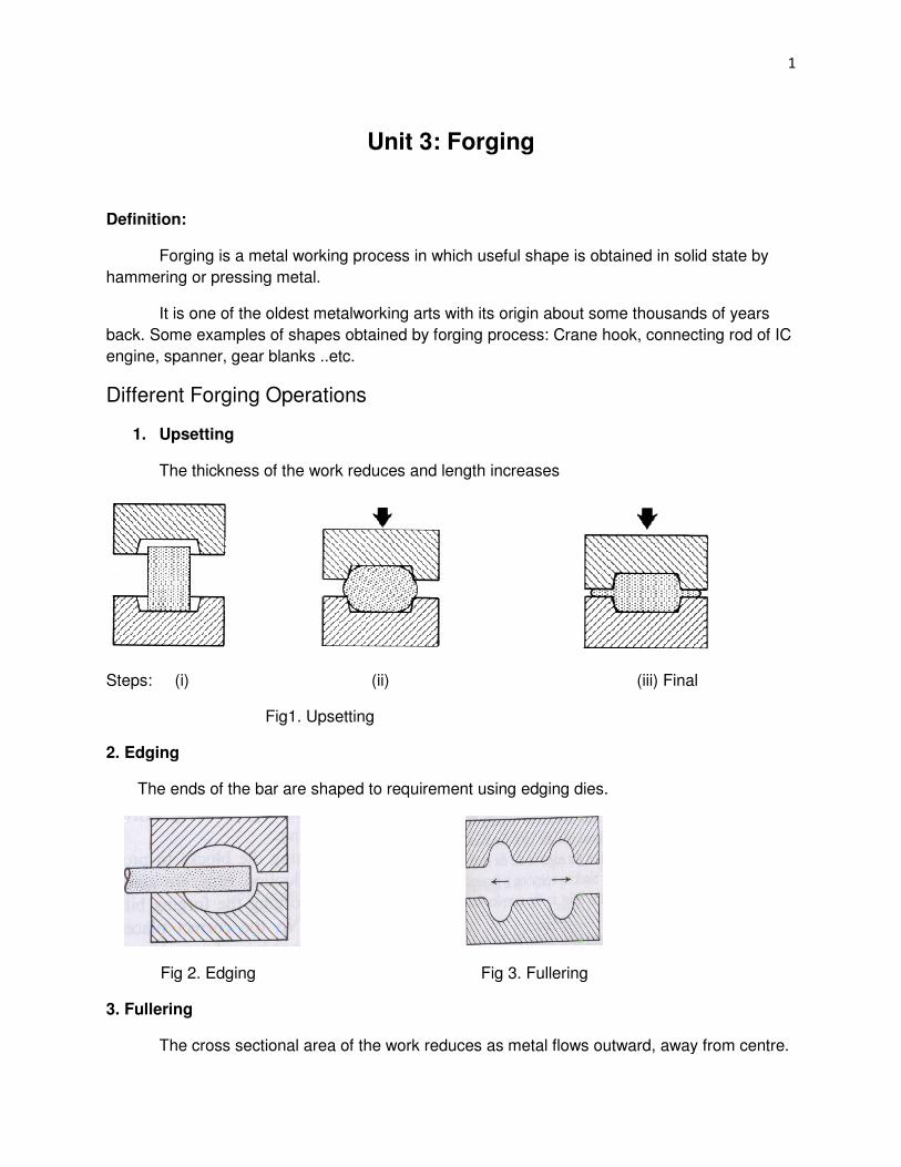
1. Upsetting
The thickness of the work reduces and length increases
Steps: (i) (ii) (iii) Final
Fig1. Upsetting
2. Edging
The ends of the bar are shaped to requirement using edging dies.
Fig 2. Edging Fig 3. Fullering
3. Fullering
The cross sectional area of the work reduces as metal flows outward, away from centre.
2
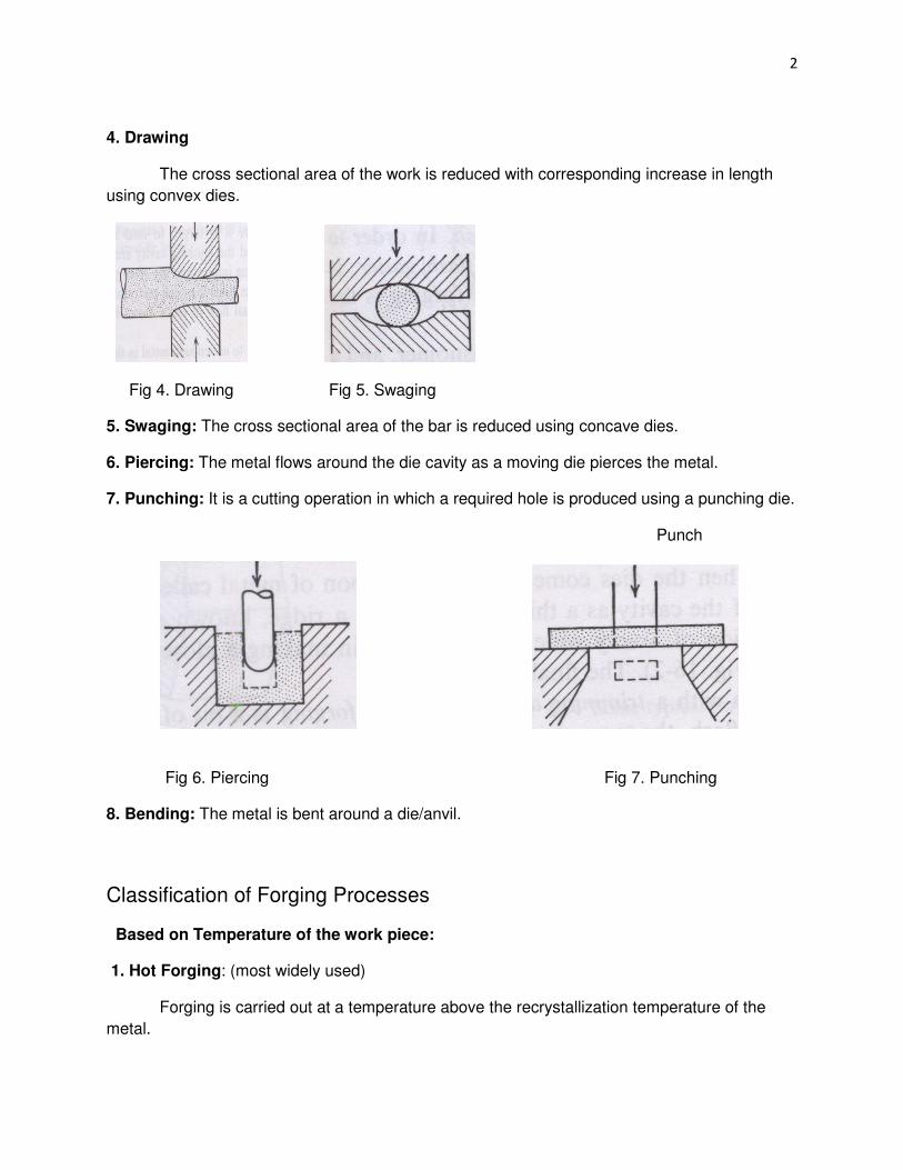
4. Drawing
The cross sectional area of the work is reduced with corresponding increase in length
using convex dies.
Fig 4. Drawing Fig 5. Swaging
5. Swaging: The cross sectional area of the bar is reduced using concave dies.
6. Piercing: The metal flows around the die cavity as a moving die pierces the metal.
7. Punching: It is a cutting operation in which a required hole is produced using a punching die.
Punch
Fig 6. Piercing Fig 7. Punching
8. Bending: The metal is bent around a die/anvil.
Classification of Forging Processes
Based on Temperature of the work piece:
1. Hot Forging: (most widely used)
Forging is carried out at a temperature above the recrystallization temperature of the
metal.

3
Advantages:
• High strain rates and hence easy flow of the metal
• Recrystallization and recovery are possible
• Forces required are less
Disadvantages of Hot Working:
• Lubrication is difficult at high temperatures
• Oxidation and scaling occur on the work
• Poor surface finish
• Dies must withstand high working temperature
2. Cold Forging:
Forging is carried out at a temperature below the recrystallization temperature of the
metal.
Advantages:
• Less friction between die surface and work piece
• Lubrication is easy
• No oxidation or scaling on the work
• Good surface finish
Disadvantages of Cold Working:
• Low strain rates, hence less reduction per pass.
• Recrystallization and recovery do not occur.
• Hence, annealing is required for further deformation in subsequent cycles.
• Forces required are high.
Classification of Forging Processes Based on Arrangement of Dies:
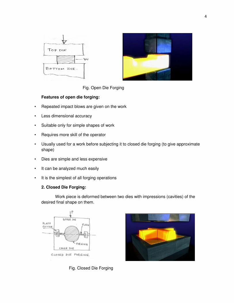
1. Open Die Forging: Flat dies of simple shape are used.
4
Fig. Open Die Forging
Features of open die forging:
• Repeated impact blows are given on the work
• Less dimensional accuracy
• Suitable only for simple shapes of work
• Requires more skill of the operator
• Usually used for a work before subjecting it to closed die forging (to give approximate
shape)
• Dies are simple and less expensive
• It can be analyzed much easily
• It is the simplest of all forging operations
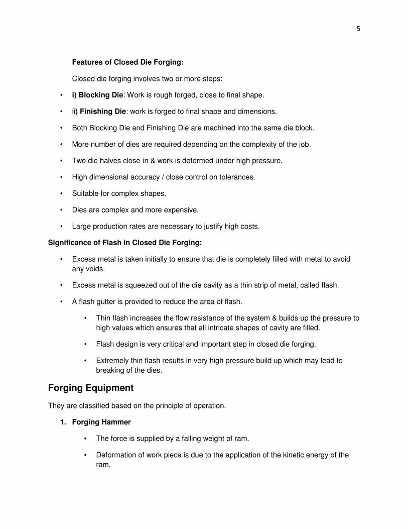
2. Closed Die Forging:
Work piece is deformed between two dies with impressions (cavities) of the
desired final shape on them.
Fig. Closed Die Forging
5
Features of Closed Die Forging:
Closed die forging involves two or more steps:
• i) Blocking Die: Work is rough forged, close to final shape.
• ii) Finishing Die: work is forged to final shape and dimensions.
• Both Blocking Die and Finishing Die are machined into the same die block.
• More number of dies are required depending on the complexity of the job.
• Two die halves close-in & work is deformed under high pressure.
• High dimensional accuracy / close control on tolerances.
• Suitable for complex shapes.
• Dies are complex and more expensive.
• Large production rates are necessary to justify high costs.
Significance of Flash in Closed Die Forging:
• Excess metal is taken initially to ensure that die is completely filled with metal to avoid
any voids.
• Excess metal is squeezed out of the die cavity as a thin strip of metal, called flash.
• A flash gutter is provided to reduce the area of flash.
• Thin flash increases the flow resistance of the system & builds up the pressure to
high values which ensures that all intricate shapes of cavity are filled.
• Flash design is very critical and important step in closed die forging.
• Extremely thin flash results in very high pressure build up which may lead to
breaking of the dies.
Forging Equipment
They are classified based on the principle of operation.
1. Forging Hammer
• The force is supplied by a falling weight of ram.
• Deformation of work piece is due to the application of the kinetic energy of the
ram.

6
Types of Forging Press
i) Mechanical board hammer:
• It is a stroke restricted machine.
• Repeatedly the board (weight) is raised by rolls and is dropped on the die.
• Rating is in terms of weight of the ram and energy delivered.
Fig. Mechanical Board Hammer Fig. Steam Hammer
ii) Steam Hammer (Power Hammer) Range: 5 kN to 200 kN
• It uses steam in a piston and cylinder arrangement.
• It has greater forging capacity.
• It can produce forgings ranging from a few kgs to several tonnes.
• Preferred in closed die forging
The total energy supplied in a blow:
It is given by : W=1/2mv2 + pAH = (mg + pA)
Where m= mass of ram
v= velocity of ram at the start of deformation
g= acceleration due to gravity
p= air/ steam pressure on ram on down stroke
7
A= area of ram cylinder
H= height of ram drop
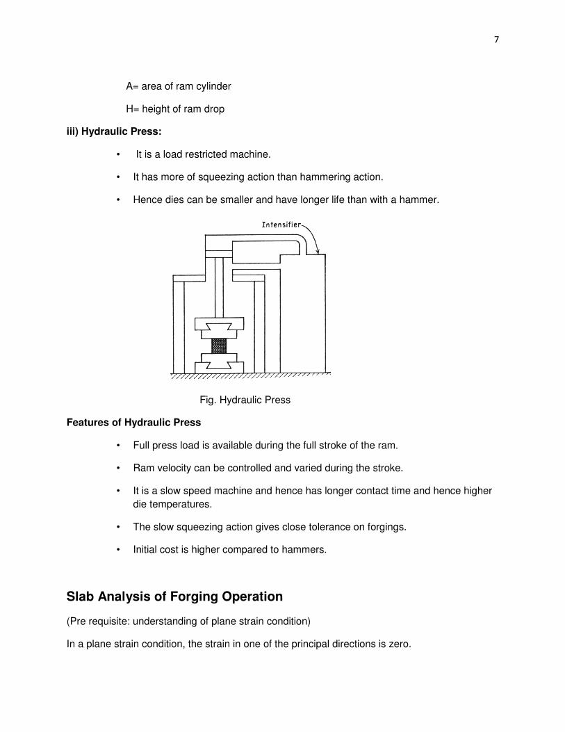
iii) Hydraulic Press:
• It is a load restricted machine.
• It has more of squeezing action than hammering action.
• Hence dies can be smaller and have longer life than with a hammer.
Fig. Hydraulic Press
Features of Hydraulic Press
• Full press load is available during the full stroke of the ram.
• Ram velocity can be controlled and varied during the stroke.
• It is a slow speed machine and hence has longer contact time and hence higher
die temperatures.
• The slow squeezing action gives close tolerance on forgings.
• Initial cost is higher compared to hammers.
Slab Analysis of Forging Operation
(Pre requisite: understanding of plane strain condition)
In a plane strain condition, the strain in one of the principal directions is zero.
8
During a forging process,
• the thickness of the work piece decreases
• the length of the work piece decreases
• The width remains unchanged
In a general condition of stress:
Let σ1,σ2, and σ3 be the principal stresses,
ε1, ε2 and ε3 be the principal strains.
In a plane strain condition, ε2=0 (as width remains constant).
In this condition, it can be shown that the principal stress σ2, acting in a direction where
ε2=0, is the algebraic mean of the other two principal stresses.
This means,
σ2 = (σ1 + σ3)/2
Applying Von-Mises’ criteria for yielding, it can be shown that:
(σ1 - σ3) = (2/√3) σ0
= σ0/ (pronounced sigma not prime)
= yield stress under plane strain condition
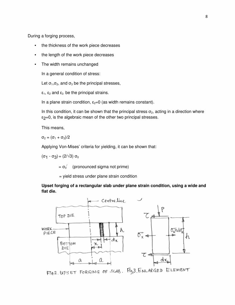
Upset forging of a rectangular slab under plane strain condition, using a wide and
flat die.
9
Consider a rectangular slab as shown in the above figure.
Let t = thickness of the work ( decreases during forging)
L = length of the work (increases during forging)
W = width of the work (remains constant)
Consider an elemental volume in the work piece with length dx at a distance x from the
centerline.
The stresses acting on the elemental volume are :
i) P = forging pressure
ii) σx= Longitudinal stress due to lateral flow of the metal
iii) =Shear stress due to friction between work and die surfaces
Under the equilibrium conditions, the summation of forces acting in a longitudinal
direction must be zero.
Applying the above condition and conditions of plane strain, it can be shown that:
The above equation is solved for different conditions as follows:
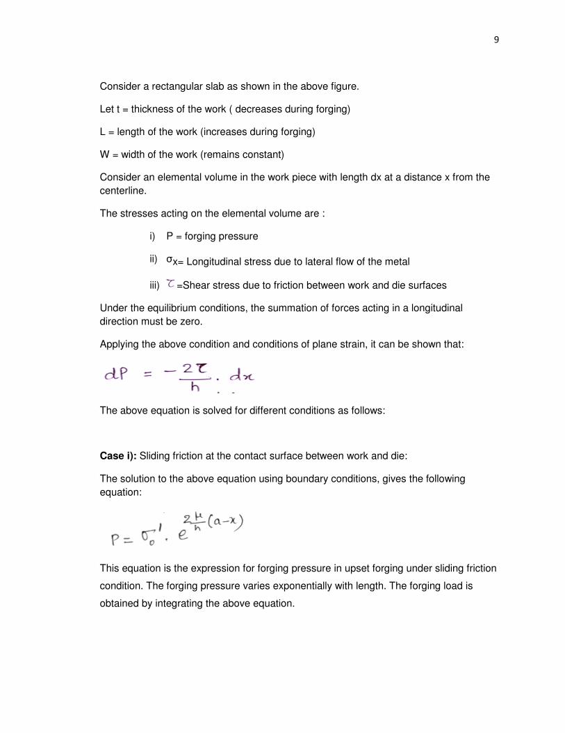
Case i): Sliding friction at the contact surface between work and die:
The solution to the above equation using boundary conditions, gives the following
equation:
This equation is the expression for forging pressure in upset forging under sliding friction
condition. The forging pressure varies exponentially with length. The forging load is
obtained by integrating the above equation.

10
Friction Hill for Sliding Friction Case:
Fig. Friction Hill in Sliding Friction Condition
Case ii): Sticking friction at the work – die interface: This is a severe condition of friction.
The solution to the general differential equation in this case with appropriate
boundary conditions yields the equation:
The equation is a linear one, indicating linear variation of forging pressure with length.
The forging load in this case is obtained by integrating the above equation.
11
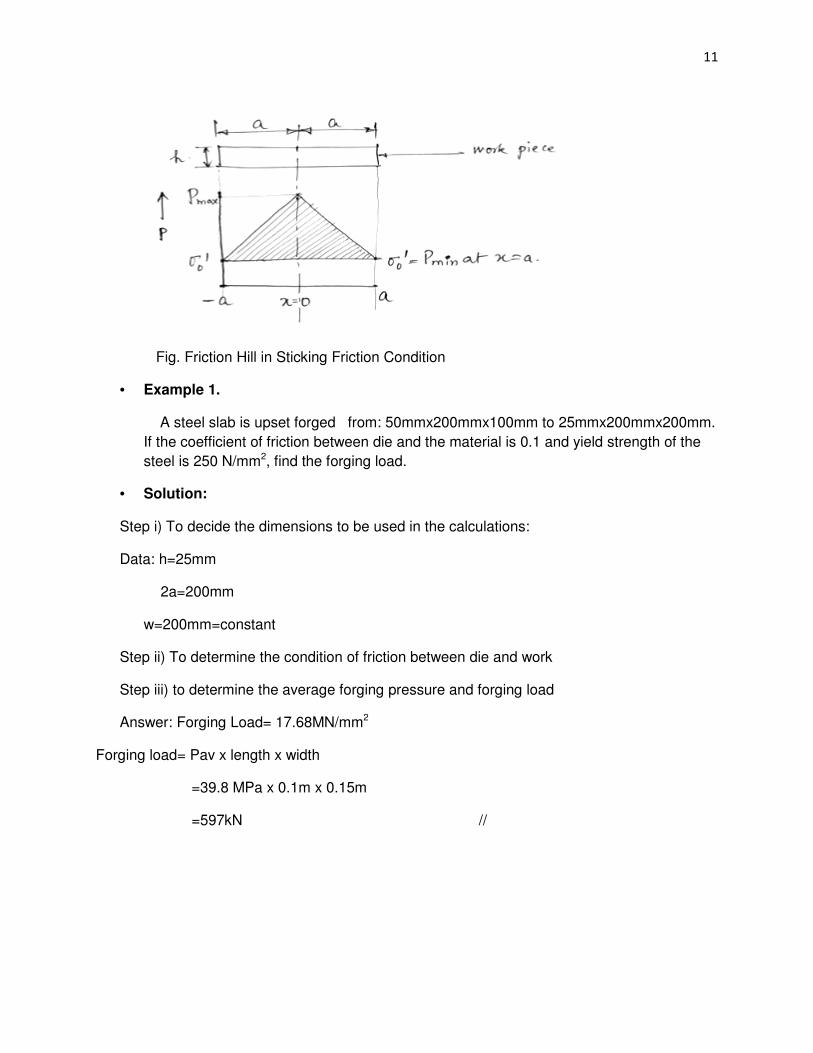
Fig. Friction Hill in Sticking Friction Condition
• Example 1.
A steel slab is upset forged from: 50mmx200mmx100mm to 25mmx200mmx200mm.
If the coefficient of friction between die and the material is 0.1 and yield strength of the
steel is 250 N/mm2, find the forging load.
• Solution:
Step i) To decide the dimensions to be used in the calculations:
Data: h=25mm
2a=200mm
w=200mm=constant
Step ii) To determine the condition of friction between die and work
Step iii) to determine the average forging pressure and forging load
Answer: Forging Load= 17.68MN/mm2
Forging load= Pav x length x width
=39.8 MPa x 0.1m x 0.15m
=597kN //

12
Upset forging of a circular disc in open die forging
Analysis involves cylindrical coordinates
The stresses acting on an elemental volume in a disc are:
σr = radial stress responsible for increase in the diameter of the disc
σθ = circumferential or tangential stress increasing the circumference of the disc
Both σr and σθ are TENSILE in nature
Always,
σr = σθ
This is called cylindrical state of stress
FRICTION HILL
Both forging pressure P and longitudinal stress (σx) build up to a maximum value at the centre
of the plate(work), and reduce to a minimum value at the edge(end) of the plate. When this
variation in P & ( σx ) is plotted over the entire length, L= 2a, a peak exists at the centre,
resembling a “hill”.
This plot is called as friction hill.
13
NEUTRAL SURFACE
During forging , the metal is stationary at the centre line of the plate which defines the
neutral surface.
The flow of metal is always outwards, away from this neutral surface.
It is difficult to establish the neutral surface in a forging with a complex geometry.
FACTORS AFFECTING FRICTION HILL
1. Nature of friction at the die/ work interface
a. Sliding Friction : exponential variation
b. Sticking Friction : linear (more severe conditions of friction)
c. Mixed Friction : linear at the middle where sticking friction exists and exponential at
the edge where sliding friction exists
2. Lubrication :(lubricants used : graphite powder, liquid glass)
- If lubricant film is maintained, it gives sliding friction
- Possible in cold forging
- Under condition of high forging pressure and high temperature the lubricant is
squeezed out or burnt
- Leads to stitching friction and normally in hot forging
3. Finish on die surface: roughness on die adds to friction.
- Proper selection of die material to retain finish is necessary.
4. Working temperature
Hot Forging : lubrication difficult, easy flow of metal
Cold “ : lubrication easy, less plastic flow
5. Nature of work surface:
- Smooth/clean surface – less friction
- Scales/dirt/rough surface – more friction
14
FORGING PRESSURE / LOAD IN CLOSED DIE FORGING (CFD)
The deformation in closed die forging is highly complex and hence designing dies and
intermediate steps is very critical and requires high skill.
The main objectives are: – complete die fill and closed dimensional tolerance. Important
factors to be considered in CDF are:
1. Flash design : flash controls die fill and creates high forging loads
2. Proper understanding of the flow stress of the material: ensures successful forging
operation
3. Frictional conditions
4. Optimal geometry of the die: Result of proper understanding of flow stress, friction
conditions and flow of the metal in the die
5. To prevent rapid cooling of the work piece by cold die’s :
- die’s are preheated for many difficult aerospace applications- called isothermal
heating
- Results in lower flow stress and forging loads
- Gives complete die fill and close dimensional tolerances
The design of a workpiece (part) made by CDF involves the prediction of the following :
1. Vol. and wt. of the workpiece
2. No. of pre-forming or intermediate steps and their configuration
3. Flash dimension in finishing die
4. Load & en-requirement for each operation
Forging load in CDF:
Prediction of forging load in CDF is quite difficult because of complexity involved
Usual prediction methods are:
1. Past Experience:
To estimate forging load of a new part/geometry: using information available from
previous forging s of similar materials and shapes is used.
15
2. Using empirical relations:
One of the widely used equations is:
P = σ.AtC1
Where σ = effective true stress
At = cross sectional area of the forging at the parting line, including the flash
Where C1 = a constant, depends on the complexity of the forging
C1 = 1.2 to 2.5 for upsetting a cylinder between flat dies
= 3 to 8 for simple closed die forging
= 8 to 12 for more complex shapes
3. Slab Analysis- with suitable modifications for situations in CDF
Basic approach:
- The forging required is divided into simple geometric shapes, which are separately
treated by slab analysis
- The addition of all the loads of parts gives the total forging load
DIE DESIGN PARAMETERS
- Die design depends on the forging required and its design requires the knowledge of:
i. Strength and ductility of work piece materials
ii. Sensitivity of the materials to the rate of deformation and temperature
iii. Frictional characteristics
iv. Shape and complexity of work piece
v. Die distortion under high forging loads- for close dimensional tolerance
16
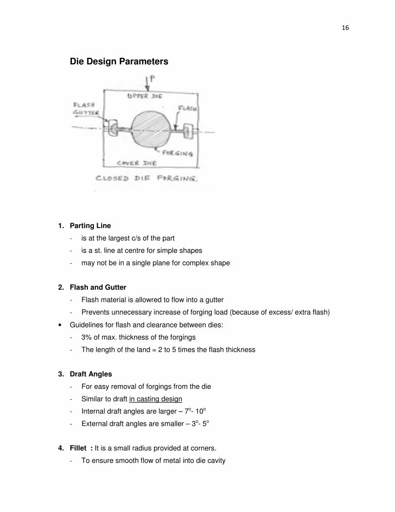
Die Design Parameters
1. Parting Line
- is at the largest c/s of the part
- is a st. line at centre for simple shapes
- may not be in a single plane for complex shape
2. Flash and Gutter
- Flash material is allowred to flow into a gutter
- Prevents unnecessary increase of forging load (because of excess/ extra flash)
• Guidelines for flash and clearance between dies:
- 3% of max. thickness of the forgings
- The length of the land = 2 to 5 times the flash thickness
3. Draft Angles
- For easy removal of forgings from the die
- Similar to draft in casting design
- Internal draft angles are larger – 7o- 10o
- External draft angles are smaller – 3o- 5o
4. Fillet : It is a small radius provided at corners.
- To ensure smooth flow of metal into die cavity
17
- To improve die life
- As a general rule, should be as large as possible
• Small fillet radii lead to;
- Improper metal flow
- Rapid wear of die
- Fatigue cracking of dies
5. Die material : requirements are
- Strength and toughness at elevated temperature
- Hardenability and ability to harden uniformly
- Resistance to mechanical and thermal shocks
- Wear resistance – to resist abrasion wear due to scales present on work piece
Selection of proper die material depends on :
• Die size
• Composition and properties of work piece
• Complexity of shape- no of performing steps
• Forging temperature
• Type of forging operation
• Cost of die material
• No. of forgings required
• Heat transfer from work piece to dies
• Die materials used:
• Tool and die steels with Cr, Ni, Mo, Va
Die Manufacturing: It consists of the following steps:
• -- Initially castings
• – then forged
• – finally machined and finished to required shape and surface finish
18
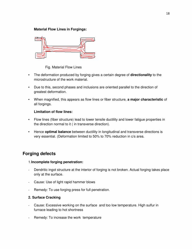
Material Flow Lines in Forgings:
Fig. Material Flow Lines
• The deformation produced by forging gives a certain degree of directionality to the
microstructure of the work material.
• Due to this, second phases and inclusions are oriented parallel to the direction of
greatest deformation.
• When magnified, this appears as flow lines or fiber structure, a major characteristic of
all forgings.
Limitation of flow lines:
• Flow lines (fiber structure) lead to lower tensile ductility and lower fatigue properties in
the direction normal to it ( in transverse direction).
• Hence optimal balance between ductility in longitudinal and transverse directions is
very essential. (Deformation limited to 50% to 70% reduction in c/s area.
Forging defects
1.Incomplete forging penetration:
- Dendritic ingot structure at the interior of forging is not broken. Actual forging takes place
only at the surface.
- Cause: Use of light rapid hammer blows
- Remedy: To use forging press for full penetration.
2. Surface Cracking
- Cause: Excessive working on the surface and too low temperature. High sulfur in
furnace leading to hot shortness
- Remedy: To increase the work temperature

19
3.Cracking at the flash:
- This crack penetrates into the interior after flash is trimmed off.
- Cause: Very thin flash
- Remedy:-Increasing flash thickness, relocating the flash to a less critical region of the
forging, hot trimming and stress relieving.
4. Cold shut (Fold)
• Two surfaces of metal fold against each other without welding completely
• Cause: Sharp corner (less fillet), excessive chilling, high friction
• Remedy: increase fillet radius on the die
5.Scale pockets and Underfills:
• They are loose scale/ lubricant residue which accumulate in deep recesses of the die.
• Cause: Incomplete descaling of the work
• Remedy: Proper decaling of work prior to forging
6. Internal cracks
Cause: Secondary tensile stresses developed during forging
Remedy: Proper die design
Residual stresses in Forging:
Causes: Inhomogeneous deformation and improper cooling (quenching) of forging.
Remedy: Slow cooling of the forging in a furnace or under ash cover over a period of time.