Embed Size (px)
Citation preview
SIMTech Technical Report (PT/01/042/PMF)
Precision Cold Forging – Innovative Methods for Working Pressure Reduction
Steven Tong Dr Tsuyoshi Muramatsu
Dr Choy Chee Mun Zhang Su Xia
M Enggalhardjo
(Precision Metal Forming Group, Process Technology Division, 2001)
Precision Cold Forging – Innovative Methods for Working Pressure Reduction PT/01/042/PMF
Keywords: Forging; Working load; Finite element; Grain flow; Process monitoring 1
1 BACKGROUND Cold forging is a process in which the shape of metal is changed, by mechanical forces only, using the ductile properties of metal. In forging, a metal work piece is plastically deformed by pressing, squeezing, or hammering forces – at temperatures ranging from ambient (cold forging) to 1,500oC (hot forging). During forging, the material should have sufficient flow properties and work at the upper limit of the material’s potential strength so as to fill the die cavity shape without resulting in cracks in the material. The properties of the worked metal can be greatly enhanced by selecting the proper types and sequence of operations. The controlled process of deformation that takes place imparts exceptional metallurgical soundness and mechanical properties to the forging – structural integrity, impact strength, fracture toughness, fatigue life and uniformity. Forging is a cost effective way to produce net-shape or near-net-shape components. Virtually all metals can be forged. This makes an extensive range of physical and mechanical properties available in products with the highest structural integrity. Forgings are used in high performance, high strength, and high reliability applications where tension, stress, load, and human safety are critical considerations. They are also employed in a wide range of demanding environments, including highly corrosive, and extreme temperatures and pressures. 1.1 Trends in Forging One of the most important subjects of research and development in forging is precision forging where high accuracy, complex and net shape components can be produced [1]. Cold forging has high potential to reduce manufacturing cost. If the work material could be completely filled up into the die cavity, desired accuracy of the product could be achieved, and hence high productivity could be envisaged. However, the complete filling up of material into the die cavity is quite difficult because of high
working pressure [2]. The process often involves uni/multi-axial loading, large deformation and substantial work hardening of the work material in order to achieve the required shape. Hence, punch and die used in cold forging often need to withstand forming stress up to 1500 N/mm2. 1.2 Basic Consideration (Principles) The working pressure (loads) in forging consists of the following three principle components. 1. Resistance for ideal deformation 2. Frictional resistance 3. Resistance for redundant work
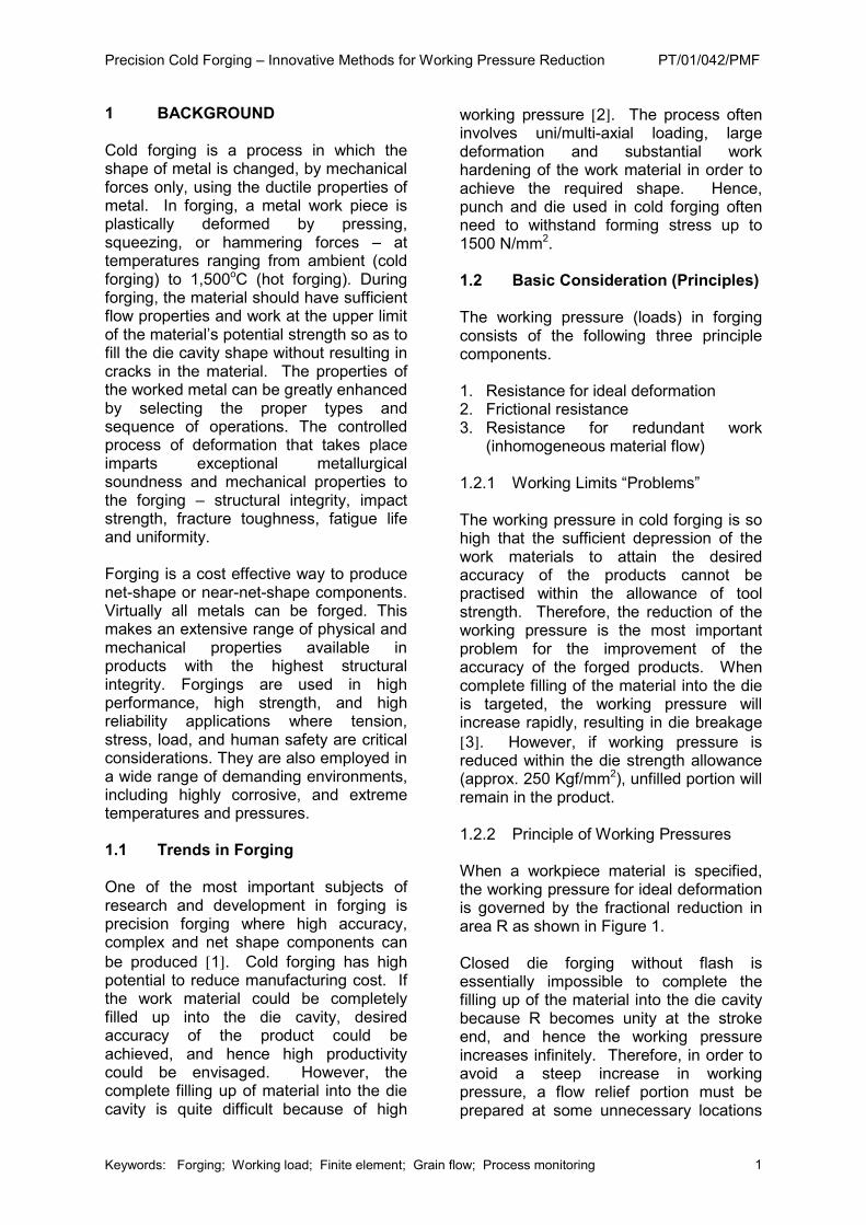
(inhomogeneous material flow) 1.2.1 Working Limits “Problems” The working pressure in cold forging is so high that the sufficient depression of the work materials to attain the desired accuracy of the products cannot be practised within the allowance of tool strength. Therefore, the reduction of the working pressure is the most important problem for the improvement of the accuracy of the forged products. When complete filling of the material into the die is targeted, the working pressure will increase rapidly, resulting in die breakage [3]. However, if working pressure is reduced within the die strength allowance (approx. 250 Kgf/mm2), unfilled portion will remain in the product. 1.2.2 Principle of Working Pressures When a workpiece material is specified, the working pressure for ideal deformation is governed by the fractional reduction in area R as shown in Figure 1. Closed die forging without flash is essentially impossible to complete the filling up of the material into the die cavity because R becomes unity at the stroke end, and hence the working pressure increases infinitely. Therefore, in order to avoid a steep increase in working pressure, a flow relief portion must be prepared at some unnecessary locations
Precision Cold Forging – Innovative Methods for Working Pressure Reduction PT/01/042/PMF
2
of the contour even when the complete filling up of material is attained at necessary contour portions. Figure.1: Influence of fractional reduction in area on extrusion pressure Pm 1.2.3 Counter Measure Complete filling of the material into the die cavity will require some techniques to ensure the die strength is not exceeded. The methods aim at simultaneous completion of filling up to die cavity at all contour portions of products. As already mentioned, the working load rises infinitely at the moment when perfect filling up is completed. Therefore, working stroke must be stopped just before the moment and the final filling portion must be finished later. This final filling up portion must be selected to a location which is easy to finish by a simple machining. In this study, the reduction of working pressure for cold forging by three techniques were evaluated and tested. They were: 1. Pre-chamfering 2. Spread Extrusion 3. Relieve Axis 2 OBJECTIVES The objectives of the project are to: 1) Establish newer methods in process
design for the reduction of forming pressure in cold forging.
2) Investigate innovative techniques in die design to reduce the forming pressure in cold forging
3) Evaluate the state-of-the-art hydraulic closed loop technology by using hydro-pneumatic pressure control system to obtain precision punch displacement and quality punch force profiles. This will allow another alternative technique to forming pressure reduction. The reduction of forming pressure is useful to improve die life and accuracy of forming net shape components.
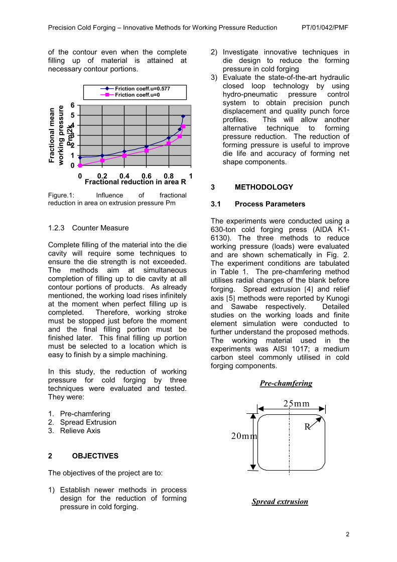
3 METHODOLOGY 3.1 Process Parameters The experiments were conducted using a 630-ton cold forging press (AIDA K1-6130). The three methods to reduce working pressure (loads) were evaluated and are shown schematically in Fig. 2. The experiment conditions are tabulated in Table 1. The pre-chamfering method utilises radial changes of the blank before forging. Spread extrusion [4] and relief axis [5] methods were reported by Kunogi and Sawabe respectively. Detailed studies on the working loads and finite element simulation were conducted to further understand the proposed methods. The working material used in the experiments was AISI 1017; a medium carbon steel commonly utilised in cold forging components.
Pre-chamfering
25mm
20mm R
Spread extrusion
0123456
0 0.2 0.4 0.6 0.8 1Fractional reduction in area R
Frac
tiona
l mea
n w
orki
ng p
ress
ure
Pm/2
k
Friction coeff.u=0.577Friction coeff.u=0
Precision Cold Forging – Innovative Methods for Working Pressure Reduction PT/01/042/PMF
3
Punchtravel
Testmaterial
Punch diam. D
∆ HResidual dieheight
D’=17.68mm
D”=25mm
Relief axis
Punchdiameter, D
Reliefclearance,Rc
Testmaterial
Punchtravel
d’=12.5mm
D”=25mm
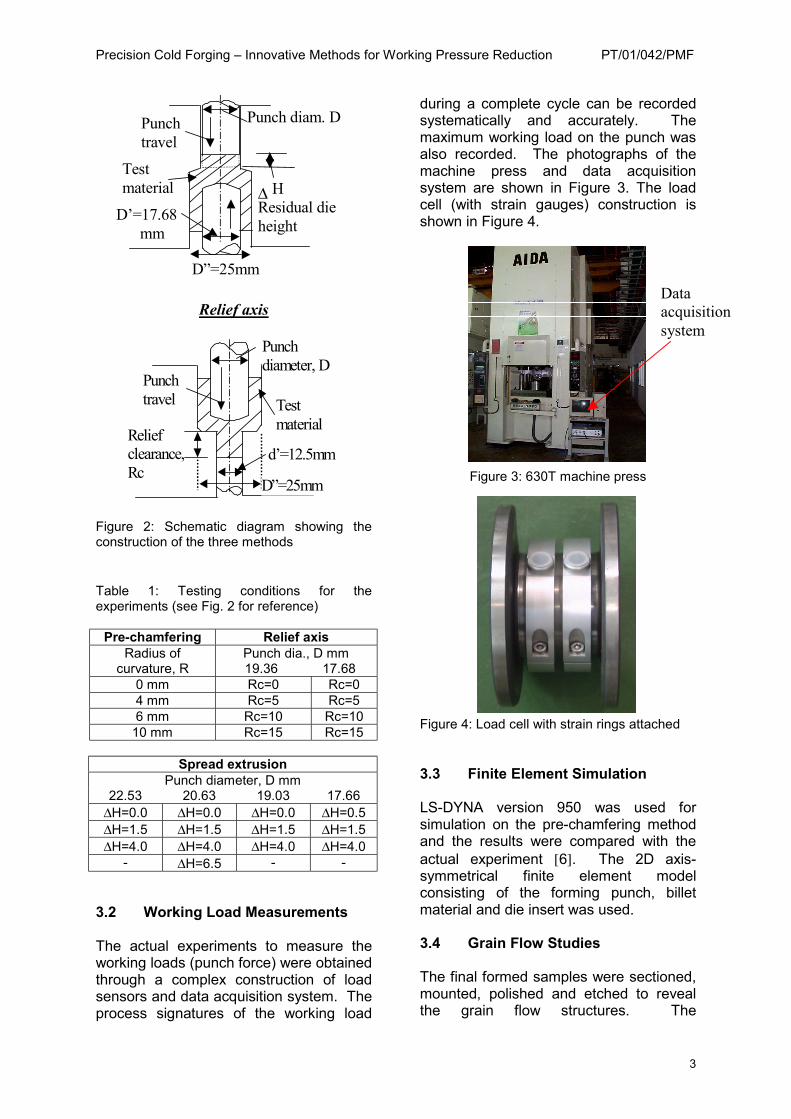
Figure 2: Schematic diagram showing the construction of the three methods Table 1: Testing conditions for the experiments (see Fig. 2 for reference)
Pre-chamfering Relief axis Radius of
curvature, R Punch dia., D mm
19.36 17.68 0 mm Rc=0 Rc=0 4 mm Rc=5 Rc=5 6 mm Rc=10 Rc=10
10 mm Rc=15 Rc=15
Spread extrusion Punch diameter, D mm
22.53 20.63 19.03 17.66 ∆H=0.0 ∆H=0.0 ∆H=0.0 ∆H=0.5 ∆H=1.5 ∆H=1.5 ∆H=1.5 ∆H=1.5 ∆H=4.0 ∆H=4.0 ∆H=4.0 ∆H=4.0
- ∆H=6.5 - - 3.2 Working Load Measurements The actual experiments to measure the working loads (punch force) were obtained through a complex construction of load sensors and data acquisition system. The process signatures of the working load
during a complete cycle can be recorded systematically and accurately. The maximum working load on the punch was also recorded. The photographs of the machine press and data acquisition system are shown in Figure 3. The load cell (with strain gauges) construction is shown in Figure 4.
Figure 3: 630T machine press
Figure 4: Load cell with strain rings attached 3.3 Finite Element Simulation LS-DYNA version 950 was used for simulation on the pre-chamfering method and the results were compared with the actual experiment [6]. The 2D axis-symmetrical finite element model consisting of the forming punch, billet material and die insert was used. 3.4 Grain Flow Studies The final formed samples were sectioned, mounted, polished and etched to reveal the grain flow structures. The
Data acquisition system
Precision Cold Forging – Innovative Methods for Working Pressure Reduction PT/01/042/PMF
4
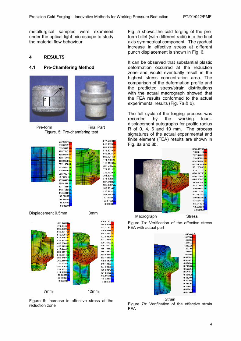
metallurgical samples were examined under the optical light microscope to study the material flow behaviour. 4 RESULTS 4.1 Pre-Chamfering Method
Pre-form Final Part Figure. 5: Pre-chamfering test
Displacement 0.5mm 3mm
7mm 12mm
Figure 6: Increase in effective stress at the reduction zone
Fig. 5 shows the cold forging of the pre-form billet (with different radii) into the final axis symmetrical component. The gradual increase in effective stress at different punch displacement is shown in Fig. 6. It can be observed that substantial plastic deformation occurred at the reduction zone and would eventually result in the highest stress concentration area. The comparison of the deformation profile and the predicted stress/strain distributions with the actual macrograph showed that the FEA results conformed to the actual experimental results (Fig. 7a & b). The full cycle of the forging process was recorded by the working load–displacement autographs for profile radius R of 0, 4, 6 and 10 mm. The process signatures of the actual experimental and finite element (FEA) results are shown in Fig. 8a and 8b.
Macrograph Stress
Figure 7a: Verification of the effective stress FEA with actual part
Strain Figure 7b: Verification of the effective strain FEA
R
Precision Cold Forging – Innovative Methods for Working Pressure Reduction PT/01/042/PMF
5
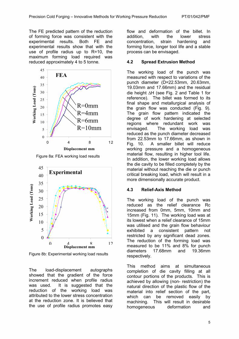
The FE predicted pattern of the reduction of forming force was consistent with the experimental results. Both FE and experimental results show that with the use of profile radius up to R=10, the maximum forming load required was reduced approximately 4 to 5 tonne.
Figure 8a: FEA working load results
Figure 8b: Experimental working load results The load-displacement autographs showed that the gradient of the force increment reduced when profile radius was used. It is suggested that the reduction of the working load was attributed to the lower stress concentration at the reduction zone. It is believed that the use of profile radius promotes easy
flow and deformation of the billet. In addition, with the lower stress concentration, strain hardening and forming force, longer tool life and a stable process can be envisaged. 4.2 Spread Extrusion Method The working load of the punch was measured with respect to variations of the punch diameter (D=22.53mm, 20.63mm, 19.03mm and 17.66mm) and the residual die height ∆H (see Fig. 2 and Table 1 for reference). The billet was formed to its final shape and metallurgical analysis of the grain flow was conducted (Fig. 9). The grain flow pattern indicated the degree of work hardening at selected regions where redundant work was envisaged. The working load was reduced as the punch diameter decreased from 22.53mm to 17.66mm, as shown in Fig. 10. A smaller billet will reduce working pressure and a homogeneous material flow, resulting in higher tool life. In addition, the lower working load allows the die cavity to be filled completely by the material without reaching the die or punch critical breaking load, which will result in a more dimensionally accurate product. 4.3 Relief-Axis Method The working load of the punch was reduced as the relief clearance Rc increased from 0mm, 5mm, 10mm and 15mm (Fig. 11). The working load was at its lowest when a relief clearance of 15mm was utilised and the grain flow behaviour exhibited a consistent pattern not restricted by any significant dead zones. The reduction of the forming load was measured to be 11% and 8% for punch diameters 17.68mm and 19.36mm respectively. This method aims at simultaneous completion of die cavity filling at all contour portions of the products. This is achieved by allowing (non- restriction) the natural direction of the plastic flow of the material into relief section of the part, which can be removed easily by machining. This will result in desirable homogeneous deformation and
0 4 8 120 5
10 15 20 25 30 35 40 45
Experimental
Displacement mm
Wor
king
Loa
d (T
ons)
W
orki
ng L
oad
(Ton
s)
0
5
10
15
20
25
30
35
40
45
0 4 8 12
R=0mm R=4mm R=6mm R=10mm
FEA
Displacement mm
Precision Cold Forging – Innovative Methods for Working Pressure Reduction PT/01/042/PMF
6
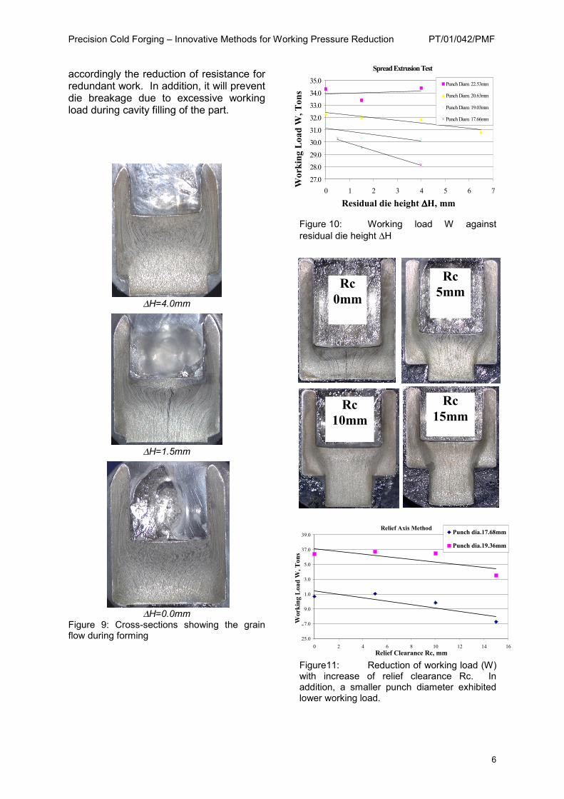
accordingly the reduction of resistance for redundant work. In addition, it will prevent die breakage due to excessive working load during cavity filling of the part.
∆H=4.0mm
∆H=1.5mm
∆H=0.0mm
Figure 9: Cross-sections showing the grain flow during forming
Figure 10: Working load W against residual die height ∆H
Figure11: Reduction of working load (W) with increase of relief clearance Rc. In addition, a smaller punch diameter exhibited lower working load.
Spread Extrusion Test
27.0
28.0
29.0
30.0
31.0
32.0
33.0
34.0
35.0
0 1 2 3 4 5 6 7
Punch Diam. 22.53mm
Punch Diam. 20.63mm
Punch Diam. 19.03mm
Punch Diam. 17.66mm
Wor
king
Loa
d W
, Ton
s
Residual die height ∆∆∆∆H, mm
Relief Axis Method
25.0
27.0
29.0
31.0
33.0
35.0
37.0
39.0
0 2 4 6 8 10 12 14 16Relief Clearance Rc, mm
Wor
king
Loa
d W
, Ton
s
Punch dia.17.68mm
Punch dia.19.36mm
Rc 0mm
Rc 5mm
Rc 10mm
Rc 15mm
Precision Cold Forging – Innovative Methods for Working Pressure Reduction PT/01/042/PMF
7
5 CONCLUSIONS 1. The reduction of working pressure
(load) can be envisaged by three innovative methods tested in this project, namely:
a) Pre-chamfering b) Spread Extrusion c) Relief Axis
2. The die life will be improved and die
breakages reduced when critical working loads are lowered by these techniques.
3. The techniques utilised in this project
enable the material to flow more uniformly, especially at critical and high stress concentration regions, which will result in better control forging process.
4. Dimensionally accurate and complex
components may be produced when these techniques are applied.
6 INDUSTRIAL SIGNIFICANCE Precision metal forming technology and processes for producing near-net shape or net-shape engineering component are critical for the precision engineering industry to remain competitive in the global market place. The technological data and know-how for utilising the three innovative processing techniques and the hydro-pneumatic pressure control system obtained in this project will be useful for future in-house and industrial projects. A large industrial project with Shimano is on-going in the cold forging of components. The capability of cold forging process to manufacture small net-shape parts with critical dimensions can be achieved. Parts can be produced with reduced processing steps and eliminating secondary processes such as machining operations. As Singapore strives to become a knowledge based economy, innovative metal processing techniques as mentioned will spark the interest for the industry to meet the technological challenges ahead.
At present, the information with regards to tool design, process design and process signature are continually being utilised in carrying out the existing industrial projects. In the pipeline, discussion is in-progress with other local large companies and MNC’s in metal forming of precision components. The completed research project will be a good foundational platform to manufacture high precision and high value-added components to maintain a strong competitiveness environment in Singapore. REFERENCES 1. “Reduction of forming pressure by
improved tool design of cold forging process for a small net shape component,” Gintic’s in-house report, C99-P-072A.
2. “Improvement of product accuracy in cold forging die,” K Kondo, Professor Emeritius, Faculty of Engineering, Nagoya University, Japan. (Internal report)
3. “Precision cold forging and new shearing process,” K Kondo, Professor Emeritius, Technical seminar, 9 Nov 2000, Gintic, Singapore.
4. “Spread extrusion method,” M. Kunogi, Report of Science Research Inst., 50(1956), 215.
5. “Relief axis method,” H. Sawabe, Basic and Application on Cold Forging, Sanpo(1968).
6. “Verification of the reduction of forming force for injection extrusion using ANSYS/LSDYNA with 2D axis-symmetrical element,” CM Choy, KK Tong, T Muramatsu, 3rd ASEAN ANSYS conference, Nov 9 –15, 2000, Singapore.