Embed Size (px)
Citation preview
� TM15 / TM17 High Feature Terminal
�Modules
___________________
___________________
___________________
___________________
___________________
SIMOTION
TM15 / TM17 High Feature Terminal Modules
Manual
Valid for TM15 / TM17 High Feature
11/2010
Preface
Terminal Module TM15 1
Terminal Module TM17 High Feature
2
Standards and approvals A
ESD guidelines B

Legal information
Legal information Warning notice system
This manual contains notices you have to observe in order to ensure your personal safety, as well as to prevent damage to property. The notices referring to your personal safety are highlighted in the manual by a safety alert symbol, notices referring only to property damage have no safety alert symbol. These notices shown below are graded according to the degree of danger.
DANGER indicates that death or severe personal injury will result if proper precautions are not taken.
WARNING indicates that death or severe personal injury may result if proper precautions are not taken.
CAUTION with a safety alert symbol, indicates that minor personal injury can result if proper precautions are not taken.
CAUTION without a safety alert symbol, indicates that property damage can result if proper precautions are not taken.
NOTICE indicates that an unintended result or situation can occur if the corresponding information is not taken into account.
If more than one degree of danger is present, the warning notice representing the highest degree of danger will be used. A notice warning of injury to persons with a safety alert symbol may also include a warning relating to property damage.
Qualified Personnel The product/system described in this documentation may be operated only by personnel qualified for the specific task in accordance with the relevant documentation for the specific task, in particular its warning notices and safety instructions. Qualified personnel are those who, based on their training and experience, are capable of identifying risks and avoiding potential hazards when working with these products/systems.
Proper use of Siemens products Note the following:
WARNING Siemens products may only be used for the applications described in the catalog and in the relevant technical documentation. If products and components from other manufacturers are used, these must be recommended or approved by Siemens. Proper transport, storage, installation, assembly, commissioning, operation and maintenance are required to ensure that the products operate safely and without any problems. The permissible ambient conditions must be adhered to. The information in the relevant documentation must be observed.
Trademarks All names identified by ® are registered trademarks of the Siemens AG. The remaining trademarks in this publication may be trademarks whose use by third parties for their own purposes could violate the rights of the owner.
Disclaimer of Liability We have reviewed the contents of this publication to ensure consistency with the hardware and software described. Since variance cannot be precluded entirely, we cannot guarantee full consistency. However, the information in this publication is reviewed regularly and any necessary corrections are included in subsequent editions.
Siemens AG Industry Sector Postfach 48 48 90026 NÜRNBERG GERMANY
Copyright © Siemens AG 2010. Technical data subject to change
TM15 / TM17 High Feature Terminal Modules Manual, 11/2010 3
Preface
Scope This manual describes the supplementary TM15 / TM17 High Feature Terminal Modules in operation under SIMOTION D or under SINAMICS S120 in connection with SIMOTION C, P or D.
This manual is aimed at machine manufacturers, plant engineers, commissioning personnel, and service personnel who use SIMOTION in connection with SINAMICS.
Sections in this manual The following is a list of chapters included in this manual along with a description of the information presented in each chapter.
● System overview
Provides information about the applications, versions, and integration of the hardware components of the SINAMICS S system in connection with operation under SIMOTION.
● Components
– Description
Provides a brief description of each system component and its interfaces.
– Interfaces
Provides information about the different interfaces of the devices, their pin assignment, and possible applications.
– Installation/Mounting
Provides information about installation and uninstallation of the devices.
– Electrical connection
Provides information about the electrical connection of system components.
– Technical data
Provides information about the relevant technical data for the device.
● Appendix
Provides information about the EC Declaration of Conformity and the ESD Guidelines.

Preface
TM15 / TM17 High Feature Terminal Modules 4 Manual, 11/2010
SIMOTION Documentation An overview of the SIMOTION documentation can be found in a separate list of references.
This documentation is included as electronic documentation in the scope of delivery of SIMOTION SCOUT. It comprises 10 documentation packages.
The following documentation packages are available for SIMOTION V4.2:
● SIMOTION Engineering System
● SIMOTION System and Function Descriptions
● SIMOTION Service and Diagnostics
● SIMOTION IT
● SIMOTION Programming
● SIMOTION Programming - References
● SIMOTION C
● SIMOTION P
● SIMOTION D
● SIMOTION Supplementary Documentation
Additional information Click the following link to find information on the the following topics:
● Ordering documentation/overview of documentation
● Additional links to download documents
● Using documentation online (find and search in manuals/information)
http://www.siemens.com/motioncontrol/docu
Please send any questions about the technical documentation (e.g. suggestions for improvement, corrections) to the following e-mail address: [email protected]
My Documentation Manager Click the following link for information on how to compile documentation individually on the basis of Siemens content and how to adapt this for the purpose of your own machine documentation:
http://www.siemens.com/mdm
Training Click the following link for information on SITRAIN - Siemens training courses for automation products, systems and solutions:
http://www.siemens.com/sitrain
Preface
TM15 / TM17 High Feature Terminal Modules Manual, 11/2010 5
FAQs You can find Frequently Asked Questions on the Service&Support pages under Product Support:
http://support.automation.siemens.com
Technical support Country-specific telephone numbers for technical support are provided on the Internet under Contact:
http://www.siemens.com/automation/service&support
Disposal and recycling of the device TM15 / TM17 High Feature is an environmentally friendly product. It includes the following features:
● In spite of its excellent resistance to fire, the flame-resistant agent in the plastic used for the housing does not contain halogens.
● Identification of plastic materials in accordance with DIN 54840.
● Less material used because the unit is smaller and with fewer components thanks to integration in ASICs.
The disposal of the products described in this manual should be performed in compliance with the valid national regulations.
The products can be largely recycled owing to their low pollutant content. To recycle and dispose of your old device in an environmentally friendly way, please contact a recycling company certified for electronic waste.
If you have any further questions about disposal and recycling, please contact your local Siemens representative. Contact details can be found in our contacts database on the Internet at:
http://www.automation.siemens.com/partner/index.asp
Further information / FAQs You can find further information on this manual under the following FAQs:
http://support.automation.siemens.com/WW/view/de/27585482
You can also find additional information under:
● SIMOTION Utilities & Applications: SIMOTION Utilities & Applications will be included in the SIMOTION SCOUT scope of delivery and, along with FAQs, also contain free utilities (e.g. calculation tools, optimization tools, etc.) as well as application examples (ready-to-apply solutions such as winders, cross cutters or handling).
● The latest SIMOTION FAQs at http://support.automation.siemens.com/WW/view/en/10805436/133000
● SIMOTION SCOUT online help
● Refer to the list of references (separate document) for additional documentation

Preface
TM15 / TM17 High Feature Terminal Modules 6 Manual, 11/2010
Safety Instructions
DANGER Commissioning shall not start until it has been absolutely ensured that the machine in which the components described here are to be installed complies with Directive 98/37/EC.
SINAMICS S equipment must only be commissioned by suitably qualified personnel.
The personnel must take into account the information provided in the technical customer documentation for the product, and be familiar with and observe the specified danger and warning notices.
Operation of electrical equipment and motors inevitably involves electrical circuits with dangerous voltages.
Dangerous mechanical movements may occur in the system during operation.
All work on the electrical system may only be carried-out when the system has been disconnected from the power supply and locked-out so that it cannot be accidently restarted.
WARNING Safe, problem-free operation of SINAMICS S equipment assumes proper transportation, storage, setup, and installation, as well as careful operation and maintenance.
Information contained in catalogs and quotations also apply to the special equipment version designs.
In addition to the danger and warning information provided in the technical customer documentation, the applicable national, local, and plant-specific regulations and requirements must be taken into account.
Only protective extra-low voltages (PELV) that comply with EN60204-1 may be connected to all connections and terminals between 0 and 48 V.
CAUTION Operating the equipment in the immediate vicinity (< 1.5 m) of mobile telephones with a transmitter power of > 1 W may lead to incorrect operation.

TM15 / TM17 High Feature Terminal Modules Manual, 11/2010 7
Table of contents
Preface ...................................................................................................................................................... 3
1 Terminal Module TM15.............................................................................................................................. 9
1.1 Description .....................................................................................................................................9
1.2 Safety Information..........................................................................................................................9
1.3 Description of Ports......................................................................................................................10 1.3.1 Overview ......................................................................................................................................10 1.3.2 Connection example ....................................................................................................................11 1.3.3 X500 and X501 DRIVE-CLiQ interface........................................................................................12 1.3.4 X524 Electronic power supply......................................................................................................12 1.3.5 X520 digital inputs/outputs...........................................................................................................14 1.3.6 X521 digital inputs/outputs...........................................................................................................15 1.3.7 X522 digital inputs/outputs...........................................................................................................16 1.3.8 Description of the LEDs on the Terminal Module TM15..............................................................17
1.4 Dimension Drawing......................................................................................................................18
1.5 Installation....................................................................................................................................19
1.6 Electrical Connection ...................................................................................................................20
1.7 Commissioning.............................................................................................................................22
1.8 Technical specifications ...............................................................................................................23
2 Terminal Module TM17 High Feature ...................................................................................................... 25
2.1 Description ...................................................................................................................................25
2.2 Safety Information........................................................................................................................25
2.3 Description of Ports......................................................................................................................26 2.3.1 Overview ......................................................................................................................................26 2.3.2 Sample connection ......................................................................................................................27 2.3.3 X500 and X501 DRIVE-CLiQ interface........................................................................................28 2.3.4 X524 Electronic power supply......................................................................................................28 2.3.5 X520 digital inputs/outputs...........................................................................................................30 2.3.6 X521 digital inputs/outputs...........................................................................................................31 2.3.7 X522 digital inputs/outputs...........................................................................................................32 2.3.8 Description of the LEDs on Terminal Module TM17 High Feature ..............................................33
2.4 Dimension drawing ......................................................................................................................34
2.5 Installation....................................................................................................................................35
2.6 Electrical Connection ...................................................................................................................36
2.7 Commissioning.............................................................................................................................38
2.8 Technical data..............................................................................................................................39
Table of contents
TM15 / TM17 High Feature Terminal Modules 8 Manual, 11/2010
A Standards and approvals ......................................................................................................................... 41
A.1 General rules............................................................................................................................... 41
A.2 Safety of electronic controllers.................................................................................................... 43
B ESD guidelines ........................................................................................................................................ 45
B.1 ESD definition ............................................................................................................................. 45
B.2 Electrostatic accumulation on individuals ................................................................................... 46
B.3 Basic measures for protection against discharge of static electricity ......................................... 47
Index........................................................................................................................................................ 49

TM15 / TM17 High Feature Terminal Modules Manual, 11/2010 9
Terminal Module TM15 11.1 Description
The Terminal Module TM15 is a terminal expansion module for snapping on to a DIN EN 60715 mounting rail. The TM15 can be used to increase the number of available digital inputs/outputs within a drive system.
Table 1- 1 Interface overview of the TM15
Type Quantity Digital inputs/outputs 24 (isolation in 3 groups each with 8 DI/O)
1.2 Safety Information
DANGER The 50 mm clearances above and below the components must be observed.

Terminal Module TM15 1.3 Description of Ports
TM15 / TM17 High Feature Terminal Modules 10 Manual, 11/2010
1.3 Description of Ports
1.3.1 Overview
Figure 1-1 Interface description TM15
Terminal Module TM15 1.3 Description of Ports
TM15 / TM17 High Feature Terminal Modules Manual, 11/2010 11
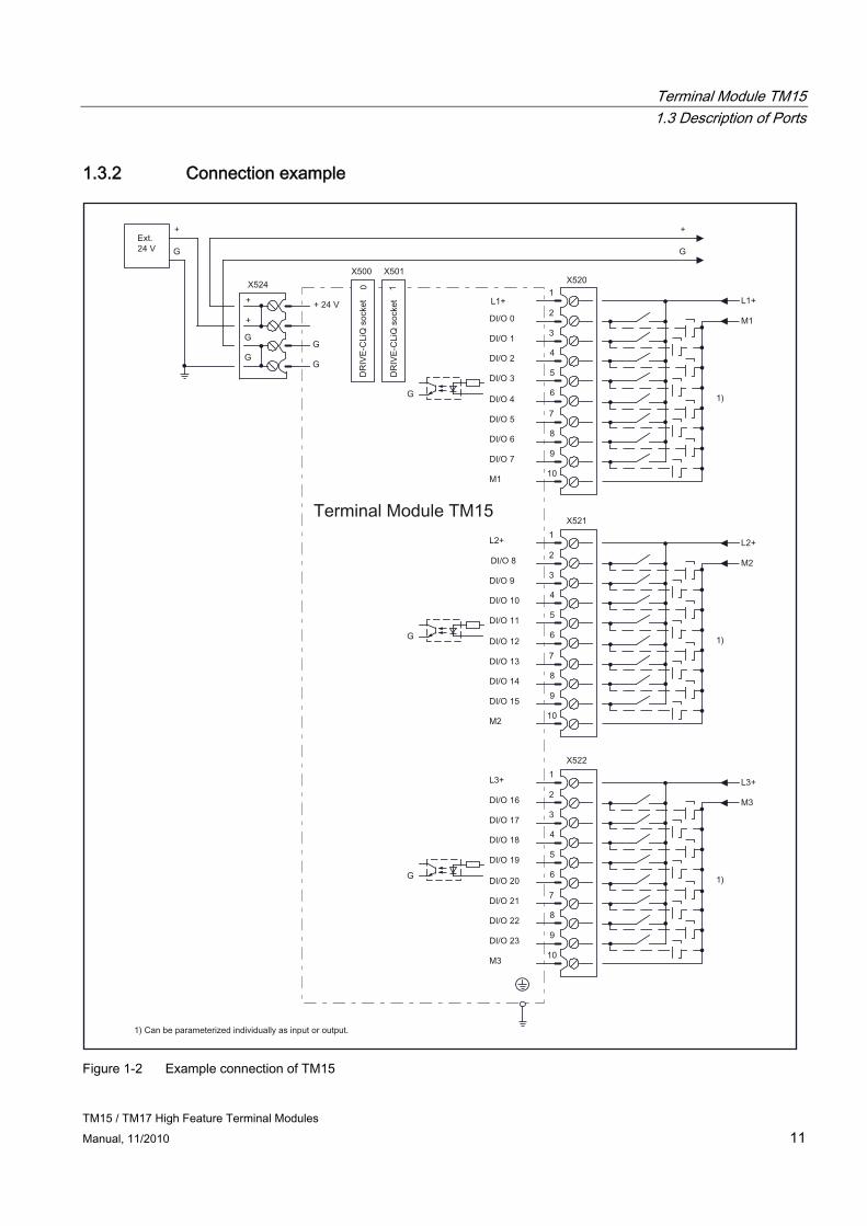
1.3.2 Connection example
Figure 1-2 Example connection of TM15

Terminal Module TM15 1.3 Description of Ports
TM15 / TM17 High Feature Terminal Modules 12 Manual, 11/2010
1.3.3 X500 and X501 DRIVE-CLiQ interface
Table 1- 2 DRIVE-CLiQ interface X500 and X501
Pin Signal name Technical specifications 1 TXP Transmit data + 2 TXN Transmit data - 3 RXP Receive data + 4 Reserved, do not use 5 Reserved, do not use 6 RXN Receive data - 7 Reserved, do not use 8 Reserved, do not use A + (24 V) Power supply
B GND (0 V) Electronic ground Blanking plate for DRIVE-CLiQ interface: Yamaichi, order number: Y-ConAS-13
1.3.4 X524 Electronic power supply
CAUTION It is essential to ensure that the external 24 VDC power supply to the terminal module is not interrupted for longer than 3 ms. After an interruption of 3 ms, the command to reset the component is issued, causing all outputs to be reset.
Table 1- 3 Terminals for the electronic power supply
Terminal Designation Technical specifications + Electronic power supply + Electronic power supply M Electronic ground
M Electronic ground
Voltage: 24 V DC (20.4 V – 28.8 V) Current consumption: max. 0.15 A Max. current via jumper in connector: 20 A at 60 °C
Max. connectable cross-section: 2.5 mm² Type: Screw terminal 2 (see Appendix A)
Terminal Module TM15 1.3 Description of Ports
TM15 / TM17 High Feature Terminal Modules Manual, 11/2010 13
Note
The two "+" and "M" terminals are jumpered in the connector. This ensures that the supply voltage is looped through.
The current consumption increases by the value for the DRIVE-CLiQ node. The digital outputs are supplied via terminals X520, X521, and X522.
Requirements for the power supply Requirements for the power supply are as follows:
Table 1- 4 Requirements for the electronic power supply
Parameter Requirement Current 150 mA1 per module (TM15)
1 Does not include the current provided for the DI/O or for the DRIVE-CLiQ Interface.
The maximum supply current for TM15 is calculated from the sum of the 3 currents below:
● 150 mA, maximum, via X524 connection
(module logic must always be taken into account)
● 450 mA, maximum, via X524
(24 V supply via DRIVE-CLiQ; relevant only if a module connected downcircuit of the TM15 is supplied via DRIVE-CLiQ, e.g. encoder without a separate 24 V connection)
● 24 x 0.5 A, maximum, via X520/X521/X522
(all channels are parameterized as DO and loaded with 0.5 A)
The terminal module monitors the electronic power supply for both overvoltage and undervoltage conditions.
Note
Avoid long cables. The 24 VDC power supply should be located as close as possible to the terminal modules. The total length of all power cables, when added together, must not exceed 10 meters.
Terminal Module TM15 1.3 Description of Ports
TM15 / TM17 High Feature Terminal Modules 14 Manual, 11/2010
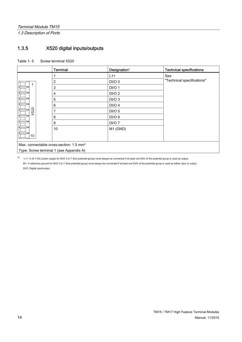
1.3.5 X520 digital inputs/outputs
Table 1- 5 Screw terminal X520
Terminal Designation1 Technical specifications 1 L1+ 2 DI/O 0 3 DI/O 1 4 DI/O 2 5 DI/O 3 6 DI/O 4 7 DI/O 5 8 DI/O 6 9 DI/O 7
10 M1 (GND)
See "Technical specifications"
Max. connectable cross-section: 1.5 mm2 Type: Screw terminal 1 (see Appendix A)
1) L1+: A 24 V DC power supply for DI/O 0 to 7 (first potential group) must always be connected if at least one DI/O of the potential group is used as output.
M1: A reference ground for DI/O 0 to 7 (first potential group) must always be connected if at least one DI/O of the potential group is used as either input or output.
DI/O: Digital input/output
Terminal Module TM15 1.3 Description of Ports
TM15 / TM17 High Feature Terminal Modules Manual, 11/2010 15
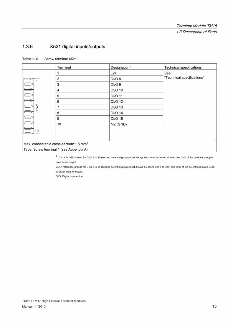
1.3.6 X521 digital inputs/outputs
Table 1- 6 Screw terminal X521
Terminal Designation1 Technical specifications 1 L2+ 2 DI/O 8 3 DI/O 9 4 DI/O 10 5 DI/O 11 6 DI/O 12 7 DI/O 13 8 DI/O 14 9 DI/O 15
10 M2 (GND)
See "Technical specifications"
Max. connectable cross-section: 1.5 mm2 Type: Screw terminal 1 (see Appendix A)
1 L2+: A 24 VDC infeed for DI/O 8 to 15 (second potential group) must always be connected when at least one DI/O of the potential group is
used as an output.
M2: A reference ground for DI/O 8 to 15 (second potential group) must always be connected if at least one DI/O of the potential group is used
as either input or output.
DI/O: Digital input/output
Terminal Module TM15 1.3 Description of Ports
TM15 / TM17 High Feature Terminal Modules 16 Manual, 11/2010
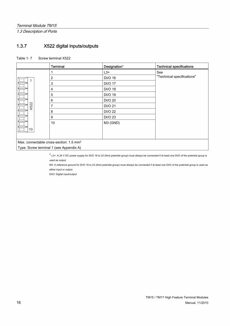
1.3.7 X522 digital inputs/outputs
Table 1- 7 Screw terminal X522
Terminal Designation1 Technical specifications 1 L3+ 2 DI/O 16 3 DI/O 17 4 DI/O 18 5 DI/O 19 6 DI/O 20 7 DI/O 21 8 DI/O 22 9 DI/O 23
10 M3 (GND)
See "Technical specifications"
Max. connectable cross-section: 1.5 mm2 Type: Screw terminal 1 (see Appendix A)
1 L3+: A 24 V DC power supply for DI/O 16 to 23 (third potential group) must always be connected if at least one DI/O of the potential group is
used as output.
M3: A reference ground for DI/O 16 to 23 (third potential group) must always be connected if at least one DI/O of the potential group is used as
either input or output.
DI/O: Digital input/output
Terminal Module TM15 1.3 Description of Ports
TM15 / TM17 High Feature Terminal Modules Manual, 11/2010 17
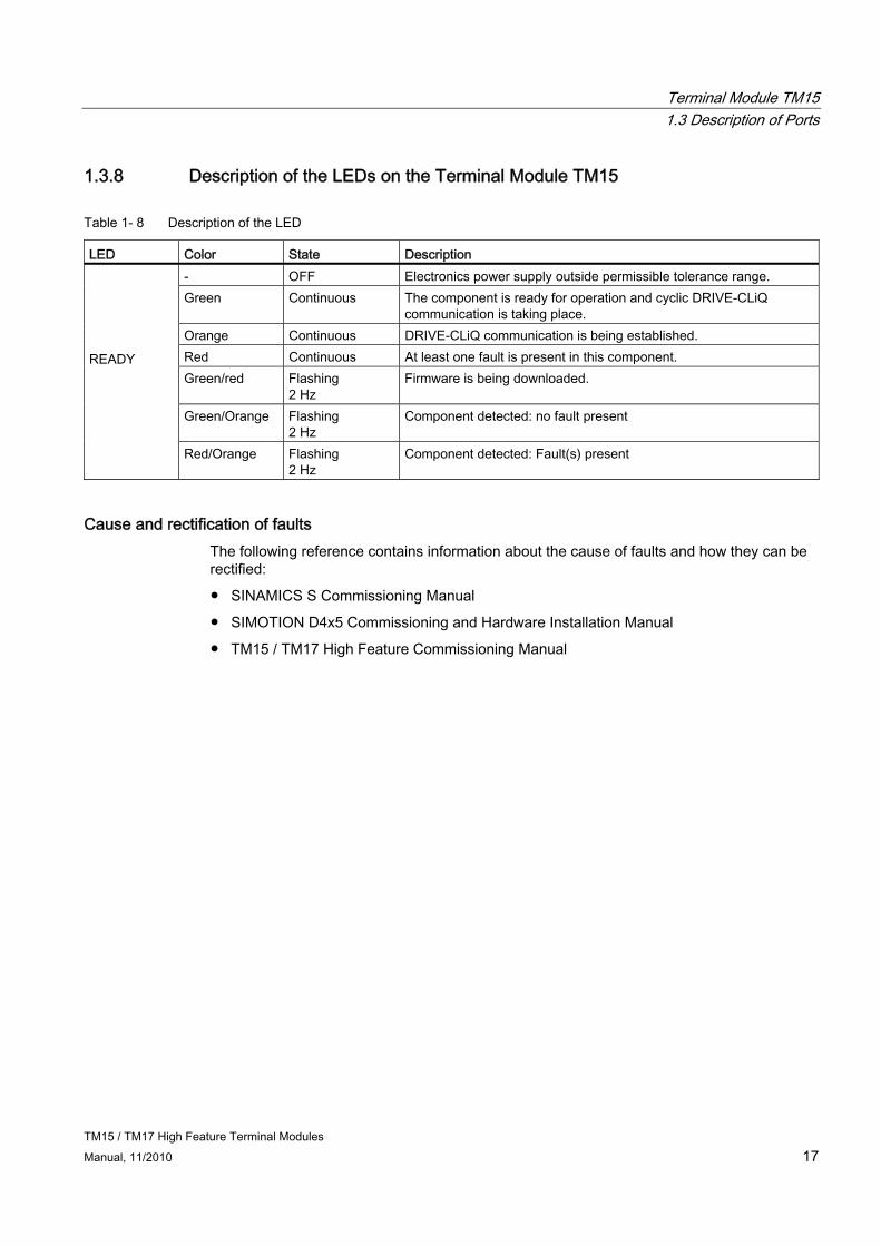
1.3.8 Description of the LEDs on the Terminal Module TM15
Table 1- 8 Description of the LED
LED Color State Description - OFF Electronics power supply outside permissible tolerance range. Green Continuous The component is ready for operation and cyclic DRIVE-CLiQ
communication is taking place. Orange Continuous DRIVE-CLiQ communication is being established. Red Continuous At least one fault is present in this component. Green/red Flashing
2 Hz Firmware is being downloaded.
Green/Orange Flashing 2 Hz
Component detected: no fault present
READY
Red/Orange Flashing 2 Hz
Component detected: Fault(s) present
Cause and rectification of faults The following reference contains information about the cause of faults and how they can be rectified:
● SINAMICS S Commissioning Manual
● SIMOTION D4x5 Commissioning and Hardware Installation Manual
● TM15 / TM17 High Feature Commissioning Manual

Terminal Module TM15 1.4 Dimension Drawing
TM15 / TM17 High Feature Terminal Modules 18 Manual, 11/2010
1.4 Dimension Drawing
Figure 1-3 Dimension drawing of the TM15

Terminal Module TM15 1.5 Installation
TM15 / TM17 High Feature Terminal Modules Manual, 11/2010 19
1.5 Installation
Installation 1. Place the component on the DIN rail.
2. Snap the component on to the DIN rail. Make sure that the mounting slides at the rear latch into place.
3. You can now move the component on the DIN rail to the left or to the right to its final position.
Disassembly
Figure 1-4 Releasing the component from a DIN rail
Terminal Module TM15 1.6 Electrical Connection
TM15 / TM17 High Feature Terminal Modules 20 Manual, 11/2010
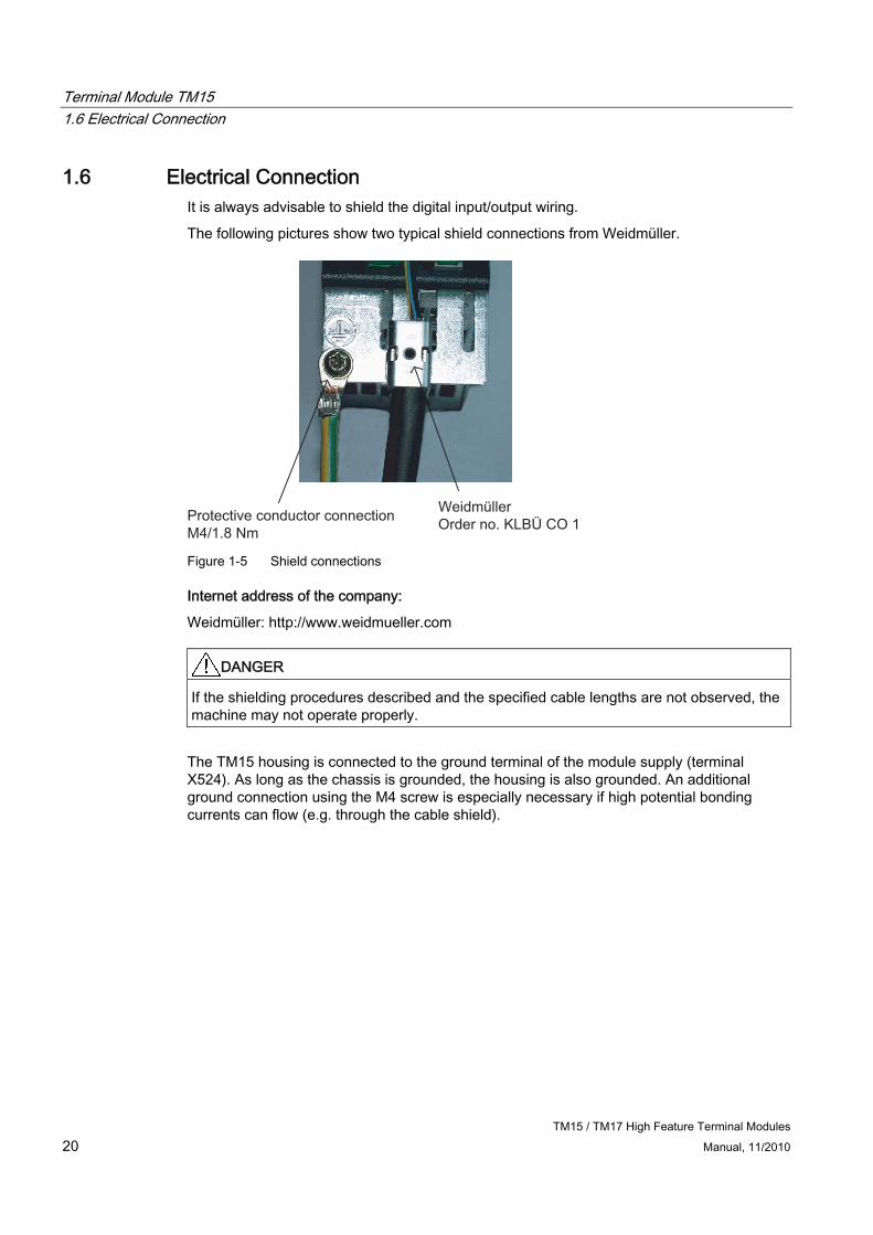
1.6 Electrical Connection It is always advisable to shield the digital input/output wiring.
The following pictures show two typical shield connections from Weidmüller.
WeidmüllerOrder no. KLBÜ CO 1Protective conductor connection
M4/1.8 Nm Figure 1-5 Shield connections
Internet address of the company:
Weidmüller: http://www.weidmueller.com
DANGER If the shielding procedures described and the specified cable lengths are not observed, the machine may not operate properly.
The TM15 housing is connected to the ground terminal of the module supply (terminal X524). As long as the chassis is grounded, the housing is also grounded. An additional ground connection using the M4 screw is especially necessary if high potential bonding currents can flow (e.g. through the cable shield).
Terminal Module TM15 1.6 Electrical Connection
TM15 / TM17 High Feature Terminal Modules Manual, 11/2010 21
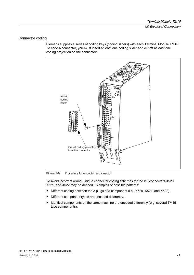
Connector coding Siemens supplies a series of coding keys (coding sliders) with each Terminal Module TM15. To code a connector, you must insert at least one coding slider and cut off at least one coding projection on the connector:
Figure 1-6 Procedure for encoding a connector
To avoid incorrect wiring, unique connector coding schemes for the I/O connectors X520, X521, and X522 may be defined. Examples of possible patterns:
● Different coding between the 3 plugs of a component (i.e., X520, X521, and X522).
● Different component types are encoded differently.
● Identical components on the same machine are encoded differently (e.g. several TM15-type components).
Terminal Module TM15 1.7 Commissioning
TM15 / TM17 High Feature Terminal Modules 22 Manual, 11/2010
1.7 Commissioning
Note
For information about commissioning , see the SIMOTION Terminal Modules TM15 / TM17 High Feature Commissioning Manual.

Terminal Module TM15 1.8 Technical specifications
TM15 / TM17 High Feature Terminal Modules Manual, 11/2010 23
1.8 Technical specifications
Table 1- 9 Technical specifications
Terminal Module TM15 6SL3055-0AA00-3FAx
Unit Value
Electronic power supply Voltage Current (without DRIVE-CLiQ or digital outputs) Power loss
VDC ADC W
24 DC (20.4 – 28.8) 0.15 <3
Ambient temperature up to an altitude of 2000 m °C 0 - 60 Storage temperature °C -40 to +85 Relative humidity 5% to 95%, no condensation I/O
Digital inputs/outputs Each can be parameterized separately as DI or DO
Number of digital inputs/outputs 24
Isolation Yes, in groups of 8
Max. cable length m 30
Digital inputs
Voltage VDC -30 to +30
Low-level (an open digital input is interpreted as "low")
VDC -30 to +5
High level VDC 15 to 30
Input impedance
kΩ 2.8
Current consumption (at 24 V DC) mA 11
Max. voltage in OFF state
VDC 5
Current in OFF state
mA 0.0 to 1.0 (per channel)
Input delay of digital inputs, typical 1) μs For "0" to "1" 50 For "1" to "0" 100
Digital outputs (sustained short-circuit-proof)
Voltage VDC 24
Max. load current per digital output ADC 0.5
Output delay (ohmic load)
typical μs For "0" to "1" 50 For "1" to "0" 150
maximum μs For "0" to "1" 100 For "1" to "0" 225
Terminal Module TM15 1.8 Technical specifications
TM15 / TM17 High Feature Terminal Modules 24 Manual, 11/2010
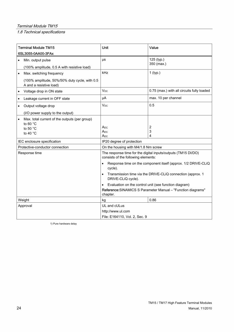
Terminal Module TM15 6SL3055-0AA00-3FAx
Unit Value
Min. output pulse
(100% amplitude, 0.5 A with resistive load)
μs 125 (typ.) 350 (max.)
Max. switching frequency
(100% amplitude, 50%/50% duty cycle, with 0.5 A and a resistive load)
kHz 1 (typ.)
Voltage drop in ON state VDC 0.75 (max.) with all circuits fully loaded
Leakage current in OFF state μA max. 10 per channel
Output voltage drop
(I/O power supply to the output)
VDC 0.5
Max. total current of the outputs (per group) to 60 °C to 50 °C to 40 °C
ADC ADC ADC
2 3 4
IEC enclosure specification IP20 degree of protection Protective-conductor connection On the housing with M4/1.8 Nm screw Response time The response time for the digital inputs/outputs (TM15 DI/DO)
consists of the following elements: Response time on the component itself (approx. 1/2 DRIVE-CLiQ
cycle). Transmission time via the DRIVE-CLiQ connection (approx. 1
DRIVE-CLiQ cycle). Evaluation on the control unit (see function diagram) Reference:SINAMICS S Parameter Manual – "Function diagrams" chapter.
Weight kg 0.86 Approval UL and cULus
http://www.ul.com File: E164110, Vol. 2, Sec. 9
1) Pure hardware delay
TM15 / TM17 High Feature Terminal Modules Manual, 11/2010 25
Terminal Module TM17 High Feature 22.1 Description
The Terminal Module TM17 High Feature is a terminal expansion module for snapping on to a DIN EN 60715 mounting rail. The TM17 High Feature can be used to increase the number of available digital inputs/outputs within a drive system.
Table 2- 1 Interface overview of the TM17 High Feature
Type Quantity Digital inputs/outputs 16 (non-isolated, 2 voltage groups, each with 8 DI/O)
2.2 Safety Information
DANGER The 50 mm clearances above and below the components must be observed.
Terminal Module TM17 High Feature 2.3 Description of Ports
TM15 / TM17 High Feature Terminal Modules 26 Manual, 11/2010
2.3 Description of Ports
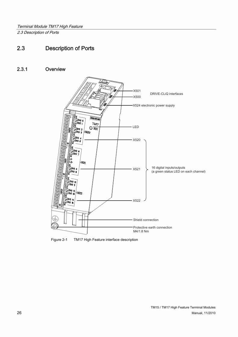
2.3.1 Overview
Figure 2-1 TM17 High Feature interface description

Terminal Module TM17 High Feature 2.3 Description of Ports
TM15 / TM17 High Feature Terminal Modules Manual, 11/2010 27
2.3.2 Sample connection
Figure 2-2 TM17 High Feature connection example
Terminal Module TM17 High Feature 2.3 Description of Ports
TM15 / TM17 High Feature Terminal Modules 28 Manual, 11/2010
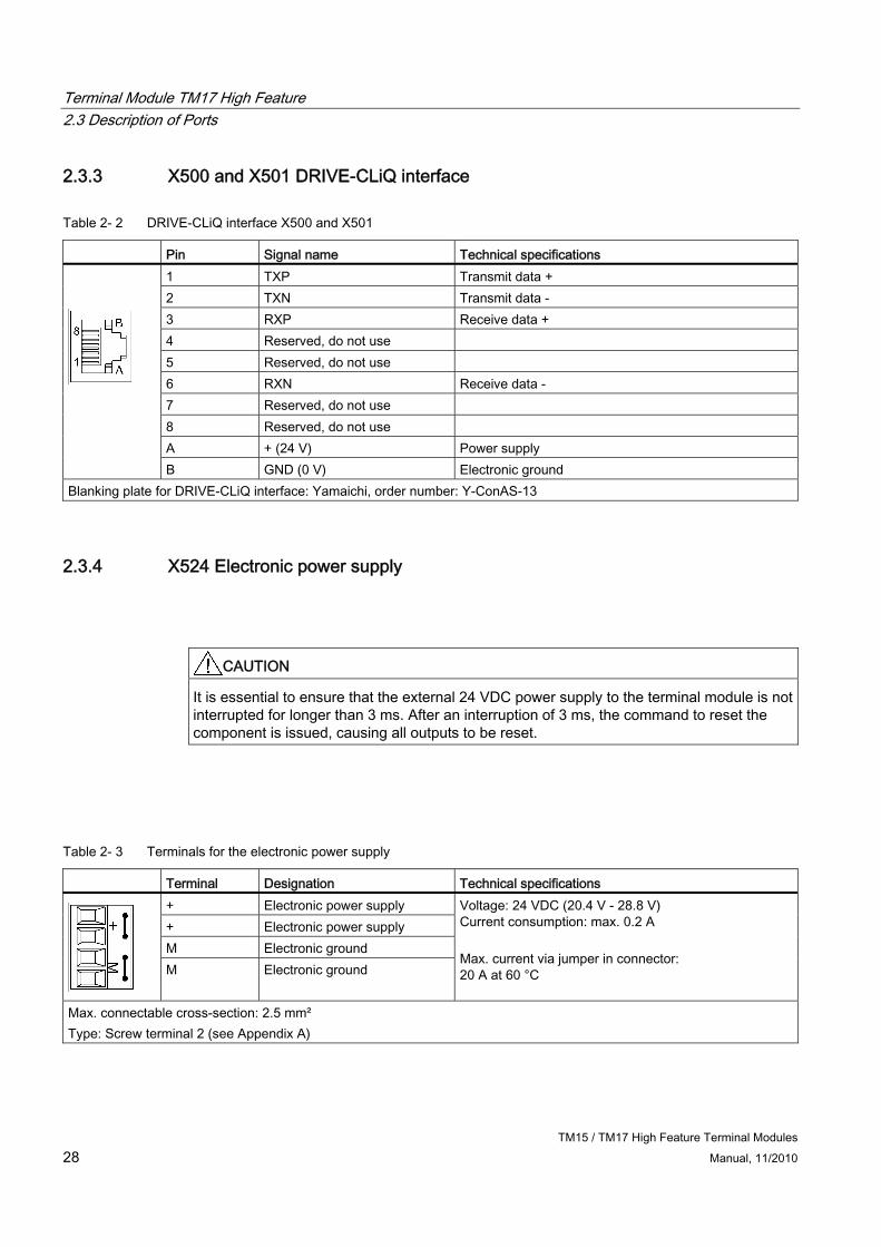
2.3.3 X500 and X501 DRIVE-CLiQ interface
Table 2- 2 DRIVE-CLiQ interface X500 and X501
Pin Signal name Technical specifications 1 TXP Transmit data + 2 TXN Transmit data - 3 RXP Receive data + 4 Reserved, do not use 5 Reserved, do not use 6 RXN Receive data - 7 Reserved, do not use 8 Reserved, do not use A + (24 V) Power supply
B GND (0 V) Electronic ground Blanking plate for DRIVE-CLiQ interface: Yamaichi, order number: Y-ConAS-13
2.3.4 X524 Electronic power supply
CAUTION It is essential to ensure that the external 24 VDC power supply to the terminal module is not interrupted for longer than 3 ms. After an interruption of 3 ms, the command to reset the component is issued, causing all outputs to be reset.
Table 2- 3 Terminals for the electronic power supply
Terminal Designation Technical specifications + Electronic power supply + Electronic power supply M Electronic ground
M Electronic ground
Voltage: 24 VDC (20.4 V - 28.8 V) Current consumption: max. 0.2 A Max. current via jumper in connector: 20 A at 60 °C
Max. connectable cross-section: 2.5 mm² Type: Screw terminal 2 (see Appendix A)

Terminal Module TM17 High Feature 2.3 Description of Ports
TM15 / TM17 High Feature Terminal Modules Manual, 11/2010 29
Note
The two "+" and "M" terminals are jumpered in the connector and not in the device. This ensures that the supply voltage is looped through.
The current consumption increases by the value for the DRIVE-CLiQ node. The digital outputs are supplied via terminals X520, X521, and X522.
Requirements for the power supply Requirements for the power supply are as follows:
Table 2- 4 Requirements for the electronic power supply
Parameter Requirement Current 200 mA1 per module (TM17 High Feature)
1 Does not include the current provided for the DI/O or for the DRIVE-CLiQ Interface.
The maximum supply current for TM17 High Feature is calculated from the sum of the 3 currents below:
● 200 mA, maximum, via X524 connection
(module logic must always be taken into account)
● 450 mA, maximum, via X524
(24 V supply via DRIVE-CLiQ; relevant only if a module connected downcircuit of the TM17 High Feature is supplied via DRIVE-CLiQ, e.g. encoder without a separate 24 V connection)
● 16 x 0.5 A, maximum, via X520/X521/X522
(all channels are parameterized as DO and charged with 0.5 A)
The terminal module monitors the electronic power supply for both overvoltage and undervoltage conditions.
Note
Avoid long cables. The 24 VDC power supply should be located as close as possible to the terminal modules. The total length of all power cables, when added together, must not exceed 10 meters.
Terminal Module TM17 High Feature 2.3 Description of Ports
TM15 / TM17 High Feature Terminal Modules 30 Manual, 11/2010
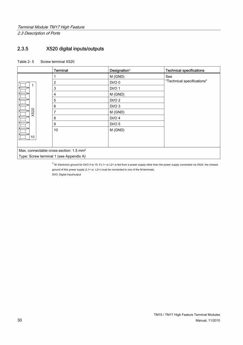
2.3.5 X520 digital inputs/outputs
Table 2- 5 Screw terminal X520
Terminal Designation1 Technical specifications 1 M (GND) 2 DI/O 0 3 DI/O 1 4 M (GND) 5 DI/O 2 6 DI/O 3 7 M (GND) 8 DI/O 4 9 DI/O 5
10 M (GND)
See "Technical specifications"
Max. connectable cross-section: 1.5 mm2 Type: Screw terminal 1 (see Appendix A)
1 M: Electronic ground for DI/O 0 to 15; if L1+ or L2+ is fed from a power supply other than the power supply connected via X524, the chassis
ground of this power supply (L1+ or. L2+) must be connected to one of the M-terminals.
DI/O: Digital input/output
Terminal Module TM17 High Feature 2.3 Description of Ports
TM15 / TM17 High Feature Terminal Modules Manual, 11/2010 31
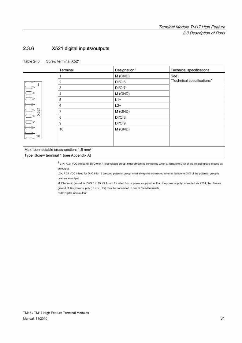
2.3.6 X521 digital inputs/outputs
Table 2- 6 Screw terminal X521
Terminal Designation1 Technical specifications 1 M (GND) 2 DI/O 6 3 DI/O 7 4 M (GND) 5 L1+ 6 L2+ 7 M (GND) 8 DI/O 8 9 DI/O 9
10 M (GND)
See "Technical specifications"
Max. connectable cross-section: 1.5 mm2 Type: Screw terminal 1 (see Appendix A)
1 L1+: A 24 VDC infeed for DI/O 0 to 7 (first voltage group) must always be connected when at least one DI/O of the voltage group is used as
an output.
L2+: A 24 VDC infeed for DI/O 8 to 15 (second potential group) must always be connected when at least one DI/O of the potential group is
used as an output.
M: Electronic ground for DI/O 0 to 15; if L1+ or L2+ is fed from a power supply other than the power supply connected via X524, the chassis
ground of this power supply (L1+ or. L2+) must be connected to one of the M-terminals.
DI/O: Digital input/output
Terminal Module TM17 High Feature 2.3 Description of Ports
TM15 / TM17 High Feature Terminal Modules 32 Manual, 11/2010
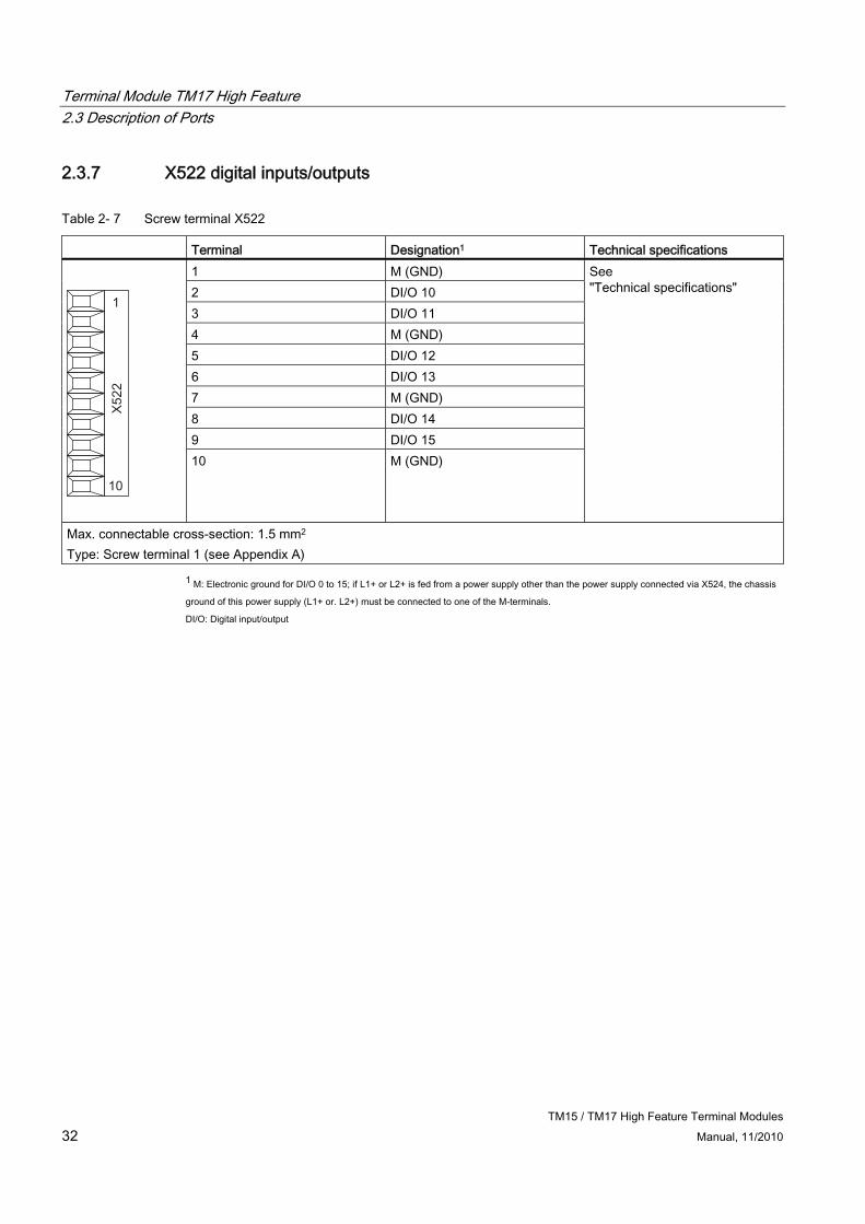
2.3.7 X522 digital inputs/outputs
Table 2- 7 Screw terminal X522
Terminal Designation1 Technical specifications 1 M (GND) 2 DI/O 10 3 DI/O 11 4 M (GND) 5 DI/O 12 6 DI/O 13 7 M (GND) 8 DI/O 14 9 DI/O 15
10 M (GND)
See "Technical specifications"
Max. connectable cross-section: 1.5 mm2 Type: Screw terminal 1 (see Appendix A)
1 M: Electronic ground for DI/O 0 to 15; if L1+ or L2+ is fed from a power supply other than the power supply connected via X524, the chassis
ground of this power supply (L1+ or. L2+) must be connected to one of the M-terminals.
DI/O: Digital input/output
Terminal Module TM17 High Feature 2.3 Description of Ports
TM15 / TM17 High Feature Terminal Modules Manual, 11/2010 33
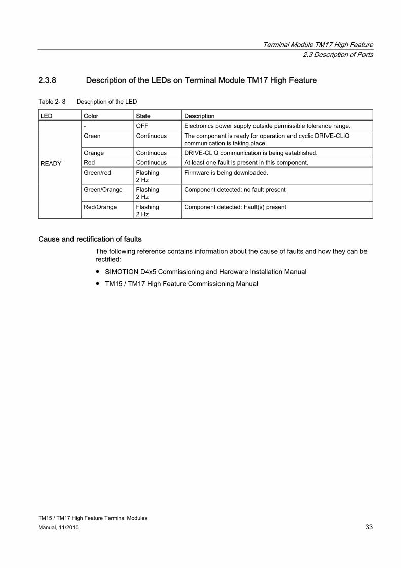
2.3.8 Description of the LEDs on Terminal Module TM17 High Feature
Table 2- 8 Description of the LED
LED Color State Description - OFF Electronics power supply outside permissible tolerance range. Green Continuous The component is ready for operation and cyclic DRIVE-CLiQ
communication is taking place. Orange Continuous DRIVE-CLiQ communication is being established. Red Continuous At least one fault is present in this component. Green/red Flashing
2 Hz Firmware is being downloaded.
Green/Orange Flashing 2 Hz
Component detected: no fault present
READY
Red/Orange Flashing 2 Hz
Component detected: Fault(s) present
Cause and rectification of faults The following reference contains information about the cause of faults and how they can be rectified:
● SIMOTION D4x5 Commissioning and Hardware Installation Manual
● TM15 / TM17 High Feature Commissioning Manual

Terminal Module TM17 High Feature 2.4 Dimension drawing
TM15 / TM17 High Feature Terminal Modules 34 Manual, 11/2010
2.4 Dimension drawing
Figure 2-3 Dimension drawing of TM17 High Feature (like TM15)

Terminal Module TM17 High Feature 2.5 Installation
TM15 / TM17 High Feature Terminal Modules Manual, 11/2010 35
2.5 Installation
Installation 1. Place the component on the DIN rail.
2. Snap the component on to the DIN rail. Make sure that the mounting slides at the rear latch into place.
3. You can now move the component on the DIN rail to the left or to the right to its final position.
Disassembly
Figure 2-4 Releasing the component from a DIN rail
Terminal Module TM17 High Feature 2.6 Electrical Connection
TM15 / TM17 High Feature Terminal Modules 36 Manual, 11/2010
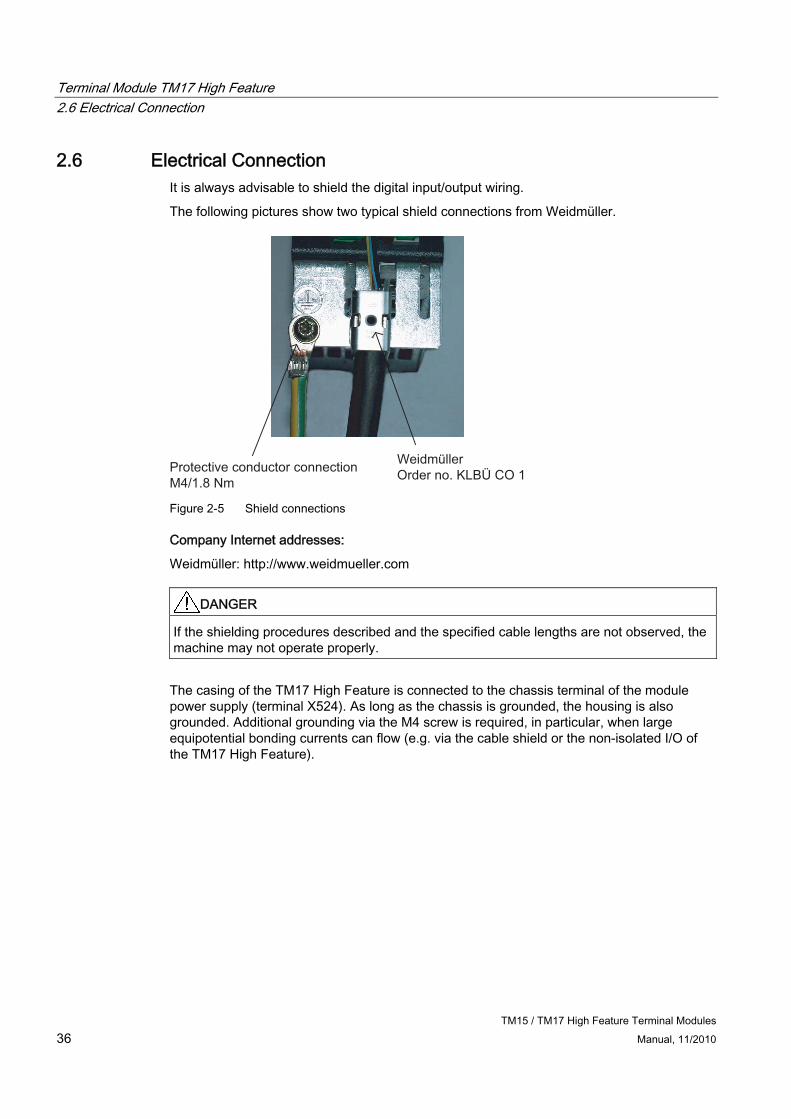
2.6 Electrical Connection It is always advisable to shield the digital input/output wiring.
The following pictures show two typical shield connections from Weidmüller.
WeidmüllerOrder no. KLBÜ CO 1Protective conductor connection
M4/1.8 Nm Figure 2-5 Shield connections
Company Internet addresses:
Weidmüller: http://www.weidmueller.com
DANGER If the shielding procedures described and the specified cable lengths are not observed, the machine may not operate properly.
The casing of the TM17 High Feature is connected to the chassis terminal of the module power supply (terminal X524). As long as the chassis is grounded, the housing is also grounded. Additional grounding via the M4 screw is required, in particular, when large equipotential bonding currents can flow (e.g. via the cable shield or the non-isolated I/O of the TM17 High Feature).

Terminal Module TM17 High Feature 2.6 Electrical Connection
TM15 / TM17 High Feature Terminal Modules Manual, 11/2010 37
Connector coding Siemens supplies a series of coding elements (coding sliders) with each Terminal Module TM17 High Feature. To code a connector, you must insert at least one coding slider and cut off at least one coding projection on the connector:
Figure 2-6 Connector coding - procedure (same as for TM 15)
To avoid incorrect wiring, unique connector coding schemes for the I/O connectors X520, X521, and X522 may be defined. Examples of possible patterns:
● Different coding between the 3 plugs of a component (i.e., X520, X521, and X522).
● Different components are coded differently.
● Identical components on the same machine are coded differently (e.g. several TM17 High Feature components).
Terminal Module TM17 High Feature 2.7 Commissioning
TM15 / TM17 High Feature Terminal Modules 38 Manual, 11/2010
2.7 Commissioning
Note
For information about commissioning , see the SIMOTION Terminal Modules TM15 / TM17 High Feature Commissioning Manual.
Terminal Module TM17 High Feature 2.8 Technical data
TM15 / TM17 High Feature Terminal Modules Manual, 11/2010 39
2.8 Technical data
Table 2- 9 Technical specifications
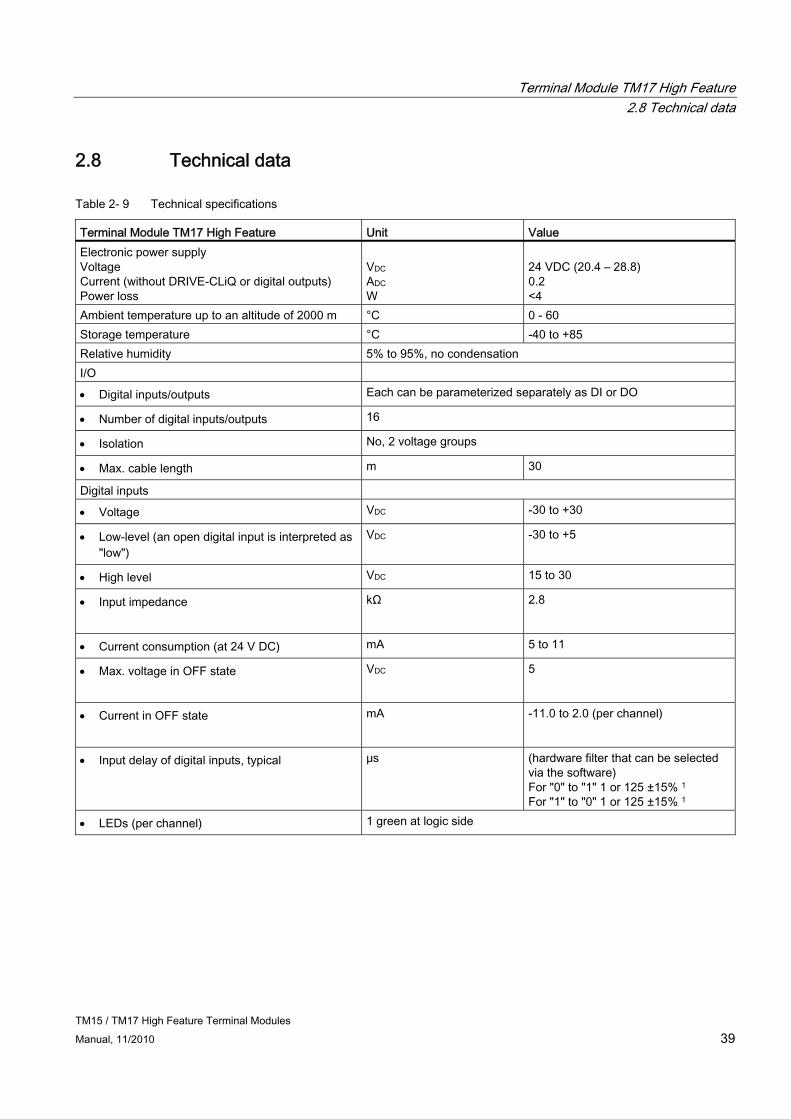
Terminal Module TM17 High Feature Unit Value Electronic power supply Voltage Current (without DRIVE-CLiQ or digital outputs) Power loss
VDC ADC W
24 VDC (20.4 – 28.8) 0.2 <4
Ambient temperature up to an altitude of 2000 m °C 0 - 60 Storage temperature °C -40 to +85 Relative humidity 5% to 95%, no condensation I/O
Digital inputs/outputs Each can be parameterized separately as DI or DO
Number of digital inputs/outputs 16
Isolation No, 2 voltage groups
Max. cable length m 30
Digital inputs
Voltage VDC -30 to +30
Low-level (an open digital input is interpreted as "low")
VDC -30 to +5
High level VDC 15 to 30
Input impedance
kΩ 2.8
Current consumption (at 24 V DC) mA 5 to 11
Max. voltage in OFF state
VDC 5
Current in OFF state
mA -11.0 to 2.0 (per channel)
Input delay of digital inputs, typical μs (hardware filter that can be selected via the software) For "0" to "1" 1 or 125 ±15% 1 For "1" to "0" 1 or 125 ±15% 1
LEDs (per channel) 1 green at logic side
Terminal Module TM17 High Feature 2.8 Technical data
TM15 / TM17 High Feature Terminal Modules 40 Manual, 11/2010
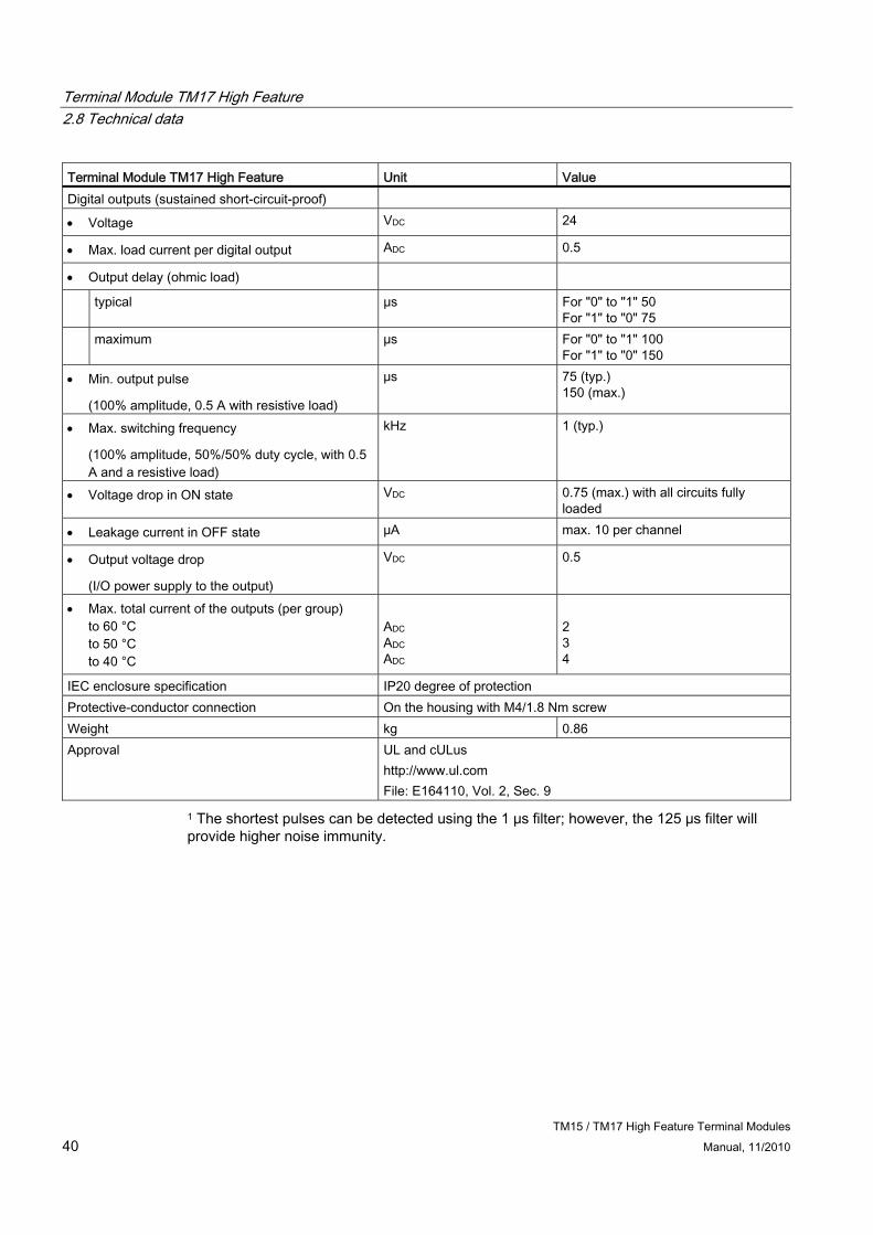
Terminal Module TM17 High Feature Unit Value Digital outputs (sustained short-circuit-proof)
Voltage VDC 24
Max. load current per digital output ADC 0.5
Output delay (ohmic load)
typical μs For "0" to "1" 50 For "1" to "0" 75
maximum μs For "0" to "1" 100 For "1" to "0" 150
Min. output pulse
(100% amplitude, 0.5 A with resistive load)
μs 75 (typ.) 150 (max.)
Max. switching frequency
(100% amplitude, 50%/50% duty cycle, with 0.5 A and a resistive load)
kHz 1 (typ.)
Voltage drop in ON state VDC 0.75 (max.) with all circuits fully loaded
Leakage current in OFF state μA max. 10 per channel
Output voltage drop
(I/O power supply to the output)
VDC 0.5
Max. total current of the outputs (per group) to 60 °C to 50 °C to 40 °C
ADC ADC ADC
2 3 4
IEC enclosure specification IP20 degree of protection Protective-conductor connection On the housing with M4/1.8 Nm screw Weight kg 0.86 Approval UL and cULus
http://www.ul.com File: E164110, Vol. 2, Sec. 9
1 The shortest pulses can be detected using the 1 μs filter; however, the 125 μs filter will provide higher noise immunity.

TM15 / TM17 High Feature Terminal Modules Manual, 11/2010 41
Standards and approvals AA.1 General rules
EN 61131, EN 60950 The SIMOTION programmable controller meets the requirements and criteria of the standards EN 61131 and EN 60950.
CE marking
Our products satisfy the requirements and protection objectives of the EC Directives and comply with the harmonized European standards (EN).
EMC Directive SIMOTION products are designed for industrial use in accordance with product standard DIN EN 61800-3, Category C2.
cULus Approval
Listed component mark for United States and the Canada Underwriters Laboratories (UL) according to Standard UL 508, File E164110, File E115352, File E85972.
EMC USA Federal Communications Commission Radio Frequency Interference Statement
This equipment has been tested and found to comply with the limits for a Class A digital device, pursuant to Part 15 of the FCC Rules. These limits are designed to provide reasonable protection against harmful interference when the equipment is operated in a commercial environment. This equipment generates, uses, and can radiate radio frequency energy and, if not installed and used in accordance with the instruction manual, may cause harmful interference to radio communications. Operation of this equipment in a residential area is likely to cause harmful interference in which case the user will be required to correct the interference at his own expense.
Shielded Cables Shielded cables must be used with this equipment to maintain compliance with FCC regulations.

Standards and approvals A.1 General rules
TM15 / TM17 High Feature Terminal Modules 42 Manual, 11/2010
USA Modifications Changes or modifications not expressly approved by the manufacturer could
void the user’s authority to operate the equipment. Conditions of Operations
This device complies with Part 15 of the FCC Rules. Operation is subject to the following two conditions: (1) this device may not cause harmful interference, and (2) this device must accept any interference received, including interference that may cause undesired operation.
CANADA Canadian Notice This Class B digital apparatus complies with Canadian ICES-003. Avis Canadien Cet appareil numérique de la classe B est conforme à la norme NMB-003 du
Canada.
Declaration of conformity The current Declaration of conformity is available on the Internet at Declaration of conformity (http://support.automation.siemens.com/WW/view/en/10805446/134200).
Electromagnetic compatibility Standards for EMC are satisfied, if the EMC Installation Guideline is observed.
CAUTION There is a risk of injury or of damage to assets. In hazardous areas, personal injury or damage to assets can occur if plug-in connections are disconnected during operation. Always de-energize your equipment in hazardous areas before disconnecting plug-in connections.

Standards and approvals A.2 Safety of electronic controllers
TM15 / TM17 High Feature Terminal Modules Manual, 11/2010 43
A.2 Safety of electronic controllers
Introduction The following remarks relate to fundamental criteria and apply irrespective of the type of controller and the manufacturer.
Risk A higher degree of safety standard applies to all applications and situations where there is a risk of material damage or injury to persons if there is a failure. Special regulations specific to the system apply to such applications. These must be taken into account for configuration of the controller (e.g. VDE 0116 for furnaces).
For electronic controllers with safety responsibility, the measures required for preventing or controlling faults depend on the hazard inherent in the plant. In this respect, the basic measures listed above are no longer adequate once the hazard exceeds a certain potential. Additional measures (e.g. double redundancy, tests, checksums, etc.) for the controller must implemented and certified (DIN VDE 0801).
The residual risk When assessing his machine's risk in accordance with the EC Machinery Directive, the machine manufacturer must take into account the following residual risks emanating from the control and drive components:
1. Unintentional movements of driven machine components during commissioning, operation, maintenance, and repairs caused by, for example:
– Hardware defects and/or software errors in the sensors, controllers, actuators, and connection technology
– Response times of the controller and drive
– Operating and/or ambient conditions not within the scope of the specification
– Parameterization, programming, cabling, and installation errors
– Use of radio devices / cellular phones in the immediate vicinity of the controller
– External influences / damage
2. Exceptional temperatures as well as emissions of light, noise, particles, or gas caused by, for example:
– Component malfunctions
– Software errors
– Operating and/or ambient conditions not within the scope of the specification
– External influences / damage
Standards and approvals A.2 Safety of electronic controllers
TM15 / TM17 High Feature Terminal Modules 44 Manual, 11/2010
3. Hazardous shock voltages caused by, for example:
– Component malfunctions
– Influence of electrostatic charging
– Induction of voltages in moving motors
– Operating and/or ambient conditions not within the scope of the specification
– Condensation / conductive contamination
– External influences / damage
4. Electrical, magnetic and electromagnetic fields generated in operation that can pose a risk to people with a pacemaker, implants or metal replacement joints, etc. if they are too close
5. Release of environmental pollutants or emissions as a result of improper operation of the system and/or failure to dispose of components safely and correctly

TM15 / TM17 High Feature Terminal Modules Manual, 11/2010 45
ESD guidelines BB.1 ESD definition
What does ESD mean? All electronic modules are equipped with highly integrated modules or components. Because of the technology used, these electronic components are very sensitive to overvoltages and thus to discharge of static electricity.
The acronym ESD has become the established designation for such Electrostatic Sensitive Devices. The ESD designation is used internationally to refer to electrostatic sensitive devices.
Electrostatic sensitive devices are identified by the following symbol:
Figure B-1 Symbol for identification of electrostatic sensitive devices
CAUTION Electrostatic sensitive devices can be irreparably damaged by voltages that are far lower than anything a person can perceive. These voltages occur if you touch a component or the electrical connection of a module without having previously discharged any static from your body. Any damage that occurs to a module as a result of overvoltage is generally not recognized immediately and only comes to light after the equipment has been operating for some time.
ESD guidelines B.2 Electrostatic accumulation on individuals
TM15 / TM17 High Feature Terminal Modules 46 Manual, 11/2010
B.2 Electrostatic accumulation on individuals
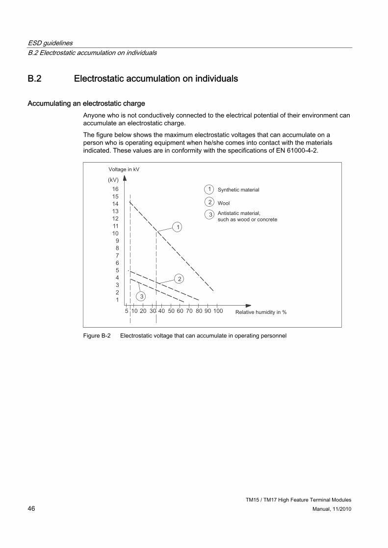
Accumulating an electrostatic charge Anyone who is not conductively connected to the electrical potential of their environment can accumulate an electrostatic charge.
The figure below shows the maximum electrostatic voltages that can accumulate on a person who is operating equipment when he/she comes into contact with the materials indicated. These values are in conformity with the specifications of EN 61000-4-2.
Figure B-2 Electrostatic voltage that can accumulate in operating personnel
ESD guidelines B.3 Basic measures for protection against discharge of static electricity
TM15 / TM17 High Feature Terminal Modules Manual, 11/2010 47
B.3 Basic measures for protection against discharge of static electricity
Make sure the grounding is good When working with electrostatically sensitive devices, make sure that the person, the workstation and the packaging are properly grounded. This is how you can avoid the accumulation of static electricity.
Avoid direct contact Never touch electrostatically sensitive devices if this can be avoided (for example, during maintenance work). When you touch modules, make sure that you do not touch either the pins on the modules or the printed conductors. If you follow these instructions, electrostatic discharge cannot reach or damage sensitive components.
If you have to take measurements on a module, make sure that you first discharge any static that may have accumulated in your body. To do this, touch a grounded metal object. Only use grounded measuring instruments.

ESD guidelines B.3 Basic measures for protection against discharge of static electricity
TM15 / TM17 High Feature Terminal Modules 48 Manual, 11/2010
TM15 / TM17 High Feature Terminal Modules Manual, 11/2010 49
Index
C CE marking, 41 Components
Terminal Module TM15, 9 Terminal Module TM17 High Feature, 25
cULus Approval, 41 Current in OFF state - input, 23, 39
D Declaration of conformity, 42 Dimension drawings
Terminal Module TM15, 18 DRIVE-CLiQ
General, 13, 28, 29
E Electrical connections
Terminal Module 17 High Feature (TM17 High Feature), 36 Terminal Module TM15, 20
Electromagnetic compatibility, 42 EMC guidelines, 41 EN 60950, 41 EN 61131, 41 Enclosure specification, 24, 40 ESD guideline, 45
G Guideline
ESD, 45
H Humidity, 23, 39
I IEC enclosure specification, 24, 40 Impedance - Input, 23, 39
Input specification Impedance, 23, 39 Max. voltage in OFF state, 23, 39 Off-state current range, 23, 39
Interface descriptions Terminal Module TM15, 10
L Length of cable
Voltage supply, 13, 29
M Max. off-state voltage - Input, 23, 39 Max. switching frequency - output, 24, 40 Min. output pulse, 24, 40
O Output, technical specification
Leakage current in OFF state, 24, 40 Max. switching frequency, 24, 40 Min. output pulse, 24, 40 Voltage drop, 24, 40 Voltage drop in ON state, 24, 40
R References, 4 Relative humidity, 23, 39 Reliability
Risk, 43 Residual risk, 43
S Safety of electronic controllers, 43 Storage temperature, 23, 39
T Technical specifications
Terminal Module TM15, 23
Index
TM15 / TM17 High Feature Terminal Modules 50 Manual, 11/2010
Terminal Module TM17 High Feature (TM17 High Feature), 39
Temperature range Storage,
Terminal Module 17 High Feature (TM17 High Feature), 36 Terminal Module TM15, 9
U UL certification, 41
V Voltage drop - output, 24, 40 Voltage drop in the ON state - output, 24, 40 Voltage supply
Length of cable,