Embed Size (px)
Citation preview
Montezuma Properties, LLC
Montezuma Properties, LLC
07/07/2017
M
STATE OF INDIANA
NOT TO SCALE
SITE LOCATION
TERRE HAUTE
VIGO COUNTY
INDIANA
VICINITY OF TERRE HAUTE, INDIANA
NOT TO SCALE
PROJECT LOCATION
Existing Linework Existing Linework Design Linework
LOCATION MAP
Release DateDesignationSheet Number
INDEX OF SHEETS
LOCATION MAP
LEGEND
Boundary Monuments Utility Topo Misc Topo
C1.0
C2.0
C3.0
C4.0
C5.0
C6.0
C7.0
C8.0
C9.0
C10.0
C11.0
C12.0
Cover Sheet
Existing Conditions / Demolition Plan
Site Plan
Grading Plan
Utility Plan
Stormwater Pollution Prevention Plan
Erosion Control Plan
Erosion Control Details
General Details 1
General Details 2
General Details 3
Specifications Sheet
1950 Springhill Drive
Sec. 11, Township 11 North, Range 9 West
Terre Haute, Vigo County, Indiana
HWS
MJV
JDM
Montezuma
Properties, LLC
1950 Springhill Drive
SCALE:
APPROVED BY:
CHECKED BY:
DRAWN BY:
DRAWING NAME:
FILE NAME:
PROJECT NUMBER:
RECORD OWNER:CLIENT:
DATE NO. REVISIONS BY CHECKED
TM17-169_Civils.DWG
TM17-169
07/07/2017
DO NOT SCALE PRINT
DATE:
Montezuma
Properties, LLC
NACover Sheet
SHEET C1.0
07/07/2017
07/07/2017
07/07/2017
07/07/2017
07/07/2017
07/07/2017
07/07/2017
07/07/2017
07/07/2017
07/07/2017
07/07/2017
Revised 7/28/17
Revised 7/28/17
Revised 7/28/17
Revised 7/28/17
7/28/17 1 Revise sheets 1, 3, 5, 11 MV
; Revised 8/02/17
; Revised 8/02/17
8/02/17 2 Revise sheet 3 MV
8/10/17 3 Revise sheet 5.0 MV
; Revised 8/10/17
; Revised 8/10/17
R:\TM
2017\TM
17-169 1950 E. Sp
rin
gh
ill - M
on
tezu
ma P
ro
p LLC
\C
ivils\TM
17-169_C
ivils.d
wg
, 9/12/2017 12:49:42 P
M, 1:1
East S p r i n g h i l l Drive
E
r
i
e
C
a
n
a
l
R
o
a
d
Existing Conditions / Demolition Plan
MY
ERS
ENGINEER ING , INC
.
TERRE HAUTE , I N
Existing Conditions
1"=20'Existing Conditions
SHEET C2.0
DATE:
1950 Springhill Drive
Sec. 11, Township 11 North, Range 9 West
Terre Haute, Vigo County, Indiana
HWS
MJV
JDM
Montezuma
Properties, LLC
1950 Springhill Drive
SCALE:
APPROVED BY:
CHECKED BY:
DRAWN BY:
DRAWING NAME:
FILE NAME:
PROJECT NUMBER:
RECORD OWNER:CLIENT:
DATE NO. REVISIONS BY CHECKED
TM17-169_Civils.DWG
TM17-169
07/07/2017
DO NOT SCALE PRINT
DATE:
Montezuma
Properties, LLC
GENERAL NOTES:
1. UNLESS OTHERWISE NOTED, REMOVE TREES,
SHRUBS AND STUMPS TO WITHIN THE PROPERTY
LINES.
2. POSSIBLE OLD SEPTIC TANKS AND FIELDS MAY
EXIST, IF ENCOUNTERED THEY ARE TO BE
REMOVED IN ACCORDANCE WITH INDIANA
DEPARTMENT OF HEALTH SPECIFICATIONS.
3. UNLESS OTHERWISE NOTED, ALL EXISTING
STRUCTURES AND PAVEMENT LOCATED ON SITE
SHALL BE REMOVED.
R:\TM
2017\TM
17-169 1950 E. Sp
rin
gh
ill - M
on
tezu
ma P
ro
p LLC
\C
ivils\TM
17-169_C
ivils.d
wg
, 9/12/2017 12:49:53 P
M, 1:1
S S
S
S
S S S
S
S
Site Plan
MY
ERS
ENGINEER ING , INC
.
TERRE HAUTE , I N
Site Plan
1"=20' Site Plan
SHEET C3.0
1950 Springhill Drive
Sec. 11, Township 11 North, Range 9 West
Terre Haute, Vigo County, Indiana
HWS
MJV
JDM
Montezuma
Properties, LLC
1950 Springhill Drive
SCALE:
APPROVED BY:
CHECKED BY:
DRAWN BY:
DRAWING NAME:
FILE NAME:
PROJECT NUMBER:
RECORD OWNER:CLIENT:
DATE NO. REVISIONS BY CHECKED
TM17-169_Civils.DWG
TM17-169
07/07/2017
DO NOT SCALE PRINT
DATE:
Montezuma
Properties, LLC
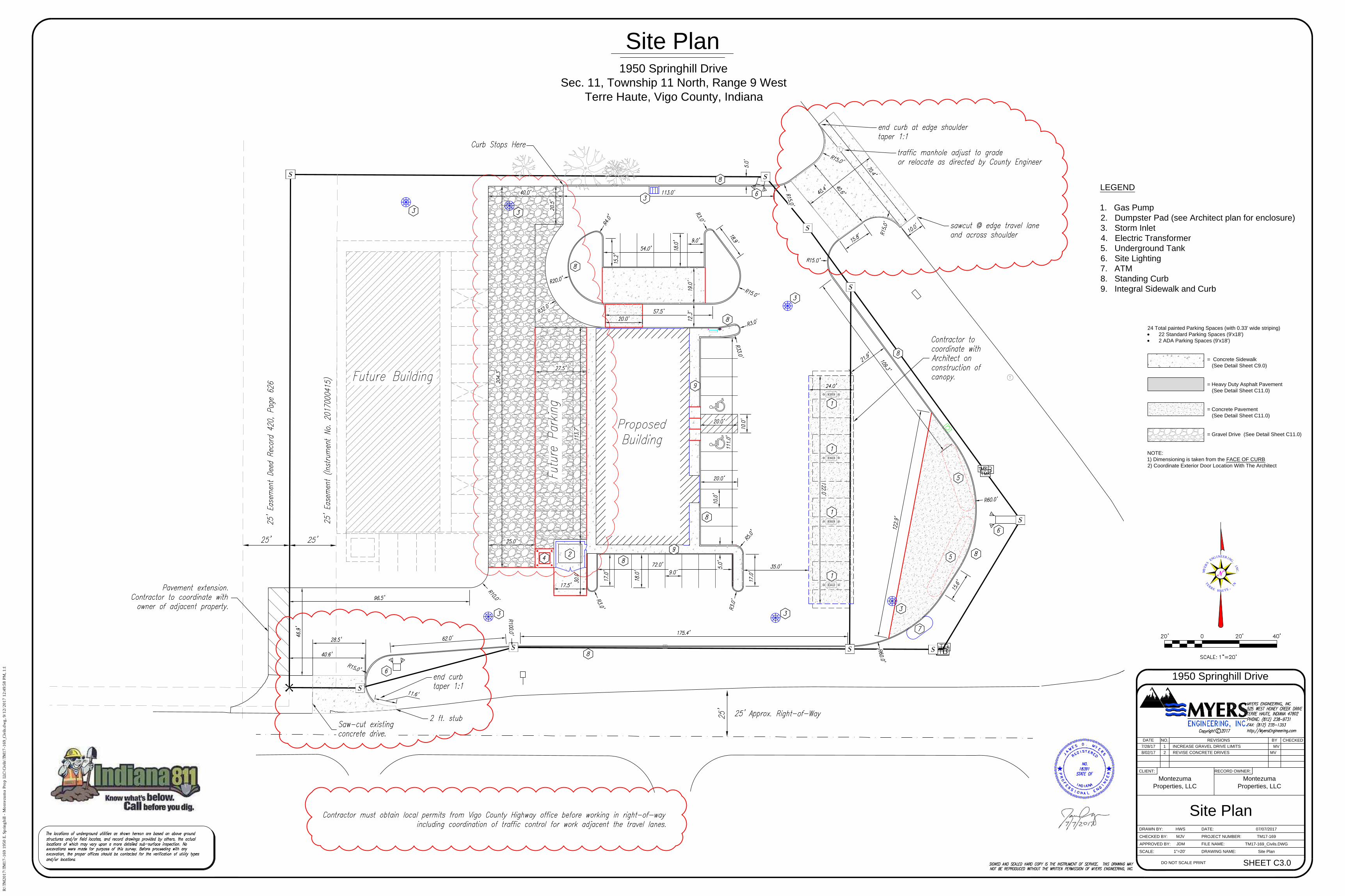
24 Total painted Parking Spaces (with 0.33' wide striping)
· 22 Standard Parking Spaces (9'x18')
· 2 ADA Parking Spaces (9'x18')
= Concrete Sidewalk
(See Detail Sheet C9.0)
= Heavy Duty Asphalt Pavement
(See Detail Sheet C11.0)
= Concrete Pavement
(See Detail Sheet C11.0)
= Gravel Drive (See Detail Sheet C11.0)
NOTE:
1) Dimensioning is taken from the FACE OF CURB
2) Coordinate Exterior Door Location With The Architect
LEGEND
1. Gas Pump
2. Dumpster Pad (see Architect plan for enclosure)
3. Storm Inlet
4. Electric Transformer
5. Underground Tank
6. Site Lighting
7. ATM
8. Standing Curb
9. Integral Sidewalk and Curb
7/28/17 1 INCREASE GRAVEL DRIVE LIMITS MV
8/02/17 2 REVISE CONCRETE DRIVES MV
R:\TM
2017\TM
17-169 1950 E. Sp
rin
gh
ill - M
on
tezu
ma P
ro
p LLC
\C
ivils\TM
17-169_C
ivils.d
wg
, 9/12/2017 12:49:58 P
M, 1:1
H.P.
H.P.
H.P.
H.P.
Grading Plan
MY
ERS
ENGINEER ING , INC
.
TERRE HAUTE , I N
Grading Plan
1"=XX' Grading Plan
SHEET C4.0
1950 Springhill Drive
Sec. 11, Township 11 North, Range 9 West
Terre Haute, Vigo County, Indiana
HWS
MJV
JDM
Montezuma
Properties, LLC
1950 Springhill Drive
SCALE:
APPROVED BY:
CHECKED BY:
DRAWN BY:
DRAWING NAME:
FILE NAME:
PROJECT NUMBER:
RECORD OWNER:CLIENT:
DATE NO. REVISIONS BY CHECKED
TM17-169_Civils.DWG
TM17-169
07/07/2017
DO NOT SCALE PRINT
DATE:
Montezuma
Properties, LLC
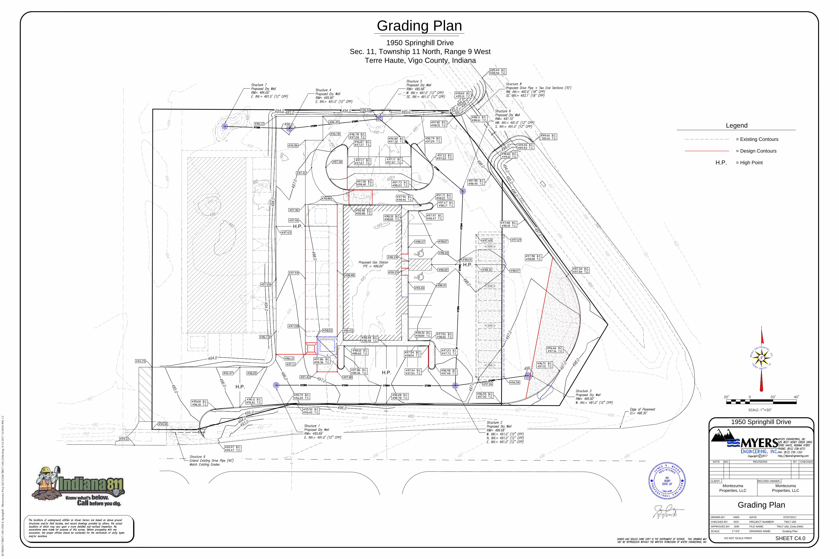
Legend
= Existing Contours
= Design Contours
= High PointH.P.
R:\TM
2017\TM
17-169 1950 E. Sp
rin
gh
ill - M
on
tezu
ma P
ro
p LLC
\C
ivils\TM
17-169_C
ivils.d
wg
, 9/12/2017 12:50:03 P
M, 1:1
U
N
D
E
R
G
R
O
U
N
D
T
A
N
K
A
T
M
U
N
D
E
R
G
R
O
U
N
D
T
A
N
K
East S p r i n g h i l l Drive
Utility Plan
MY
ERS
ENGINEER ING , INC
.
TERRE HAUTE , I N
Utility Plan
1"=XX' Utility Plan
SHEET C5.0
1950 Springhill Drive
Sec. 11, Township 11 North, Range 9 West
Terre Haute, Vigo County, Indiana
HWS
MJV
JDM
Montezuma
Properties, LLC
1950 Springhill Drive
SCALE:
APPROVED BY:
CHECKED BY:
DRAWN BY:
DRAWING NAME:
FILE NAME:
PROJECT NUMBER:
RECORD OWNER:CLIENT:
DATE NO. REVISIONS BY CHECKED
TM17-169_Civils.DWG
TM17-169
07/07/2017
DO NOT SCALE PRINT
DATE:
Montezuma
Properties, LLC
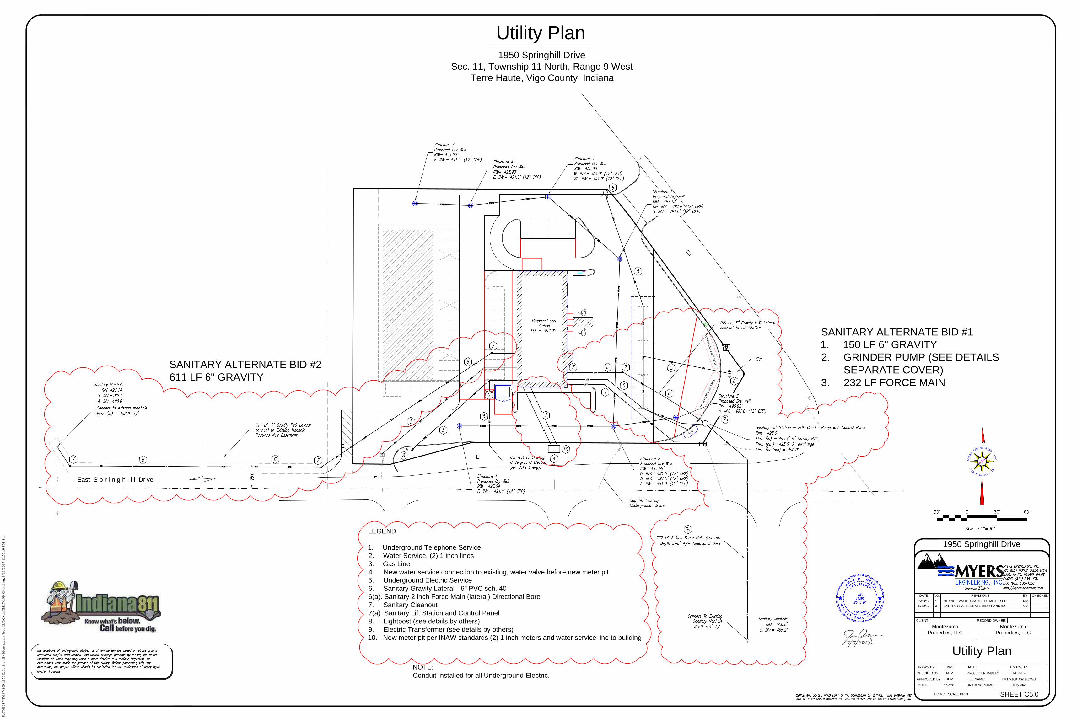
LEGEND
1. Underground Telephone Service
2. Water Service, (2) 1 inch lines
3. Gas Line
4. New water service connection to existing, water valve before new meter pit.
5. Underground Electric Service
6. Sanitary Gravity Lateral - 6" PVC sch. 40
6(a). Sanitary 2 inch Force Main (lateral) Directional Bore
7. Sanitary Cleanout
7(a) Sanitary Lift Station and Control Panel
8. Lightpost (see details by others)
9. Electric Transformer (see details by others)
10. New meter pit per INAW standards (2) 1 inch meters and water service line to building
NOTE:
Conduit Installed for all Underground Electric.
7/28/17 1 CHANGE WATER VAULT TO METER PIT MV
8/10/17 3 SANITARY ALTERNATE BID #1 AND #2 MV
SANITARY ALTERNATE BID #1
1. 150 LF 6" GRAVITY
2. GRINDER PUMP (SEE DETAILS
SEPARATE COVER)
3. 232 LF FORCE MAIN
SANITARY ALTERNATE BID #2
611 LF 6" GRAVITY
R:\TM
2017\TM
17-169 1950 E. Sp
rin
gh
ill - M
on
tezu
ma P
ro
p LLC
\C
ivils\TM
17-169_C
ivils.d
wg
, 9/12/2017 12:50:18 P
M, 1:1
Stormwater Pollution
Prevention Plan
N/A SWPPP
SHEET C6.0
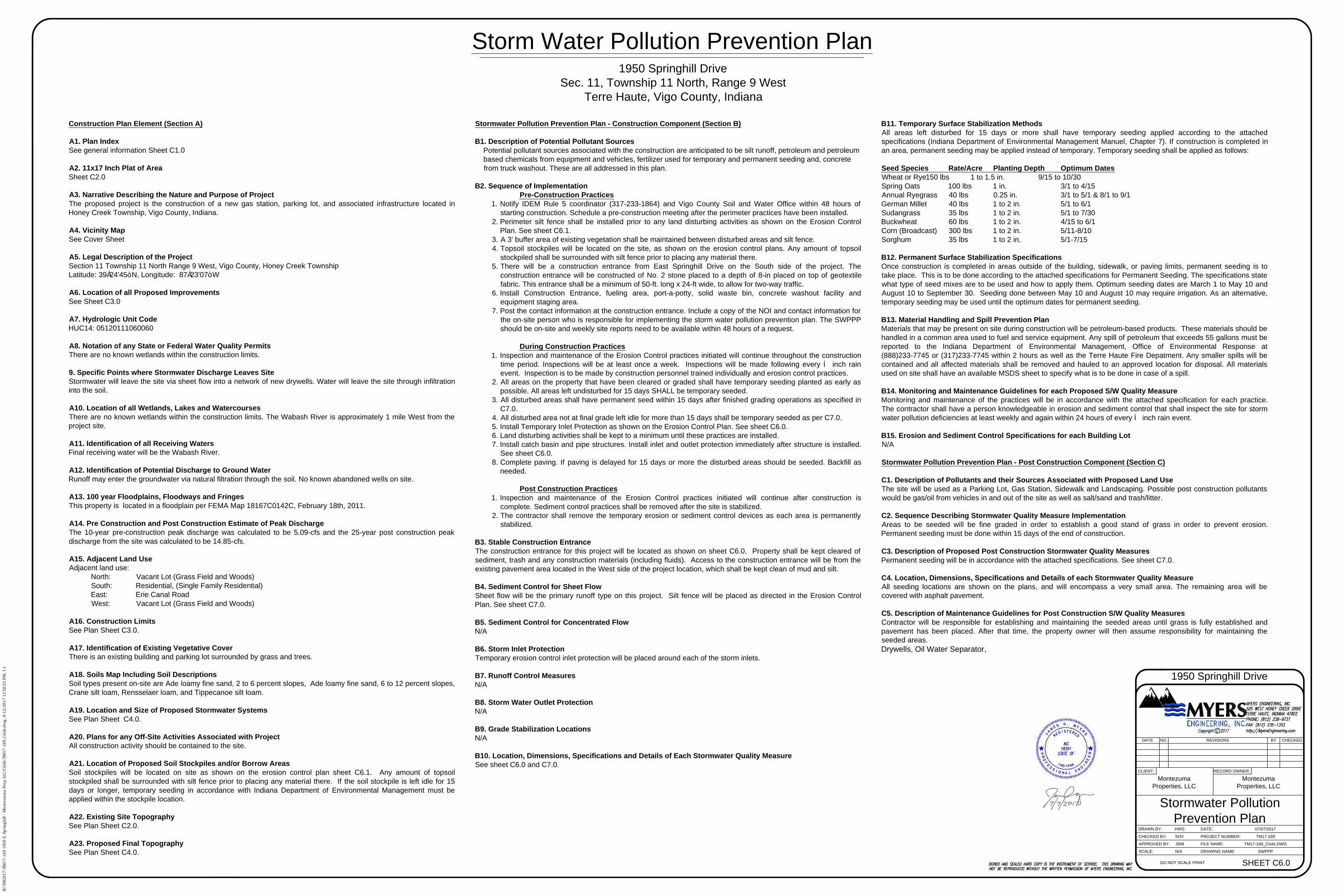
Construction Plan Element (Section A)
A1. Plan Index
See general information Sheet C1.0
A2. 11x17 Inch Plat of Area
Sheet C2.0
A3. Narrative Describing the Nature and Purpose of Project
The proposed project is the construction of a new gas station, parking lot, and associated infrastructure located in
Honey Creek Township, Vigo County, Indiana.
A4. Vicinity Map
See Cover Sheet
A5. Legal Description of the Project
Section 11 Township 11 North Range 9 West, Vigo County, Honey Creek Township
Latitude: 39°24'45” N, Longitude: 87°23'07” W
A6. Location of all Proposed Improvements
See Sheet C3.0
A7. Hydrologic Unit Code
HUC14: 05120111060060
A8. Notation of any State or Federal Water Quality Permits
There are no known wetlands within the construction limits.
9. Specific Points where Stormwater Discharge Leaves Site
Stormwater will leave the site via sheet flow into a network of new drywells. Water will leave the site through infiltration
into the soil.
A10. Location of all Wetlands, Lakes and Watercourses
There are no known wetlands within the construction limits. The Wabash River is approximately 1 mile West from the
project site.
A11. Identification of all Receiving Waters
Final receiving water will be the Wabash River.
A12. Identification of Potential Discharge to Ground Water
Runoff may enter the groundwater via natural filtration through the soil. No known abandoned wells on site.
A13. 100 year Floodplains, Floodways and Fringes
This property is located in a floodplain per FEMA Map 18167C0142C, February 18th, 2011.
A14. Pre Construction and Post Construction Estimate of Peak Discharge
The 10-year pre-construction peak discharge was calculated to be 5.09-cfs and the 25-year post construction peak
discharge from the site was calculated to be 14.85-cfs.
A15. Adjacent Land Use
Adjacent land use:
North: Vacant Lot (Grass Field and Woods)
South: Residential, (Single Family Residential)
East: Erie Canal Road
West: Vacant Lot (Grass Field and Woods)
A16. Construction Limits
See Plan Sheet C3.0.
A17. Identification of Existing Vegetative Cover
There is an existing building and parking lot surrounded by grass and trees.
A18. Soils Map Including Soil Descriptions
Soil types present on-site are Ade loamy fine sand, 2 to 6 percent slopes, Ade loamy fine sand, 6 to 12 percent slopes,
Crane silt loam, Rensselaer loam, and Tippecanoe silt loam.
A19. Location and Size of Proposed Stormwater Systems
See Plan Sheet C4.0.
A20. Plans for any Off-Site Activities Associated with Project
All construction activity should be contained to the site.
A21. Location of Proposed Soil Stockpiles and/or Borrow Areas
Soil stockpiles will be located on site as shown on the erosion control plan sheet C6.1. Any amount of topsoil
stockpiled shall be surrounded with silt fence prior to placing any material there. If the soil stockpile is left idle for 15
days or longer, temporary seeding in accordance with Indiana Department of Environmental Management must be
applied within the stockpile location.
A22. Existing Site Topography
See Plan Sheet C2.0.
A23. Proposed Final Topography
See Plan Sheet C4.0.
Stormwater Pollution Prevention Plan - Construction Component (Section B)
B1. Description of Potential Pollutant Sources
Potential pollutant sources associated with the construction are anticipated to be silt runoff, petroleum and petroleum
based chemicals from equipment and vehicles, fertilizer used for temporary and permanent seeding and, concrete
from truck washout. These are all addressed in this plan.
B2. Sequence of Implementation
Pre-Construction Practices
1. Notify IDEM Rule 5 coordinator (317-233-1864) and Vigo County Soil and Water Office within 48 hours of
starting construction. Schedule a pre-construction meeting after the perimeter practices have been installed.
2. Perimeter silt fence shall be installed prior to any land disturbing activities as shown on the Erosion Control
Plan. See sheet C6.1.
3. A 3' buffer area of existing vegetation shall be maintained between disturbed areas and silt fence.
4. Topsoil stockpiles will be located on the site, as shown on the erosion control plans. Any amount of topsoil
stockpiled shall be surrounded with silt fence prior to placing any material there.
5. There will be a construction entrance from East Springhill Drive on the South side of the project. The
construction entrance will be constructed of No. 2 stone placed to a depth of 8-in placed on top of geotextile
fabric. This entrance shall be a minimum of 50-ft. long x 24-ft wide, to allow for two-way traffic.
6. Install Construction Entrance, fueling area, port-a-potty, solid waste bin, concrete washout facility and
equipment staging area.
7. Post the contact information at the construction entrance. Include a copy of the NOI and contact information for
the on-site person who is responsible for implementing the storm water pollution prevention plan. The SWPPP
should be on-site and weekly site reports need to be available within 48 hours of a request.
During Construction Practices
1. Inspection and maintenance of the Erosion Control practices initiated will continue throughout the construction
time period. Inspections will be at least once a week. Inspections will be made following every ½ inch rain
event. Inspection is to be made by construction personnel trained individually and erosion control practices.
2. All areas on the property that have been cleared or graded shall have temporary seeding planted as early as
possible. All areas left undisturbed for 15 days SHALL be temporary seeded.
3. All disturbed areas shall have permanent seed within 15 days after finished grading operations as specified in
C7.0.
4. All disturbed area not at final grade left idle for more than 15 days shall be temporary seeded as per C7.0.
5. Install Temporary Inlet Protection as shown on the Erosion Control Plan. See sheet C6.0.
6. Land disturbing activities shall be kept to a minimum until these practices are installed.
7. Install catch basin and pipe structures. Install inlet and outlet protection immediately after structure is installed.
See sheet C6.0.
8. Complete paving. If paving is delayed for 15 days or more the disturbed areas should be seeded. Backfill as
needed.
Post Construction Practices
1. Inspection and maintenance of the Erosion Control practices initiated will continue after construction is
complete. Sediment control practices shall be removed after the site is stabilized.
2. The contractor shall remove the temporary erosion or sediment control devices as each area is permanently
stabilized.
B3. Stable Construction Entrance
The construction entrance for this project will be located as shown on sheet C6.0. Property shall be kept cleared of
sediment, trash and any construction materials (including fluids). Access to the construction entrance will be from the
existing pavement area located in the West side of the project location, which shall be kept clean of mud and silt.
B4. Sediment Control for Sheet Flow
Sheet flow will be the primary runoff type on this project. Silt fence will be placed as directed in the Erosion Control
Plan. See sheet C7.0.
B5. Sediment Control for Concentrated Flow
N/A
B6. Storm Inlet Protection
Temporary erosion control inlet protection will be placed around each of the storm inlets.
B7. Runoff Control Measures
N/A
B8. Storm Water Outlet Protection
N/A
B9. Grade Stabilization Locations
N/A
B10. Location, Dimensions, Specifications and Details of Each Stormwater Quality Measure
See sheet C6.0 and C7.0.
B11. Temporary Surface Stabilization Methods
All areas left disturbed for 15 days or more shall have temporary seeding applied according to the attached
specifications (Indiana Department of Environmental Management Manuel, Chapter 7). If construction is completed in
an area, permanent seeding may be applied instead of temporary. Temporary seeding shall be applied as follows:
Seed Species Rate/Acre Planting Depth Optimum Dates
Wheat or Rye150 lbs 1 to 1.5 in. 9/15 to 10/30
Spring Oats 100 lbs 1 in. 3/1 to 4/15
Annual Ryegrass 40 lbs 0.25 in. 3/1 to 5/1 & 8/1 to 9/1
German Millet 40 lbs 1 to 2 in. 5/1 to 6/1
Sudangrass 35 lbs 1 to 2 in. 5/1 to 7/30
Buckwheat 60 lbs 1 to 2 in. 4/15 to 6/1
Corn (Broadcast) 300 lbs 1 to 2 in. 5/11-8/10
Sorghum 35 lbs 1 to 2 in. 5/1-7/15
B12. Permanent Surface Stabilization Specifications
Once construction is completed in areas outside of the building, sidewalk, or paving limits, permanent seeding is to
take place. This is to be done according to the attached specifications for Permanent Seeding. The specifications state
what type of seed mixes are to be used and how to apply them. Optimum seeding dates are March 1 to May 10 and
August 10 to September 30. Seeding done between May 10 and August 10 may require irrigation. As an alternative,
temporary seeding may be used until the optimum dates for permanent seeding.
B13. Material Handling and Spill Prevention Plan
Materials that may be present on site during construction will be petroleum-based products. These materials should be
handled in a common area used to fuel and service equipment. Any spill of petroleum that exceeds 55 gallons must be
reported to the Indiana Department of Environmental Management, Office of Environmental Response at
(888)233-7745 or (317)233-7745 within 2 hours as well as the Terre Haute Fire Depatment. Any smaller spills will be
contained and all affected materials shall be removed and hauled to an approved location for disposal. All materials
used on site shall have an available MSDS sheet to specify what is to be done in case of a spill.
B14. Monitoring and Maintenance Guidelines for each Proposed S/W Quality Measure
Monitoring and maintenance of the practices will be in accordance with the attached specification for each practice.
The contractor shall have a person knowledgeable in erosion and sediment control that shall inspect the site for storm
water pollution deficiencies at least weekly and again within 24 hours of every ½ inch rain event.
B15. Erosion and Sediment Control Specifications for each Building Lot
N/A
Stormwater Pollution Prevention Plan - Post Construction Component (Section C)
C1. Description of Pollutants and their Sources Associated with Proposed Land Use
The site will be used as a Parking Lot, Gas Station, Sidewalk and Landscaping. Possible post construction pollutants
would be gas/oil from vehicles in and out of the site as well as salt/sand and trash/litter.
C2. Sequence Describing Stormwater Quality Measure Implementation
Areas to be seeded will be fine graded in order to establish a good stand of grass in order to prevent erosion.
Permanent seeding must be done within 15 days of the end of construction.
C3. Description of Proposed Post Construction Stormwater Quality Measures
Permanent seeding will be in accordance with the attached specifications. See sheet C7.0.
C4. Location, Dimensions, Specifications and Details of each Stormwater Quality Measure
All seeding locations are shown on the plans, and will encompass a very small area. The remaining area will be
covered with asphalt pavement.
C5. Description of Maintenance Guidelines for Post Construction S/W Quality Measures
Contractor will be responsible for establishing and maintaining the seeded areas until grass is fully established and
pavement has been placed. After that time, the property owner will then assume responsibility for maintaining the
seeded areas.
Drywells, Oil Water Separator,
1950 Springhill Drive
Sec. 11, Township 11 North, Range 9 West
Terre Haute, Vigo County, Indiana
HWS
MJV
JDM
Montezuma
Properties, LLC
1950 Springhill Drive
SCALE:
APPROVED BY:
CHECKED BY:
DRAWN BY:
DRAWING NAME:
FILE NAME:
PROJECT NUMBER:
RECORD OWNER:CLIENT:
DATE NO. REVISIONS BY CHECKED
TM17-169_Civils.DWG
TM17-169
07/07/2017
DO NOT SCALE PRINT
DATE:
Montezuma
Properties, LLC
Storm Water Pollution Prevention Plan
R:\TM
2017\TM
17-169 1950 E. Sp
rin
gh
ill - M
on
tezu
ma P
ro
p LLC
\C
ivils\TM
17-169_C
ivils.d
wg
, 9/12/2017 12:50:23 P
M, 1:1
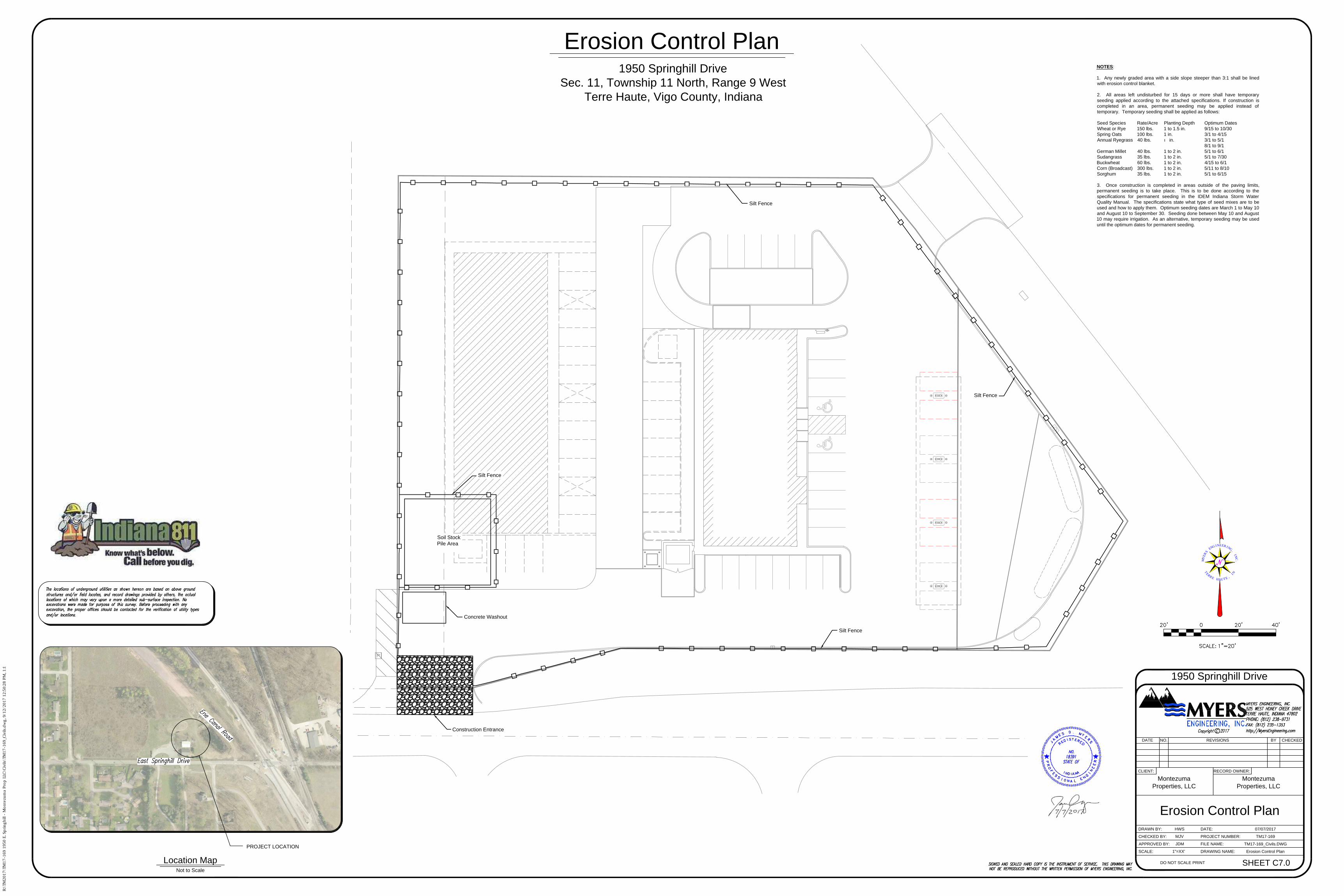
Construction Entrance
Soil Stock
Pile Area
Concrete Washout
Silt Fence
Silt Fence
Silt Fence
Silt Fence
Erosion Control Plan
MY
ERS
ENG INEER ING , INC
.
TERRE HAUTE , I N
NOTES:
1. Any newly graded area with a side slope steeper than 3:1 shall be lined
with erosion control blanket.
2. All areas left undisturbed for 15 days or more shall have temporary
seeding applied according to the attached specifications. If construction is
completed in an area, permanent seeding may be applied instead of
temporary. Temporary seeding shall be applied as follows:
Seed Species Rate/Acre Planting Depth Optimum Dates
Wheat or Rye 150 lbs. 1 to 1.5 in. 9/15 to 10/30
Spring Oats 100 lbs. 1 in. 3/1 to 4/15
Annual Ryegrass 40 lbs. ¼ in. 3/1 to 5/1
8/1 to 9/1
German Millet 40 lbs. 1 to 2 in. 5/1 to 6/1
Sudangrass 35 lbs. 1 to 2 in. 5/1 to 7/30
Buckwheat 60 lbs. 1 to 2 in. 4/15 to 6/1
Corn (Broadcast) 300 lbs. 1 to 2 in. 5/11 to 8/10
Sorghum 35 lbs. 1 to 2 in. 5/1 to 6/15
3. Once construction is completed in areas outside of the paving limits,
permanent seeding is to take place. This is to be done according to the
specifications for permanent seeding in the IDEM Indiana Storm Water
Quality Manual. The specifications state what type of seed mixes are to be
used and how to apply them. Optimum seeding dates are March 1 to May 10
and August 10 to September 30. Seeding done between May 10 and August
10 may require irrigation. As an alternative, temporary seeding may be used
until the optimum dates for permanent seeding.
PROJECT LOCATION
Not to Scale
Location Map
Erosion Control Plan
1"=XX' Erosion Control Plan
SHEET C7.0
1950 Springhill Drive
Sec. 11, Township 11 North, Range 9 West
Terre Haute, Vigo County, Indiana
HWS
MJV
JDM
Montezuma
Properties, LLC
1950 Springhill Drive
SCALE:
APPROVED BY:
CHECKED BY:
DRAWN BY:
DRAWING NAME:
FILE NAME:
PROJECT NUMBER:
RECORD OWNER:CLIENT:
DATE NO. REVISIONS BY CHECKED
TM17-169_Civils.DWG
TM17-169
07/07/2017
DO NOT SCALE PRINT
DATE:
Montezuma
Properties, LLC
R:\TM
2017\TM
17-169 1950 E. Sp
rin
gh
ill - M
on
tezu
ma P
ro
p LLC
\C
ivils\TM
17-169_C
ivils.d
wg
, 9/12/2017 12:50:28 P
M, 1:1
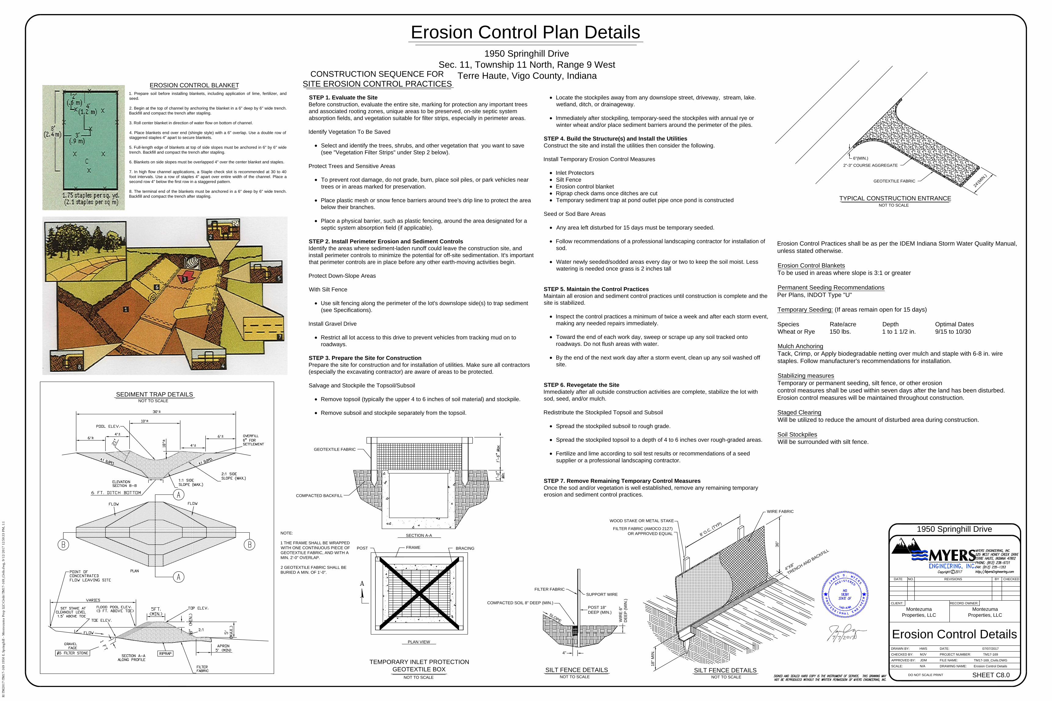
GEOTEXTILE FABRIC
COMPACTED BACKFILL
NOTE:
1 THE FRAME SHALL BE WRAPPED
WITH ONE CONTINUOUS PIECE OF
GEOTEXTILE FABRIC, AND WITH A
MIN. 2'-0" OVERLAP.
2 GEOTEXTILE FABRIC SHALL BE
BURIED A MIN. OF 1'-0".
FRAME
BRACINGPOST
NOT TO SCALE
TEMPORARY INLET PROTECTION
GEOTEXTILE BOX
SECTION A-A
PLAN VIEW
Erosion Control Plan Details
6"(MIN.)
2"-3" COURSE AGGREGATE
GEOTEXTILE FABRIC
2
4
'
(
M
I
N
.
)
SUPPORT WIRE
FILTER FABRIC
S
L
O
P
E
4"
1. Prepare soil before installing blankets, including application of lime, fertilizer, and
seed.
2. Begin at the top of channel by anchoring the blanket in a 6" deep by 6" wide trench.
Backfill and compact the trench after stapling.
3. Roll center blanket in direction of water flow on bottom of channel.
4. Place blankets end over end (shingle style) with a 6" overlap. Use a double row of
staggered staples 4" apart to secure blankets.
5. Full-length edge of blankets at top of side slopes must be anchored in 6" by 6" wide
trench. Backfill and compact the trench after stapling.
6. Blankets on side slopes must be overlapped 4" over the center blanket and staples.
7. In high flow channel applications, a Staple check slot is recommended at 30 to 40
foot intervals. Use a row of staples 4" apart over entire width of the channel. Place a
second row 4" below the first row in a staggered pattern.
8. The terminal end of the blankets must be anchored in a 6" deep by 6" wide trench.
Backfill and compact the trench after stapling.
CONSTRUCTION SEQUENCE FOR
SITE EROSION CONTROL PRACTICES
NOT TO SCALE
TYPICAL CONSTRUCTION ENTRANCE
NOT TO SCALE
SILT FENCE DETAILS
COMPACTED SOIL 8" DEEP (MIN.)
POST 18"
DEEP (MIN.)
WIR
E 6
"
DE
EP
(M
IN
.)
EROSION CONTROL BLANKET
NOT TO SCALE
SILT FENCE DETAILS
WOOD STAKE OR METAL STAKE
FILTER FABRIC (AMOCO 2127)
OR APPROVED EQUAL
8
'
O
.
C
.
(
T
Y
P
)
WIRE FABRIC
36
"
4
"
X
8
"
T
R
E
N
C
H
A
N
D
B
A
C
K
F
I
L
L
18
" M
IN
.
NOT TO SCALE
SEDIMENT TRAP DETAILS
STEP 1. Evaluate the Site
Before construction, evaluate the entire site, marking for protection any important trees
and associated rooting zones, unique areas to be preserved, on-site septic system
absorption fields, and vegetation suitable for filter strips, especially in perimeter areas.
Identify Vegetation To Be Saved
· Select and identify the trees, shrubs, and other vegetation that you want to save
(see "Vegetation Filter Strips" under Step 2 below).
Protect Trees and Sensitive Areas
· To prevent root damage, do not grade, burn, place soil piles, or park vehicles near
trees or in areas marked for preservation.
· Place plastic mesh or snow fence barriers around tree's drip line to protect the area
below their branches.
· Place a physical barrier, such as plastic fencing, around the area designated for a
septic system absorption field (if applicable).
STEP 2. Install Perimeter Erosion and Sediment Controls
Identify the areas where sediment-laden runoff could leave the construction site, and
install perimeter controls to minimize the potential for off-site sedimentation. It's important
that perimeter controls are in place before any other earth-moving activities begin.
Protect Down-Slope Areas
With Silt Fence
· Use silt fencing along the perimeter of the lot's downslope side(s) to trap sediment
(see Specifications).
Install Gravel Drive
· Restrict all lot access to this drive to prevent vehicles from tracking mud on to
roadways.
STEP 3. Prepare the Site for Construction
Prepare the site for construction and for installation of utilities. Make sure all contractors
(especially the excavating contractor) are aware of areas to be protected.
Salvage and Stockpile the Topsoil/Subsoil
· Remove topsoil (typically the upper 4 to 6 inches of soil material) and stockpile.
· Remove subsoil and stockpile separately from the topsoil.
· Locate the stockpiles away from any downslope street, driveway, stream, lake.
wetland, ditch, or drainageway.
· Immediately after stockpiling, temporary-seed the stockpiles with annual rye or
winter wheat and/or place sediment barriers around the perimeter of the piles.
STEP 4. Build the Structure(s) and Install the Utilities
Construct the site and install the utilities then consider the following.
Install Temporary Erosion Control Measures
· Inlet Protectors
· Silt Fence
· Erosion control blanket
· Riprap check dams once ditches are cut
· Temporary sediment trap at pond outlet pipe once pond is constructed
Seed or Sod Bare Areas
· Any area left disturbed for 15 days must be temporary seeded.
· Follow recommendations of a professional landscaping contractor for installation of
sod.
· Water newly seeded/sodded areas every day or two to keep the soil moist. Less
watering is needed once grass is 2 inches tall
STEP 5. Maintain the Control Practices
Maintain all erosion and sediment control practices until construction is complete and the
site is stabilized.
· Inspect the control practices a minimum of twice a week and after each storm event,
making any needed repairs immediately.
· Toward the end of each work day, sweep or scrape up any soil tracked onto
roadways. Do not flush areas with water.
· By the end of the next work day after a storm event, clean up any soil washed off
site.
STEP 6. Revegetate the Site
Immediately after all outside construction activities are complete, stabilize the lot with
sod, seed, and/or mulch.
Redistribute the Stockpiled Topsoil and Subsoil
· Spread the stockpiled subsoil to rough grade.
· Spread the stockpiled topsoil to a depth of 4 to 6 inches over rough-graded areas.
· Fertilize and lime according to soil test results or recommendations of a seed
supplier or a professional landscaping contractor.
STEP 7. Remove Remaining Temporary Control Measures
Once the sod and/or vegetation is well established, remove any remaining temporary
erosion and sediment control practices.
Erosion Control Practices shall be as per the IDEM Indiana Storm Water Quality Manual,
unless stated otherwise.
Erosion Control Blankets
To be used in areas where slope is 3:1 or greater
Permanent Seeding Recommendations
Per Plans, INDOT Type "U"
Temporary Seeding: (If areas remain open for 15 days)
Species Rate/acre Depth Optimal Dates
Wheat or Rye 150 lbs. 1 to 1 1/2 in. 9/15 to 10/30
Mulch Anchoring
Tack, Crimp, or Apply biodegradable netting over mulch and staple with 6-8 in. wire
staples. Follow manufacturer's recommendations for installation.
Stabilizing measures
Temporary or permanent seeding, silt fence, or other erosion
control measures shall be used within seven days after the land has been disturbed.
Erosion control measures will be maintained throughout construction.
Staged Clearing
Will be utilized to reduce the amount of disturbed area during construction.
Soil Stockpiles
Will be surrounded with silt fence.
Erosion Control Details
N/A Erosion Control Details
SHEET C8.0
1950 Springhill Drive
Sec. 11, Township 11 North, Range 9 West
Terre Haute, Vigo County, Indiana
HWS
MJV
JDM
Montezuma
Properties, LLC
1950 Springhill Drive
SCALE:
APPROVED BY:
CHECKED BY:
DRAWN BY:
DRAWING NAME:
FILE NAME:
PROJECT NUMBER:
RECORD OWNER:CLIENT:
DATE NO. REVISIONS BY CHECKED
TM17-169_Civils.DWG
TM17-169
07/07/2017
DO NOT SCALE PRINT
DATE:
Montezuma
Properties, LLC
R:\TM
2017\TM
17-169 1950 E. Sp
rin
gh
ill - M
on
tezu
ma P
ro
p LLC
\C
ivils\TM
17-169_C
ivils.d
wg
, 9/12/2017 12:50:33 P
M, 1:1
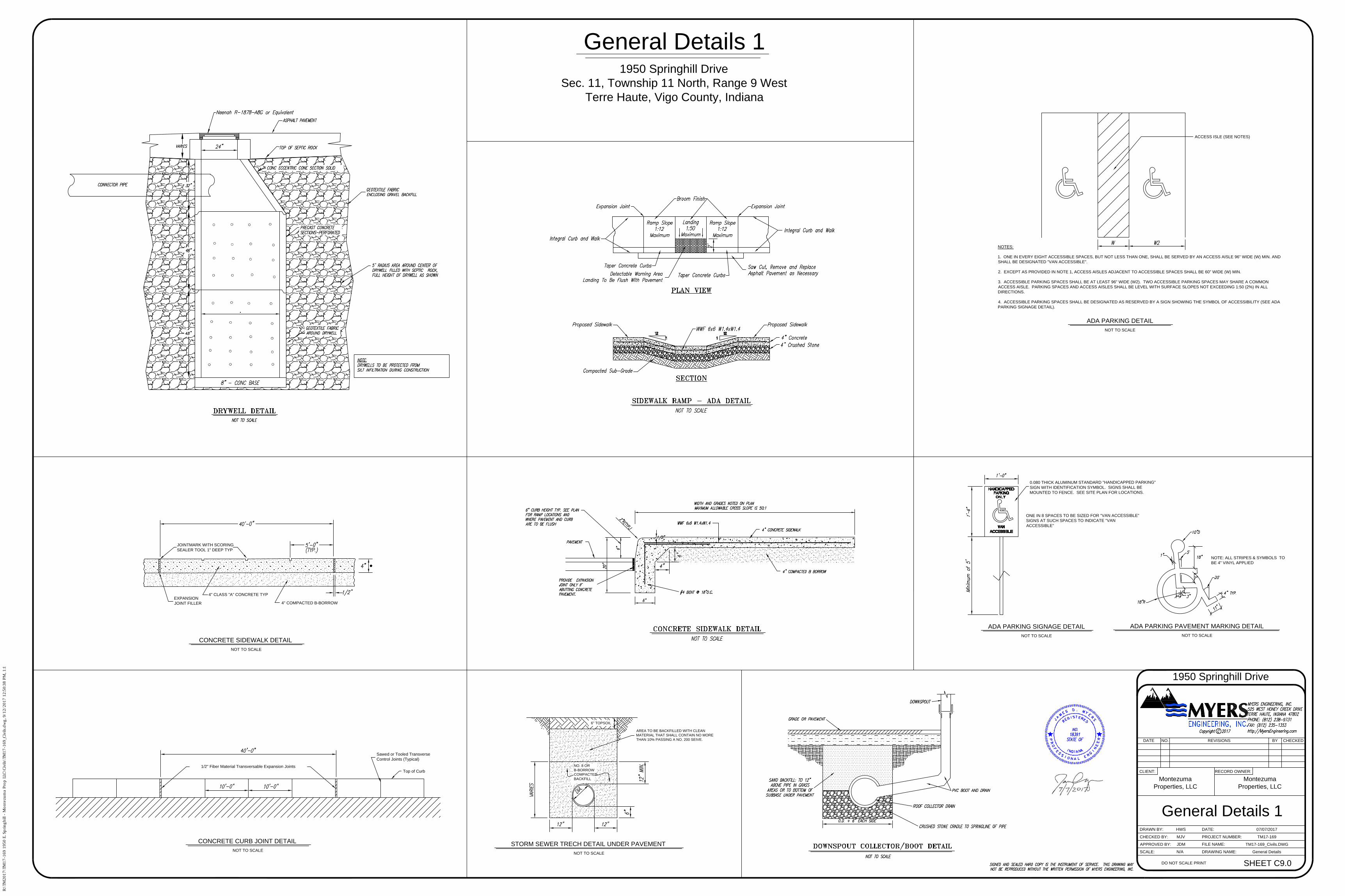
NOTES:
1. ONE IN EVERY EIGHT ACCESSIBLE SPACES, BUT NOT LESS THAN ONE, SHALL BE SERVED BY AN ACCESS AISLE 96" WIDE (W) MIN. AND
SHALL BE DESIGNATED "VAN ACCESSIBLE".
2. EXCEPT AS PROVIDED IN NOTE 1, ACCESS AISLES ADJACENT TO ACCESSIBLE SPACES SHALL BE 60" WIDE (W) MIN.
3. ACCESSIBLE PARKING SPACES SHALL BE AT LEAST 96" WIDE (W2). TWO ACCESSIBLE PARKING SPACES MAY SHARE A COMMON
ACCESS AISLE. PARKING SPACES AND ACCESS AISLES SHALL BE LEVEL WITH SURFACE SLOPES NOT EXCEEDING 1:50 (2%) IN ALL
DIRECTIONS.
4. ACCESSIBLE PARKING SPACES SHALL BE DESIGNATED AS RESERVED BY A SIGN SHOWING THE SYMBOL OF ACCESSIBILITY (SEE ADA
PARKING SIGNAGE DETAIL).
NOT TO SCALE
ACCESS ISLE (SEE NOTES)
Top of Curb
1/2" Fiber Material Transversable Expansion Joints
Sawed or Tooled Transverse
Control Joints (Typical)
NOT TO SCALE
NOT TO SCALE
NO. 8 OR
B-BORROW
COMPACTED
BACKFILL
6" TOPSOIL
AREA TO BE BACKFILLED WITH CLEAN
MATERIAL THAT SHALL CONTAIN NO MORE
THAN 10% PASSING A NO. 200 SEIVE.
STORM SEWER TRECH DETAIL UNDER PAVEMENT
ADA PARKING DETAIL
CONCRETE CURB JOINT DETAIL
General Details 1
N/A General Details
SHEET C9.0
General Details 1
1950 Springhill Drive
Sec. 11, Township 11 North, Range 9 West
Terre Haute, Vigo County, Indiana
HWS
MJV
JDM
Montezuma
Properties, LLC
1950 Springhill Drive
SCALE:
APPROVED BY:
CHECKED BY:
DRAWN BY:
DRAWING NAME:
FILE NAME:
PROJECT NUMBER:
RECORD OWNER:CLIENT:
DATE NO. REVISIONS BY CHECKED
TM17-169_Civils.DWG
TM17-169
07/07/2017
DO NOT SCALE PRINT
DATE:
Montezuma
Properties, LLC
0.080 THICK ALUMINUM STANDARD "HANDICAPPED PARKING"
SIGN WITH IDENTIFICATION SYMBOL. SIGNS SHALL BE
MOUNTED TO FENCE. SEE SITE PLAN FOR LOCATIONS.
ONE IN 8 SPACES TO BE SIZED FOR "VAN ACCESSIBLE"
SIGNS AT SUCH SPACES TO INDICATE "VAN
ACCESSIBLE"
NOT TO SCALE
NOTE: ALL STRIPES & SYMBOLS TO
BE 4" VINYL APPLIED
NOT TO SCALE
ADA PARKING SIGNAGE DETAILADA PARKING PAVEMENT MARKING DETAIL
NOT TO SCALE
CONCRETE SIDEWALK DETAIL
EXPANSION
JOINT FILLER
4" CLASS "A" CONCRETE TYP
4" COMPACTED B-BORROW
JOINTMARK WITH SCORING
SEALER TOOL 1" DEEP TYP
R:\TM
2017\TM
17-169 1950 E. Sp
rin
gh
ill - M
on
tezu
ma P
ro
p LLC
\C
ivils\TM
17-169_C
ivils.d
wg
, 9/12/2017 12:50:38 P
M, 1:1
General Details 2
N/A General Details
SHEET C10.0
General Details 2
EXISTING 8"
FORCE MAIN
4' MIN DEPTH
TO BE FIELD VERIFY
NOT TO SCALE
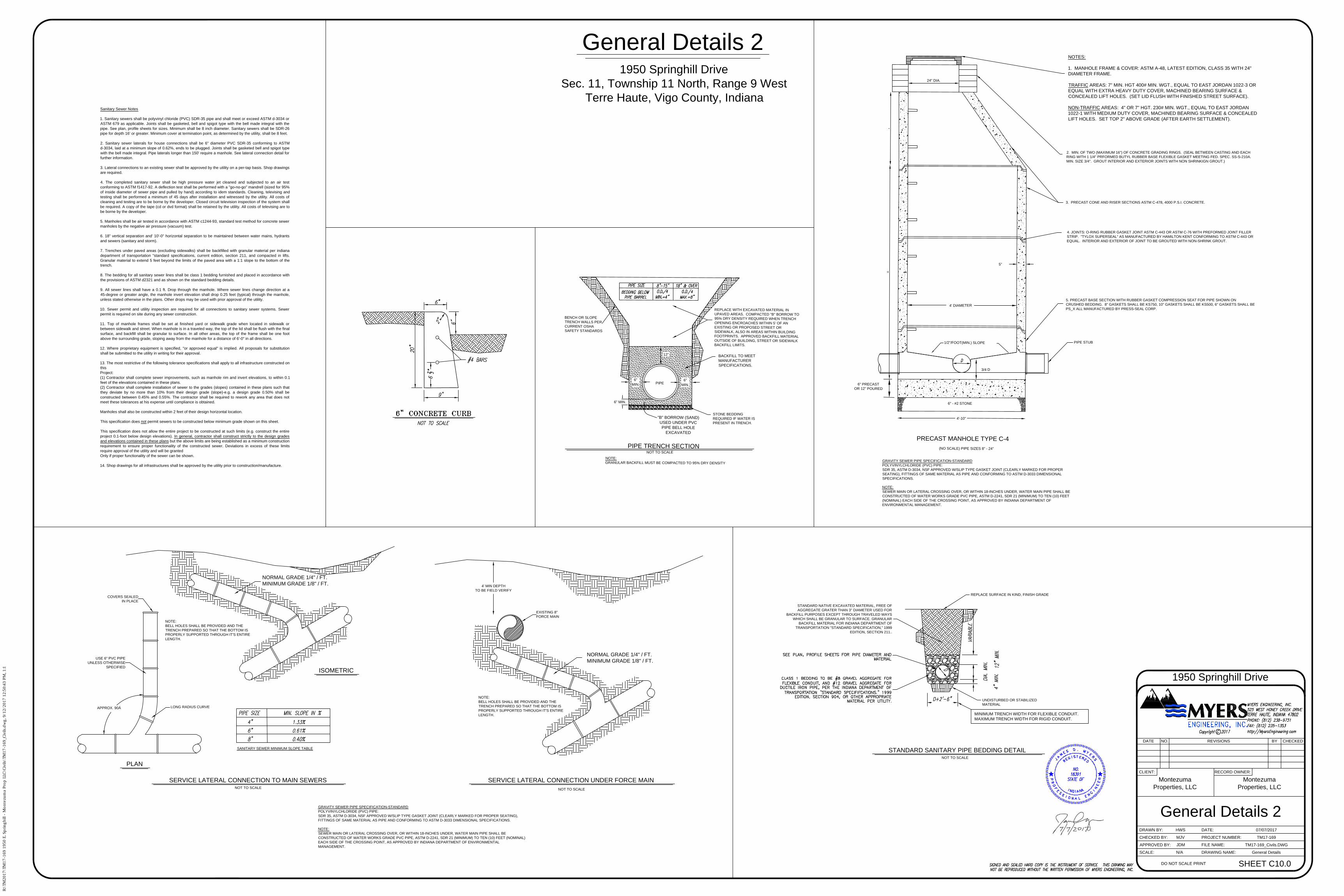
GRAVITY SEWER PIPE SPECIFICATION-STANDARD
POLYVINYLCHLORIDE (PVC) PIPE:
SDR 35, ASTM D-3034, NSF APPROVED W/SLIP TYPE GASKET JOINT (CLEARLY MARKED FOR PROPER
SEATING), FITTINGS OF SAME MATERIAL AS PIPE AND CONFORMING TO ASTM D-3033 DIMENSIONAL
SPECIFICATIONS.
NOTE:
SEWER MAIN OR LATERAL CROSSING OVER, OR WITHIN 18-INCHES UNDER, WATER MAIN PIPE SHALL BE
CONSTRUCTED OF WATER WORKS GRADE PVC PIPE, ASTM D-2241, SDR 21 (MINIMUM) TO TEN (10) FEET
(NOMINAL) EACH SIDE OF THE CROSSING POINT, AS APPROVED BY INDIANA DEPARTMENT OF
ENVIRONMENTAL MANAGEMENT.
NOTES:
1. MANHOLE FRAME & COVER: ASTM A-48, LATEST EDITION, CLASS 35 WITH 24"
DIAMETER FRAME.
TRAFFIC AREAS: 7" MIN. HGT 400# MIN. WGT., EQUAL TO EAST JORDAN 1022-3 OR
EQUAL WITH EXTRA HEAVY DUTY COVER, MACHINED BEARING SURFACE &
CONCEALED LIFT HOLES. (SET LID FLUSH WITH FINISHED STREET SURFACE).
NON-TRAFFIC AREAS: 4" OR 7" HGT. 230# MIN. WGT., EQUAL TO EAST JORDAN
1022-1 WITH MEDIUM DUTY COVER, MACHINED BEARING SURFACE & CONCEALED
LIFT HOLES. SET TOP 2" ABOVE GRADE (AFTER EARTH SETTLEMENT).
1/2"/FOOT(MIN.) SLOPE
4' DIAMETER
6" - #2 STONE
(NO SCALE) PIPE SIZES 8" - 24"
2. MIN. OF TWO (MAXIMUM 16") OF CONCRETE GRADING RINGS. (SEAL BETWEEN CASTING AND EACH
RING WITH 1 1/4" PRFORMED BUTYL RUBBER BASE FLEXIBLE GASKET MEETING FED. SPEC. SS-S-210A.
MIN. SIZE 3/4". GROUT INTERIOR AND EXTERIOR JOINTS WITH NON SHRINKIGN GROUT.)
3. PRECAST CONE AND RISER SECTIONS ASTM C-478, 4000 P.S.I. CONCRETE.
4. JOINTS: O-RING RUBBER GASKET JOINT ASTM C-443 OR ASTM C-76 WITH PREFORMED JOINT FILLER
STRIP. "TYLOX SUPERSEAL" AS MANUFACTURED BY HAMILTON KENT CONFORMING TO ASTM C-443 OR
EQUAL. INTERIOR AND EXTERIOR OF JOINT TO BE GROUTED WITH NON-SHRINK GROUT.
6" PRECAST
OR 12" POURED
5. PRECAST BASE SECTION WITH RUBBER GASKET COMPRESSION SEAT FOR PIPE SHOWN ON
CRUSHED BEDDING. 8" GASKETS SHALL BE KS750, 10" GASKETS SHALL BE KS500, 6" GASKETS SHALL BE
PS_X ALL MANUFACTURED BY PRESS-SEAL CORP.
3/4 D
PIPE STUB
4'-10"
5"
24" DIA.
APPROX. 90°
GRAVITY SEWER PIPE SPECIFICATION-STANDARD
POLYVINYLCHLORIDE (PVC) PIPE:
SDR 35, ASTM D-3034, NSF APPROVED W/SLIP TYPE GASKET JOINT (CLEARLY MARKED FOR PROPER SEATING),
FITTINGS OF SAME MATERIAL AS PIPE AND CONFORMING TO ASTM D-3033 DIMENSIONAL SPECIFICATIONS.
NOTE:
SEWER MAIN OR LATERAL CROSSING OVER, OR WITHIN 18-INCHES UNDER, WATER MAIN PIPE SHALL BE
CONSTRUCTED OF WATER WORKS GRADE PVC PIPE, ASTM D-2241, SDR 21 (MINIMUM) TO TEN (10) FEET (NOMINAL)
EACH SIDE OF THE CROSSING POINT, AS APPROVED BY INDIANA DEPARTMENT OF ENVIRONMENTAL
MANAGEMENT.
NORMAL GRADE 1/4" / FT.
MINIMUM GRADE 1/8" / FT.
LONG RADIUS CURVE
COVERS SEALED
IN PLACE
USE 6" PVC PIPE
UNLESS OTHERWISE
SPECIFIED
NOT TO SCALE
NOTE:
BELL HOLES SHALL BE PROVIDED AND THE
TRENCH PREPARED SO THAT THE BOTTOM IS
PROPERLY SUPPORTED THROUGH IT'S ENTIRE
LENGTH.
STANDARD NATIVE EXCAVATED MATERIAL, FREE OF
AGGREGATE GRATER THAN 3" DIAMETER USED FOR
BACKFILL PURPOSES EXCEPT THROUGH TRAVELED WAYS
WHICH SHALL BE GRANULAR TO SURFACE. GRANULAR
BACKFILL MATERIAL FOR INDIANA DEPARTMENT OF
TRANSPORTATION "STANDARD SPECIFICATION," 1999
EDITION, SECTION 211..
REPLACE SURFACE IN KIND, FINISH GRADE
UNDISTURBED OR STABILIZED
MATERIAL
MINIMUM TRENCH WIDTH FOR FLEXIBLE CONDUIT.
MAXIMUM TRENCH WIDTH FOR RIGID CONDUIT.
SANITARY SEWER MINIMUM SLOPE TABLE
BENCH OR SLOPE
TRENCH WALLS PER
CURRENT OSHA
SAFETY STANDARDS
REPLACE WITH EXCAVATED MATERIAL IN
UPAVED AREAS. COMPACTED "B" BORROW TO
95% DRY DENSITY REQUIRED WHEN TRENCH
OPENING ENCROACHES WITHIN 5' OF AN
EXISTING OR PROPOSED STREET OR
SIDEWALK, ALSO IN AREAS WITHIN BUILDING
FOOTPRINTS. APPROVED BACKFILL MATERIAL
OUTSIDE OF BUILDING, STREET OR SIDEWALK
BACKFILL LIMITS.
"B" BORROW (SAND)
USED UNDER PVC
PIPE BELL HOLE
EXCAVATED
6" MIN.
NOTE:
GRANULAR BACKFILL MUST BE COMPACTED TO 95% DRY DENSITY
STONE BEDDING
REQUIRED IF WATER IS
PRESENT IN TRENCH.
BACKFILL TO MEET
MANUFACTURER
SPECIFICATIONS.
6"
MIN.
6"
MIN.
12"
Sanitary Sewer Notes
1. Sanitary sewers shall be polyvinyl chloride (PVC) SDR-35 pipe and shall meet or exceed ASTM d-3034 or
ASTM 679 as applicable. Joints shall be gasketed, bell and spigot type with the bell made integral with the
pipe. See plan, profile sheets for sizes. Minimum shall be 8 inch diameter. Sanitary sewers shall be SDR-26
pipe for depth 16' or greater. Minimum cover at termination point, as determined by the utility, shall be 8 feet.
2. Sanitary sewer laterals for house connections shall be 6" diameter PVC SDR-35 conforming to ASTM
d-3034, laid at a minimum slope of 0.62%, ends to be plugged. Joints shall be gasketed bell and spigot type
with the bell made integral. Pipe laterals longer than 150' require a manhole. See lateral connection detail for
further information.
3. Lateral connections to an existing sewer shall be approved by the utility on a per-tap basis. Shop drawings
are required.
4. The completed sanitary sewer shall be high pressure water jet cleaned and subjected to an air test
conforming to ASTM f1417-92. A deflection test shall be performed with a "go-no-go" mandrell (sized for 95%
of inside diameter of sewer pipe and pulled by hand) according to idem standards. Cleaning, televising and
testing shall be performed a minimum of 45 days after installation and witnessed by the utility. All costs of
cleaning and testing are to be borne by the developer. Closed circuit television inspection of the system shall
be required. A copy of the tape (cd or dvd format) shall be retained by the utility. All costs of televising are to
be borne by the developer.
5. Manholes shall be air tested in accordance with ASTM c1244-93, standard test method for concrete sewer
manholes by the negative air pressure (vacuum) test.
6. 18" vertical separation and' 10'-0" horizontal separation to be maintained between water mains, hydrants
and sewers (sanitary and storm).
7. Trenches under paved areas (excluding sidewalks) shall be backfilled with granular material per indiana
department of transportation "standard specifications, current edition, section 211, and compacted in lifts.
Granular material to extend 5 feet beyond the limits of the paved area with a 1:1 slope to the bottom of the
trench.
8. The bedding for all sanitary sewer lines shall be class 1 bedding furnished and placed in accordance with
the provisions of ASTM d2321 and as shown on the standard bedding details.
9. All sewer lines shall have a 0.1 ft. Drop through the manhole. Where sewer lines change direction at a
45-degree or greater angle, the manhole invert elevation shall drop 0.25 feet (typical) through the manhole,
unless stated otherwise in the plans. Other drops may be used with prior approval of the utility.
10. Sewer permit and utility inspection are required for all connections to sanitary sewer systems. Sewer
permit is required on site during any sewer construction.
11. Top of manhole frames shall be set at finished yard or sidewalk grade when located in sidewalk or
between sidewalk and street. When manhole is in a traveled way, the top of the lid shall be flush with the final
surface, and backfill shall be granular to surface. In all other areas, the top of the frame shall be one foot
above the surrounding grade, sloping away from the manhole for a distance of 6'-0" in all directions.
12. Where proprietary equipment is specified, "or approved equal" is implied. All proposals for substitution
shall be submitted to the utility in writing for their approval.
13. The most restrictive of the following tolerance specifications shall apply to all infrastructure constructed on
this
Project:
(1) Contractor shall complete sewer improvements, such as manhole rim and invert elevations, to within 0.1
feet of the elevations contained in these plans.
(2) Contractor shall complete installation of sewer to the grades (slopes) contained in these plans such that
they deviate by no more than 10% from their design grade (slope)-e.g. a design grade 0.50% shall be
constructed between 0.45% and 0.55%. The contractor shall be required to rework any area that does not
meet these tolerances at his expense until compliance is obtained.
Manholes shall also be constructed within 2 feet of their design horizontal location.
This specification does not permit sewers to be constructed below minimum grade shown on this sheet.
This specification does not allow the entire project to be constructed at such limits (e.g. construct the entire
project 0.1-foot below design elevations). In general, contractor shall construct strictly to the design grades
and elevations contained in these plans but the above limits are being established as a minimum construction
requirement to ensure proper functionality of the constructed sewer. Deviations in excess of these limits
require approval of the utility and will be granted
Only if proper functionality of the sewer can be shown.
14. Shop drawings for all infrastructures shall be approved by the utility prior to construction/manufacture.
PRECAST MANHOLE TYPE C-4
PIPE TRENCH SECTION
STANDARD SANITARY PIPE BEDDING DETAIL
NOT TO SCALE
NOT TO SCALE
SERVICE LATERAL CONNECTION TO MAIN SEWERS
ISOMETRIC
PLAN
SERVICE LATERAL CONNECTION UNDER FORCE MAIN
NOTE:
BELL HOLES SHALL BE PROVIDED AND THE
TRENCH PREPARED SO THAT THE BOTTOM IS
PROPERLY SUPPORTED THROUGH IT'S ENTIRE
LENGTH.
NORMAL GRADE 1/4" / FT.
MINIMUM GRADE 1/8" / FT.
PIPE
1950 Springhill Drive
Sec. 11, Township 11 North, Range 9 West
Terre Haute, Vigo County, Indiana
HWS
MJV
JDM
Montezuma
Properties, LLC
1950 Springhill Drive
SCALE:
APPROVED BY:
CHECKED BY:
DRAWN BY:
DRAWING NAME:
FILE NAME:
PROJECT NUMBER:
RECORD OWNER:CLIENT:
DATE NO. REVISIONS BY CHECKED
TM17-169_Civils.DWG
TM17-169
07/07/2017
DO NOT SCALE PRINT
DATE:
Montezuma
Properties, LLC
R:\TM
2017\TM
17-169 1950 E. Sp
rin
gh
ill - M
on
tezu
ma P
ro
p LLC
\C
ivils\TM
17-169_C
ivils.d
wg
, 9/12/2017 12:50:43 P
M, 1:1
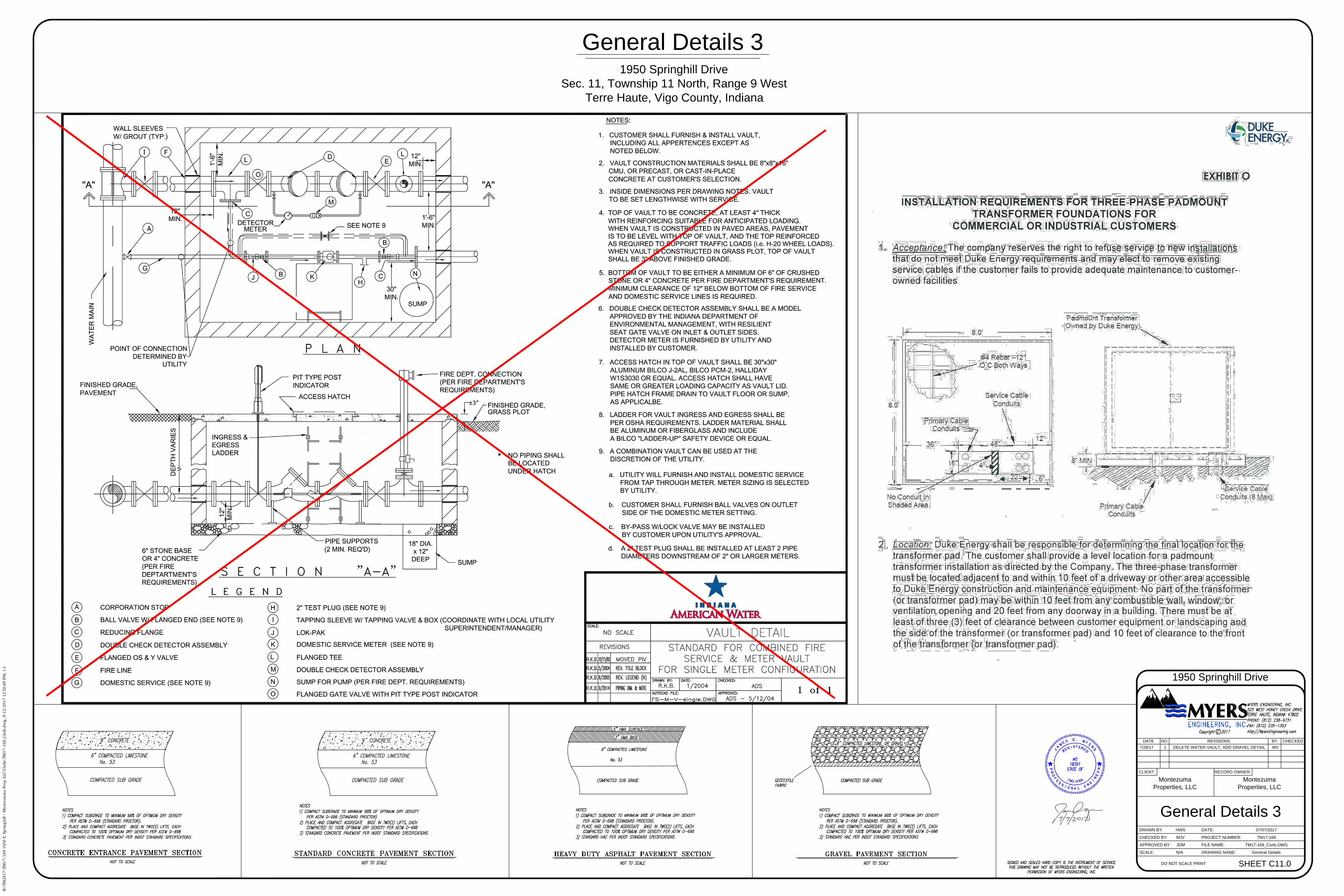
General Details 3
N/A General Details
SHEET C11.0
General Details 3
1950 Springhill Drive
Sec. 11, Township 11 North, Range 9 West
Terre Haute, Vigo County, Indiana
HWS
MJV
JDM
Montezuma
Properties, LLC
1950 Springhill Drive
SCALE:
APPROVED BY:
CHECKED BY:
DRAWN BY:
DRAWING NAME:
FILE NAME:
PROJECT NUMBER:
RECORD OWNER:CLIENT:
DATE NO. REVISIONS BY CHECKED
TM17-169_Civils.DWG
TM17-169
07/07/2017
DO NOT SCALE PRINT
DATE:
Montezuma
Properties, LLC
7/28/17 1 DELETE WATER VAULT, ADD GRAVEL DETAIL MV
R:\TM
2017\TM
17-169 1950 E. Sp
rin
gh
ill - M
on
tezu
ma P
ro
p LLC
\C
ivils\TM
17-169_C
ivils.d
wg
, 9/12/2017 12:50:49 P
M, 1:1
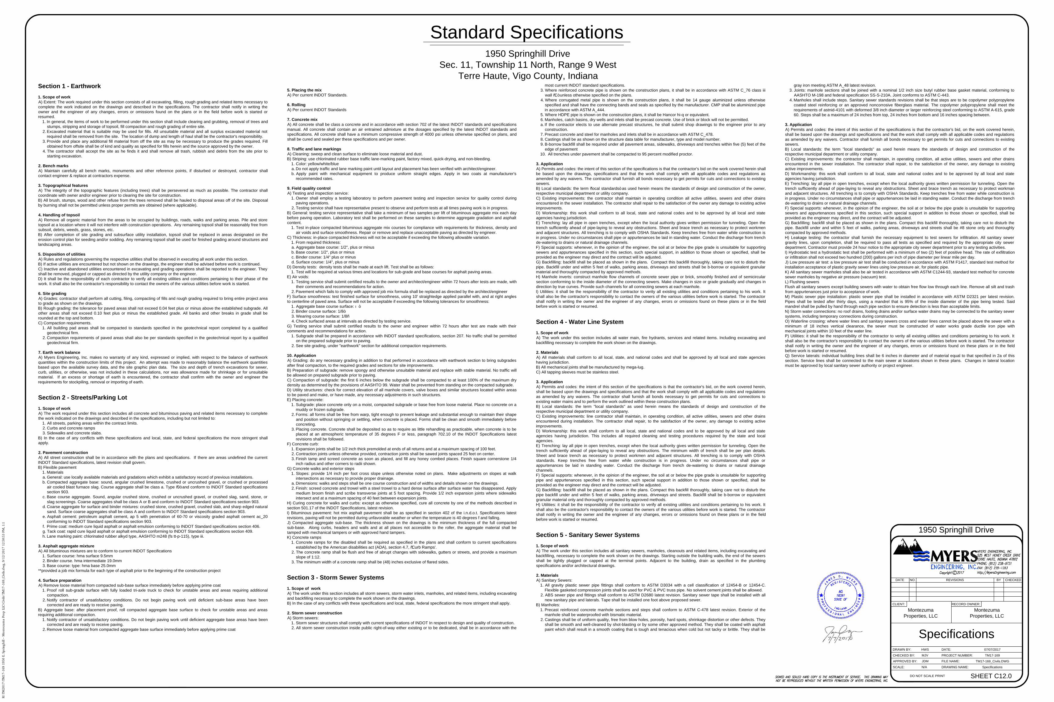
Standard Specifications
Specifications
N/A Specifications
SHEET C12.0
Section 1 - Earthwork
1. Scope of work
A) Extent: The work required under this section consists of all excavating, filling, rough grading and related items necessary to
complete the work indicated on the drawings and described in the specifications. The contractor shall notify in writing the
owner and the engineer of any changes, errors or omissions found on the plans or in the field before work is started or
resumed.
1. In general, the items of work to be performed under this section shall include clearing and grubbing, removal of trees and
stumps, stripping and storage of topsoil, fill compaction and rough grading of entire site.
2. Excavated material that is suitable may be used for fills. All unsuitable material and all surplus excavated material not
required shall be removed from the site. The location of dump and length of haul shall be the contractor's responsibility.
3. Provide and place any additional fill material from off the site as may be necessary to produce the grades required. Fill
obtained from offsite shall be of kind and quality as specified for fills herein and the source approved by the owner.
4. The contractor shall accept the site as he finds it and shall remove all trash, rubbish and debris from the site prior to
starting excavation.
2. Bench marks
A) Maintain carefully all bench marks, monuments and other reference points, if disturbed or destroyed, contractor shall
contact engineer & replace at contractors expense.
3. Topographical features
A) The integrity of the topographic features (including trees) shall be persevered as much as possible. The contractor shall
coordinate with owner and/or engineer prior to clearing the site for construction.
B) All brush, stumps, wood and other refuse from the trees removed shall be hauled to disposal areas off of the site. Disposal
by burning shall not be permitted unless proper permits are obtained (where applicable).
4. Handling of topsoil
A) Remove all organic material from the areas to be occupied by buildings, roads, walks and parking areas. Pile and store
topsoil at a location where it will not interfere with construction operations. Any remaining topsoil shall be reasonably free from
subsoil, debris, weeds, grass, stones, etc.
B) After completion of site grading and subsurface utility installation, topsoil shall be replaced in areas designated on the
erosion control plan for seeding and/or sodding. Any remaining topsoil shall be used for finished grading around structures and
landscaping areas.
5. Disposition of utilities
A) Rules and regulations governing the respective utilities shall be observed in executing all work under this section.
B) If active utilities are encountered but not shown on the drawings, the engineer shall be advised before work is continued.
C) Inactive and abandoned utilities encountered in excavating and grading operations shall be reported to the engineer. They
shall be removed, plugged or capped as directed by the utility company or the engineer.
D) It shall be the responsibility of each contractor to verify all existing utilities and conditions pertaining to their phase of the
work. It shall also be the contractor's responsibility to contact the owners of the various utilities before work is started.
6. Site grading
A) Grades: contractor shall perform all cutting, filing, compacting of fills and rough grading required to bring entire project area
to grade as shown on the drawings.
B) Rough grading: the tolerance for paved areas shall not exceed 0.04 feet plus or minus above the established subgrade. All
other areas shall not exceed 0.10 feet plus or minus the established grade. All banks and other breaks in grade shall be
rounded at the top and bottom.
C) Compaction requirements.
1. All building pad areas shall be compacted to standards specified in the geotechnical report completed by a qualified
geotechnical firm.
2. Compaction requirements of paved areas shall also be per standards specified in the geotechnical report by a qualified
geotechnical firm.
7. Earth work balance
A) Myers Engineering, Inc. makes no warranty of any kind, expressed or implied, with respect to the balance of earthwork
quantities within the construction limits of this project. An attempt was made to reasonably balance the earthwork quantities
based upon the available survey data, and the site graphic plan data. The size and depth of trench excavations for sewer,
curb, utilities, or otherwise, was not included in these calculations, nor was allowance made for shrinkage or for unsuitable
material. If an excess or shortage of earth is encountered, the contractor shall confirm with the owner and engineer the
requirements for stockpiling, removal or importing of earth.
Section 2 - Streets/Parking Lot
1. Scope of work
A) The work required under this section includes all concrete and bituminous paving and related items necessary to complete
the work indicated on the drawings and described in the specifications, including but not limited to:
1. All streets, parking areas within the contract limits.
2. Curbs and concrete ramps
3. Sidewalks and concrete slabs.
B) In the case of any conflicts with these specifications and local, state, and federal specifications the more stringent shall
apply.
2. Pavement construction
A) All street construction shall be in accordance with the plans and specifications. If there are areas undefined the current
INDOT Standard specifications, latest revision shall govern.
B) Flexible pavement
1. Materials
a. General: use locally available materials and gradations which exhibit a satisfactory record of previous installations.
b. Compacted aggregate base: sound, angular crushed limestone, crushed or uncrushed gravel, or crushed or processed
air cooled blast furnace slag. Course aggregate shall be class a. Type “0” and conform to INDOT Standard specifications
section 903.
c. Base course aggregate. Sound, angular crushed stone, crushed or uncrushed gravel, or crushed slag, sand, stone, or
slag screenings. Coarse aggregates shall be class A or B and conform to INDOT Standard specifications section 903.
d. Coarse aggregate for surface and binder mixtures: crushed stone, crushed gravel, crushed slab, and sharp edged natural
sand. Surface coarse aggregates shall be class A and conform to INDOT Standard specifications section 903.
e. Asphalt cement: petroleum asphalt cement, ap 5 with penetration of 60-70 or viscosity graded asphalt cement ac_20
conforming to INDOT Standard specifications section 903.
f. Prime coat: medium cure liquid asphalt or asphalt emulsion conforming to INDOT Standard specifications section 406.
g. Tack coat: rapid cure liquid asphalt or asphalt emulsion conforming to INDOT Standard specifications section 409.
h. Lane marking paint: chlorinated rubber alkyd type, AASHTO m248 (fs tt-p-115), type iii.
3. Asphalt aggregate mixture
A) All bituminous mixtures are to conform to current INDOT Specifications
1. Surface course: hma surface 9.5mm
2. Binder course. hma intermediate 19.0mm
3. Base course: type: hma base 25.0mm
**provided a job mix formula for each type of asphalt prior to the beginning of the construction project
4. Surface preparation
A) Remove loose material from compacted sub-base surface immediately before applying prime coat
1. Proof roll sub-grade surface with fully loaded tri-axle truck to check for unstable areas and areas requiring additional
compaction.
2. Notify contractor of unsatisfactory conditions. Do not begin paving work until deficient sub-base areas have been
corrected and are ready to receive paving.
B) Aggregate base: after placement proof, roll compacted aggregate base surface to check for unstable areas and areas
requiring additional compaction.
1. Notify contractor of unsatisfactory conditions. Do not begin paving work until deficient aggregate base areas have been
corrected and are ready to receive paving.
2. Remove loose material from compacted aggregate base surface immediately before applying prime coat
5. Placing the mix
A) Per current INDOT Standards.
6. Rolling
A) Per current INDOT Standards
7. Concrete mix
A) All concrete shall be class a concrete and in accordance with section 702 of the latest INDOT standards and specifications
manual. All concrete shall contain an air entrained admixture at the dosages specified by the latest INDOT standards and
specifications. All concrete shall have a minimum compressive strength of 4000 psi unless otherwise specified on plans, and
shall be cured and sealed per these specifications and per owner.
8. Traffic and lane markings
A) Cleaning: sweep and clean surface to eliminate loose material and dust.
B) Striping: use chlorinated rubber base traffic lane-marking paint, factory mixed, quick-drying, and non-bleeding.
1. Color: yellow/white/blue
a. Do not apply traffic and lane marking paint until layout and placement has been verified with architect/engineer.
b. Apply paint with mechanical equipment to produce uniform straight edges. Apply in two coats at manufacturer's
recommended rates.
9. Field quality control
A) Testing and inspection service:
1. Owner shall employ a testing laboratory to perform pavement testing and inspection service for quality control during
paving operations.
2. Testing service shall have representative present to observe and perform tests at all times paving work is in progress.
B) General: testing service representative shall take a minimum of two samples per lift of bituminous aggregate mix each day
before paving operation. Laboratory test shall be performed on these samples to determine aggregate gradation and asphalt
content.
1. Test in-place compacted bituminous aggregate mix courses for compliance with requirements for thickness, density and
air voids and surface smoothness. Repair or remove and replace unacceptable paving as directed by engineer.
C) Thickness: in-place compacted thickness will not be acceptable if exceeding the following allowable variation.
1. From required thickness:
a. Aggregate base course: 1/2", plus or minus
b. Base course: 1/2", plus or minus
c. Binder course: 1/4" plus or minus
d. Surface course: 1/4", plus or minus
D) Density tests: density tests shall be made at each lift. Test shall be as follows:
1. Test will be required at various times and locations for sub-grade and base courses for asphalt paving areas.
E) Air voids:
1. Testing service shall submit certified results to the owner and architect/engineer within 72 hours after tests are made, with
their comments and recommendations for action.
2. Pavement which fails to comply with approved job mix formula shall be replaced as directed by the architect/engineer
F) Surface smoothness: test finished surface for smoothness, using 10' straightedge applied parallel with, and at right angles
to centerline of paved area. Surface will not be acceptable if exceeding the following tolerances for smoothness:
1. Aggregate base course surface: ¼”
2. Binder course surface: 1/8”
3. Wearing course surface: 1/8“
4. Check surfaced areas at intervals as directed by testing service.
G) Testing service shall submit certified results to the owner and engineer within 72 hours after test are made with their
comments and recommendations for action.
1. Subgrade shall be prepared in accordance with INDOT standard specifications, section 207. No traffic shall be permitted
on the prepared subgrade prior to paving.
2. See site grading, under "earthwork" section for additional compaction requirements.
10. Application
A) Grading: do any necessary grading in addition to that performed in accordance with earthwork section to bring subgrades
after final compaction, to the required grades and sections for site improvements.
B) Preparation of subgrade: remove spongy and otherwise unsuitable material and replace with stable material. No traffic will
be allowed on prepared subgrade prior to paving.
C) Compaction of subgrade: the first 6 inches below the subgrade shall be compacted to at least 100% of the maximum dry
density as determined by the provisions of AASHTO 99. Water shall be prevented from standing on the compacted subgrade.
D) Utility structures: check for correct elevation of all manhole covers, valve boxes and similar structures located within areas
to be paved and make, or have made, any necessary adjustments in such structures.
E) Placing concrete:
1. Subgrade: place concrete only on a moist, compacted subgrade or base free from loose material. Place no concrete on a
muddy or frozen subgrade.
2. Forms: all forms shall be free from warp, tight enough to prevent leakage and substantial enough to maintain their shape
and position without springing or settling, when concrete is placed. Forms shall be clean and smooth immediately before
concreting.
3. Placing concrete. Concrete shall be deposited so as to require as little rehandling as practicable, when concrete is to be
placed at an atmospheric temperature of 35 degrees F or less, paragraph 702.10 of the INDOT Specifications latest
revisions shall be followed.
F) Concrete curb:
1. Expansion joints shall be 1/2 inch thick premolded at ends of all returns and at a maximum spacing of 100 feet.
2. Contraction joints unless otherwise provided, contraction joints shall be sawed joints spaced 25 feet on center.
3. Finish tamp and screed concrete as soon as placed, and fill any honey combed places. Finish square cornerstone 1/4
inch radius and other corners to radii shown.
G) Concrete walks and exterior steps
1. Slopes: provide 1/4 inch per foot cross slope unless otherwise noted on plans. Make adjustments on slopes at walk
intersections as necessary to provide proper drainage.
a. Dimensions: walks and steps shall be one course construction and of widths and details shown on the drawings.
2. Finish: screed concrete and trowel with a steel trowel to a hard dense surface after surface water has disappeared. Apply
medium broom finish and scribe transverse joints at 5 foot spacing. Provide 1/2 inch expansion joints where sidewalks
intersect and at a maximum spacing of 40 feet between expansion joints.
H) Curing concrete for walks and curbs: except as otherwise specified, cure all concrete by one of the methods described in
section 501.17 of the INDOT Specifications, latest revision.
I) Bituminous pavement: hot mix asphalt pavement shall be as specified in section 402 of the i.n.d.o.t. Specifications latest
revisions, paving will not be permitted during unfavorable weather or when the temperature is 40 degrees f and falling.
J) Compacted aggregate sub-base. The thickness shown on the drawings is the minimum thickness of the full compacted
sub-base. Along curbs, headers and walls and at all places not accessible to the roller, the aggregate material shall be
tamped with mechanical tampers or with approved hand tampers.
K) Concrete ramps
1. Concrete ramps for the disabled shall be required as specified in the plans and shall conform to current specifications
established by the American disabilities act (ADA), section 4.7, “Curb Ramps'.
2. The concrete ramp shall be flush and free of abrupt changes with sidewalks, gutters or streets, and provide a maximum
slope of 1:12.
3. The minimum width of a concrete ramp shall be (48) inches exclusive of flared sides.
Section 3 - Storm Sewer Systems
1. Scope of work
A) The work under this section includes all storm sewers, storm water inlets, manholes, and related items, including excavating
and backfilling necessary to complete the work shown on the drawings.
B) In the case of any conflicts with these specifications and local, state, federal specifications the more stringent shall apply.
2. Storm sewer construction
A) Storm sewers:
1. Storm sewer structures shall comply with current specifications of INDOT In respect to design and quality of construction.
2. All storm sewer construction inside public right-of-way either existing or to be dedicated, shall be in accordance with the
most current INDOT standard specifications.
3. Where reinforced concrete pipe is shown on the construction plans, it shall be in accordance with ASTM C_76 class iii
wall “C” unless otherwise specified on the plans.
4. Where corrugated metal pipe is shown on the construction plans, it shall be 14 gauge aluminized unless otherwise
specified and shall have the connecting bands and seals as specified by the manufacturer. CMP shall be aluminized pipe
in accordance with ASTM A_444.
5. Where HDPE pipe is shown on the construction plans, it shall be Hancor hi-q or equivalent.
6. Manholes, catch basins, dry wells and inlets shall be precast concrete. Use of brick or block will not be permitted.
a. If the contractor elects to use alternate precast structures, he shall submit shop drawings to the engineer prior to any
construction.
7. Precast concrete and steel for manholes and inlets shall be in accordance with ASTM C_478.
8. Castings shall be as shown on the structure data table for manufacturer, type and model number.
9. B-borrow backfill shall be required under all pavement areas, sidewalks, driveways and trenches within five (5) feet of the
edge of pavement
10. All trenches under pavement shall be compacted to 95 percent modified proctor.
3. Application
A) Permits and codes: the intent of this section of the specifications is that the contractor's bid on the work covered herein shall
be based upon the drawings, specifications and that the work shall comply with all applicable codes and regulations as
amended by any waivers. The contractor shall furnish all bonds necessary to get permits for cuts and connections to existing
sewers.
B) Local standards: the term “local standards” as used herein means the standards of design and construction of the owner,
respective municipal department or utility company.
C) Existing improvements: the contractor shall maintain in operating condition all active utilities, sewers and other drains
encountered in the sewer installation. The contractor shall repair to the satisfaction of the owner any damage to existing active
improvements.
D) Workmanship: this work shall conform to all local, state and national codes and to be approved by all local and state
agencies having jurisdiction.
E) Trenching: lay all pipe in open trenches, except when the local authority gives written permission for tunneling. Open the
trench sufficiently ahead of pipe-laying to reveal any obstructions. Sheet and brace trench as necessary to protect workmen
and adjacent structures. All trenching is to comply with OSHA Standards. Keep trenches free from water while construction is
in progress. Under no circumstances shall pipe or appurtenances be laid in standing water. Conduct the discharge from trench
de-watering to drains or natural drainage channels.
F) Special supports: whenever, in the opinion of the engineer, the soil at or below the pipe grade is unsuitable for supporting
sewers and appurtenances specified in this section, such special support, in addition to those shown or specified, shall be
provided as the engineer may direct and the contract will be adjusted.
G) Backfilling: backfill shall be placed as shown in the plans. Compact this backfill thoroughly, taking care not to disturb the
pipe. Backfill under and within 5 feet of walks, parking areas, driveways and streets shall be b-borrow or equivalent granular
material and thoroughly compacted by approved methods.
H) Manhole inverts: construct manhole flow channels of concrete sewer pipe or brick, smoothly finished and of semicircular
section conforming to the inside diameter of the connecting sewers. Make changes in size or grade gradually and changes in
direction by true curves. Provide such channels for all connecting sewers at each manhole.
I) Utilities: it shall be the responsibility of the contractor to verity all existing utilities and conditions pertaining to his work. It
shall also be the contractor's responsibility to contact the owners of the various utilities before work is started. The contractor
shall notify in writing the owner and the engineer of any changes, errors or omissions found on these plans or in the field
before work is started or resumed.
Section 4 - Water Line System
1. Scope of work
A) The work under this section includes all water main, fire hydrants, services and related items. Including excavating and
backfilling necessary to complete the work shown on the drawings.
2. Materials
A) All materials shall conform to all local, state, and national codes and shall be approved by all local and state agencies
having jurisdiction.
B) All mechanical joints shall be manufactured by mega-lug.
C) All tapping sleeves must be stainless steel.
3. Application
A) Permits and codes: the intent of this section of the specifications is that the contractor's bid, on the work covered herein,
shall be based upon the drawings and specifications and that the work shall comply with all applicable codes and regulations
as amended by any waivers. The contractor shall furnish all bonds necessary to get permits for cuts and connections to
existing water mains and to perform the work outlined within these construction plans.
B) Local standards: the term "local standards" as used herein means the standards of design and construction of the
respective municipal department or utility company.
C) Existing improvements: line contractor shall maintain, in operating condition, all active utilities, sewers and other drains
encountered during installation. The contractor shall repair, to the satisfaction of the owner, any damage to existing active
improvements.
D) Workmanship: this work shall conform to all local, state and national codes and to be approved by all local and state
agencies having jurisdiction. This includes all required cleaning and testing procedures required by the state and local
agencies.
E) Trenching: lay all pipe in open trenches, except when the local authority gives written permission for tunneling. Open the
trench sufficiently ahead of pipe-laying to reveal any obstructions. The minimum width of trench shall be per plan details.
Sheet and brace trench as necessary to protect workmen and adjacent structures. All trenching is to comply with OSHA
standards. Keep trenches free from water while construction is in progress. Under no circumstances shall pipe or
appurtenances be laid in standing water. Conduct the discharge from trench de-watering to drains or natural drainage
channels.
F) Special supports: whenever, in the opinion of the engineer, the soil at or below the pipe grade is unsuitable for supporting
pipe and appurtenances specified in this section, such special support in addition to those shown or specified, shall be
provided as the engineer may direct and the contract will be adjusted.
G) Backfilling: backfill shall be placed as shown in the plans. Compact this backfill thoroughly, taking care not to disturb the
pipe backfill under and within 5 feet of walks, parking areas, driveways and streets. Backfill shall be b-borrow or equivalent
granular material only and thoroughly compacted by approved methods.
H) Utilities: it shall be the responsibility of the contractor to verify all existing utilities and conditions pertaining to his work. It
shall also be the contractor's responsibility to contact the owners of the various utilities before work is started. The contractor
shall notify in writing the owner and the engineer of any changes, errors or omissions found on these plans or in the field
before work is started or resumed.
Section 5 - Sanitary Sewer Systems
1. Scope of work
A) The work under this section includes all sanitary sewers, manholes, cleanouts and related items, including excavating and
backfilling, necessary to complete the work shown on the drawings. Starting outside the building walls, the end of the sewers
shall be tightly plugged or capped at the terminal points. Adjacent to the building, drain as specified in the plumbing
specifications and/or architectural drawings.
2. Materials
A) Sanitary Sewers:
1. All gravity plastic sewer pipe fittings shall conform to ASTM D3034 with a cell classification of 12454-B or 12454-C.
Flexible gasketed compression joints shall be used for PVC & PVC truss pipe. No solvent cement joints shall be allowed.
2. ABS sewer pipe and fittings shall conform to ASTM D2680 latest revision. Sanitary sewer tape shall be installed with all
new sanitary pipe and laterals. Tape shall be installed one foot above proposed sewer.
B) Manholes:
1. Precast reinforced concrete manhole sections and steps shall conform to ASTM C-478 latest revision. Exterior of the
manhole shall be waterproofed with bismatic material.
2. Castings shall be of uniform quality, free from blow holes, porosity, hard spots, shrinkage distortion or other defects. They
shall be smooth and well-cleaned by shot-blasting or by some other approved method. They shall be coated with asphalt
paint which shall result in a smooth coating that is tough and tenacious when cold but not tacky or brittle. They shall be
gray iron meeting ASTM A_48 latest revision.
3. Joints: manhole sections shall be joined with a nominal 1/2 inch size butyl rubber base gasket material, conforming to
AASHTO M-198 and federal specification SS-S-210A. Joint conforms to ASTM C-443.
4. Manholes shall include steps. Sanitary sewer standards revisions shall be that steps are to be copolymer polypropylene
coated steel reinforcing or an approved noncorrosive fiberglass material. The copolymer polypropylene shall meet the
requirements of astnid-4101 with deformed 3/8 inch diameter or larger reinforcing steel conforming to ASTM A-615, grade
60. Steps shall be a maximum of 24 inches from top, 24 inches from bottom and 16 inches spacing between.
3. Application
A) Permits and codes: the intent of this section of the specifications is that the contractor's bid, on the work covered herein,
shall be based upon the drawings and specifications and that the work shall comply with all applicable codes and regulations
as amended by any waivers. Contractor shall furnish all bonds necessary to get permits for cuts and connections to existing
sewers.
B) Local standards: the term "local standards" as used herein means the standards of design and construction of the
respective municipal department or utility company.
C) Existing improvements: the contractor shall maintain, in operating condition, all active utilities, sewers and other drains
encountered in the sewer installation. The contractor shall repair, to the satisfaction of the owner, any damage to existing
active improvements.
D) Workmanship: this work shall conform to all local, state and national codes and to be approved by all local and state
agencies having jurisdiction.
E) Trenching: lay all pipe in open trenches, except when the local authority gives written permission for tunneling. Open the
trench sufficiently ahead of pipe-laying to reveal any obstructions. Sheet and brace trench as necessary to protect workman
and adjacent structures. All trenching is to comply with OSHA Standards. Keep trenches free from water while construction is
in progress. Under no circumstances shall pipe or appurtenances be laid in standing water. Conduct the discharge from trench
de-watering to drains or natural drainage channels.
F) Special supports: whenever, in the opinion of the engineer, the soil at or below the pipe grade is unsuitable for supporting
sewers and appurtenances specified in this section, such special support in addition to those shown or specified, shall be
provided as the engineer may direct, and the contract will be adjusted.
G) Backfilling: backfill shall be placed as shown in the plans. Compact this backfill thoroughly, taking care not to disturb the
pipe. Backfill under and within 5 feet of walks, parking areas, driveways and streets shall be #8 stone only and thoroughly
compacted by approved methods.
H) Leakage testing: the contractor shall furnish the necessary equipment to test sewers for infiltration. All sanitary sewer
gravity lines, upon completion, shall be required to pass all tests as specified and required by the appropriate city sewer
department. Contractor must provide 24 hour notice to the appropriate city sewer department prior to any testing activities.
I) Hydrostatic test a hydrostatic test shall be performed with a minimum of two (2) feet of positive head. The rate of exfiltration
or infiltration shall not exceed two hundred (200) gallons per inch of pipe diameter per linear mile per day.
J) Low pressure air test: a low pressure air test shall be conducted in accordance with ASTM F1417, standard test method for
installation acceptance of plastic gravity sewer lines using low pressure air, for plastic pipe.
K) All sanitary sewer manholes shall also be air tested in accordance with ASTM C1244-93, standard test method for concrete
sewer manholes by negative air pressure (vacuum) test.
L) Flushing sewers
Flush all sanitary sewers except building sewers with water to obtain free flow low through each line. Remove all silt and trash
from appurtenances just prior to acceptance of work.
M) Plastic sewer pipe installation: plastic sewer pipe shall be installed in accordance with ASTM D2321 per latest revision.
Pipes shall be tested after thirty days, using a mandrel that is 95% of the inside diameter of the pipe being tested. Said
mandrel shall be pulled by hand through each pipe section to ensure detection is less than acceptable limits.
N) Storm water connections: no roof drains, footing drains and/or surface water drains may be connected to the sanitary sewer
systems, including temporary connections during construction.
O) Waterline crossing: where water lines and sanitary sewers cross and water lines cannot be placed above the sewer with a
minimum of 18 inches vertical clearance, the sewer must be constructed of water works grade ductile iron pipe with
mechanical joints within 10 feet of the water line.
P) Utilities: it shall be the responsibility of the contractor to verity all existing utilities and conditions pertaining to his work. It
shall also be the contractor's responsibility to contact the owners of the various utilities before work is started. The contractor
shall notify in writing the owner and the engineer of any changes, errors or omissions found on these plans or in the field
before work is started or resumed.
Q) Service laterals: individual building lines shall be 6 inches in diameter and of material equal to that specified in 2a of this
section. Service lines shall be connected to the main sewer at locations shown in these plans. Changes in lateral location
must be approved by local sanitary sewer authority or project engineer.
1950 Springhill Drive
Sec. 11, Township 11 North, Range 9 West
Terre Haute, Vigo County, Indiana
HWS
MJV
JDM
Montezuma
Properties, LLC
1950 Springhill Drive
SCALE:
APPROVED BY:
CHECKED BY:
DRAWN BY:
DRAWING NAME:
FILE NAME:
PROJECT NUMBER:
RECORD OWNER:CLIENT:
DATE NO. REVISIONS BY CHECKED
TM17-169_Civils.DWG
TM17-169
07/07/2017
DO NOT SCALE PRINT
DATE:
Montezuma
Properties, LLC
R:\TM
2017\TM
17-169 1950 E. Sp
rin
gh
ill - M
on
tezu
ma P
ro
p LLC
\C
ivils\TM
17-169_C
ivils.d
wg
, 9/12/2017 12:50:53 P
M, 1:1