Embed Size (px)
Citation preview

TID and TSJ. William Gu
Data Acquisition
1. Trigger distribution scheme2. TID development3. TID in test setup4. TS development
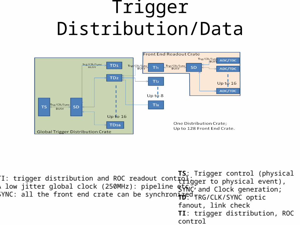
Trigger Distribution/Data Readout
TI: trigger distribution and ROC readout control;A low jitter global clock (250MHz): pipeline etc.;SYNC: all the front end crate can be synchronized.
TS: Trigger control (physical trigger to physical event), SYNC and Clock generation;TD: TRG/CLK/SYNC optic fanout, link checkTI: trigger distribution, ROC controlSD: TRG/CLK/SYNC fan out (VXS P0)

TID DevelopmentPrototype:
TS, TI, TD or combinations of these individual board functions. This is especially useful for test setups (detail next page)
Production: (one PCB, two assembly)Dedicated TI (one optic transceiver)Dedicated TD (does not drive P0)
Legacy compatibility:With a Mezz card, the TID/TI can
behave like an TI_rev2 board, which can connect to TS_Rev2

TID used in test setup
With TIDs, a system with up to nine crates can be setup. A two-crate system was tested extensively;
Limitation: “TS” trigger inputs: 6 (current firmware); 7 with firmware update;
TI_MASTERTI
TI

TS development
External Trigger INTwo 15-bit orFour 7-bit source synced
TS clock output, orQSFP (driving TI)
TS clock input, orQSFP (driving TI)
16 diff. inputs
12 diff. outputs
10 single-endedoutputs
VME64xVMEJTAG (PROM loading)
VXSTRG/CLOCK/SYNC(pulse mode or serialized mode)
6 x 4 LEDs board status
GTP trigger INTwo 15-bit, or four 7-bit source synced
Optional:Trigger to TD,Busy from TD

TS developmentTrigger: It can accepts up to 30 GTP inputs (from VME P2 backplane) , 30 external inputs (from front panel), and another 15 front panel inputs. It can also generate readout triggers from VME command. (>=) 10-bit trigger (event) types are supported. Every trigger input can be enabled, pre-scaled, and monitored by scalars.
Sync: With the fiber latency measurement (by TI), all the front end crate can be synced to within 4ns (one 250 MHz clock cycle).
Clock: the onboard 250 MHz oscillator, or external input
Backpressure (or DAQ flow control): with BUSY feedback, and status link (opposite link from the TRIGGER word), the DAQ can work in blocking mode, single event locking mode, or free running mode.

TS Development-- Trigger (event) Type lookup table scheme
15x8
15x8
MUX(with
priorities)
VME triggers
15x11
15x11
15x8
16x11
MxN M-bit input, N-bit output memory lookup table.The table is downloaded by software at startup
15
15
8
8
15x8
15x8
16x11
15
15
8
8
15
6
5
5
6
4
4
Trigger(event)Type
GTPTrigger
ExternalTrigger
Front Paneltrigger
>10