Embed Size (px)
Citation preview

HKS-Prozesstechnik GmbH
IIW International Conference on “Automation in Welding”16th/17th September, 2013 | Essen, Germany
IIW International Conference on “Automation in Welding”16th/17th September, 2013 | Essen, Germany
Thermal Weld Seam Inspection in Pipe Production Lines
Thermal Weld Seam Inspection in Pipe Production Lines
V. Schauder HKS-Prozesstechnik GmbH ,Germany
T. Köhler HKS-Prozesstechnik GmbH, Germany
B. Wenzl Wuppermann Austria GmbH, Austria
M. Prasek Rafter Equipment Cooperation, USA
M. Schmitt Baltec industries USA
V. Schauder HKS-Prozesstechnik GmbH ,Germany
T. Köhler HKS-Prozesstechnik GmbH, Germany
B. Wenzl Wuppermann Austria GmbH, Austria
M. Prasek Rafter Equipment Cooperation, USA
M. Schmitt Baltec industries USA

HKS-Prozesstechnik GmbH
Agenda
� Introduction
� Problems with current methods of NDT in tube production
� Development of a Thermoprofilescanner – A special robust and lens free thermo line camera
� Operation of a integrated NDT system based on the thermography
� Using passive thermography on a weld seam during the cooling phase
� Conclusion
HKS-Prozesstechnik GmbH
IntroductionIn 2007 we began to develop the following thermography system with the goal of finding the position of MAG seams and holes in TIG welding robot application. We knew that only measuring electric parameters (voltage, current) would not allow the detection of all welding failures. We sought new methods to find additional information about the seam.The idea was to measure the temperatures near the welding point. Only by developing our own thermo line camera (Thermoprofilescanner) could this be achieved. We learnt by doing, we measuring heat signatures and how to interpret them. Later in 2009 we began to apply this method to tube and pipe welding, and opened a new application field. We began to understand, that we were not only measure the surface temperature. What we do is really the applied passive thermography method. We now have the possibility to look inside the material, to see the penetration.
In this lecture we will explain this NDT method based on passive thermography and this equipment. It is very new and not yet a quality control standard anywhere in the world.
Approaches to Nondestructive inspection of welding quality Offline: Inspection in a special inspections station at the end of the production lineInline: Inspection during the production, near to the welding point
The inline inspection offers two big advantages:a) If occurs problems, the mill can stop and will not produce more faulty tubes . b) Based on the monitoring quality the machine parameters can be optimized continuously by the operator.
Typical problems can be prevented.
This method can only be used with inline inspection.
HKS-Prozesstechnik GmbH
Weldseam inspection in continuous seam tube mill
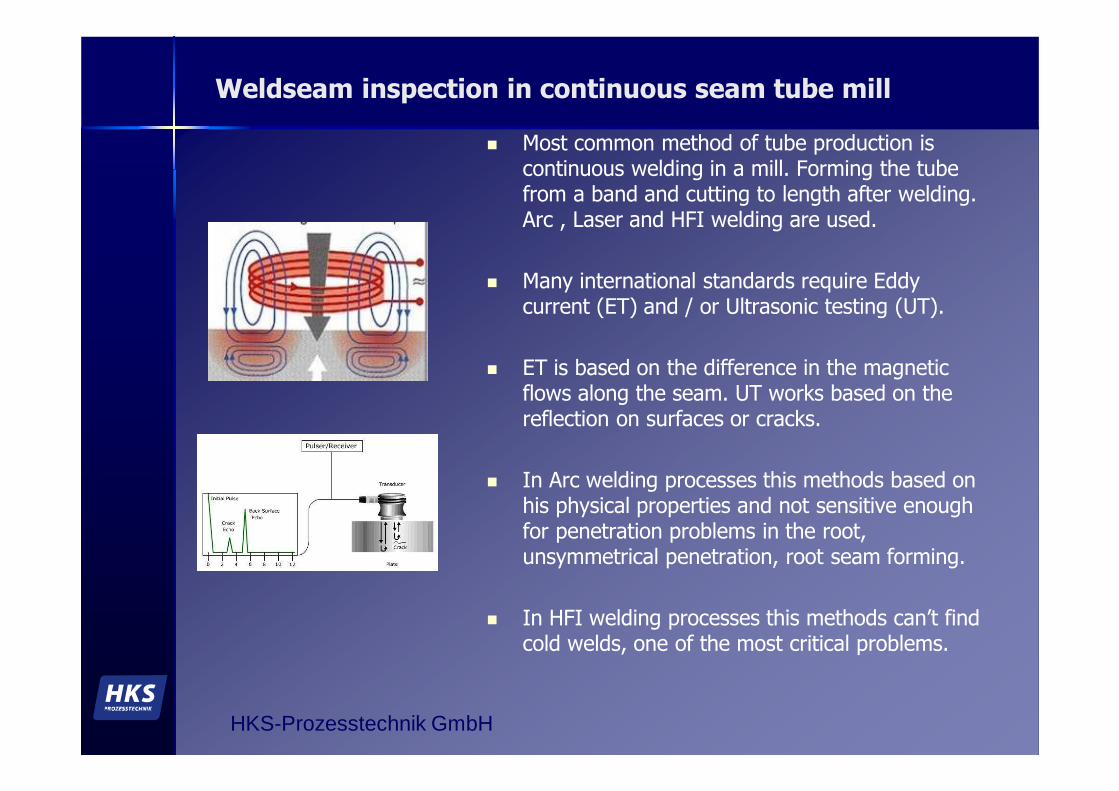
� Most common method of tube production is continuous welding in a mill. Forming the tube from a band and cutting to length after welding. Arc , Laser and HFI welding are used.
� Many international standards require Eddy current (ET) and / or Ultrasonic testing (UT).
� ET is based on the difference in the magnetic flows along the seam. UT works based on the reflection on surfaces or cracks.
� In Arc welding processes this methods based on his physical properties and not sensitive enough for penetration problems in the root, unsymmetrical penetration, root seam forming.
� In HFI welding processes this methods can’t find cold welds, one of the most critical problems.
HKS-Prozesstechnik GmbH
Heat and temperatures near the welding point
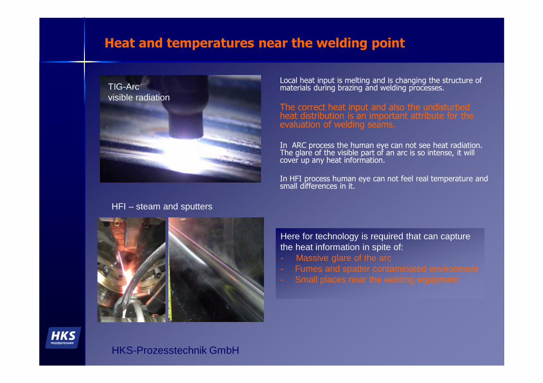
Local heat input is melting and is changing the structure of materials during brazing and welding processes.
The correct heat input and also the undisturbed heat distribution is an important attribute for the evaluation of welding seams.
In ARC process the human eye can not see heat radiation. The glare of the visible part of an arc is so intense, it will cover up any heat information.
In HFI process human eye can not feel real temperature and small differences in it.
TIG-Arcvisible radiation
Here for technology is required that can capture the heat information in spite of:- Massive glare of the arc - Fumes and spatter contaminated environment - Small places near the welding equipment
HFI – steam and sputters
HKS-Prozesstechnik GmbH
Real existing techniques and the problems in measuring temperatures near the welding point
1. Requirements for a thermo camera
– Wavelength < 2µm
– Frame or line rate not less 400 Hz
– Resolution in amplitude for measuring not less 14 bit
– => Currently available cameras with the required properties are very big, very expensive, very sensitive to contamination, not integrable
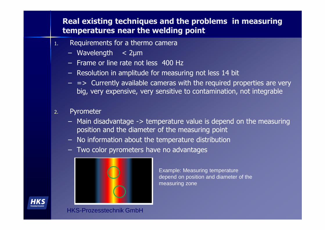
2. Pyrometer
– Main disadvantage -> temperature value is depend on the measuring position and the diameter of the measuring point
– No information about the temperature distribution
– Two color pyrometers have no advantages
Example: Measuring temperature depend on position and diameter of the measuring zone

HKS-Prozesstechnik GmbH
ThermoProfileScanner a special designed thermo line camera for welding applications
The Thermoprofilescanner is constantly capturing a thermo profile across the welding seam.
Thermo profile cross wise to the seam TIG
The Thermoprofilescanner is a lens free design, very compact , robust and measures the temperature in a line of 20 mm (standard) with a work distance of 15 to 300 mm.
Scan frequency >= 400 Profiles/s and shutter speeds of a single line of 50 µs allowing a resolution of up to15 m/min (Laser / arc welding) or in HFI processes of 180 m/min.
Features of the TPS :- self protecting gas shield, - mechanical safety shutter,- water cooling,- constant inside temperature regulation, - anti spatter shields or self cleaning system
depending on the application

HKS-Prozesstechnik GmbH
ThermoProfileScanner a special thermo line camera for welding application
Applications on TIG and Plasma welding, integrated or separated
TPS with basic unit TPS on a HFI tube mill with cover

HKS-Prozesstechnik GmbH
1. The Thermoprofilescanner is capturing the temperature over the welding joint and is sending the data to the WeldQAS-device.
2. The WeldQAS-device is calculating for each line the attributes of the profile.
3. The heat images are displayed simultaneous visually by the WeldQAS, stored and compared with programmed set values.
4. By recognizing violations of limit values the unit detecting welding irregularities and their position on the tube.
Design and method of operation
TPS with shield for HFI applications
Calculated from the heat signature for every profile online:
• max temperature • width of temperature zone• symmetry• profile position • form differences

HKS-Prozesstechnik GmbH
5. The error signal is generated immediately or can be buffered to mark the defective with a marking spray unit.
6. The WeldQAS-device is storing all data pertaining to the pipes, which will be numbered and can be synchronized with a saw signal.
7. The data are stored in a data base and are displayed in a pipe monitor program.
Design and method of operation
Monitoring actual state of tubes and faults
Program for setting the warning and error values based on the real measuring results
Head signature of a real 6 m tube
HKS-Prozesstechnik GmbH
Passive thermography in a TIG welded seam – Penetration-------------------effects in thick material---------------------
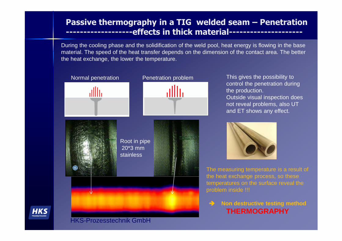
During the cooling phase and the solidification of the weld pool, heat energy is flowing in the base material. The speed of the heat transfer depends on the dimension of the contact area. The better the heat exchange, the lower the temperature.
Normal penetration This gives the possibility to control the penetration during the production. Outside visual inspection does not reveal problems, also UT and ET shows any effect.
Root in pipe20*3 mm stainless
Penetration problem
The measuring temperature is a result of the heat exchange process, so these temperatures on the surface reveal the problem inside !!!
���� Non destructive testing methodTHERMOGRAPHY
HKS-Prozesstechnik GmbH
Passive thermography in a TIG welded seam – Penetration 2-------------------effects in thick material---------------------
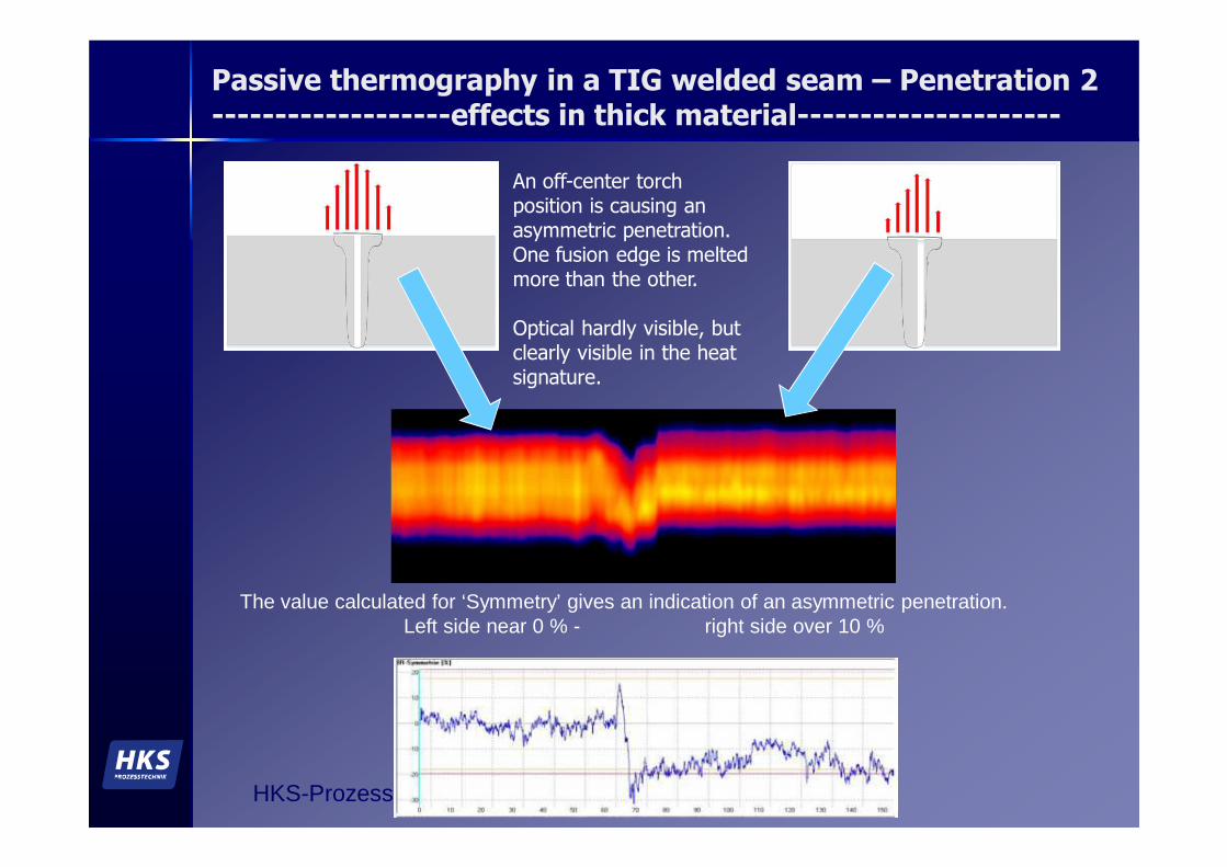
The value calculated for ‘Symmetry’ gives an indication of an asymmetric penetration.Left side near 0 % - right side over 10 %
An off-center torch position is causing an asymmetric penetration. One fusion edge is melted more than the other.
Optical hardly visible, but clearly visible in the heat signature.
HKS-Prozesstechnik GmbH
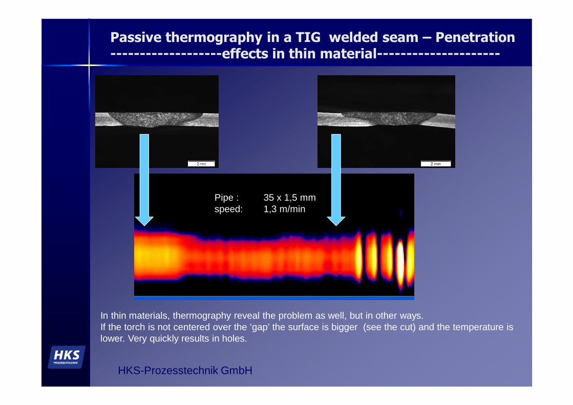
Pipe : 35 x 1,5 mmspeed: 1,3 m/min
In thin materials, thermography reveal the problem as well, but in other ways.If the torch is not centered over the ‘gap’ the surface is bigger (see the cut) and the temperature is lower. Very quickly results in holes.
Passive thermography in a TIG welded seam – Penetration-------------------effects in thin material---------------------
HKS-Prozesstechnik GmbH
Passive thermography in a High Frequency Induction pressure welding
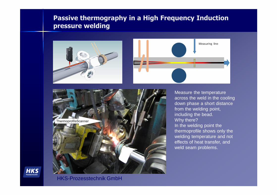
Measure the temperature across the weld in the cooling down phase a short distance from the welding point, including the bead. Why there?In the welding point the thermoprofile shows only the welding temperature and not effects of heat transfer, and weld seam problems.
HKS-Prozesstechnik GmbH
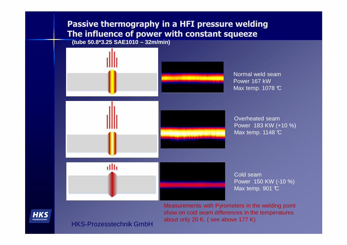
Passive thermography in a HFI pressure weldingThe influence of power with constant squeeze
(tube 50.8*3.25 SAE1010 – 32m/min)
Normal weld seamPower 167 kW Max temp. 1078 °C
Overheated seamPower 183 KW (+10 %) Max temp. 1148 °C
Cold seamPower 150 KW (-10 %) Max temp. 901 °C
Measurements with Pyrometers in the welding point show on cold seam differences in the temperatures about only 20 K. ( see above 177 K)
HKS-Prozesstechnik GmbH
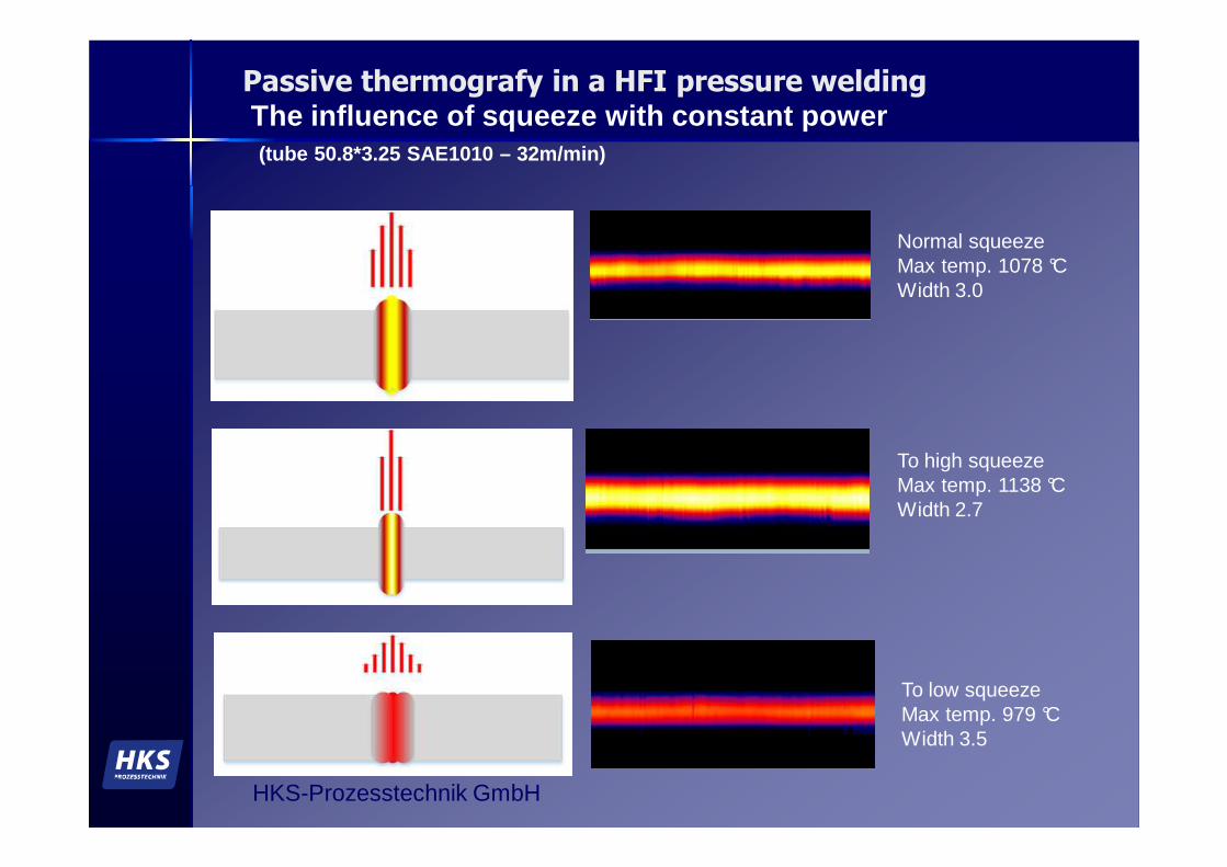
Passive thermografy in a HFI pressure weldingThe influence of squeeze with constant power(tube 50.8*3.25 SAE1010 – 32m/min)
Normal squeeze Max temp. 1078 °CWidth 3.0
To high squeeze Max temp. 1138 °CWidth 2.7
To low squeeze Max temp. 979 °CWidth 3.5
HKS-Prozesstechnik GmbH
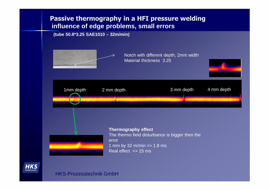
Passive thermography in a HFI pressure weldinginfluence of edge problems, small errors(tube 50.8*3.25 SAE1010 – 32m/min)
1mm depth
Notch with different depth, 2mm widthMaterial thickness 3.25
2 mm depth 3 mm depth 4 mm depth
Thermography effect The thermo field disturbance is bigger then the error1 mm by 32 m/min => 1.8 msReal effect => 15 ms
HKS-Prozesstechnik GmbH
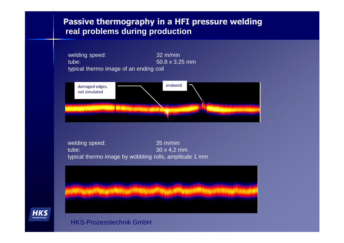
Passive thermography in a HFI pressure weldingreal problems during production
endwelddamaged edges,
not simulated
welding speed: 35 m/mintube: 30 x 4,2 mmtypical thermo image by wobbling rolls, amplitude 1 mm
welding speed: 32 m/mintube: 50.8 x 3.25 mmtypical thermo image of an ending coil
HKS-Prozesstechnik GmbH
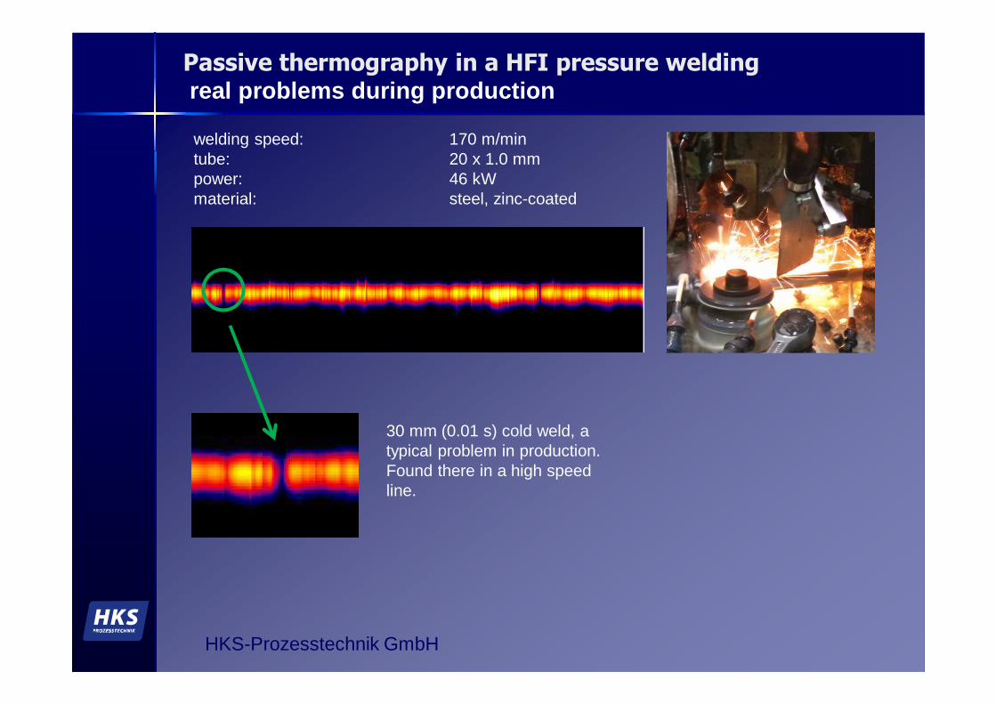
Passive thermography in a HFI pressure weldingreal problems during production
welding speed: 170 m/mintube: 20 x 1.0 mmpower: 46 kWmaterial: steel, zinc-coated
30 mm (0.01 s) cold weld, a typical problem in production.Found there in a high speed line.
HKS-Prozesstechnik GmbH
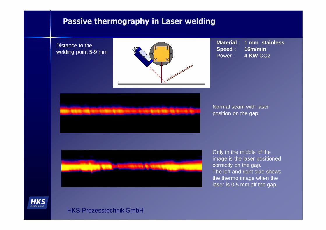
Passive thermography in Laser welding
Material : 1 mm stainless Speed : 16m/minPower : 4 KW CO2
Distance to the welding point 5-9 mm
Normal seam with laser position on the gap
Only in the middle of the image is the laser positioned correctly on the gap. The left and right side shows the thermo image when the laser is 0.5 mm off the gap.

HKS-Prozesstechnik GmbH
conclusion
� The development of passive thermography used near the welding point created the possibility to measure temperature profiles with high speed and high accuracy. To achieve that a special thermo line camera was created. The Thermoprofilescanner .
� This method is based on differences in temperatures, which occur trough differences in the heat distribution in the down cooling phase of the welding seam. This allows the possibility to see effects inside the material.
� This inline NDT process can be used in mills using TIG, Plasma, HFI and Laser welding and shows better results then eddy current and ultrasonic testing.
� This Thermography non-destructive testing method also works as a monitoring system and shows result parameters of the seam and a running thermo image. This allows tuning the machine parameters to generate continuous high quality seam.
� Over 60 applications around the world in the last three years in tube and pipe welding show the potential of this method.
� Thanks to all our costumers, that helps with theire patience and support to improve this system.


![Mighty Seam™, HFW Line Pipe (1/3) · 2019-04-08 · 2) Both weld seam and pipe body exhibit superior properties. [ I.E., lower temperature toughness and higher strain capacity ]](https://img.dokumen.tips/doc/110x75/5e6d01e9b353174159636936/mighty-seama-hfw-line-pipe-13-2019-04-08-2-both-weld-seam-and-pipe-body.jpg)