Embed Size (px)
Citation preview

C. R. GRAY Switching Systems Development
The switching systems laboratories
Of the many departmental laboratories that comprise Bell Telephone Laboratories, probably the largest are those used for dial switching tests by the Systems Development Department at West Street. Laboratories for the switching development groups must of course provide space where new telephone switching systems may be set up, tested, and studied, but such facilities by no means meet all the needs of switching develop- ment. A large amount of the work consists in modifying, improving, and supplement- ing existing systems, and most of the cir- cuits and apparatus designed for such pur- poses must be tried out with the existing circuits of the various types of switching systems. To permit this, it is necessary to have more or less permanent installations of the various switching systems now used throughout the country, complete as to Fig. 1 (at top of page) -H. T. Douglas, J. A. Mc- Hugh, and J. C. Roe check maintenance procedures on the AMA equipment.
July, 1951
variety of circuits, but of course severely skeletonized as to the normal quantities of circuits provided in a typical central office. For the large control circuits such as mark- ers, generally two or three of each system are sufficient for laboratory purposes, whereas a central office might have several times as many. For senders and similar cir- cuits more laboratory units are required since there are many varieties, and for trunks and similar circuits as many as a hundred different units for each system may be required in the laboratory.
Considerable space is obviously required to accommodate such a wide representa- tion of existing switching systems. Three entire floors in Building L and one in Build- ing K comprise the main areas, but special associated development work is carried on in seven smaller laboratories on other floors. The floor area involved is roughly 24,000 square feet. In developing new circuit ideas or for "proving -in" their switching designs
"Contents of this Issue" will be found on inside back cover
301
www.americanradiohistory.com

Fig. 2- Step -by -step system laboratory equipment in L33. In center is a typical cord and jack "patching section" for interconnection of circuits.
Fig. 3 -W. W. Connick checks wiring on the DSA board trunk circuits in the step -by -step laboratory on the third floor of Building L.
302
in an over -all system, over 200 engineers use these laboratories, many continuously, some only occasionally. The final circuit and system testing of many devices de- veloped in other departments is also done here. In appearance, circuit routines, rec- ords, wiring methods, lighting, temperature, cleaning, and dust control, these labora- tories are maintained as close to central of- fice standards as possible.
On the third floor of Building L there are two laboratories. One of them, shown in Figure 1, is an Automatic Message Account- ing center. The equipment here comprises a complete message accounting center simi- lar to those now working in Philadelphia, Newark, Chicago, and Detroit. The other laboratory on the third floor is larger and includes a variety of apparatus. In one sec- tion is a skeletonized step -by -step office with associated DSA and toll switchboard circuits, parts of which are evident in Fig- ures 2 and 3. Here also is an installation of automatic ticketing *, an early form of short - haul toll message recording applied to step -by -step offices in the Los Angeles and San Francisco areas. Also in the step -by -step area are various smaller community dial of- fices such as the Western Electric 355 -A, the Automatic Electric 35 -E -97, and 375 -B and several types of North Electric CX sys- tems, all of which appear in the field in Bell System areas, and interconnect with our standard central offices. An interesting con- trast here is afforded by a unit of old Strowger plunger -type line switches, over 40 years old, located adjacent to modern equipment. There are thousands of lines still served by these in the field, and cir- cuit questions still arise. All new PBX cir- cuit testing work is also carried on in this laboratory. Other activities in this room in- clude dial pulsing studies on all systems and ringing and tone studies. Some of the circuits and equipment for this work are shown in Figure 4.
In one section of this laboratory, life -test- ing of relays is carried on, Figure 5. Thou- sands of relays of various kinds with a number of different types of contact metals
RECORD, July 1944, page 445; October 1944, page 550.
Bell Laboratories Record
www.americanradiohistory.com

Fig. 4- Pulsing tests, tone and ringing studies, and relay tests being made in the L33 switching lab- oratory by J. Oetzman, Miss M. K. Ault, J. M. Woitovich, R. C. Townley, F. A. Bonomi, R. P. Jutson, and A. P. Goetze.
and varieties of contact protection networks have been operating here for several years in circuits so controlled that any contact failing to make or break its circuit will im- mediately indicate trouble. Forty -year trouble -free life is the goal of switching equipments. In this same area, life and circuit tests on the new 14 -type message register are in progress.
Work on the second floor is largely de- voted to toll switching. A view of this lab- oratory is shown in Figure 6. Here the crossbar toll offices, such as the No. 4, the A4A, and the 4A were developed, and test- ing of circuits for nationwide toll dialing is now being carried on.
On the first floor of Building L there are also two laboratories. In one, the No. 5 crossbar system was tested, and here studies of new features and modifications of old are still being carried on. A view down one aisle of this No. 5 crossbar laboratory is shown in Figure 7.
The other first floor laboratory of Build- ing L is largely devoted to the No. 1 cross- bar system, although the AMA equipment for No. 5 crossbar offices is also installed here. A view of the No. 1 crossbar section is shown in Figure 8.
Power for these dial switching labora- tories is furnished for the most part by storage batteries and generators located in
July, 1951
Fig. 5 -Relay contact and life test equipment in the L33 Laboratory. Thousands of relays have been tested, many for periods of several years.
303
www.americanradiohistory.com

Fig. 6 -R. J. Renahan checks wiring on toll circuits in the 2L laboratory. Here the crossbar toll offices, such as the No. 4, the A4A, and the 4A were developed. Circuits for nationwide toll dialing are now being tested in this area.
a new power room recently completed in
the basement of Building K. To permit cir-
cuits to be tested on maximum and mini-
mum voltage limits, any voltage from 14 to
58 volts is available in the various labora- tories in approximately two -volt steps. The switching facilities for this purpose in the 2L laboratory are shown in Figure 9. Pro- vision for this facility, however, means that the battery may be unevenly loaded at the tapping points, and to correct this, exten- sive switching arrangements not normally found in standard central -office power plants are required to connect the generator and regulating circuits at a number of
points on the battery. A supply for 24 -volt switchboard circuits and for tube filament supply, and several plus and minus 130 -
volt supplies from regulated tube rectifiers are also furnished. A wide variety of ring- ing voltages and tone supplies are available.
The number of portable test units, me- ters, oscilloscopes, oscillograph machines and other instruments required in these laboratories is over 1,000. Many of these devices are specialized tools for the switch- ing laboratories developed by the testing
Fig. 7 -No. 5 crossbar line -link and trunk -link frames in the L10 laboratory. ' .'-
r4, ïrr,u"-. 'jR°v `'r..!. .r.. ¶^4# r
rrr4+ey -!!.- v ' Mt* :F a' mRoäyn ; rlil1 ¡MCP PIN WR ME IN;.iWY;
a'4 ib
'fttrsr:t
www.americanradiohistory.com

engineers. Some unusual ones were recently developed by a group whose main assign- ment has been to provide more precise pulse machines, timers, photocell probes, etc., for electromechanical studies of relays and switches and for investigating contact and circuit phenomena.
Air conditioning, with temperature and humidity control, is provided for Building L. The machinery is on the roof of Building L and includes an electrostatic precipitator to augment the usual glass wool and paper air filters. Even with this auto- matic air cleaning, however, routine pres- sure cleaning of the relays and switches in these areas is done regularly. For this pur- pose, the standard central -office procedure is used which requires large exhaust fans connected to dust -tight cloth tents erected around the frames, and air gun pressurized cleaning of the frames, top to bottom and front and rear. Because of the much higher concentration of personnel and wiring ac- tivity in these laboratories, this has to be done more often than in a working central office, two to four times a year being the average for the laboratory frames depend- ing upon the amount of activity in the im- mediate area.
Because of the frequent need to vary the association of circuits within a laboratory and to connect with those in another, exten- sive distributing and patching facilities are required in each laboratory. A typical patching panel is evident near the middle of Figure 2.
Each new system developed, and each change in traffic conditions or new require- ment arising, all add new problems for the Laboratories testing group. In a typical three -month period over 40 new circuits were developed and over 500 others were revised to meet new conditions. Not all of these required laboratory testing but the number is indicative of the activity in- volved. Although in this systems labora- tory, new circuits are tested to make sure they will perform their functions properly, this is often the shortest part of the job. The most difficult and time -consuming work is in analyzing the equipments to de- termine their weaknesses. The goal behind all of this laboratory effort is to give the
July, 1951
Fig. 8 -W. H. Berck, P. R. Brockett, and R. I. Nolan work on the tandem and No. 1 crossbar laboratory equipment in L13.
Fig. 9- Typical laboratory power distribution switch- board for the systems switching laboratory.
www.americanradiohistory.com

THE AUTHOR: Joining the Engineering De- partment of the Western Electric Company in 1923, C. R. GRAY was assigned to the switching systems Development group where he was engaged in design, testing, and field trial work on step -by -step, PBX and community dial office circuits, up to the be- ginning of World War II. During the war he traveled to England, Africa, and Italy on Signal Corps work that is still rated "Secret." Near the end of the war he was assigned to Navy radar work at Whippany. After the war he was engaged in No. 5 crossbar circuit development work, and was one of the resident engineers at the Media, Pa., trial for about nine months. He then was placed in charge of the laboratories facilities groups for the Switch- ing Systems Department. In April of this year he transferred to a group at Murray Hill working on military projects.
telephone subscriber the best possible serv- ice. Before a circuit is given a clean bill of health by the testing staff, therefore, the circuit must be tested under adverse condi- tions, including voltage and resistance vari- ations, cable and line changes, etc. The
effects of subscriber and operator errors and habits in dialing and keying are also taken into consideration. Only after a cir- cuit has performed satisfactorily under these and many other adverse conditions is it given final approval.
Computer for Guided Missiles The guided missile shown on the front
cover travels at supersonic speeds under control of a complex but accurate electronic
306
control system. This system, developed by the Laboratories, computes where the powerful missile should meet high -flying enemy aircraft, guides it to that point and then explodes it.
This project is part of a contract between Western Electric and the Army Ordnance Corps. Aerodynamics and design of the mis- sile itself are being handled by the Douglas Aircraft Company, Inc., as a sub -contractor.
Enemy aircraft are detected and tracked by Laboratories -Western Electric radar, which feeds the computer of the control sys- tem information concerning the plane's alti- tude, speed, and course.
Launching and flight of the new anti -aircraft missile, which travels at supersonic speeds, are controlled from this master panel. (This photo- graph and the one on the cover were approved for publication by the Department of Defense.)
Bell Laboratories Record
www.americanradiohistory.com

Mechanically
wrapped
connections H. A. MILOCHE Switching Systems Development
Building and maintaining the great quan- tities of telephone equipment in the Bell System requires that hundreds of millions of wired connections be made annually. What might otherwise be considered a minor op- eration assumes major importance because of the number of times it must be performed.
There are several general types of termi- nals to which connections are made. A con- ventional one is a sheet metal strip with a hole punched near the end; the wire is threaded into the hole, looped tightly, and soldered. A second type has notches near the end instead of a hole; the wire is
(a) (b)
(C) Fig. 1 -The muzzle of the wrapping tool and the way it makes the wrapped connection.
Using the Laboratories' electrically -operated wrap- ping tool, Frank Reck is making a connection to a terminal.
wrapped around the notches and soldered. In another type, the terminal is a round wire and, while not extensively used in terminal design, the established practice has been to form a hook in this wire, loop the connect- ing wire around the hook, and solder it.
The trend in design is to make apparatus smaller, increasing the use of thin, narrow strips and round wires instead of the usual flat punched strips for terminals. This intro- duces the problem of how best to make con- nections to them. The acceptability of ap- paratus employing such assemblies depends in part on the possibility of economically connecting hook -up wiring to the apparatus.
In considering the use of round -wire ter- minals in large numbers a manual method of connecting would involve either the con- ventional method of forming a hook in the terminal into which the connecting wire could be looped, or forming the wire around the terminal. Either method could be employed only where the terminals have sufficient rigidity to withstand the lateral stresses involved. The lighter terminals an- ticipated in new apparatus will not have sufficient rigidity. Reinforcement is unde- sirable from an economic standpoint. It thus becomes evident that a requirement of the connecting method would be that it provide temporary support for the terminal.
Study of the problem has resulted in the development of a new method of fastening wires to various types of terminals. Instead
July, 1951 307
www.americanradiohistory.com

Fig. 2 (left) -The original wrapping tool was a simple rod with two holes in the end. Fig. 3 (right) -A pan of pliers was modified to make a wrapping tool.
of the wireman inserting the wire into a hole, notch, or hook, he uses a special "pistol" type tool that wraps the wire around the terminal in a series of convolutions. The tool as originally developed was applicable to making wrapped connections on round or very narrow square or rectangular cross -sectioned terminals only. The Western Electric Company developed an adaptation of the wrapping tool suitable for use on the standard approximately 3 ' wide terminals generally used on apparatus such as relays, crossbar switches and terminal strips.
The wrapping end of one of the early tools is shown in Figure la. It consists es- sentially of a rotatable spindle housed in a stationary sleeve. To make a connection, the bare end of the connecting wire is inserted into the groove 1 in the spindle, and an- chored in the notch 2 in the housing by the operator, who holds the insulated connect- ing wire against the housing. Then the spin-
dle is placed on the terminal so that the terminal enters the hole 3; the spindle is ro- tated, wrapping the connecting wire around the terminal as shown in Figure lb, produc- ing a connection illustrated by Figure lc. As the spindle rotates, a longitudinal stress is developed in the wire but since the wire is anchored at the notch, it is free to move only at the bare end. The wire is thus drawn out of the slot to form a helix on the terminal.
The number of convolutions in the helix is determined by the length of the bare wire inserted in the slot of the tool. As the spin- dle turns, a helix is formed on the terminal until the bare wire in the slot is exhausted. When the end emerges from the slot, the tip extends from the helix, as shown in Figure lc. It is necessary that this tail be short to avoid contact with adjacent terminals in congested areas. The length of the tail is
determined by the distance between the slot
Fig. 4 (left) -The first hand- operated pistol type tool. Fig. 5 (right) -The Laboratories model of an electri- cally driven wrapping tool.
308 Bell Laboratories Record
www.americanradiohistory.com

and the terminal hole in the spindle, and, in the case of a rectangular terminal, by the position of the slot at the moment the end of the wire emerges from it.
Rotation of the spindle can be accom- plished by several means. The original tool, Figure 2, was simply a short rod having a central hole for a terminal and a hole ad- jacent to it into which the bare end of the connecting wire could be inserted while the operator held the insulated portion. Ro-
toward producing an electrically operated tool; a model of this is illustrated by Figure 5. Pressure on the trigger closes a switch that starts the motor, driving the spindle until the trigger is released. This tool is pro- vided with a mechanism insuring that it stop only in the normal loading position.
Development of a power operated tool was also carried on simultaneously by West- ern Electric engineers. In the Hawthorne factory, since many of the screwdrivers,
Fig. 6 (left)-Western Electric (Hawthorne) model of an air operated tool. Fig. 7 (right) -Western Electric (Kearny) model of an electrically operated tool.
tating the spindle with the fingers produced the helix of connecting wire on the terminal.
With this basic idea, the development of a satisfactory tool became a problem of how best to produce the rotary motion. One way of doing this is illustrated by Figure 3, in which the rotary motion is supplied by a plier type action, using a slightly curved rack to rotate an associated pinion. Figure 4 shows an early model of a hand -operated "pistol" type tool, developed by a group in the Switching Apparatus Development De- partment under the supervision of C. N. Hickman and R. F. Mallina, where spindle rotation is produced by the same type of rack and pinion structure. After the wrap is made, a restoring spring returns the spindle to its normal position.
Because of the many connections that an operator may make in a day, use of elec- trical or air power is desirable to eliminate fatigue and to promote uniformity and speed. Development work was continued
July, 1951
wrenches and other tools are operated by air, the use of this type of power for operat- ing a wrapping tool was investigated. Mem- bers of the Engineer of Manufacture Or- ganization under E. J. Beaulieu carried on a study that resulted in a piston type spindle drive, Figure 6, also having rack and pinion driving and restoring means.
In the Kearny Works, the Western Elec- tric engineers under N. N. Babcock studied the use of commercial electric power for rotation in developing the tool shown in Figure 7. This tool has a multiplicity of wire slots in the rotating spindle, eliminating the need for a positive stop or restoring mecha- nism. Having a number of wire slots makes it easy to find a slot for inserting the con- necting wire.
In both the Hawthorne and Kearny de- velopments, a slotted stationary central shaft was substituted for the round terminal hole in the spindle; the diameter of this central shaft is slightly greater than the width of the
309
www.americanradiohistory.com

Fig. 8 -The rectangular slot in the end of the Hawthorne wrapping tool prevents twisting of the terminal under the wrapping torque.
spring terminal to which connection is to be made. The slot in the end of the shaft ac- cepts the terminal and prevents twisting of the terminal under the wrapping torque. Figure 8 shows the slot in the end of the Hawthorne wrapping tool. At the present time, these tools are being made up in small lots for use within the Bell System only.
In addition to the electrically and pneu- matically driven tools, an improved hand - operated tool has been developed princi- pally for maintenance purposes. The main- tenance tool design group under V. F. Miller in the Switching Apparatus Development Department, has produced a lightweight,
easily operated tool similar to the original hand -operated tool. This tool, shown in Fig- ure 9, is provided with a fixed stop for a
given number of turns of the connecting wire, and a restoring spring to return the spindle to its normal loading position.
Experience has shown that the loading, positioning, and connecting operations can be performed in considerably less time than methods used heretofore. The connection is
better because it is mechanically secure, an advantage conducive to good soldering. A
very important advantage is that it elimi- nates clipped wire ends that frequently fly
into the maze of wires surrounding a con-
Fig. 9 -The hand- operated tool.
THE AUTHOR: Equipment engineering has School. While attending Cooper Union at night, he
occupied H. A. Miloche's time ever since he grad- worked by day for a company engaged in building uated from New York City's Stuyvesant High motor controls. Following his graduation with a
B.S. in M.E. degree in 1923, he came to the Labo- ratories, and has since been active in some phase of
equipment engineering for telephone systems. In this field, he has worked on toll switchboards, cur- rent engineering on local and toll manual, panel, and step -by -step offices, and for several years was in charge of a group handling this work. Subse- quently, he did equipment development on such items as teletype switching, telegraph, crossbar, and automatic message accounting. During World War II he contributed to the design of fire control and bombing radar equipment. More recently, his
activities have involved machine announcing sys-
tems, multi- frequency signaling, and wiring problems.
310 Bell Laboratories Record
www.americanradiohistory.com

rection and later may become sources of short circuits or grounds.
Formation of a helical coil on a mandrel is a familiar operation in the manufacture of springs. It involves anchorage of the wire to a rotating part and rotation of the mandrel. The wrapping tool inverts the spring wind-
ing process, providing a rotating wire feed revolving on a stationary terminal.
Results are particularly gratifying in that wrapping tools not only provide an excellent mechanical connection at low cost, but also make it possible for the terminal to be in its simplest and most inexpensive form.
Diesel Engine Sets for Radio Relay The TD -2 radio relay stations at Barro
and Cedar Mountain, Utah, and Wendover, Nevada, are too remote to connect to com- mercial power lines, and power must be generated at the stations. This will be done by two diesel engine driven alternator sets, one of which carries the load while the other acts as a standby. To equalize wear, auto- matic control equipment interchanges the
Diesel engine sets and control unit being tested ment to the repeater stations.
regular and standby set every twelve hours. The automatic control equipment was de- signed by V. T. Callahan and L. D. Fry of the Laboratories and manufactured by Western Electric. The diesel engine alter- nator sets were manufactured by Hercules Motors Corporation and were a result of collaboration by Mr. Callahan and engi- neers of Hercules, and General Electric.
at the Hercules plant, Canton, Ohio, before ship-
July, 1951 311
www.americanradiohistory.com

The radar range calculator
Like a telescope, a radar system has a man's eye at one end and a distant object at the other, and the distance one can see depends on the sensitivity of the device and the size of the object observed. The calcula- tion of effective radar ranges, however, is an involved computation requiring the evalua- tion of a mathematical expression with seven variables. Such calculations had to be made with discouraging frequency while the Lab- oratories was intensively engaged in radar development during World War II. To save much of this time and labor, S. C. Hight designed the radar range calculator shown on the opposite page. It proved so useful that in 1945 it was issued as a classified document for the Navy, but has recently been unclassified by the government.
The expression for the effective distance that a radar can see is:
D / f \12 ¡ tPC2xZC \4 `1640 J l(47r)3 icrN
Here x and T are constants, but the remain- ing seven parameters -f, t, P, N, c, X, and !- may have different values for each radar equipment or situation. The calculator pro- vides six concentric disks of increasing diam- eter on which are marked the range of values these various parameters may take. These disks are pivoted so that they may be rotated to bring any particular value of the parame- ter opposite an index pointer on the next larger disk. Values for the 7th parameter, sigma, which represents target size, are marked beneath the disks on the card on which the disks are mounted. As the final step in setting up a problem, a transparent rotatable arm with a central hair line is moved to the value of sigma, and under this line on the inner, or smallest disk, is read the desired value of the distance D.
A determination of distance is begun by first setting the value of f opposite the in- dex mark at the top of the base card; f rep- resents the pulse repetition rate, or the num-
312
ber of pulses per second sent out by the radar transmitter. Following this, the value of t on the next disk is set opposite the index on the f disks; t is the duration of each pulse, and is given in microseconds. In a similar manner the value of P, the pulse power, is set opposite the index on the t disk; the value of N, receiver noise, is set to an index on the P disk the value of c, antenna gain, is set to an index on the N disk; and the value of X, the wavelength, is set opposite the index on the G disk. After making these set- tings, the arm is moved until the hair line is over the proper value of sigma, and then the value of D is read under the hair line on the inner scale of the lambda disk.
The parameter sigma represents the "ra- dar cross -section" of the reflecting object, and is numerically equal to the cross -sec- tional area of a metal sphere that, if sub- stituted in place of the target, would return the same echo power. For most types of tar- get, however, the value of sigma varies somewhat with the wavelength, and thus to set the arm on the proper value, one would have to know the value of sigma for the target and wavelength concerned. To supply this information in convenient form, the graph below the sigma scale has been provided. Lines for typical common targets are drawn on this graph in such a way that when the hair line on the arm is set on the point where the target line intersects the value of wavelength used, the proper value of sigma will appear under the hair line. Thus when this lower graph is used, the sigma scale may be ignored. The data used in plotting this lower graph represent sta- tistical averages of experimental results ob- tained under operating conditions, and are sufficiently precise for ordinary work.
This calculator is useful not only in solv- ing for distance for specific radar equip- ments, but for studying the effects of the various parameters on distance. In the ac- companying illustration, the calculator is
Bell Laboratories Record
www.americanradiohistory.com

set for f = 1kc,t= 1v.'s,i' = 10 kw, N = 14db,c =25db, and X= 10 cm, and a destroyer as target, and the distance is found to be 50 miles. Had the pulse power been only one kilowatt, while the other parameters remain the same, the distance
a
K
would be found to be only 28 miles, while had the pulse power been increased to 100 kw, the distance would have been increased to 89 miles. It is in giving information of this sort that the calculator is particularly useful.
RADAR RANGE CALCULATOR
START
01
N`,1 w OxCYCLE3 PER SECgy ,` 00 , i I I O
,,.11° ' ,11/1
E OS °00 ó`p`\ SF-C ., ,,,, . ,c.,- , , r+ *Kw 'I ,, \ ` it ., , T PuLSF *w'
. 11 ,I,,,,,,, .0,,,,00y
PE. \ ' "
.`"v` iossce) , ° '4 ` P +` ,
N OE yr, . , , \ s,, \ o i , <J
Vy' le `\ , . pt.r0
vnr lolstl) N / . r ,,.
CC \.°. : . LENGTH r g` \.c ' l \ si rf \ y6
_
ÿù
_ Z ÿ t6 ¢
gis
=
) pD -
-
.C6 WY 1010° SIGMA
S
July, 1951
T,RCET
Fp° Wc+O NCE
Si2ES AVERAGED FROM FIELD
EANE
INSTRUCTIONS
TURN EACH DISK UNTIL PROPER VALUE IS OPPOSITE INDEX ON NEXT LARGER DISK. SET RADIAL ARM TO APPROPRIATE TARGET
SIZE (EITHER ON THE GRAPH OR THE NUMERICAL SCALE) AND READ RANGE.
4
46
313
www.americanradiohistory.com

Terminals for the TD -2
radio relay system
Before the end of this year, the TD -2
radio relay system* will span the country
from New York to the Pacific Coast. Al-
though its full capacity is not used at the
present time, it is capable of providing six
broadband channels in each direction, and
each channel may carry a television pro-
gram or hundreds of telephone conversa-
tions. The frequency -modulated signals
beamed from tower to tower at about 25-
mile intervals are in the frequency band between 3700 and 4200 megacycles, but at each repeater station the mid -band fre-
quency of each channel is reduced to 70 mc
for amplification. Where it is necessary to
connect to branch TD -2 systems, or where for operating reasons it may be necessary to switch between channels, the interme-
diate frequency circuit for each channel is
carried through a monitoring and patching bay between the radio receiver and the ra-
dio transmitter, and the switching is done
at 70 mc. Where it is necessary, on the
other hand, to tie in with some other type of transmission system, an FM terminal is
used to convert between the 70 -mc fre-
quency- modulated signals and the video
or multi -channel telephone signals. Although these FM terminals are de-
signed to handle both television and multi-
channel telephone signals, the two types of
signals differ so basically that modifica-
tion in the operation of some of the terminal circuits is required to transmit the two types of signals. Such circuit changes are controlled by knobs and switches so that the changeover may be accomplished in a
matter of seconds. This difference in the two types of trans-
mitted signals is indicated in Figure 1,
which is a plot of the frequency excursion of the system at IF for the two types of sig-
* RECORD, October 1950, page 442.
J. B. MAGGIO Transmission Development
Three FM terminals in the Long Lines build- ing. In the two lower terminals, the lower unit is the FM receiver, while the three units above it comprise the FM transmitter.
314 Bell Laboratories Record
www.americanradiohistory.com

66MC --
'0 MC
'4 MC- - - -
TELEVISION s-MULTIPLEX TELEPHONE-'
Fig. 1- Representative frequency excursion plot for television transmission, at left, and multi- channel telephone transmission, at right.
nais. For multiplex telephony, the fre- quency deviation is centered about the middle of the IF band, and the average output frequency is 70 mc. For television signals, on the other hand, the frequency deviation is unidirectional downward from the tips of the synchronizing pulses at 74 mc, and the average output frequency may vary quite widely with the content of the television picture being transmitted. In this diagram, the television wave form is drawn in the conventional polarity, and hence the frequency scale appears inverted, with the lowest frequency, which represents white in the picture, at the top on the diagram, and the higher frequencies, representing the darker portions of the picture, below them. The maximum frequency, which is that of the synchronizing pulses, is thus at the bottom of the diagram.
In the FM terminal transmitter, fre- quency modulation is accomplished by vary- ing the repeller potential of a Western Electric reflex oscillator* operating at 4280 mc. Figure 2 is a plot of the output and frequency of a typical tube as the repeller voltage is varied. When the tube is op- erated into a matched impedance, the volt- age- frequency characteristic approximates that of a cubic equation. Such operation would give excessive nonlinearity, and would result in intolerable crosstalk be- tween telephone channels. By optimizing the load impedance, however, it is possible to produce a frequency -voltage relation that is highly linear over the required range
° RECORD, August 1945, page 287.
July, 1951
as indicated by the dashed curve, Figure 2. To produce the desired 70 -mc output,
the 4280 -mc frequency -modulated signal is mixed with the output of a second reflex oscillator operating at 70 mc below the mean frequency of the deviated oscillator. This second oscillator is not frequéncy- modulated by the telephone or television signals, but its frequency is controlled by an automatic circuit to maintain the de- sired 70 -mc difference despite drifts in the output frequency of the deviated oscillator. The combined output is rectified in a sili-
4280 MC
/ / /
/ /
/ i MATCHED IMPEDANCE
/ -- OPTIMIZED IMPEDANCE
REPELLER VOLTAGE
Fig. 2- Curves of output and frequency as the repeller voltage of a Western Electric 4280 -mc reflex oscillator is varied.
con crystal converter unit where the dif- ference frequency, centered about 70 mc, is the useful product of the modulation by the non- linear crystal.
A block diagram of a complete FM trans- mitter is shown in Figure 3. The television or telephone multiplex signal must first be am- plified to the proper level to modulate the reflex oscillator. This is accomplished by a video amplifier employing negative feed- back. A gain control ahead of the ampli- fier enables the terminal to accommodate a range of input signal levels. For televi- sion operation a clamping circuit is in- serted between the video amplifier output
315
www.americanradiohistory.com

TELEVISION OR %HAMPLIFIER TELEPHONE GAIN INPUT CONTROL
VIDEO
TEL
TVp CLAMPING
CIRCUIT
FM --'1" LIMITER - GENERATOR AMPLIFIER
AUTOMATIC FREQUENCY
"4"-. CONTROL
TO RADIO EQUIPMENT
and the FM generator to restore each syn-
chronizing pulse to a pre -determined value of voltage. Since the repeller voltage and the frequency are related, as shown in Fig- ure 2, the clamping action insures con-
stancy of the frequency during the tips of
the synchronizing pulses regardless of the content of the television picture.
As indicated in the lower diagram of
Figure 2, the power output of the reflex oscillator varies as it is frequency -modu- lated. To remove this amplitude modula- tion, a limiter -amplifier is employed. This amplifier provides gain and insures a con- stant power output by the use of a silicon crystal instantaneous amplitude limiting circuit. Additional outputs are also pro- vided for monitoring the IF output of the terminal and for the operation of the auto- matic frequency control circuit. This latter circuit does not operate the same for tele- vision as it does for multi- channel tele- phone transmission. For television transmis- sion, the circuit measures the frequency at the limiter -amplifier output only during the time of the synchronizing pulses of the television signal, and controls the fre- quency of the beating oscillator in the FM generator so that this frequency is main-
Fig. 3 - Block dia- gram of the FM transmitter.
tained at 74 mc. The frequency control is
enabled by gating pulses supplied from the clamping circuit, which occur simultane- ously with the synchronizing pulses of the television signal being transmitted. In the absence of an input signal to the terminal, the pulses continue at a slightly lower repe- tition rate so that automatic frequency con- trol is not lost. For telephone transmission, on the other hand, the automatic frequency control circuit measures the average fre- quency at the output of the limiter -ampli- fier, and varies the frequency of the beating oscillator to maintain the average output frequency at 70 mc.
Physically, the FM terminal transmitter occupies 32 inches of vertical space on a standard 19 -inch duct type framework, as shown in the illustration on the first page of this article. It consists of three rack -mounted units: the FM generator, the video ampli- fier including the clamping circuit, and the control unit on which are mounted the limiter -amplifier and the automatic fre- quency control unit subassemblies. The unit is powered by the TD -2 system -11 -, + 130 -, and + 250 -volt power plants. Con- tinuous meter indication is given of the out- put of the FM generator and of the opera-
70 MC INPUT
AMPLITUDE LIMITER
TELEVISION o OR
TELEPHONE o OUTPUT
-- DISCRIMINATOR - DETECTOR - -- BALANCED VIDEO AMPLIFIER - --
Fig. 4- Simplified schematic of the FM terminal receiver.
316 Bell Laboratories Record
www.americanradiohistory.com
tion of the amplitude limiter. In addition, a third meter is provided which together with a switching system enables the space currents of most of the vacuum tubes in the terminal transmitter to be measured at nor- mal and reduced heater power for in -serv- ice filament activity tests.
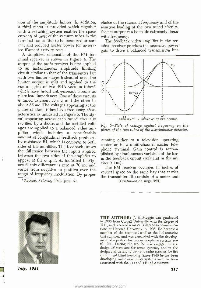
A simplified schematic of the FM ter- minal receiver is shown in Figure 4. The output of the radio receiver is first applied to an instantaneous amplitude limiting circuit similar to that of the transmitter but with two limiter stages instead of one. The limiter output is split and applied to the control grids of two 404A vacuum tubes° which have broad anti- resonant circuits as plate load impedances. One of these circuits is tuned to about 55 mc, and the other to about 85 mc. The voltages appearing at the plates of these tubes have frequency char- acteristics as indicated in Figure 5. The sig- nal appearing across each tuned circuit is rectified by a diode, and the rectified volt- ages are applied to a balanced video am- plifier which includes a considerable amount of longitudinal feedback produced by resistance Rl, which is common to both sides of the amplifier. The feedback causes the difference between the inputs applied between the two sides of the amplifier to appear at the output. As indicated in Fig- ure 6, this difference is zero at 70 mc and varies from negative to positive over the range of frequency modulation. By proper
° RECORD, February 1949, page 59.
July, 1951
choice of the resonant frequency and of the resistive loading of the two tuned circuits, the net output can be made extremely linear with frequency.
The feedback video amplifier in the ter- minal receiver provides the necessary power gain to drive a balanced transmission line
55 70 85 FREQUENCY IN MEGACYCLES PER SECOND
Fig. 5 -Plots of voltage against frequency on the plates of the two tubes of the discriminator detector.
running either to a television operating center or to a multi- channel carrier tele- phone terminal. Gain control is accom- plished by simultaneous variation of the loss in the feedback circuit (R2) and in the mu circuit (R3) .
The FM receiver occupies 14 inches of vertical space on the same bay that carries the transmitter. It consists of a meter and
(Continued on page 323 )
THE AUTHOR: J. B. Maggio was graduated in 1935 from Cornell University with the degree of E.E., and received a master's degree in communica- tions at Harvard University in 1936. He became a member of the technical staff at the Laboratories that summer, and was associated with the develop- ment of repeaters for carrier telephone systems un- til 1940. During the war he was engaged in the design of receivers for sonar systems, and in the design and testing of airborne radar systems for fire control and blind bombing. Since 1940 he has been developing microwave relay systems and has been associated with the TD and TE radio systems.
317
www.americanradiohistory.com

Historic firsts: Radio - controlled airplane
The guided missile which furnished this month's cover and is described on page 306 brings to mind an early venture of the Laboratories into the same general field in 1918. Since then, target planes have been controlled by radio, and such drone planes have also been used to gather data in the vicinity of atomic explosions. Guided missiles, in the form of aerial bombs, have been directed to their waterborne targets by radio from distant planes. The first achievement of the radio control of one air- plane by another, however, goes back to 1918, and was largely the work of A. A. Oswald of these Laboratories, at that time the Engineering Department of the Western Electric Company.
The desirability of a remote control plane became evident during World War I, and by 1917, stimulated by the successful demon- stration of two -way radio telephone com- munication between plane and ground*, the Signal Corps had become much inter- ested in obtaining the necessary circuits and apparatus. At that time several "stabilizers" - automatic pilots they would now be called - were available that would hold a plane on a set course. What was needed was radio
* RECORD, January 1944, page 221.
equipment that could send signals to the drone plane to adjust the course the stabi- lizer was following so as to guide the plane on the desired course. Satisfactory radio telephone equipment for two -way com- munication between plane and ground had already been built by the Western Electric Company, and at the request of the Signal Corps, they undertook to supply suitable radio equipment for the remote control of a plane. A. A. Oswald of the Research De- partment was assigned to the job.
In cooperation with the Signal Corps and the manufacturers of the stabilizer, and using originally the equipment developed for radio telephone communication with planes, Oswald carried out preliminary tests, with signals transmitted only in one direc- tion, in January 1918. It at once became evident that interlocked return radio signals would be needed to avoid interference and to insure quick and reliable action. The necessary equipment was developed, and by September of that year it had been installed in a drone and in a master plane.
The first successful test flight was made at Langley Field, Va. on September 16, 1918. Oswald rode in the drone along with the pilot, Lieutenant Brooks. Arrangements had
(Continued on page 328)
318 Bell Laboratories Record
www.americanradiohistory.com
Single-frequency
signaling system
Signaling arrangements planned for the nationwide operator toll dialing network must be capable of transmission not only of the called subscriber's number, but also of various supervisory signals, all of them on a transcontinental basis. Some supervisory signals are required in establishing the con- nection, and in releasing it at the end of the conversation. Other supervisory signals are required to indicate such things as a called subscriber's line busy. Preferably, all trans- mission should be confined to the same pair of wires or to the same channel used to transmit speech.
The present standard CX signaling sys- tem ° which operates over a direct current channel derived by compositing a voice telephone circuit, is capable of transmitting both the called subscriber's number and all supervisory signals but, because of low transmission speed, the maximum range of the system is limited to 250 miles. Where speech uses a channel of a carrier system, the signaling channel is separate from the speech channel. In addition, the voice fre- quency toll circuit required for compositing may not be available, because there are usually far fewer CX signaling paths than voice channels. A separate carrier telegraph system is capable of transmitting both the subscriber's number and all supervisory sig- nals, but this system definitely requires separate signaling and speech channels. The present "multi- frequency signaling sys- tem"f designed especially for crossbar of- fices, is capable of quickly transmitting the called subscriber's number over the speech channel, but this system does not take care of supervisory signals.
A signal frequency signaling system has been designed to meet all the signaling re-
= RECORD, October, 1947, page 370. f RECORD, December, 1945, page 466.
July, 1951
C. W. LUCEK Switching Development
quirements of the nationwide operator dial- ing network. In areas where multi -fre- quency signaling is not used, it provides for transmission of the called subscriber's num- ber as well as all supervisory signals. In areas where multi- frequency is used to transmit the called subscriber's number, the single frequency signaling system provides for only supervisory signals. The desira- bility of the new system has been recog- nized for some time and it is the result of work carried on by various members of the switching development group during the past decade.
Basically, all signals required in the op- erator dialing network are composed of "on- hook" or "off- hook" signals. These primary signals, as the name implies, are similar to those created when the handset of the sub- scriber's instrument is "on" or "off" its cradle or "hook." Some of the signals are a repetitive series of "on- hook" or "off - hook" signals distinguishable from one an- other by duration or by the patterns of repetition. If, therefore, signal tone some- where in the voice frequency bandwidth is sent over the toll line to represent an "on- hook" signal, and no tone transmitted to represent an "off- hook" signal, a system can be established capable of transmitting both the called subscriber's number and super- vision over any distance that speech can be sent, and with equal speed of transmission. In essence, this is exactly the solution of- fered by the single -frequency system.
The choice of not transmitting a tone to indicate an "off- hook" signal eliminates un- desirable signal tone during the conversa- tion period of the call, at which time the off -hook condition exists at both ends of the circuit. During the waiting period before the called subscriber answers when an on- hook condition exists at the called end, a network in the signaling circuit, having a
319
www.americanradiohistory.com

TRANSMITTER
TRANSMITTING
R
vw
M (ORDER) LEAD
SIGNAL SOURCE
J
J
(B)
--
E (RECEPTOR)
LEAD
S.F. SIGNALLING CIRCUIT
BAND FILTER (A)
RECEIVER
D-C
NETWORKS
ANTI- RESONANT
RESONANT
L LOW -PASS
FILTER !\V LIM ITER
RELAY CONTROL CIRCUIT
L L J J
Fig. 1 -Block diagram of single- frequency signaling circuit for use on four -wire toll lines.
T
RECEIVING
loss at the signal tone frequency, is intro- duced into the talking path. Though the calling subscriber can hear this tone, its level is 55 db below normal voice level and therefore not objectionable. It was found advisable from a circuit standpoint, to transmit tone for both the duration of the on -hook signal and the idle condition of the toll circuit. In order not to overload toll line repeaters, however, when all channels of a carrier system are in the idle condition and all therefore carrying continuous tone, the signal tone sent over the toll line is lowered to 20 db below normal voice. This low level of tone requires that the receiver detecting it must have a high sensitivity.
The single- frequency signaling circuit is composed essentially of a transmitter and a receiver, together with the necessary con- trol circuits, as shown in the block diagram of Figure 1. There is also included in the receiving channel a network A to prevent
320
the signal tone from disturbing the sub- scriber and a voice amplifier B which acts both as a one way transmission device and as a means to compensate for the bridging loss of the receiver. This terminal circuit is
designed to transmit a 1600 -cycle tone over one side of a four -wire circuit, while its receiver detects the 1600 -cycle tone sent from the distant end.
For two -wire toll lines, transmission and reception must be over the same wires; this requires modifications in the terminal equipment to provide the equivalent of the four -wire system. In this case, 1600 -cycle tone is sent in one direction and 2000 -cycle tone in the other -a measure which greatly facilitates the elimination of difficulties with returning echoes. The receiver at each end is designed to receive the particular fre- quency sent from the distant end. Figure 2
shows the additional equipment that must be added to the transmitter and receiver
Bell Laboratories Record
www.americanradiohistory.com
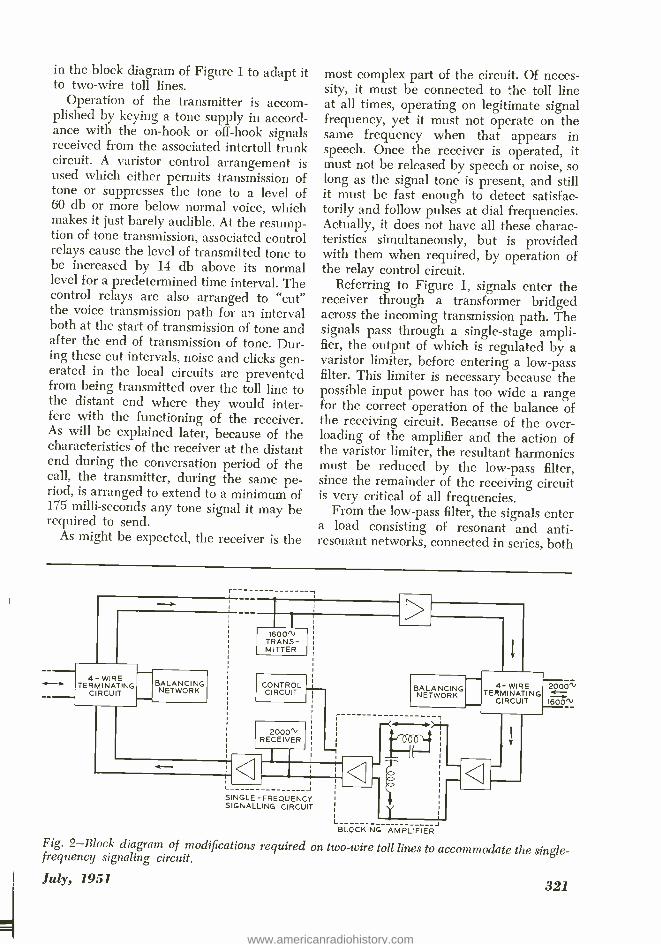
in the block diagram of Figure 1 to adapt it to two -wire toll lines.
Operation of the transmitter is accom- plished by keying a tone supply in accord- ance with the on -hook or off -hook signals received from the associated intertoll trunk circuit. A varistor control arrangement is used which either permits transmission of tone or suppresses the tone to a level of 60 db or more below normal voice, which makes it just barely audible. At the resump- tion of tone transmission, associated control relays cause the level of transmitted tone to be increased by 14 db above its normal level for a predetermined time interval. The control relays are also arranged to "cut" the voice transmission path for an interval both at the start of transmission of tone and after the end of transmission of tone. Dur- ing these cut intervals, noise and clicks gen- erated in the local circuits are prevented from being transmitted over the toll line to the distant end where they would inter- fere with the functioning of the receiver. As will be explained later, because of the characteristics of the receiver at the distant end during the conversation period of the call, the transmitter, during the same pe- riod, is arranged to extend to a minimum of 175 milli- seconds any tone signal it may be required to send.
As might be expected, the receiver is the
most complex part of the circuit. Of neces- sity, it must be connected to the toll line at all times, operating on legitimate signal frequency, yet it must not operate on the same frequency when that appears in speech. Once the receiver is operated, it must not be released by speech or noise, so long as the signal tone is present, and still it must be fast enough to detect satisfac- torily and follow pulses at dial frequencies. Actually, it does not have all these charac- teristics simultaneously, but is provided with them when required, by operation of the relay control circuit.
Referring to Figure 1, signals enter the receiver through a transformer bridged across the incoming transmission path. The signals pass through a single -stage ampli- fier, the output of which is regulated by a varistor limiter, before entering a low -pass filter. This limiter is necessary because the possible input power has too wide a range for the correct operation of the balance of the receiving circuit. Because of the over- loading of the amplifier and the action of the varistor limiter, the resultant harmonics must be reduced by the low -pass filter, since the remainder of the receiving circuit is very critical of all frequencies.
From the low -pass filter, the signals enter a load consisting of resonant and anti- resonant networks, connected in series, both
4- WIRE TERMINATING
C RCU T
BALANCING NETWORK
6m.
1
1600" TRANS- MITTER
CONTROL CIRCUIT
2000" RECEIVER
L, IBALANCING NETWORK
L J
5 NGLE- FREQUENCY SIGNALLING CIRCUIT
4- WIRE 2000" TERMINATING
CIRCU T 1600
L - BLOCKING AMPLIFIER
Fig. 2 -Block diagram of modifications required on two -wire toll lines to accommodate the single - frequency signaling circuit.
July, 1951 321
www.americanradiohistory.com
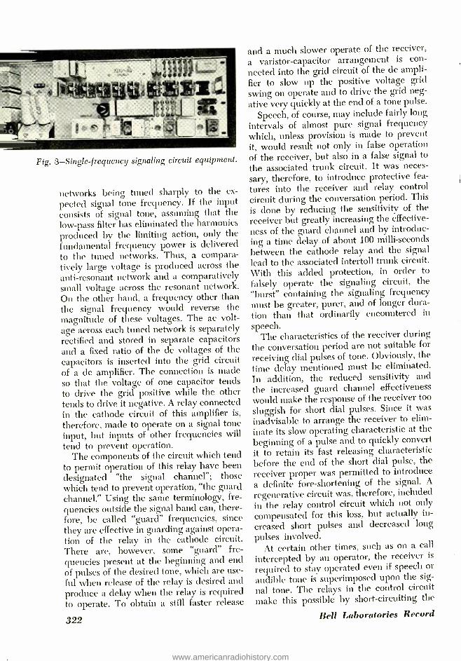
Fig. 3- Single -frequency signaling circuit equipment.
networks being tuned sharply to the ex-
pected signal tone frequency. If the input consists of signal tone, assuming that the low -pass filter has eliminated the harmonics produced by the limiting action, only the fundamental frequency power is delivered to the tuned networks. Thus, a compara- tively large voltage is produced across the anti- resonant network and a comparatively small voltage across the resonant network. On the other hand, a frequency other than the signal frequency would reverse the magnitude of these voltages. The ac volt- age across each tuned network is separately rectified and stored in separate capacitors and a fixed ratio of the dc voltages of the capacitors is inserted into the grid circuit of a dc amplifier. The connection is made so that the voltage of one capacitor tends to drive the grid positive while the other tends to drive it negative. A relay connected in the cathode circuit of this amplifier is,
therefore, made to operate on a signal tone input, but inputs of other frequencies will tend to prevent operation.
The components of the circuit which tend to permit operation of this relay have been designated "the signal channel "; those which tend to prevent operation, "the guard channel." Using the same terminology, fre- quencies outside the signal band can, there- fore, be called "guard" frequencies, since they are effective in guarding against opera- tion of the relay in the cathode circuit. There are, however, some "guard" fre- quencies present at the beginning and end of pulses of the desired tone, which are use- ful when release of the relay is desired and produce a delay when the relay is required to operate. To obtain a still faster release
322
and a much slower operate of the receiver,
a varistor -capacitor arrangement is con -
nected into the grid circuit of the dc ampli-
fier to slow up the positive voltage grid
swing on operate and to drive the grid neg-
ative very quickly at the end of a tone pulse.
Speech, of course, may include fairly long intervals of almost pure signal frequency which, unless provision is made to prevent it, would result not only in false operation of the receiver, but also in a false signal to
the associated trunk circuit. It was neces- sary, therefore, to introduce protective fea-
tures into the receiver and relay control circuit during the conversation period. This is done by reducing the sensitivity of the receiver but greatly increasing the effective- ness of the guard channel and by introduc- ing a time delay of about 100 milli- seconds between the cathode relay and the signal
lead to the associated intertoll trunk circuit. With this added protection, in order to
falsely operate the signaling circuit, the "burst" containing the signaling frequency must be greater, purer, and of longer dura- tion than that ordinarily encountered in
speech. The characteristics of the receiver during
the conversation period are not suitable for
receiving dial pulses of tone. Obviously, the
time delay mentioned must be eliminated. In addition, the reduced sensitivity and
the increased guard channel effectiveness would make the response of the receiver too
sluggish for short dial pulses. Since it was
inadvisable to arrange the receiver to elim-
inate its slow operating characteristic at the
beginning of a pulse and to quickly convert it to retain its fast releasing characteristic before the end of the short dial pulse, the receiver proper was permitted to introduce a definite fore -shortening of the signal. A
regenerative circuit was, therefore, included in the relay control circuit which not only
compensated for this loss, but actually in-
creased short pulses and decreased long
pulses involved. At certain other times, such as on a call
intercepted by an operator, the receiver is
required to stay operated even if speech or
audible tone is superimposed upon the sig-
nal tone. The relays in the control circuit make this possible by short -circuiting the
Bell Laboratories Record
www.americanradiohistory.com

resonant or guard network and by adding a series resistance to the anti -resonant net- work. This eliminates the power of the guard channel and permits all input fre- quencies to contribute to signal channel power thus maintaining the receiver in an operated condition.
Control relays determine what the char- acteristics of the receiver shall be under any given condition and whether the trans- mitter shall follow explicitly orders received from the associated trunk, or shall aug- ment independently signal orders. These relays decide what transmitter and receiver
THE AUTHOR: Before his graduation from the College of the City of New York in 1920, C. W. LUCEK had worked for the Western Electric In- stallation Department during the summer months. After receiving his B.S. degree, he came directly to the Laboratories where he first worked in the systems development group engaged in fitting re- lays into circuits. Later, he became involved in circuit analyzation and in fundamental circuit de- velopment for machine switching. Just prior to World War II, he transferred to the telegraph group where he worked on automatic switching for telegraph circuits. Returning to telephone switching after the war, he has since been con- cerned with single- frequency signaling systems.
conditions shall exist from the knowledge of the order received from the associated intertoll trunk circuit in combination with the signal received from the distant end.
Signaling circuits as shown in Figure 3 are now being manufactured in quantity. Over 9,000 units have already been shipped to the field and approximately 3,500 of these are now in service. About 25,000 of an earlier model, somewhat different in ap- pearance but having essentially the same operating features, have been installed and are in use for over 12,000 toll lines through- out the country.
(Continued from page 317) control panel on which are mounted sub- assemblies containing the limiter- detector and the video amplifier. This unit is also powered from the TD -2 system power plant. Continuous meter indication is pro- vided of the action of the amplitude limiter circuits. A third meter may be switched to indicate the space current of the individual vacuum tubes of the limiter- detector at normal and reduced heater power. This meter may also be switched to read the
July, 1951
peak -to -peak television signal that is being delivered to the 110 -ohm balanced output circuit.
The performance of the FM terminals without any intervening radio equipment is such that with 15 pairs of terminals in tan- dem, over 480 telephone channels may be transmitted simultaneously without exces- sive modulation or noise. The transmission through the terminals back to back is sub- stantially independent of frequency from below 30 cycles to over 8 megacycles.
323
www.americanradiohistory.com
The Key Test- Havana cable
The repeater container
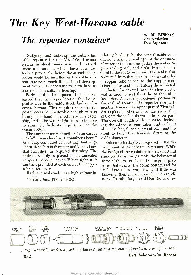
Designing and building the submarine cable repeater for the Key West- Havana system involved many new and untried processes, some of which have been de- scribed previously. Before the assembled re- peater could be installed in the cable sys- tem, however, much thought and develop- ment work was necessary to learn how to enclose it in a suitable housing.
Early in the development it had been agreed that the proper location for the re- peater was in the cable itself, laid on the ocean bottom. This requires that the re- peater container be flexible enough to pass through the handling machinery of a cable ship, and to be water tight so as to be able to resist the hydrostatic pressures at the ocean bottom.
The amplifier units described in an earlier article° are enclosed in a container about 7 feet long, composed of abutting steel rings about 13E inches in diameter and 3 inch long, that furnishes the required flexibility. The entire assembly is placed in an annealed copper tube outer cover. Water tight seals are then provided at each end of the copper tube outer cover.
Each end seal combines a high voltage in-
° RECORD, June, 1951, page 245.
W. M. BISHOP Transmission Development
sulating bushing for the central cable con- ductor, a hermetic seal against the entrance of water at the bushing (using the metal -to- glass sealing art ), and a plastic seal that is
fused to the cable insulation. This seal is also protected from direct access to sea water by a copper tube joined to the copper con- tainer and extending out along the insulated conductor for several feet. Another plastic seal is used to seal the tube to the cable insulation. A partially sectioned portion of the seal adjacent to the repeater compart- ment is shown in the upper part of Figure 1.
An exploded schematic of the parts that make up the seal is shown in the lower part. The over -all length of the repeater, includ- ing the added copper tubes and seals, is
about 23 feet; 8 feet of this at each end are used to taper the diameter down to the cable diameter.
Extensive testing was required in the de- velopment of the repeater container. While the design of the container from a structural standpoint was fairly simple, the behavior of
some of the materials, under the great pres- sures that exist at the ocean bottom and for such long times, was new, and little was known of their properties under such condi- tions. In addition, the difficulties and ex-
COPPER TUBE
OUTER STEEL RING
INNER STEEL RING
GLASS SEAL ASSEMBLY
PLASTIC SEAL PROTECTIVE TUBE ASSEMBLY ASSEMBLY COVER
NOSING PARTS
MAW
Fig. 1- Partially sectioned portion of the end seal of a repeater and exploded view of the seal.
Bell Laboratories Record 324
www.americanradiohistory.com

pense of lifting a deep sea cable for repair, or even the consequences of serious delay during the initial laying operation would be very serious. These problems have justified more than usual conservatism in the factors of safety applied to material constants, the safety features used, and the thoroughness with which the final performance testing was done. For example, although the glass seal was designed and tested to withstand great pressures over a considerable length of time, in actual use the glass seal is pro- tected from the hydrostatic pressures so long as the remainder of the seal functions satisfactorily.
Then, too, although processes for adher- ing plastics to metal have long been in use commercially, early tests and experience
rate under simulated conditions of a failure that would put the plastic seal in direct con- tact with the sea water. The apparatus used to make the diffusivity test is shown in Figure 2. A small cup containing a desiccant is suspended by a quartz fiber spring in a glass tube. The plastic seal under test is mounted just below the glass tube, where water pressure equivalent to that of the sea water at the ocean bottom ( 6,000 to 10,000 pounds per square inch) is applied to it. Water vapor diffused through the plastic seal is absorbed by the desiccant and the incremental change in length of the quartz fiber spring is measured by a travel- ing microscope. Over a period of about five years approximately 17 milligrams of water were absorbed by the desiccant. The rate of
Fig. 2- Herman Alf ke making the diffusivity test, measures the change in length of the suspension of the quartz fiber spring. In this test a small cup containing a desiccant, is suspended from the spring. Incremental change in weight of the cup determines the amount of moisture absorbed.
with these processes indicated a need for im- provements to meet the severe requirements established for this project. A long develop- ment program was undertaken that resulted in reliable seals having excellent adhesive properties.
In the over -all seal design, in addition to the measures taken to prevent direct contact of water with the plastic seal, the develop- ment work included studies of the diffusion
July, 1951
diffusion through the seal begins to taper off after the first year, beginning steady after that time at about 2.5 milligrams per year. Calculations indicated that this rate would not be tolerable for the repeater without additional protection which is provided by the glass seal or, in the event of failure of the glass seal, by a desiccant installed within the repeater.
In addition to testing the seal itself, the
325
www.americanradiohistory.com

enclosed repeaters were given pressure tests. After assembling the repeater up to the point of including the glass seal, the re- peater was very carefully weighed. It was then subjected to ocean bottom hydrostatic pressure for a few days, after which it was re- weighed. If no change in weight oc- curred, it could be assumed that the con- tainer did not leak. A similar procedure was followed after the plastic seals were added.
Weighing was done on a specially de- signed analytical type balance having a maximum capacity of 15 kilograms with a precision of one part in 15 million, require-
FIXED IDLE SHEAVE
REPEATER SAMPLE
WIRE ROPE
WIRE ROPE ANCHORED TO DRUM
CABLE SAMPLE
tated by the presence of repeaters as part of the cable and supplying the ship with the large amount of cable and sample repeaters for an ocean test expedition, would have been a complicated and expensive proced- ure at this stage. Besides, if modifications of repeaters were necessary as experience might prove, facilities for doing this would be unfavorable. For these reasons, therefore, laboratory experiments were made until it was believed that the final design had been reached.
To carry on such laboratory experiments under conditions closely simulating those expected on a cable ship, an imitation ship -designated "C.S. Hi -and -Dry" -was con- structed in the Laboratories' building. Ac- tually, this was only a simulation of a part of the laying machinery of a cable ship. It is shown schematically in Figure 3, and photo- graphs of parts of the equipment, cable, and repeaters in Figures 4 and 5. The machinery consists of a drum to simulate a cable ship brake drum or bow (or stern) sheaves, a motor and gear box to drive the drum, and
REDUCTION GEARS
MOTOR MOVABLE IDLE SHEAVE
SNUBBING WIRE ATTACHED
TO CABLE SAMPLE
Fig. 3- Schematic of the simulated cable laying machinery.
ments representing about the maximum at- tainable in weighing equipment. To help realize this precision, the weighing opera- tions were done in controlled atmospheres of vacuum and dry nitrogen.
How the containers would pass through the machinery of the cable ship was another problem that required extensive study both in the laboratory and on shipboard. These studies were necessary from the standpoint of the effect of handling upon the contained amplifiers and also upon the containers themselves. Much of the development work could be done with the aid of simple bend- ing tests to a curved surface of the proper radius, but as the development progressed, it became necessary to simulate more closely actual conditions at sea. Chartering a cable ship, equipping it with the new devices die-
326
HYDRAULIC JACK
two small idler sheaves. During a test, one of the idler sheaves is fixed in position, while the other is attached to a hydraulic jack used to apply a measured tension to a cable threaded over the sheaves and the drum. The cable, containing a repeater, makes sev- eral turns around the drum and passes through the idler sheaves in a closed loop. Tension on the cable may be varied from zero up to several tons. These tests thus subjected the repeater to more bends and smaller radii, together with greater tensions,
Bell Laboratories Record
www.americanradiohistory.com

Fig. 4- Laboratory apparatus for testing completed repeaters installed in a length of the sub- marine cable. A laboratory armoring machine is in the background.
than it would encounter in actual cable lay- ing operations.
The cables and repeaters used in these tests, of course, had to be completely armored such as the final cable would be. The number of turns of armor wire per unit length of the cable was varied in order to determine the optimum armor design. Since
Fig. 5 -The motor driven drum that simulates a cable ship brake drum.
the armor, under tension, acts like a spring, there is a tendency for it to unwind, so that twisting of the cable under laying could be simulated by varying the tension produced by the hydraulic jack. Slippage of the cable on the drum also could be simulated by varying the tension.
Experience gained from these tests was
Fig. 6 -A repeater can be seen entering the guide pulley line on board ship during the sea trials.
July, 1951 327
www.americanradiohistory.com

valuable in the development of a repeater container that later passed satisfactorily the sea trials and the final laying of the cable. The extreme precautions taken in the devel- opment apparently paid dividends in the final laying because no difficulty was experi- enced in this part of the work. Of course, service in the years to come will offer the final proof.
As in any large development project, many people contributed to the design, con- struction, and testing of the repeater con-
THE AUTHOR: Coming directly to the Labo- ratories after receiving his A.B. degree from Miami University ( Ohio) in 1925, W. M. Bishop's first job was in the magnetics research group. Here he was concerned with improvements in methods of proc- essing magnetic materials. After five years in this work he transferred to the submarine cable devel- opment group where his assignment involved the mechanical development and design of the repeater. He was also in charge of the laboratory where as- sembly of the repeater into the container was per- formed. With the outbreak of World War II, when most of the Laboratories' efforts turned to war projects, Mr. Bishop took part in the development of methods for stringing Army telephone field wire from air craft. Following the war, he returned to submarine cable development, and, upon its com- pletion, has now become engaged in central office maintenance tool design.
tamer. Plastic seals were developed and built under the direction of H. Peters and W. H. Lockwood of the Chemical Labo- ratories; glass seals were under J. E. Clark of Electronics Apparatus Development at the Western Electric Allentown plant; and the drafting was done by H. Mach, Jr., of the Transmission System Drafting Depart- ment. Much of the manufacturing work within the Laboratories' building was done by the Development Shops personnel under H. Holler and G. W. Schnell.
(Continued from page 318) been provided so that the pilot could take over the control of the plane should the re- mote control or the stabilizer fail. The tests were successful, however; for the first time in history a plane was being guided by radio signals from a distant plane.
A second flight was made on September 20 to demonstrate the system to a committee representing the Department of Aircraft Production. Major Paine, Dr. Sabine, and
328
Captain Lake were present, the latter sub- stituting for Colonel Clark. Again Oswald rode in the drone plane; and Captain Lake piloted the primary plane. This test also was a success. A number of short turns and four complete left and two complete right circles were made, in a total flying time of about fifteen minutes.
As a result of this work, two patents were granted to Mr. Oswald: No. 1,501,683 and No. 1,501,684.
Bell Laboratories Record
www.americanradiohistory.com

Organization Changes in Systems Development The following changes in the organization of
Vice President McRae were effective June 18: H. A. Affel has been appointed Assistant
Vice President reporting to J. W. McRae, Vice President. In this capacity, Mr. Affel's primary responsibility is in connection with the technical program of the Systems Develop- ment Department.
The following is the organization of G. N. Thayer, Director of Transmission Develop- ment, in the area of Transmission Systems De- velopment:
A. C. Dickieson has been appointed Direc- tor of Transmission Systems Development I. Reporting to Mr. Dickieson are:
P. G. Edwards, Transmission Systems De- velopment Engineer, who continues to carry his present responsibilities;
H. B. Fischer, Transmission Systems Devel- opment Engineer, who continues to carry his present responsibilities;
T. J. Grieser, appointed Transmission Sys- tem Development Engineer. In this capacity Mr. Grieser has assumed Mr. Thayer's present responsibilities in the area of development of microwave radio.
E. T. Mottram has been appointed Direc- tor of Transmission Systems Development II. Reporting to Mr. Mottram are:
L. G. Abraham, Transmission Systems De- velopment Engineer, who continues to carry his present responsibilities;
J. J. Gilbert, Submarine Cable Engineer, who is responsible for submarine cable de- velopments;
R. E. Crane, appointed Transmission Sys- tems Development Engineer; he has assumed the former responsibilities of Mr. Mottram, with the exception of work for which Mr. Gilbert is responsible.
The following is the organization of G. W. Gilman, Director of Systems Engineering, in the area of Transmission Engineering:
M. L. Almquist has been appointed Direc- tor of Transmission Engineering I. Reporting to Mr. Almquist are:
J. T. Dixon, appointed Transmission Studies Engineer, who is responsible for planning new types of transmission systems;
J. W. Emling, appointed Systems Studies Engineer, who is responsible for economic studies and evaluation of proposed transmis- sion systems;
July, 1951
R. P. Booth, appointed Special Systems En- gineer, who is responsible for engineering studies of military systems;
H. Nyquist and F. B. Llewellyn, who con- tinue their present responsibilities for mathe- matical and theoretical studies.
P. W. Blye has been appointed Director of Transmission Engineering II. Reporting to Mr. Blye are:
L. R. Montfort, appointed Carrier Systems Engineer, who is responsible for the engineer-
H. A. AFFEL
ing of carrier systems and for noise, crosstalk, and inductive coordination studies;
A. C. Peterson, appointed Radio Systems Engineer, who is responsible for the engineer- ing of mobile, point -to- point, and microwave radio systems.
Mr. Blye, continuing in his present capacity as Transmission Engineer, is responsible for television transmission studies, as well as the engineering of exchange area and general toll systems.
After two years at M.I.T. as a research as- sistant, Herman A. Affel joined A T & T, where he remained until his department was consolidated with the Laboratories in 1934.
329
www.americanradiohistory.com

M. L. ALMQUIST P. W. BLYE
In 1949 he became Director of Transmission Systems Development. Mr. Affel has had broad experience in communication work, particularly in the field of high frequency transmission. Some of his most important con- tributions have related to the problems of automatic gain control for telephone trans- mission and automatic volume control for ra- dio. His inventions provided systems in which speech volume or the strength of a radio signal is maintained constant by automatic elec- tronic means, thereby eliminating the necessity of constant monitoring. Mr. Affel has made many contributions toward the development of high -frequency transmission systems, multi- plex carrier current communication systems and long distance telephone transmission. In 1929, with Lloyd Espenschied, he invented the coaxial cable system. He has been granted more than 120 patents on wire and radio sys-
tems, and is the author of numerous technical papers dealing with these subjects.
Alton C. Dickieson joined the Laboratories in
1923 and for the six years worked on carrier telephone systems. After a year in the sound picture industry, he returned in 1930, and re- sumed his work on short -haul carrier. Gradually other responsibilities were added such as voice - frequency repeaters, voice- operated devices and radio telephone control terminals.
During the war his group designed. the fa- mous "Spiral -4" carrier system for back -bone military lines. They also handled electronic design for underwater sound gear. Afterward, he returned to carrier development, and the group concerned with overseas radio was added. In 1948 he became Radio Systems Engineer in charge of all Laboratories' radio engineering for the Bell System including
330
A. C. DICKIESON E. T. MOTTRAM
overseas, coastal harbor, mobile and point - to- point.
After two years in Western Electric Installa- tion, Elliott T. Mottram returned to Columbia from which he graduated in 1928. On enter- ing the Laboratories, he took up work on sound pictures and later became head of the disc recording and reproducing group. During the war and for some years thereafter, he was head of a group which-worked on search radar, radar bombsights, and a radar- guided missile called "The Bat. "*
A year ago, Mr. Mottram was appointed transmission systems development engineer, and given charge of groups working on carrier broadband terminals, testing equipment, sub- marine cable, and military carrier systems.
Milton L. Almquist joined A T & T in 1921 where he engaged in the development of toll equipment, first with radio systems and later with toll signaling and carrier developments. In 1932 he was placed in charge of a group handling toll maintenance and test board de- velopment, which, with the merging of the D & R and the Laboratories in the spring of 1934, became part of the Systems Develop- ment Department. From 1935 until the war, he concentrated on carrier systems engineering. One of his military projects was the Spiral -4
carrier system; another was the Signal Corps' manual on telephone communication systems engineering known as "TM 11- 486." In 1943 he became Transmission Engineer responsible for work on radio countermeasures and other proj- ects for the Armed Forces.
Since 1945 Mr. Almquist has been con-
* RECORD, April 1946, page 137.
Bell Laboratories Record
www.americanradiohistory.com

cerned with planning of new transmission systems such as the microwave radio systems and the Type -O carrier system. He holds a total of 17 patents.
As a member of the transmission division of the Department of Development and Re- search, Paul W. Blye engaged for several years in the deve'_opment of special testing apparatus and methods required in inductive coordination studies. He was subsequently assigned to developmental studies dealing with the wave -shape and inductive influence of power systems, including methods for their control. In 1942 he became transmission en- gineer. During the war Mr. Blye had charge of the air -laid telephone wire project*, and of part of a very important project which is still classified. In 1948 he became transmission systems engineer. His group acts as consultants to the Bell System on such matters as transmis- sion, noise and crosstalk systems. They follow the transmission aspects of Laboratories devel- opments and test the final product. They are also responsible for transmission standards for television as well as audio programs.
Bust of Alexander Graham Bell Placed In Hall of Fame
Busts of Alexander Graham Bell, inventor of the telephone, and Dr. William Crawford Gor- gas, who rid the Canal Zone of yellow fever, were added to the Hall of Fame for Great Americans at a dedication ceremony held in New York City on May 24.
The bronze likeness of Bell, sculptured by Stanley Martineau, was unveiled by the inven- tor's daughter, Mrs. Gilbert Grosvenor, assisted by Marian Hubbard Bates, a great- grand- daughter of Dr. Bell. Mrs. Grosvenor spoke briefly, giving some interesting personal rem- iniscences of her father. Several other descen- dants of Dr. Bell were present at the ceremo- nies, which were held in the auditorium of the library of New York University.
O. E. Buckley, chairman of the board of directors of the Laboratories, presented the bust of Dr. Bell to the Hall of Fame on behalf of A T & T and the Bell System.
Paying respect to Bell as an inventor and scientist, Dr. Buckley characterized him as a man of great vision with strong feeling for others. It was this zeal in helping people to communicate their thoughts and feelings that gave Bell the inspiration that led to the inven-
° RECORD, March 1945, page 150.
July, 1951
tion of the telephone, Dr. Buckley declared. Charles F. Kettering, research consultant to
General Motors, in paying his respects to the memory of the telephones inventor, said that in these tense days we must remember our great Americans as being the main elements of our nation's continuation and strength.
"It was by his (Bell's) own great momentum that the Bell System of today was developed," Dr. Kettering pointed out. "It has been the great inventions of our countrymen that have led to the unceasing creative work that goes on today. And it is this creative work that makes our country strong."
Dr. Ralph W. Sockman, director of the Hall of Fame, presided over the ceremonies, which were witnessed by an audience of 1200 people. Music was provided by Lucile Cummings, and the New York University Chapel Choir.
Marian Hubbard Bates, great- granddaughter of Alexander Graham Bell, places a wreath on the Hall of Fame bust of the inventor, which was unveiled by his daughter, Mrs. Gilbert Grosvenor (left). Looking on is Dr. Ralph W. Sockman, director of the Hall of Fame.
331
www.americanradiohistory.com

Financial Health Is
8c'erbodjfs Business Reprinted from the A T dr T's "195 Bulletin" for May, 1951
When the costs of doing business climb as steeply as they have for us, there's only one way we can meet them.
That's by increasing our rates. For it's only through rates -through the
money our customers pay us for our service - that we can get the money to pay wages, taxes and the many other expenses necessary to our business.
This might be called "Go" money. It's the money that keeps us going.
One Man's Rate Case When a restaurant- keeper finds he can no
longer afford to sell a cup of coffee for a nickel, what does he do?
He takes a pencil, crosses out the 5¢ opposite "Coffee" on his menus and writes in the new figure. That's his rate case.
But we're a public service. When we want to increase our prices, we must go to the com- missions and ask permission. The facts and figures are presented in numerous hearings. Cross -examination follows testimony.
It Takes Time This is slow business. Usually it takes
months. Sometimes over a year. Expenses don't stop rising while commissions
deliberate. So what has happened is that by the time higher rates are granted, our costs have gone up so much more that we're behind again.
BELL SYSTEM AVERAGE EARNINGS, BY PERIODS, SINCE 1920
POST WAR BOOM
DEPRESSION
_RECOVERY
WAR POST WAR
BOOM
ll Ì I (`
s e f
IpuuIuuulpp p iiuiiiii III III
NOON III
I. .. NOON N
6
4
1920 1925 1930 1935 1940 1945 1950
In the booming period since World War II, our earnings have been almost as low as during the depression.
332 Bell Laboratories Record
www.americanradiohistory.com

That's a good part of the trouble right now. We're stuck with inflation.
Just for example. All the rate increases we've been granted add up to only a little more than half the current annual cost of our wage in- creases alone in the war and post war periods.
But wages aren't all. Taxes and materials have gone up, too -and plenty!
How Do We Grow? Having sufficient rates is important for an-
other reason besides making ends meet. When most other businesses want to enlarge
or improve their plant so as to make more and better goods, they can pay for it largely out of their earnings.
We can't. As a regulated business our profits are strictly
limited. We are not permitted to earn enough to buy, out of profits, the new trucks and buildings, cable and switchboards we need in order to expand.
Yet we've got to grow and expand. We are obligated to give telephone service when and where it is wanted. It's our responsibility, too, to give the best possible service and to keep on improving it.
Where the "Grow" Money Comes From Where do we get this new money -where do
we get this "Grow" money that pays for the equipment we use in our jobs?
We get it from investors. From men and women who are willing to risk their savings in our business.
But they will do this only so long as we are able to pay them a reasonable return for the use of their money -and also show promise of
financial health for the future. We can't be depended upon if rates are too low. If people can get a better and safer return from some other business, naturally they'll invest their money there. Wouldn't you? That's why rate cases are everybody's business.
Earnings Have Been Low Since the war the Bell System's earnings
have been the lowest ever -except for the worst years of the depression.
In the five years before the war, our average earnings were 6.5 per cent on the total money invested in the business. In the five years after the war they were 5.4 per cent. That's about one -sixth less. Yet this was a time when they should have been very good. It was a time of heavy business. There were more telephone jobs than ever.
In 1950 we came part of the way back. And it was about time. Earnings were still too low for boom times like these, but it was the first time in a decade that we had our chin above water. Yet further rises in costs are already cancelling out much of that gain. And in the remainder of this year our wage and tax ex- pense is sure to go even higher.
Higher Rates Essential As a result, the companies have had no
choice but to go back to the commissions again in many states to ask for higher rates. They are essential if we are to have the "Go" money for good service and good jobs. They are equally essential if we are to attract the "Grow" money to keep the business expanding and improving. Getting enough "Go" and "Grow" money is very important to us all.
William Shockley Elected To National Academy
One of the highest awards to an American scientist has recently been received by William Shockley, who was one of twenty-nine Ameri- can scientists recently elected to membership in the National Academy of Sciences. Mem- bership in this Society now totals 481.
Dr. Shockley was born in London in 1910, and came to this country in 1913. He was grad- uated from California Institute of Technology in 1932, continuing his studies at MIT, receiv- ing his Ph.D. degree in Physics in 1936. The same year he came to the Physical Research Department of the Laboratories, where his work involved research on the physics of metals and alloys until World War II became immi-
July, 1951
nent. During the war, he was assigned to Columbia University, Division of War Re- search, on an OSRD contract as Director of Research for Anti- Submarine activities. Later, he became expert consultant in the office of the Secretary of War. Returning to the Laborato- ries following the war, he is now in charge of a department concerned with Transistor physics.
Vail Medal Awards The National Vail Committee of Award an-
nounced on May 9 that 49 bronze Vail Medals had been awarded to telephone employees of the associated companies in 1950. No national Gold or Silver Vail Medals were awarded. This brings the total number of awards, since the Theodore N. Vail Memorial Fund was estab- lished in 1920, to 1,421.
333
www.americanradiohistory.com

Where There's A Will There's A Way
Educational Insurance
L. H. BUNTING, Insurance Counselor
The following data and information will, I hope, be of interest to those members of the Laboratories who are parents and to those others who are directly interested in a plan to provide a college education for children. Every- one knows that it costs money to do this, but everyone does not know that it requires a plan to accumulate this money. It also requires the will to carry out the plan and to see that the money is not subsequently diverted to other uses. If there is this will then there is also the way and that way is the Insured Plan.
Recent research surveys have been made by a number of large organizations interested in this subject which reveal some interesting sta- tistics. For example: twenty years ago there were less than two million college graduates in the United States -today there are more than five million. Twenty years ago there was one woman graduate to every four men graduates -today there are three women to every four men graduating each year. Today there are almost two and a half million students in Am- erican colleges. It is estimated by some college officials that by 1965 there may be fifteen mil- lion college graduates in the United States. This national interest in higher education makes it imperative that we plan now for our chil- dren. It is obvious that if they are to have a fair chance it is up to their parents to help them get into college, if they are prepared to do college work.
These studies, with over two hundred of our leading colleges and universities cooperating, show that the average yearly cost for a student today is over $1200. This is divided approxi- mately as follows: $400 for tuition, fees, books and necessary equipment $500 for room and board; and $300 for clothes, laundry, amuse- ments, travel, and incidentals. At many of the eastern colleges the total will be about $2000. These figures do not include anything for main- tenance during summer vacations, fraternities or sororities. etc.
Between three and four per cent of the students entering college each year secure
334
scholarships from one source or another which pay a part of the costs and many enterprising youngsters secure paid work while at college and during summer vacation. The colleges say that 700 per hour is the average earned by these students and that about fifteen hours per week is the maximum they can safely work and keep up their studies. So, if a student works while at school and during the summer he can accumulate, at the most, between $600 and $700 toward the cost of his education, thus leaving approximately half of the costs for Dad.
Every parent has this ambition for his chil- dren; in fact it is inherent with parenthood, but the ambition is one thing and the accom- plishment is another. There are many ways to accumulate the funds for this purpose and no doubt most of them are good. If a father could be sure that he would live until his youngest child had finished college, he could set aside each year sums which with interest would provide for the education he has plan- ned for each child. Statistics, show, however, that one father in five does not live to see his children through college and many more be- come disabled or incapacitated. These hazards can be offset by insurance. A father can take out an endowment policy, which will mature when the child is, say eighteen. If he dies, the face value will remain on deposit with the insurance company, accumulating interest until its maturity date; if he lives, the basic ex- penses of college have been provided for. In case of disability the plan continues, for the required payments are maintained by the in- surance company until the plan matures or the father recovers and resumes deposits.
Also under the insurance plan it is possible to have an agreement whereby the insurance company will pay out the funds in monthly installments for ten months each year with an additional amount each September and Feb- ruary when it is necessary to pay for tuition, books, etc. One scheme often used is to ar- range for a payment of $75 each month for
Bell Laboratories Record
www.americanradiohistory.com

ten months with an additional payment of $250 on the first of September and February making a total of $1250 each year or of $5000 over a period of four years. Another suggested plan is for payments of $100 monthly with $300 additional in September and February, thus providing $1600 each year or $7200 for a four -year course.
The cost for such a plan will vary accord- ing to the type of life insurance policy selected. An Ordinary Life or a Limited Payment Life policy will assure the completion of the plan in the event of the death or disability of the father or will provide a substantial part of the needed funds otherwise through its cash values and accumulated dividends. An endowment policy on the other hand will guarantee the completion of the plan and the delivery of the funds in full whether the father lives or dies.
One of the great compensations of parent- hood, and indeed one of the most satisfying experiences we fathers can have, is to attend the graduating exercises for our children and to proudly see them receive the diploma for which we both have worked so hard. So, as I say, "Where there's a will there's a way," but that way is made much easier if you start your
Vice President Phalen of A T & T addressed the executive staff of the Laboratories on May 17 on the need of the Bell System for additional revenue. He was introduced by Dr. M. J. Kelly.
July, 1951
plan now and pay out a small amount each month while you have time in your favor rather than to wait and have to do it the hard way.
Hal S. Dumas Elected President of Pioneers
Hal S. Dumas of Atlanta, Georgia, has been elected president of the Telephone Pioneers of America for the year beginning July 1, 1951. He succeeds Frederick Johnson, who is presi- dent of the Bell Telephone Company of Canada.
"The Telephone Hour" NBC, Monday Nights, 9:00 p.m.
July 2
July 9
July 16 July 23 July 30 August 6
August 13
August 20
August 27
Ken Christie's Male Chorus Michael Rabin, violinist
Lucile Cummings, contralto Grant Johannesen, pianist Barbara Gibson, soprano
Ezio Pinza, basso Eileen Farrell, soprano
Oscar Levant, pianist Nelson Eddy*, baritone
°From Carnegie Hall
Mr. Dumas, who is president of the South- ern Bell Telephone and Telegraph Company, served as senior vice -president of the Pioneer Association last year. He is succeeded in that post by William A. Hughes of Newark.
Sandia Notes L.. M. Gambrill, formerly in the cable en-
gineering group at Murray Hill, has been ap- pointed Superintendent of Staff and Business Methods at Sandia. He replaced Frank Cowan, who has returned to West Street. Since going to Sandia in January, Mr. Gambrill had been in charge of the Technical College Recruiting Program.
C. N. Hickman, who retired from the Labo- ratories last year, is now a Member of the Staff of the Sandia Laboratories. His interest in archery is now combined with fishing -recently he brought in six carp, shot with a special arrow having a line attached.
While in Honolulu on vacation recently, Mr. and Mrs. R. E. Poole were guests of Admiral A. W. Radford, Commander in Chief of the Pacific Fleet. A high spot was a tour of Pearl Harbor on the Admiral's barge, including a visit to one of the newest submarines.
335
www.americanradiohistory.com

BELL SYSTEM EXHIBIT SHOWN AT THE LABORATORIES
P. H. Schmitt, Jr., looks at a photograph of himself taken when he was measuring the tern - perature in a controlled atmosphere furnace, rasing an optical pyrometer.
A. W. Clement speaking to a group of Murray Hill people from the platform of the silver - dollar machine.
To inform members of the Laboratories of the financial requirements of the Bell System, particularly with respect to the need for in- creased telephone rates, an exhibit prepared by the A T & T Information Department was shown recently at West Street, Murray Hill and Whippany. The exhibit had originally been pre- pared for use at the 1951 Annual Stockholders Meeting, and is now being shown to employees and others throughout the Bell System.
Two panels containing animated graphs show in brief and easily understood form the Sys- tem's growth and financial needs. Other panels have large photographs that illustrate the wide variety of employee occupations in the System, including samples of Bell Laboratories activi- ties. In addition, a demonstrtor- operated mechanism is used to supplement a speaker's lecture on financial needs. This machine is ar- ranged to show the System's increase in annual expense and income by means of columns of silver dollars.
The exhibit was open to visitors for one week each at West Street and Murray Hill, and for two days at Whippany. Speakers at New York were W. W. Schormann, J. T. Lowe, J. M. Barstow, and E. W. Olcott, with H. H. Abbott serving as alternate. Mr. Schormann and Mr. Lowe spoke also at Murray Hill and Whippany. with A. W. Clement and T. A. Durkin assisting at Murray Hill. Receptionists were always on
www.americanradiohistory.com

duty at each location. At West Street, these were Eleanor Burden, Dorothy Maier, and Florence Greene; at Murray Hill, Marjorie Proctor, Lois Foster, Muriel Kossuth, and Har- riet Hoffman, and at Whippany, Pat Callahan and Alice Charlton. Virginia Hamilton assisted in the set -up and operation of the exhibit at all locations.
A. C. Walker Honored by the Franklin Institute
Word has been received by the Laboratories that A. C. Walker has been awarded unani- mously the Louis Edward Levy medal of the Franklin Institute, Philadelphia, "in recognition of his outstanding paper, Growing Piezoelec- tric Crystals, appearing in the December, 1950, issue of the Journal of the Franklin Institute."
Dr. Walker was graduated from MIT in 1918 with the degree of S.B. in Chemical Engineeer- ing. Previously he had studied two years at the University of Colorado. In 1923 he received the Ph.D. degree in Physical Chemistry from Yale University. Coming to the Laboratories in 1923 after several years as research chemist in the field of textiles and paper research, he has been concerned principally with the electrical prop- erties and dyeing of textiles and with the pro- duction of synthetic piezoelectric crystals. During World War II he operated a pilot plant at the Laboratories for the production of these crystals that were used principally for sub- marine detecting devices. Since the war, his activities have been in research on the growing of artificial quartz crystals.
Bell Symphony "Pops" Concert Several members of the Laboratories took
part in the "Pops" concert given by the Metro- politan Bell Symphony Society on June 1. They were L. N. St. James, flute, A. L. Whitman, viola, H. C. Green, clarinet, W. A. Krueger, bassoon, and P. E. Mills, double bass. On the program were a range of orchestral numbers, from popular to classical. An added attraction was Miss Anita Jordan, soprano.
Communication Development Training Program
Part of the activities of the Communication Development Training Program have been moved to Murray Hill. Some of each school day is spent in attending lectures, studying, or ex- aminations. The pictures show some of the members of the class of '49 during a session devoted to electron tubes and varistors. The
July, 1951
instructor for this course is C. T. Goddard. As a result of the man power shortages
brought on by the defense effort, the Training Program at Murray Hill is now conducted on a one day a week basis after the first intensive
Seated from left to right, J. M. Trecker, A. R. Noland, Q. W. Simkins, S. E. Church, L. B. Valdes, G. H. Robertson, and R. E. Sherman.
Left to right, W. A. Reenstera, J. H. Vogelson, W. J. Lesser, E. G. Baldwin, L. C. Thomas, G. E. Fessier, W. O. Fleckenstein, W. J. Ritchie, J. R. McCrory, J. M. Barstow, Jr., L. G. Swart, and F. H. Shorkley.
year on a three -day a week basis. When not at- tending classes or studying, the students are as- signed to temporary work locations in various departments of the Laboratories. After four such assignments the men return to their sponsoring departments where they begin the attack on telephone problems that will form their life -work.
337
www.americanradiohistory.com

R. E. ALBERTS 40 years
T. J. MURTHA 40 years
J. A. BURWELL 35 years
R. T. JENKINS 35 years
W. H. MARTIN 40 years
July Service 40 years
R. E. Alberts E. S. Gibson R. C. Jones W. H. Martin S. C. Miller T. J. Murtha
35 years
J. A. Burwell R. E. Curran H. W. Dippel J. G. Ferguson B. H. Jackson R. T. Jenkins A. A. Oswald G. C. Reier D. F. Seacord H. F. Shoffstall H. L. Walter
30 years
H. Alike H. S. Black R. L. Case W. Cernik A. J. Christopher W. H. Edwards O. C. Eliason H. A. Etheridge T. C. Henneberger R. E. Keim G. V. King A. G. Laird R. S. Leonard Hazel Mayhew C. G. McCormick
J. G. FERGUSON 35 years
R. C. JONES 40 years
Anniversaries B. A. Merrick V. M. Meserve Andrew Mogilski D. L. Moody W. J. Pinckney K. F. Rodgers J. T. Schott N. R. Stryker Allan Weaver A. D. Williams H. M. Yates A. W. Ziegler
25 years
E. E. Arnold H. W. Bode H. G. Boyle A. T. Calvano Frank Colantuoni T. L. Dimond D. W. Eitner M. S. Glass L. B. Hilton F. W. Holland R. P. Jutson G. F. Kallensee H. A. Lewis C. E. Luffman H. P. Lynch Joseph Maurushat K. H. Muller J. L. Murphy C. R. Noble A. F. Noe W. T. Rea John Riordan J. H. Shuhart C. F. Smith
H. W. DIPPEL 35 years
E. S. GIBSON 40 years
of Members of the F. R. Stansel W. R. Steeneck N. H. Thorn D. E. Trucksess P. W. Wadsworth Karl Wittmann
20 years
J. J. Carroll R. C. Gee C. A. Naughton R. C. Platow F. M. Tylee C. A. Warren
15 years
F. S. Best B. S. Biggs F. J. Biondi H. A. Birdsall J. J. Boese D. C. Bomberger J. J. Cremins J. F. Daly R. V. Dean F. E. DeMotte C. H. Elmendorf G. R. Frantz J. L. Garrison C. C. Houtz G. D. Johnson Muriel Kossuth Marie Kummer John Lavelle Nean Lund R. W. Marshall J. J. Martiner
B. H. JACKSON 35 years
S. C. MILLER 40 years
Laboratories F. E. Radcliffe J. M. Sullivan M. Tomb
10 years
G. H. Baker A. F. Bartinelli G. M. Bloss W. H. Burgess A. Christiansen R. W. Dawson H. E. Driscoll E. R. Fitzgerald W. R. Grant W. V. Hoshowsky E. H. Jockel A. C. Johnson R. E. Johnson H. V. Kahlke W. D. Lewis Anthony Lizdas C. F. Muegge R. I. Nolan j. P. Noll Claire Ohl J. A. Pecon Ann Pfeiffer W. F. Rauchle P. F. Reckenzaum Ruth Robinson G. A. Roe H. J. Rohr J. K. Schoolcraft Jean Seal S. P. Sheldon G. T. Stanley A. C. Wohlgemuth
R. E. CURRAN 35 years
www.americanradiohistory.com

G. C. REIER 35 years
H. F. SHOFFSTALL 35 years
D. F. SEACORD 35 years
Changes in Organization The following changes in the organization
of M. H. Cook, Director of Apparatus and Sys- tems Engineering, became effective on June 1, 1951:
R. G. Koontz was appointed Director of Standards and Drafting reporting to Mr. Cook. D. S. Myers as Standards and Records Engi- neer reports to Mr. Koontz. Mr. Myers' staff has been divided into two groups in charge re- spectively of A. F. Burns and C. Erwin Nelson. In Mr. Burns' group are W. H. McAuliffe, Ap- paratus Coding; T. G. Fischer, General Prac- tices; C. H. Heller, Standards Handbooks; and H. L. Holley, Standards Applications. Reporting to Mr. Nelson are H. W. Hodgkins, Editing and Printing; and Marion Canavan, Records and Files.
Mr. Koontz continues to give supervision to the apparatus drafting group through H. Han- sen, who replaces the late George Dodd. The switching apparatus specifications group under D. O. H. Weston will also be supervised by Mr. Koontz.
In anticipation of the retirement of H. E. Marting on August 1, his work on repaired apparatus has been distributed between the specifications groups at Murray Hill and West Street, combining the repair and specifications functions by apparatus areas. A. B. Reynolds, formerly in charge of the repaired apparatus group, has transferred to Murray Hill, where he is in charge of Station Apparatus. Specifica- tions. F. S. Wolpert, who has been tempo- rarily in charge of Station and Outside Plant Specifications, has charge of Outside Plant, Government and Equipment Specifications.
V. H. Baillard, as Assistant Plant Products Engineer, is now associated with S. C. Miller, Plant Products Engineer, in leadership of the Outside Plant groups concerned with develop- ment of cable terminal and protection appara- tus and of tools and pole line hardware.
With the retirement of R. P. Ashbaugh the cable engineering group at Kearny now re- ports to C. Kreisher, who has been appointed
July, 1951
A. A. OSWALD 35 years
H. L. WALTER 35 years
Cable Design Engineer and transferred from Point Breeze to Kearny. By a concurrent change, the toll cable design group at Point Breeze, headed by R. E. Alberts and previously under the general supervision of Mr. Ashbaugh now reports to O. S. Markuson, Toll Cable Engineer at Point Breeze.
The following changes in the Switching Engineering Department organization were effective June 1, 1951: W. O. Turner of the Operation and Engineering Department of A T & T accepted a position as Switching Engineer in the Bell Telephone Laboratories in charge of a new Department 3160, report- ing to F. J. Singer, Director of Switching Engineering. In this capacity, Mr. Turner is responsible for probability engineering, prob- ability research, and traffic instrumentation. C. E. Brooks, Consulting Engineer, Department 3150, has been appointed Switching Engineer in charge of that department, which will be engaged in long range studies relating to switching systems. W. W. Carpenter, Consult- ing Engineer in Department 3150, continues in this capacity in a new Department 3170.
In Murray Hill Area Staff Department De- velopment Shop A. E. Emerson, Superinten- dent of the Development Shop, recently as- sumed duties in connection with a Special Mili- tary Project in Department 4500. F. W. Brun - nengraber, appointed Superintendent replacing Mr. Emerson, will assume duties of that posi- tion along with his present assignment on Shops Planning.
In the General Service Department at Mur- ray Hill Jean Maloney recently assumed duties as secretary to A. H. Inglis replacing Virginia Allen, at present on leave of absence. In the Restaurant Eleanor H. Drake recently assumed duties as Supervisor replacing Cath- erine Clynes who resigned.
Following Anna Kieman's death, the secre- tarial and transcription service has been re-
341
www.americanradiohistory.com

organized. Ethel Carr has charge of the 2G typing group, supported by three leaders: Con - cetta Adorno, who is responsible for the work of the newer typists; Angeline McDermott, who has the assignment of all telephone dic- tation; and Elizabeth Kerr, who is the leader of the special typists, including those who pre- pare BSPs.
Eleanor Ringel will continue to supervise the stenographers in 2D. She lias also assumed responsibility for the mimeograph and dupli- cating group, with Mary Sullivan immediately responsible for the work there.
A new division has been set up comprised of the branch, or local, transcription services under the supervision of Rose Rovegno. This division, which it is hoped can later be ex- panded, is at present made up of the Graybar- Varick group, under Mary Fitzsimmons; the Ninth Floor, under Mary Casey; the Sixth Floor, for which no supervisor has as yet been appointed; and the specially assigned people serving the library, payroll and accounting, and personnel.
Joyce Thompson is continuing in the capac- ity of supervisor of secretarial service.
E. Alisch of Department 5821 has become a Drafting Supervisor. R. I. Forrest, formerly of the Drafting Department, has become a Technical Staff Associate in the Standardization Group and Alexandra Sismanoglu, also for- merly of the Drafting Department, has become a Technical Assistant in the Apparatus Cod- ing Group.
Technical Assistants of Department 4000 who have become Technical Staff Associates are Shirley Holt, Elizabeth Lockey, Alice Loe, Elizabeth Zobel and Joseph Kocan.
The following Messengers have become Junior Clerks in the Drawing and Specifica- tions Files of Department 5000: Blanche Dom- ino, Joyce Hollender and Dorothy Kramer.
Dorothy Mason, R. C. Benkert, G. Chabra and C. J. Yunger, formerly of the Drafting De- partment, have become 1 echnical Aides in the Specifications Department.
Arts and Crafts Exhibit One of the most interesting and best attend-
ed arts and crafts exhibits sponsored by Bell Laboratories Club was held in the Lounge area at West Street during May. There were 123 entries in oils, watercolors, sculpture, ceramics and handicrafts made by Club members in New York, Murray Hill, Whippany and Allentown, and by retired members of the Laboratories. Eighteen of the entries which were displayed were purchased by visitors to the exhibit.
Winners in Oils were: Patrina Caruso first prize for Study from Life; Gloria Artal, second; and John Neill, third; in Watercolors, Daniel Lashen, first prize for Street Scene; M. K.; Zinn, second; and Charles Luffman, third; in Ceramics and Sculpture, Ruth Boyajian, first prize for Evening Prayer; Jewel Haege, second; and Fred Frampton, third. The judges were Everett Draper and Harold Pond.
In the Handicraft entries, judging was by popular vote. The first prize went to H. Hoyle for his coastal steamer; second, Gertrude Paul for a hooked rug; third, V. Lundahl, for his clipper ship; fourth, W. Buckland, for a turned salad bowl; fifth, W. De Zavala, for his handknitted ski sweaters; and sixth, Max Guimpel for a tooled leather portrait of George Washington.
Left -Mr. Hoyle with his coastal steamer which received first prize in handicrafts. Right -Alice Loe discusses Leo Montamat's entries with T. C. Campbell and Mr. Montamat, retired. Mr. Mon - tamat had three entries in oils in the Arts and Crafts exhibit. Eighteen paintings displayed in the show were purchased by members of the Laboratories.
342 Bell Laboratories Record
www.americanradiohistory.com

1111111R 11II IOU N POP" "N. !Pr
Pioneers Week -End At Pocono Crest
Ninety pioneers and their guests spent the week -end of May 25 -27 at Pocono Crest, Pocono Pines, Pennsylvania, in one of the most pleasant get -together parties sponsored by the Frank B. Jewett Chapter. Nine Life Club members attended and several of them brought their families. There were outdoor sports of all kinds, including cro -golf and golf during the day with games, square dancing and card playing during the evening entertainment. Prizes were awarded for the various activities.
Members of the week -end party included the group above. Left to right, C. J. Wismar, Harold Schmitt, Mr. and Mrs. S. J. Brymer, Mrs. Ferguson, Mrs. Wismar, J. G. Ferguson, Mrs. Schmitt, Mrs. Lewis and H. A. Lewis. Below, left, Maude Marks, Elsie Dittmar, E. B. Smith, L. C. Plotner, Mrs. Plotner, Mrs. Smith, Mrs. Folkner, G. W. Folkner, Mrs. Richards, and C. B. Richards. Below, right, Harold Schmitt, Chairman of the entertainment com- mittee, New York Council, and General Service Manager at West Street, congratulates the three Pioneer golfers who tied for first prize. Golfers are S. J. Brymer, W. F. Malone and L. W. Drenkard.
News Notes M. J. KELLY participated in the Bell System Presidents' Conference at the Waldorf- Astoria, May 1 to 3. With J. B. FISK he attended the dedication of DuPont's new research Labora- tory in Wilmington, Delaware. Dr. Kelly also attended the dedication of the new Basic Scien- tific Research Institutes Building at the Uni- versity of Chicago and addressed the group at a luncheon. His talk was entitled The Insti- tutes for Basic Research -Their Contribution to National Strength. DR. KELLY AND D. A. QUARLES held a confer- ence at Murray Hill with members of the Air Force Research and Development Command. It was attended by Major General D. M. Schlatter, Major General D. L. Putt, Brigadier General D. N. Yates, Brigadier General R. P. Swofford, Jr., Brigadier General D. Keim, Lieutenant Colonel T. F. Walkowicz, Doctor L. N. Ridenour and Doctor S. M. Skinner. BECAUSE of the high voltage used to supply power to auxiliary repeater stations, corona noise is sometimes experienced on coaxial cables. J. M. DUNHAM and J. H. HARDING have been engaged in corona studies at Modena, New York, and P. W. BLYE recently visited them to review the data obtained.
July, 1951 343
www.americanradiohistory.com

H. W. BAKER W. C. OAKES
RETIREMENTS Recent retirements from the Laboratories
include H. W. Baker and W. H. Bendernagel with 41 years of service; W. C. Oakes, 38 years; L. L. Bouton, 35 years; and H. L. J.
Siedentop, 29 years.
HALSTED W. BAKER
Included in every telephone conversation are two supervisory relays, which tell the op- erator (or the mechanism) when the sub- scribers lift and replace their respective hand- sets. Because these relays are in the talking path, they must introduce a minimum trans- mission loss, and yet they must operate reli- ably over the various line conditions. Because he has been designing supervisory and line relays for over thirty years, Halsted Baker knows as much about them as anyone in the Laboratories. He has presided at the birth of
many types, as the availability of new ma- terials and manufacturing techniques have
uncovered new possibilities. Mr. Baker entered the Laboratories in 1910,
when he became an inspector of central office
installations. He was one of the testers on the first "semi -mechanical" office in Newark, and after that was a laboratory tester on early dial circuits. During his years of relay engineering, he has taken thirteen out -of -hours courses, the last one a war -time course in First Aid.
Except for summer visits to New England, Mr. and Mrs. Baker expect to stay in Chatham, N. J., where they have lived for many years. An inducement to remain is their son and their three grandchildren, all of whom live nearby.
\V. H. BENDERNAGEL
In the years since "Bill" Bendernagel joined the Laboratories, long distance telephony has progressed from voice- frequency service over wires to the modern carrier and radio plant.
344
Soon after he entered, Mr. Bendernagel was put on repeater development, and he installed the first "Shreve" repeater at Syracuse on a
circuit of the New York Central Railroad. He took part in constriction of repeaters for the Transcontinental Line, in building apparatus for the Arlington radio tests, and in the initial carrier tests between Baltimore and Pittsburgh. That was designated the "A" carrier system; and Mr. Bendernagel has had part in the equip- ment development right down through the "N" system, one of the latest in this great family. Other special jobs were the equipment phases of straightforward trunking between Philadelphia and Baltimore, the two -way trans- atlantic radio; the ship -to -shore system for S.S. Leviathan and a number of overseas radio systems. During this period -in 1922 to be exact -he went over from circuit to equipment development.
In World War II Mr. Bendernagel worked on equipment phases of Sonar, spiral 4- carrier, and digital relay computers for the Army, Navy and Air Force laboratories. Since then, he has been concerned with new types of switchboard, the initial installation of NI car- rier, the single- frequency tone signaling sys- tem, and a selective calling system for mobile telephones.
Always a happy, vigorous personality, Mr.
W. H. Bendernagel at his retirement reception.
Bell Laboratories Record
www.americanradiohistory.com

Bendernagel looks back on his 41 years° with the Bell System as a wonderful experience. He and his wife look forward to their new home in South Egremont, Massachusetts, where they are moving from Queens Village. Putting on the finishing touches in the form of flowers and interior finish, and entertaining their daughters and their grandchildren will keep them both busy.
WILLIAM C. OAKES
If grandchildren mean anything in a man's later years, Bill Oakes' retirement will be a happy one, for he has ten, and four children, all married, for good measure. So he and Mrs. Oakes will stay right in their home in Arling- ton, N. J., except for summers in Western New York State.
Mr. Oakes joined us in 1920, with some pre- vious experience with A T & T and New Jersey Bell. After four years analyzing orders from various telephone companies for specific equip- ment he transferred to trunk circuit design for manual service. He has worked on straight- forward circuits, trunks from dial to manual, and that important group of circuits which link community dial offices to their master boards. Some years ago he gave an Out -of- Hours course on manual operation for which he wrote the instruction text. Recently he has been active on the key -pulsing circuits which play the little tune when certain manual boards trunk into a nearby dial office.
LEwIS L. BOUTON
When L. L. Bouton entered the Engineering Department of the American Telephone and Telegraph Company in 1916, the first extensive test of four -wire circuits had just been com- pleted, and plans were being made for the development of four -wire systems suitable for wide commercial use. Mr. Bouton's early work dealt with the application of repeaters to two - wire circuits and the design and development of four -wire cable systems. He had charge of field trial of the extra- light -loaded four -wire circuits between York, Reading, and Harris- burg} and the later trial of the extra- light- loaded two -wire cable system. He was also concerned with the over -all transmission design of voice and carrier circuits and the nation- wide toll switching plan.
During the war, Mr. Bouton worked on voice -frequency repeaters and other "pack- aged" telephone equipment for the Army.
Two of them before he joined the Laboratories. } RECODO, December, 1938, page 116.
July, 1951
Until last summer he had been making trans- mission studies in connection with four -wire switching and nationwide toll dialing; at that time he was taken ill and has since been ab- sent because of disability.
HENRY L. J. SIEDENTOP
Harry Sieden top's career in the Laboratories was devoted to the metallurgy of precious metals in which he prepared thousands of alloy castings for experimental work in contact metals. His knowledge of the behavior of such
L. L. BOUTON H. L. J. SIEDENTOP
elements as gold, silver, palladium, platinum, rhodium, ruthenium, osmium and iridium in melting, as well as in fabricating, was instru- mental in the development of many of the current precious metal contacts.
For his retirement Mr. Siedentop has no special plans. His wife, two daughters and four grandchildren will help to keep him happy out in Scotch Plains. An only son died in World War II. Mr. Siedentop has many hob- bies to fall back on. As a boy he learned weaving from his parents and has retained an interest in the craft; and he is a proficient photographer.
News Notes W. C. TINUS has been initiated into the Texas Delta Chapter of Tau Beta Pi, honorary en- gineering society. He was invited to become a member by his Alma Mater, Texas A. & M.
STUDIES of the effects of open -wire extensions of cable circuits on type -N carrier will be made this summer between Harrisburg and Sunbury, Pennsylvania. C. S. Thaeler of the O & E and I. M. KERNEY, J. MALLETT and L. R. MONTFORT visited Harrisburg to discuss the proposed tests with the Bell of Pennsyl- vania engineers. Problems in the equalization of long type -N systems sent R. D. FRACASSI,
345
www.americanradiohistory.com

J. J. MAHONEY, JR., and E. H. PERKINS to Indiana, where two Indianapolis -South Bend systems are being placed in service. Important copper savings will be realized if arrange- ments can be worked out for operating type -N systems in the same cables with Type K -2 sys- tems. A typical layout was set up between Green Bay and Marinette, Wisconsin, where E. BLOOM, JR., L. HOCHGRAF, T. W. THATCHER, JR., and G. P. WENNEMER conducted tests to determine what coordinating measures are required.
ESTHER RENTROP and V. SUBRIZI recently visited Atlanta, Georgia, to measure loudness of speech volumes on local and toll telephone circuits. These measurements were a part of a general survey of speech volumes in various parts of the country. In connection with these measurements of G. C. REIER and N. W. Mac- Lean of A T & T also visited Atlanta to confer with Southern Bell Telephone engineers.
MANUFACTURER'S modifications to improve the accuracy and extend the field of use of existing Hickok vacuum tube testers required the
presence of A. A. HEBERLEIN, with P. N. de- Grace of Western Electric, at the plant of the Hickok Electrical Instrument Company at Cleveland. O. D. GRISMORE and N. KNAPP, JR.
assisted Long Lines engineers at Philadelphia in making studies of coaxial office layouts at the Race Street Building in anticipation of the forthcoming initial installation of L3 carrier.
H. W. HERMANCE visited Pittsburgh, Cincinnati, St. Louis, Chicago and Cleveland to study how chemistry and physics can help in the cleaning of panel system contacts and in keeping them clean. A new multiple brush cleaning proce- dure is to be tried out in the Superior Office in Chicago and improved sleeve terminal lubri- cation in Pittsburgh and Cincinnati. C. W. MATTSON participated in the Pittsburgh studies.
MUCH ACTIVITY is underway in the develop- ment of transmission networks for various types of military equipment. These include filters, delay equalizers, attenuation equaliz- ers, pulse shaping networks and computer networks. Winston- Salem, where many of these networks are to be manufactured, was
346
Whippany Men's Glee Club Party E. J. McGarry, R. C. Winans, and M. W. Dring, accordion trio.
The Glee Club quartet, The Belltones, B. J. Thomas, W. L. Shaffer, W. E. Ingerson and R. O. Sinclair entertained the Whippany Men's Glee Club and their guests at their annual party at the Canary Cottage in Florham Park.
Soloists for the occasion were A. F. Duerr and Audrey Glazar, wife of C. Glazar of the Glee Club. H. G. Och, the Club accompanist, also played several solos during the evening.
Bell Laboratories Record
www.americanradiohistory.com

H. M. JAMISON
Called to Active Duty During May two leaves of absence were granted, bring-
ing the total to thirty -six since June, 1950.
WILLIAM P. CUCCO, who joined the Murray Hill Laboratories in 1947, has been called to Army duty. For the past two years he has been assigned to keeping the airconditioned electronic apparatus development labora- tories dust free.
HAL M. JAMISON, a veteran of six years' Navy service, has been recalled to active duty as Radioman 1st Class. A technical assistant in the high -frequency networks group, he had developed transmission networks Type L3 carrier.
visited by A. R. D'HEEDENE, W. E. KAHL, F. W. WEBB, D. T. BELL and F. A. WOLFE. Messrs. Kahl and Webb also consulted with engineers of the Haverhill plant which is taking over manufacture of certain types of net- works. A. ALBANESE made trips to Allentown where the manufacture of resistance networks is underway. A measuring set which displays characteristics of Type -N carrier system filters on an oscilloscope was the topic of the visit by Mr. Kahl and F. B. MONELL to the North- ern Electric Company, Montreal. Mr. D'heed- ene and R. A. SYKES consulted with Boston's Tufts College on the development of electro- mechanical filters which they are undertaking under military contract. In many instances filters of this type can be made appreciably smaller than their electrical counterparts.
H. V. WADLOW has been appointed Chairman of the Program Committee of the Analytical Group of the North Jersey Section of the American Chemical Society for 1951 -52. V. T. WALLDER has been appointed Chairman of the House Committee of the North Jersey Section of the American Chemical Society and Secretary- Treasurer of the Polymer Group of the Section for 1951 -1952. J. H. SCAFF talked on the nature of metallurgy to interested students on Career Day at the Bernardsville, New Jersey, High School. A. MENDIZZA and J. B. DIXON with engineers of the New York Telephone Company paid a visit to the gas tunnel which connects Con- solidated Edison's Hell Gate and Astoria Sta- tions. The purpose was to work out a remedy for corrosion arising from salt water seepage in strand and lashing wire used to support the telephone cables. A STANDARD PROCEDURE in spectrochemical analysis is to reduce the specimen to powder, then burn it in an electric arc. Drawing on
July, 1951
extensive experience in such testing at the Laboratories E. K. JAYCOx spoke on Powdered Standards for Spectrochemical Analyses at a symposium held by the Society for Applied Spectroscopy at the Socony Vacuum Training Center in New York. Electron Metallography which reveals structure rather than chemical composition was the subject of a lecture by R. D. HEIDENREICH before MIT's Department of Metallurgy.
U. B. THOMAS and J. H. BOWER attended the Fifth Annual Signal Corps Battery Conference at Asbury Park where A. C. WALKER spoke on progress in the art of quartz crystal growing. With W. W. BRADLEY, Mr. Thomas tested bat- teries of the Laurelton, Long Island, central office in connection with studies of battery life.
First customer for the American Legion sale of poppies at West Street was C. J. Keyser who bought his poppy from Rosemarie Liotta. Looking on are Patricia Lampeter, Mary McDermott and Edea Canina, members of a crew of twenty -one veterans and girls who sold 780 poppies to swell the welfare fund of Bell Telephone Post 497 for hospitalized veterans.
347
www.americanradiohistory.com

First prize, Landscape R. S. Kennedy
Camera Club Activities The second Laboratories -wide exhibit and
contest in the black and white print division sponsored by the West Street and Murray Hill Camera Clubs was held in May, with the judg- ing on May 11 in the Arnold Auditorium. Judges were J. J. Barnett and H. R. Wilson of the Vailsburg Camera Club and J. J. Winter of the Tri -County Camera Club.
Winners in the Restricted Class were, first prize, W. C. Jurgens, Dancer; second, Victor Young, Fog Haven; third, F. I. Smith, Portrait of Girl; fourth, j. F. P. Martin, Mr. Whiskers; fifth, D. E. Cavenaugh, Roganne.
In the Open Class, Landscape and Marine, R. S. Kennedy won first place with his picture 'Neath the Pines; second, A. H. Hearn, An S- Curve; third, G. T. Lewis, Evening at Peggy's Cove; fourth, H. C. Fleming, Navakw a; and fifth, J. F. Neill, And There Was Light.
Also in the Open Class, Children and Pets, first prize, J. F. Neill, Happy; second, A. H. Hearn, Sisters; third, C. DiCarlo, First Haircut. In Portraits, J. F. Neill was first prize winner with En Garde; D. W. Bodle second, Zuni; and C. DiCarlo third, Gypsy.
In the Miscellaneous group, first prize went to W. S. Suydam for Crystal Comb; second, D. W. Bodle, Happy Moment; third, G. T. Lewis, Columns; fourth, A. H. Hearn, Narcissus.
A special prize of a silver medal was awarded L. G. Young for an excellent colored print entitled Covered Bridge.
Arrangements for the exhibit and contest were under the direction of R. P. Jutson and A. H. Hearn.
348
Winding up its popular series of monthly contests, the Color Slide Section of the Murray Hill Camera Club held a showing on April 30 at which twelve members submitted the usual four slides each. Each slide was constructively commented on and members present voted for their best eight selections.
Prizes for the entire season's standing are figured on the total scores. First goes to H. T. O'Neil with a score of 244 points on 24 slides, second to Mr. Stehlik with 229 points on 8 slides, third to R. S. Kennedy with 206 points on 24 slides, fourth to H. C. Fleming, 138 on 24. A consolation prize awarded to one of the "also -rans" by lot, was drawn by J. F. Nuner, who in the contest did not do too badly, win- ning 97 points on 16 slides. R. S. Kennedy has been chairman of the Section for the past two years.
For the closing event of the season, the com- bined Murray Hill and West Street Clubs held their annual open contest in which any mem- ber of the Laboratories could enter slides. Forty - four persons submitted a total of 168 slides and these were judged on the evening of May 18 at the Arnold Auditorium. Judges were R. B. Porter, Plainfield Camera Club, E. J. Maas also of the Plainfield Camera Club, and R. J. Bohlen of the Vailsburg Camera Club. After the judg- ing, the slides were shown at Murray Hill, West Street, and Whippany.
The first prize went to W. J. Rutter for his picture entitled, Koko. Second prize, to C. E.
First prize, Portrait J. F. Neill
Bell Laboratories Record
www.americanradiohistory.com

When J. W. Baulde, a draftsman who works for the Laboratories at Winston- Salem, tried to find his own home on the map of that city, he discovered that official records were far from up to date. So as a contribution to his community he set about to revise the map. The fob took about ten weeks of spare time work.
Luffman for Manchester, Vt. Third prize was won by C. R. Meissner for Sunrise in New Hampshire. Seven ribbons were given as hon- orable mention. These were won by H. R. Wilsey, F. E. Stehlik (2) , W. J. Rutter, N. F. Schlaak, W. M. Sharpless, and R. H. Lindsey.
New officers of the Murray Hill Camera Club were elected recently. These are General Chair- man, W. S. Suydam, Shirley Vincent, Secretary, and the following chairmen of the several sub- divisions: Color Slides, C. R. Meissner, Black and White, D. E. Cavenaugh, and Movies, J. R. Hefele.
News Notes To MAKE SURE that adequate supplies of alu- minum foil type electrolytic capacitors are avail- able for Bell System uses, M. WHITEHEAD joined Western Electric Purchasing men in visits to the Industrial Condenser Corporation in Chicago, the Sangamo Electric Company at Springfield and Marion, Ill., and the P. R. Mallory Company, Indianapolis. With P. S. DARNELL, Mr. Whitehead went on to consult the Fansteel Metallurgical Corporation, North Chicago, which is making porous tantalum electrolytic capacitors.
FOR MECHANICAL REASONS many precision bear- ings for military electronic equipment involve steel balls in brass cages or other combinations
July, 1951
of dissimilar metals where corrosion has been found to occur with certain varieties of the special synthetic lubricants which are employed. At Philadelphia, W. E. CAMPBELL attended an A.S.T.M. meeting on the development of a test to check the corrosion -resistance of instru- ment oils in the presence of galvanic couples. R. H. WILSON, on May 16, was host to thirteen members of the Round Table Group. The Round Table Group consists of business man- agers of various research organizations in nearby New Jersey locations who meet once a month. R. M. BURNS attended a meeting of the Indus- trial Research Institute in Washington. As chairman he also attended a meeting of the National Research Council's Scientific Advisory Committee of the Prevention of Deterioration Center which was held in Washington.
The four -man team tournament of the Murray Hill Bridge Club was won by G. Nielsen, Jr., A. H. Schafer, E. A. Thurber and E. M. Boardman.
Bridge at Murray Hill The Murray Hill Bridge Club has completed
its 1950 -1951 season with a four -man team com- petition in which the team of E. M. Boardman - G. Nielsen, Jr. -A. H. Schafer -E. A. Thurber won first scratch and the team of J. A. Burton -W. Kalen -W. McMahon -H. Peters won first handi- cap. The high scratch pair score for a single night's play during the season was made by T. R. D. Collins and T. J. Grieser.
Earlier in the season an individual series was won by W. T. Jervey. In a pair series, first scratch was won by E. M. Boardman and A. H. Schafer, and first handicap by R. A. Ehrhardt and J. G. Whytock.
The Murray Hill Bridge Club won all its matches for the 1950 -51 championship of the Suburban Bridge League, a league composed of teams from the four research laboratories in the Murray Hill area.
349
www.americanradiohistory.com

L. B. STARK C. F. SMITH
RECENT DEATHS LANFORD B. STARK June 24, 1883 -May 12, 1951
Prior to his retirement in 1946, Mr. Stark had completed forty years of Bell System service which began at West Street in the equipment drafting department. In 1907 he transferred to Hawthorne where he became supervisor of power and circuit drafting. Five years later he returned to New York to handle the circuit drafting on the semi -mechanical system and to supervise the laying out of circuits for the Newark installation. His last years in the Labo- ratories were spent in Switching Development where he engaged in circuit development for panel and crossbar systems.
CHARLES F. SMITH February 19, 1896 -May 26, 1951
Mr. Smith began his Laboratories' career as
a draftsman in 1924. Later he spent two years as a Member of the Technical Staff preparing specifications on apparatus. In the early 1930's, he spent two years with the Brooklyn Union Gas Company, returning to the Laboratories as
a draftsman in 1934. During the years of World War II, he contributed, as a design draftsman,
A. VERRASTRO
350
W. J. GORDON
to the development of military electronic equip- ment and as a member of the Manufacturing Relations Engineering group at the Western Electric plants. Since 1949, as a Technical Staff Associate, he had been providing information on apparatus as requested by Government Agen- cies in connection with their program of cata- loging all items of military supply.
Mr. Smith died as a result of an automobile accident in which his wife also lost her life. His conscientious adherence to his business respon- sibilities and his pleasant disposition will be greatly missed by his associates.
ANTHONY VERRASTRO April 12, 1870 -May 16, 1951
At the time of his retirement in 1932, Mr. Verrastro had completed twenty-nine years of service. He had been a cabinet maker in the Building Shops Department during his Bell System career and had worked mainly on the framework for switchboard panelling. After re- tiring from the Laboratories, he joined his son, Frank, in a hardware business in Brooklyn.
JAMES T. MARKEY June 25, 1906 -May 27, 1951
Mr. Markey attended Bayley High School in Morristown and worked for the Water Depart- ment in that city and for the Hercules Powder Company before becoming a pipefitter in the Building Shop of Murray Hill Area Manage- ment in August, 1942. His work at Murray Hill took him throughout the Laboratories and he gained many friends as a result of his pleasing personality and his competent handling of the jobs that came his way. His wife and married daughter survive him.
WILLIAM J. GORDON
September 20, 1896 -May 24, 1951
At the time of his retirement in 1948 because of disability, Mr. Gordon had completed twenty-five years of Bell System service. For
J. T. MARKEY W. B. BoDENSTEIYI-
Bell Laboratories Record
www.americanradiohistory.com

sixteen years he had been a drafting supervisor in the Systems Development Department where he was responsible for wiring diagrams and schematic drawings. A resident of Port Chester, he was active in church and political circles in the town. At the time of his death he was past grand knight in the local Knights of Columbus Council and president of the Port Chester Democratic Town Committee. He was former chairman of the Democratic Town Committee and the Village Park Association, and a former member of the Village Recreation Committee. WILLIAM BODENSTEDT June 8, 1889 -June 10, 1951
Mr. Bodenstedt, one of the oldest members of the Development Shop in point of service, died suddenly. During forty years with the Laboratories "Bodie," as he liked to be called, had been associated with the development of such important projects as the components for the first Azores cable, sound pictures and the earliest television apparatus. Because of his ex- ceptional skill in the operation of the milling machine he assisted in the development of the molds of many models of handsets and in the intricate milling machine operations on the first experimental anodes in the electronics field. During World War II he did the precision mill- ing machine operations on such projects as the M9 gun director and on various direction find- ing devices.
"Bodie's" advice on milling machine prob- lems was sought not only by his Shop associates but also by those in technical departments. He had always been active in after -hours activities at West Street. Since the inception of Bell Lab- oratories Club, he had served on numerous com- mittees, participated in old time tug -of -war and track meets and served as captain of baseball and softball teams. He maintained an active in- terest in bowling up until his death.
News Notes Fatigue and Its Relation to the Mechanical and Metallurgical Properties of Metals was the subject of a talk by GEORGE R. GoHN before the Hartford Chapter of the American Society for Metals at a meeting in New Britain, Conn. He also attended an A.S.T.M. committee meet- ing on general delivery specifications for wrought copper alloys. J. R. TOWNSEND pre- sided at an A.S.T.M. meeting of the Committee on Methods of Test, in Philadelphia. He also attended a meeting of the Standards Council, American Standards Association, in New York. THE BELL TELEPHONE COMPANY OF PENNSYL- VANIA is giving consideration to certain of un- derground conduit routes along which road
July, 1951
construction will be undertaken within the next year or two, with a view to determining whether reinforcement or repair of the plant is required. The necessary work on the conduit system would then be done prior to paving. J. H. GRAY recently visited Wilmington, Delaware, to consult with the Telephone Company engi- neers on the condition of one of the conduit systems involved in the proposed project. ON A RECENT TRIP to Chicago, M. B. MCDAVITT, A. J. BUSCH, and A. C. KELLER visited the cen- tral office in Polo, Illinois, to inspect the new crossbar equipment developed by the Kellogg
i(EE FEETOFF
BENCNES
The 7610 Bowling League wound up a very success- ful 1950 -1951 season with first place honors going to the Orange team above. It was comprised of A. Luebke. J. Whittaker, S. Bakertzis, R. Dreiss and M. Hornie. D. O'Hara took high one -game total with 226 and high three games with 607.
Switchboard and Supply Company. They also visited the central office in Park Ridge, where the new Automatic Electric Company's auto- matic ticketing system is installed. While in Chicago, they were later joined by C. A. LovELL, H. O. SIEGMUND, and H. M. KNAPP for a dis- cussion of a number of switching apparatus and equipment matters at the Hawthorne plant of the Western Electric Company.
DURING the month of May K. K. DARROW attended the meeting of the Bartol Research Foundation Committee of the Franklin Insti- tute in Philadelphia. Dr. Darrow spoke before the Sigma Pi Sigma Chapter at Manhattan College, New York City, during the installa- tion of the chapter, on The Atom from Lucre- tius to the Present. J. B. JOHNSON was the guest speaker before the Twin Cities section meeting of the Institute of Radio Engineers in Minneapolis. He discussed electron physics.
GRACE WAGNER recently gave a short piano recital at noon in the West Street Auditorium for the Pioneer Life Members.
351
www.americanradiohistory.com
Telephone Company in Delaware. Checks on the efficiency of creosotes and treating methods are made on experimentally treated poles that are installed in various parts of the country.
Engagements Shirley Jean Conner*-Hugh T. Balch* Ruth Kendall*-A. J. Widmer° Dorothy Kramer ° -Gordon F. McDonald Virginia Walker- Emerson D. Callahan°
Weddings Jean Chambers*-James R. Truscott Phyllis Brown*-James C. Gilroy Amelia Denman*-Earl T. Harkless° Dorothy McCallen ° -Joseph E. FitzGerald Mary Reiners° -Louis E. Fernandez, Jr.
Births Janice Helena, April 11, to Mr. and Mrs. Joseph
Hill. Mr. Hill is a member of Apparatus Drafting Department.
James Joseph, May 5, to Mr. and Mrs. N. V.
Mansuetto. Mr. Mansuetto is a member of the Trial Installation Group.
Kenneth, May 7, to Mr. and Mrs. John De Vries. Mr. De Vries is a member of the Wiring Division at Whippany.
Nancy Louise, May 8, to Mr. and Mrs. George Knauer. Mr. Knauer is a member of the Wiring Division at Whippany.
Bonita Louise, May 30, to Mr. and Mrs. Donald H. MacPherson. Both Mr. MacPherson and Hugh D. MacPherson, the proud grandfather, are mem- bers of Switching Systems Development.
John Douglas, June 2, to Mr. and Mrs. O. C. Olsen. Mr. Olsen is a member of the Switching Systems Development Department.
Wendy Susan, June 23, to Mr. and Mrs. Harry Helm. Mr. Helm is a member of Military Elec- tronics at Whippany. Wendy Susan is the grand- daughter of Gertrude Thomas, Nurse at Murray Hill and Whippany.
'Members of the Laboratories. Notices of en- gagements, weddings and births should be given to Mrs. Helen McLoughlin, Sec. 11A, Ext. 296.
News Notes L. R. SNOKE and G. Q. LUMSDEN examined the effects of chemical brush control measures on the telephone right -of -way over the Pennsyl- vania mountain near Hamburg. Brush growth on rights -of -way must be kept under control to avoid interference with the cable and also to prevent it from becoming too dense for maintenance personnel working on the line.
As A PART of a continuing study of pole per- formance, A. H. HEARN examined creosoted pine poles in the plant of the Diamond State
352
J. G. CHAFFEE visited Denver to observe initial tests on the TD -2 radio relay system linking Omaha and Denver. This is the beginning of a
joint Long Lines -Bell Laboratories test pro- gram prior to the inauguration this fall of tele- phone service on radio relay between Chicago and San Francisco. The over -all transmission and delay characteristics of this system are being studied in detail before inauguration of commercial service.
RECENT PATENT DEPARTMENT trips include visits to Boston by E. W. ADAMS, JR. and to the Board of Appeal of the Patent Office at Washington, D. C., by R. MARINO. Mr. Adams has been admitted to practice be- fore the United States Court of Appeals for the Second Circuit, and E. B. CAVE before the United States District Court for the East- ern District of New York.
THIS MONTH'S advertisement of the Labora- tories (see back cover) features O. O. GRUENZ, JR., of Transmission Research, who assisted designers H. K. DUNN and L. O. SCHOTT
in the construction of the voice simulator.
Decorated desks are so familiar to Laboratories peo- ple that pictures don't often get into the RECORD.
There is, however, a new twist to this story, of the "man- bites -dog" variety. After some years of arrang- ing honeymoon itineraries for other honeymooners, Mary Reiners arranged her own; a fact duly noted in the layout of travel folders. In the foreground is the silver service presented by her associates and "cli- ents." As Mrs. Louis Fernandez, she is back on the job, making reservations and giving information for travelers, and others.
Bell Laboratories Record
www.americanradiohistory.com