Embed Size (px)
Citation preview
Computer Networks
Circuit Switching - Packet Switching
Switching Networks Long distance transmission is typically
done over a network of switched nodes Nodes not concerned with content of data End devices are stations
Computer, terminal, phone, etc. A collection of nodes and connections is a
communications network Data routed by being switched from node
to node
Nodes Nodes may connect to other nodes only,
or to stations and other nodes Node to node links usually multiplexed Network is usually partially connected
Some redundant connections are desirable for reliability
Two different switching technologies Circuit switching Packet switching
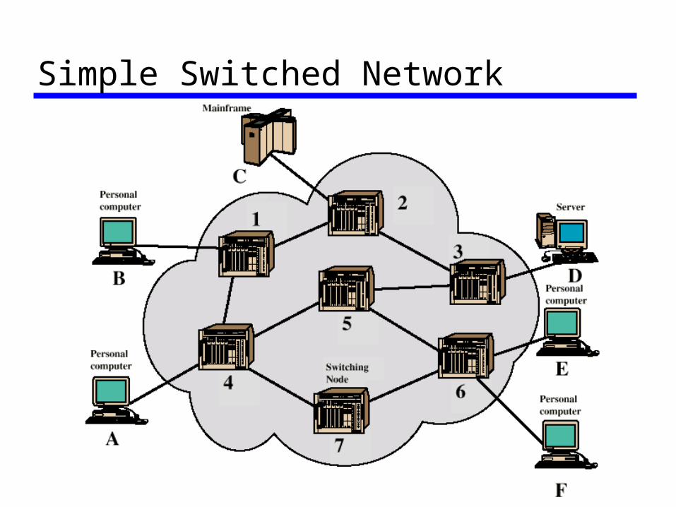
Simple Switched Network

Circuit Switching Dedicated communication path between
two stations Three phases
Establish Transfer Disconnect
Must have switching capacity and channel capacity to establish connection
Must have intelligence to work out routing
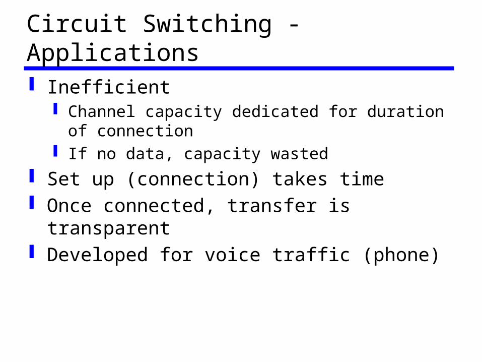
Circuit Switching - Applications Inefficient
Channel capacity dedicated for duration of connection
If no data, capacity wasted Set up (connection) takes time Once connected, transfer is transparent Developed for voice traffic (phone)
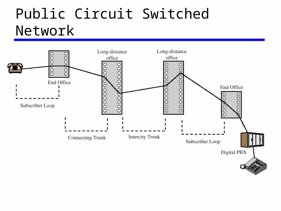
Public Circuit Switched Network
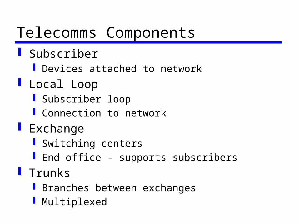
Telecomms Components Subscriber
Devices attached to network Local Loop
Subscriber loop Connection to network
Exchange Switching centers End office - supports subscribers
Trunks Branches between exchanges Multiplexed
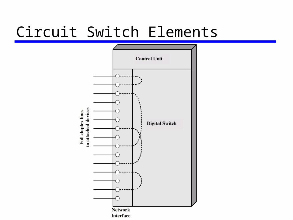
Circuit Switch Elements
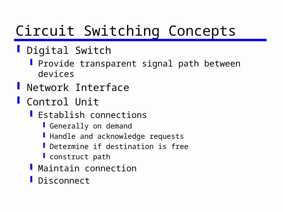
Circuit Switching Concepts Digital Switch
Provide transparent signal path between devices Network Interface Control Unit
Establish connections Generally on demand Handle and acknowledge requests Determine if destination is free construct path
Maintain connection Disconnect

Blocking or Non-blocking Blocking
A network is unable to connect stations because all paths are in use
A blocking network allows this Used on voice systems
Short duration calls
Non-blocking Permits all stations to connect (in pairs) at
once Used for some data connections
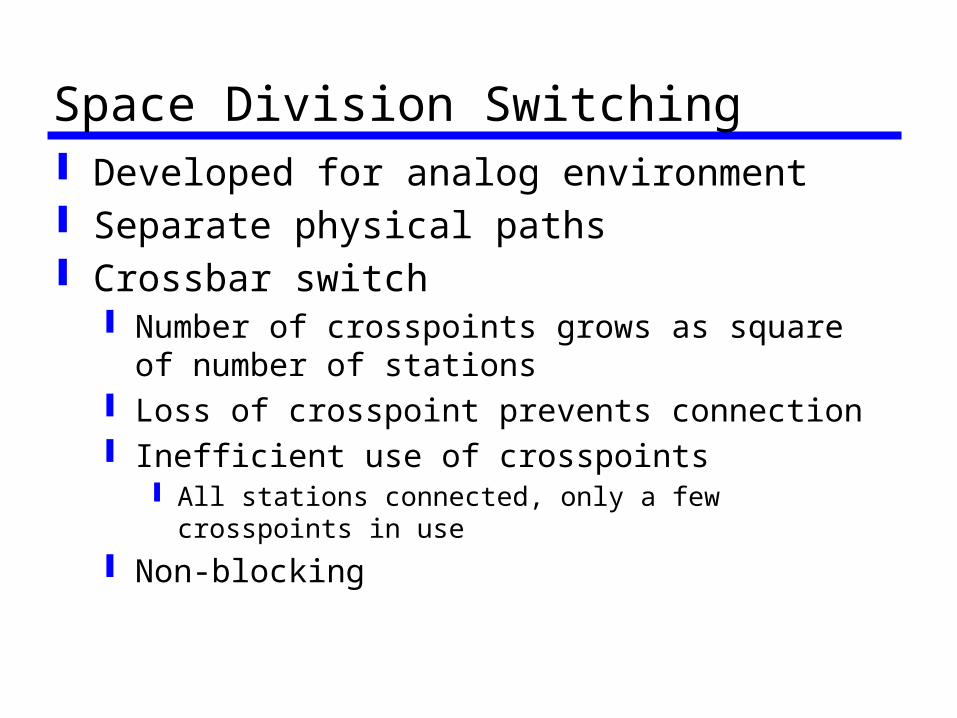
Space Division Switching Developed for analog environment Separate physical paths Crossbar switch
Number of crosspoints grows as square of number of stations
Loss of crosspoint prevents connection Inefficient use of crosspoints
All stations connected, only a few crosspoints in use
Non-blocking

Crossbar Matrix
Multistage Switch Reduced number of crosspoints More than one path through network
Increased reliability More complex control May be blocking
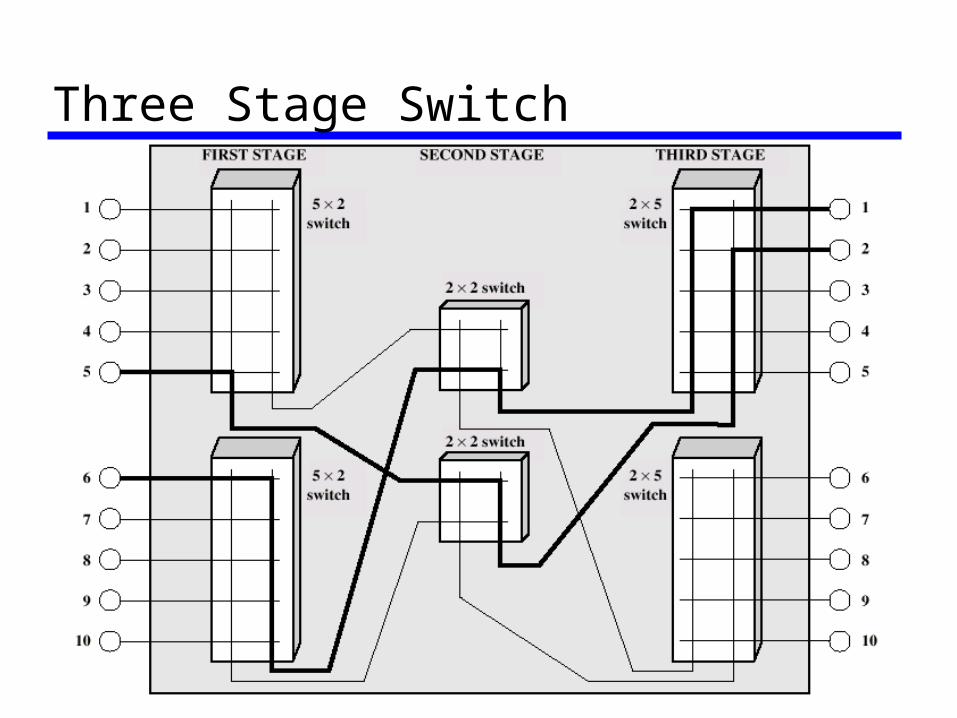
Three Stage Switch

Time Division Switching Partition low speed bit stream into pieces
that share higher speed stream e.g. TDM bus switching
based on synchronous time division multiplexing
Each station connects through controlled gates to high speed bus
Time slot allows small amount of data onto bus Another lines gate is enabled for output at the
same time
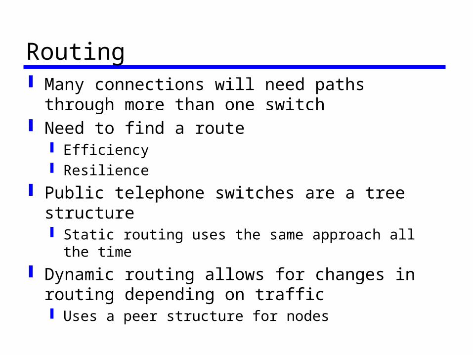
Routing Many connections will need paths through
more than one switch Need to find a route
Efficiency Resilience
Public telephone switches are a tree structure Static routing uses the same approach all the time
Dynamic routing allows for changes in routing depending on traffic Uses a peer structure for nodes
Alternate Routing Possible routes between end offices
predefined Originating switch selects appropriate
route Routes listed in preference order Different sets of routes may be used at
different times
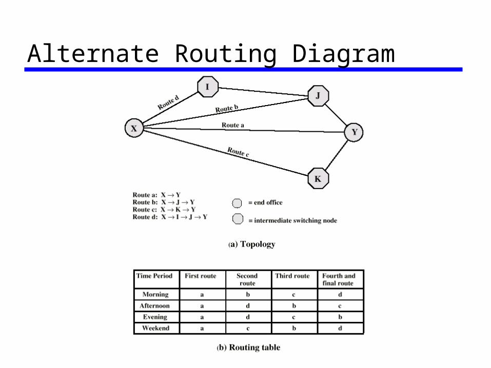
Alternate Routing Diagram
Principles of Packet switching Circuit switching designed for voice
Resources dedicated to a particular call Much of the time a data connection is idle Data rate is fixed
Both ends must operate at the same rate
Basic Operation Data transmitted in small packets
Typically 1000 octets Longer messages split into series of packets Each packet contains a portion of user data
plus some control info Control info
Routing (addressing) info Packets are received, stored briefly
(buffered) and past on to the next node Store and forward

Use of Packets
Advantages Line efficiency
Single node to node link can be shared by many packets over time
Packets queued and transmitted as fast as possible
Data rate conversion Each station connects to the local node at its own
speed Nodes buffer data if required to equalize rates
Packets are accepted even when network is busy Delivery may slow down
Priorities can be used
Switching Technique Station breaks long message into packets Packets sent one at a time to the network Packets handled in two ways
Datagram Virtual circuit
Datagram Each packet treated independently Packets can take any practical route Packets may arrive out of order Packets may go missing Up to receiver to re-order packets and
recover from missing packets
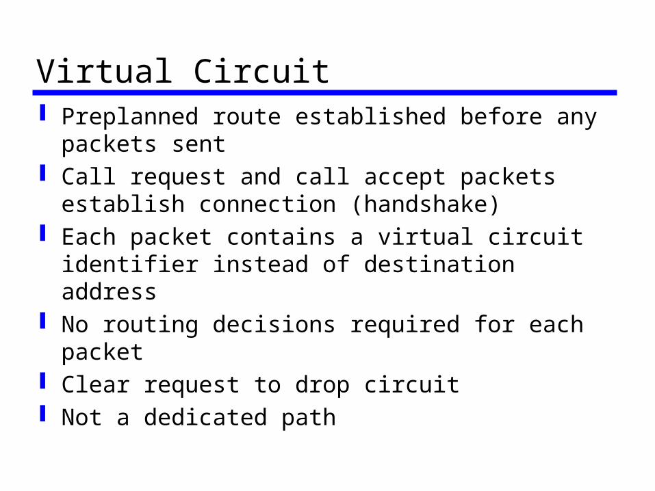
Virtual Circuit Preplanned route established before any
packets sent Call request and call accept packets
establish connection (handshake) Each packet contains a virtual circuit
identifier instead of destination address No routing decisions required for each
packet Clear request to drop circuit Not a dedicated path
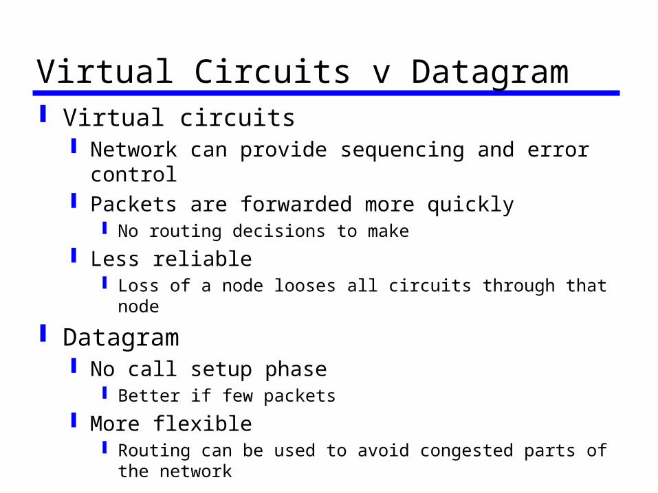
Virtual Circuits v Datagram Virtual circuits
Network can provide sequencing and error control
Packets are forwarded more quickly No routing decisions to make
Less reliable Loss of a node looses all circuits through that node
Datagram No call setup phase
Better if few packets
More flexible Routing can be used to avoid congested parts of the
network
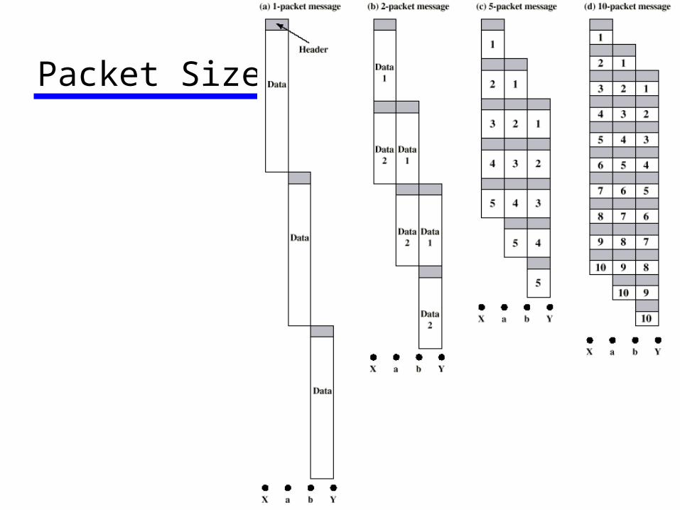
Packet Size
Circuit v Packet Switching Performance
Propagation delay Transmission time Node delay
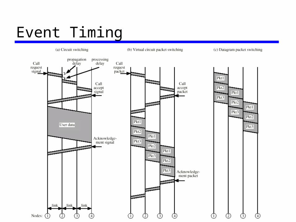
Event Timing
External and Internal Operation Packet switching - datagrams or virtual
circuits Interface between station and network
node Connection oriented
Station requests logical connection (virtual circuit) All packets identified as belonging to that connection &
sequentially numbered Network delivers packets in sequence External virtual circuit service e.g. X.25 Different from internal virtual circuit operation
Connectionless Packets handled independently External datagram service Different from internal datagram operation

Combinations (1) External virtual circuit, internal virtual
circuit Dedicated route through network
External virtual circuit, internal datagram Network handles each packet separately Different packets for the same external virtual
circuit may take different internal routes Network buffers at destination node for re-
ordering

Combinations (2) External datagram, internal datagram
Packets treated independently by both network and user
External datagram, internal virtual circuit External user does not see any connections External user sends one packet at a time Network sets up logical connections

External Virtual Circuit andDatagram Operation
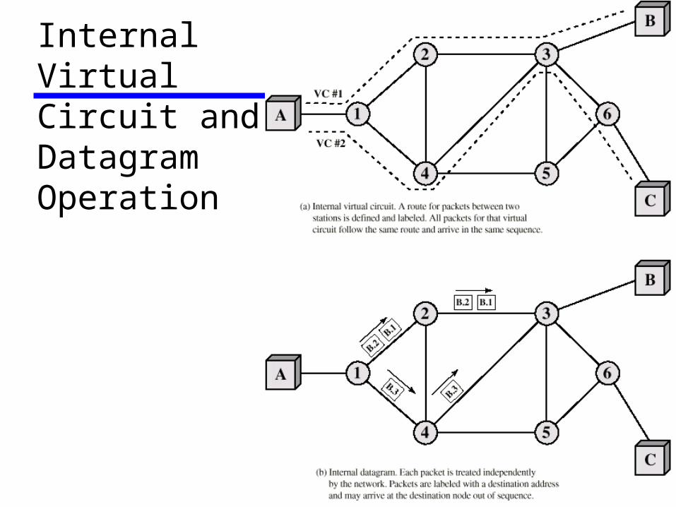
InternalVirtualCircuit andDatagram Operation
Routing Complex, crucial aspect of packet
switched networks Characteristics required
Correctness Simplicity Robustness Stability Fairness Optimality Efficiency
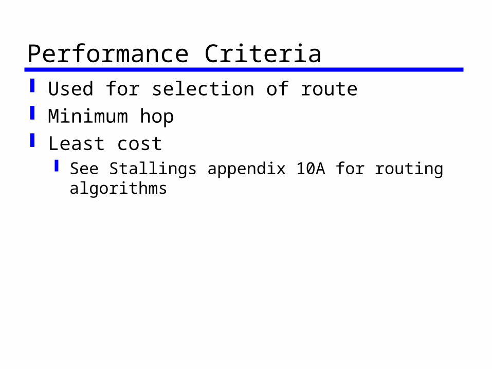
Performance Criteria Used for selection of route Minimum hop Least cost
See Stallings appendix 10A for routing algorithms
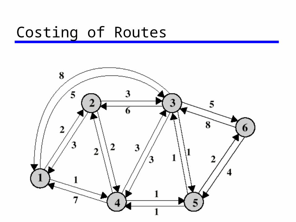
Costing of Routes
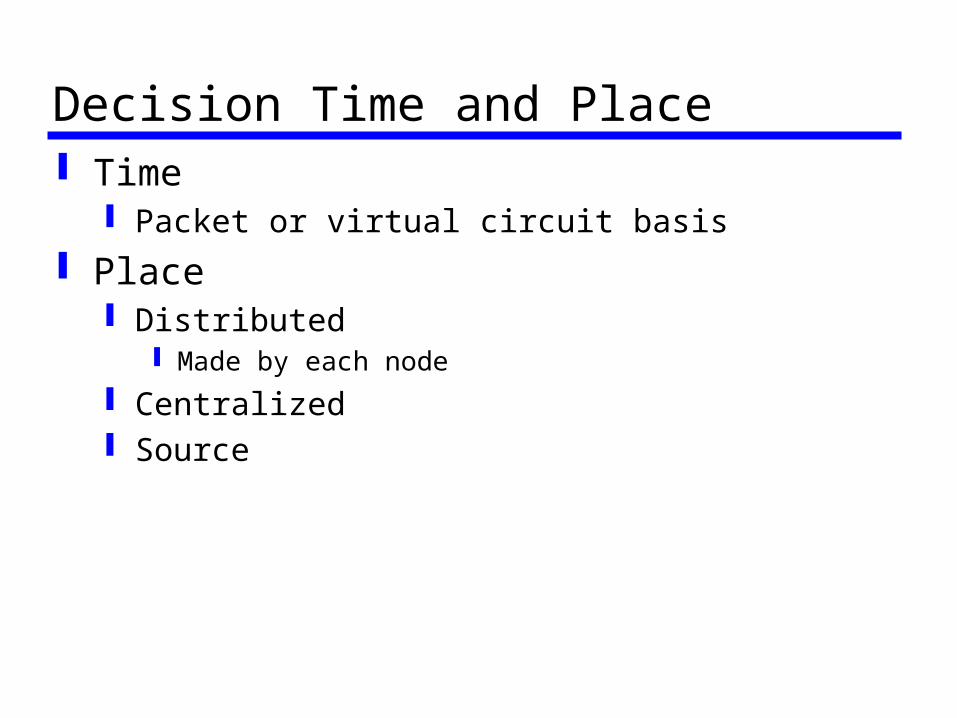
Decision Time and Place Time
Packet or virtual circuit basis Place
Distributed Made by each node
Centralized Source
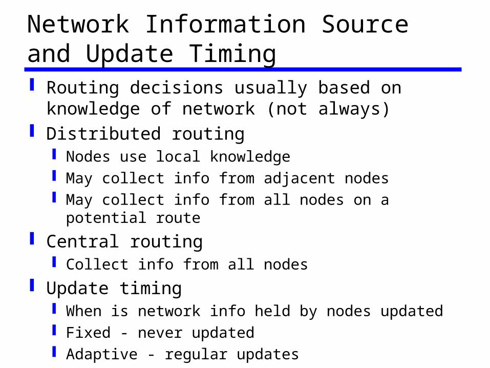
Network Information Source and Update Timing Routing decisions usually based on
knowledge of network (not always) Distributed routing
Nodes use local knowledge May collect info from adjacent nodes May collect info from all nodes on a potential
route Central routing
Collect info from all nodes Update timing
When is network info held by nodes updated Fixed - never updated Adaptive - regular updates
Routing Strategies Fixed Flooding Random Adaptive
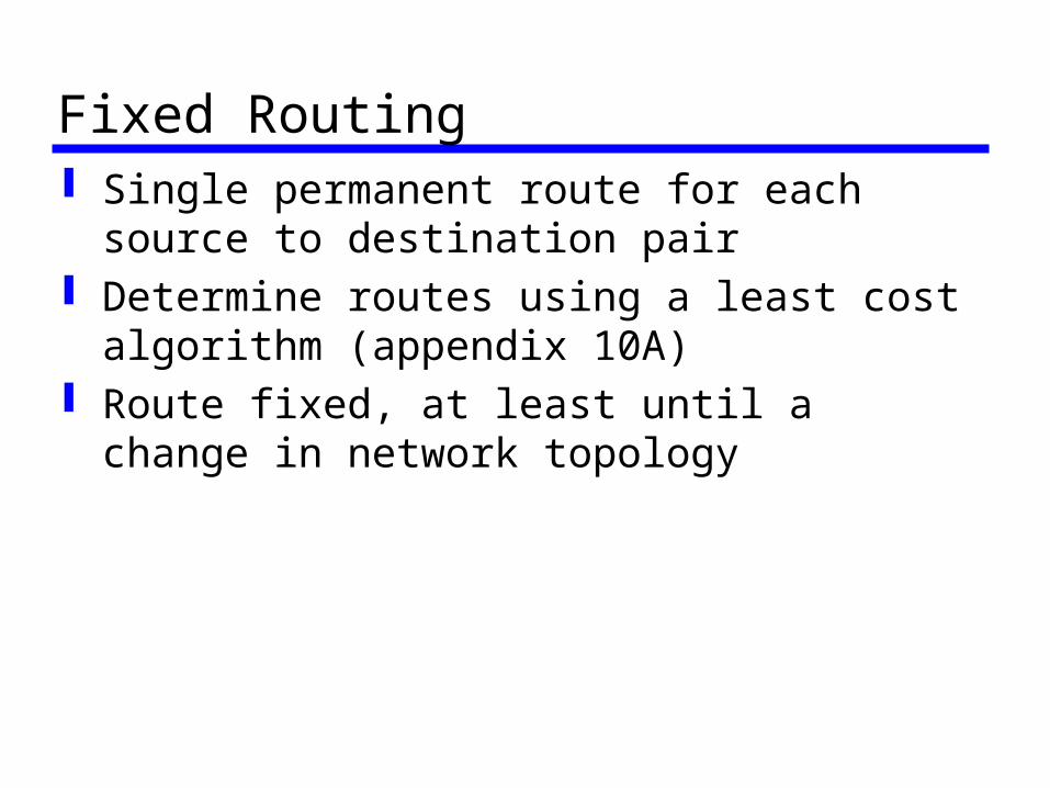
Fixed Routing Single permanent route for each source to
destination pair Determine routes using a least cost
algorithm (appendix 10A) Route fixed, at least until a change in
network topology
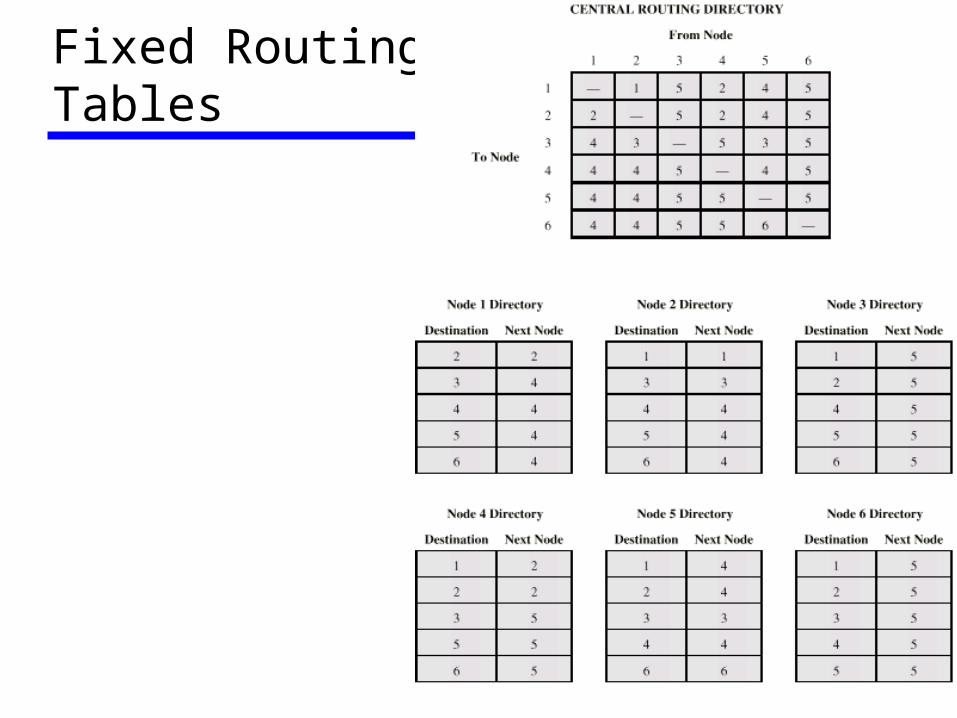
Fixed RoutingTables
Flooding No network info required Packet sent by node to every neighbor Incoming packets retransmitted on every
link except incoming link Eventually a number of copies will arrive
at destination Each packet is uniquely numbered so
duplicates can be discarded Nodes can remember packets already
forwarded to keep network load in bounds Can include a hop count in packets
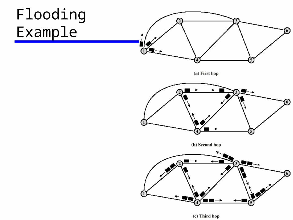
Flooding Example
Properties of Flooding All possible routes are tried
Very robust At least one packet will have taken
minimum hop count route Can be used to set up virtual circuit
All nodes are visited Useful to distribute information (e.g. routing)
Random Routing Node selects one outgoing path for
retransmission of incoming packet Selection can be random or round robin Can select outgoing path based on
probability calculation No network info needed Route is typically not least cost nor
minimum hop
Adaptive Routing Used by almost all packet switching networks Routing decisions change as conditions on the
network change Failure Congestion
Requires info about network Decisions more complex Tradeoff between quality of network info and
overhead Reacting too quickly can cause oscillation Too slowly to be relevant
Adaptive Routing - Advantages Improved performance Aid congestion control (See chapter 12) Complex system
May not realize theoretical benefits
Classification Based on information sources
Local (isolated) Route to outgoing link with shortest queue Can include bias for each destination Rarely used - do not make use of easily available info
Adjacent nodes All nodes
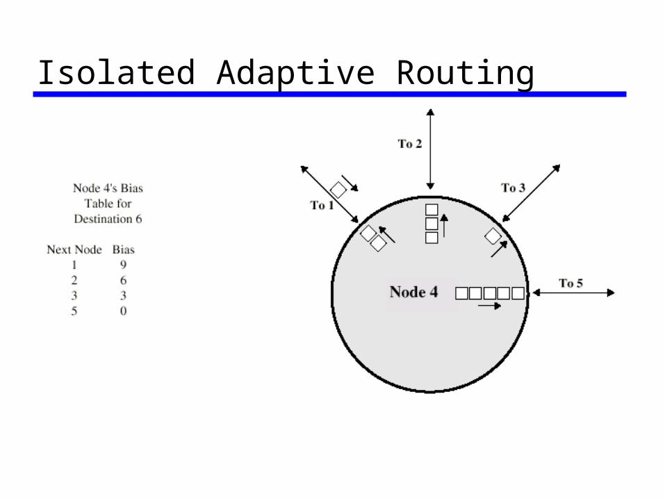
Isolated Adaptive Routing
ARPANET Routing Strategies(1) First Generation
1969 Distributed adaptive Estimated delay as performance criterion Bellman-Ford algorithm (appendix 10a) Node exchanges delay vector with neighbors Update routing table based on incoming info Doesn't consider line speed, just queue length Queue length not a good measurement of
delay Responds slowly to congestion

ARPANET Routing Strategies(2) Second Generation
1979 Uses delay as performance criterion Delay measured directly Uses Dijkstras algorithm (appendix 10a) Good under light and medium loads Under heavy loads, little correlation between
reported delays and those experienced
ARPANET Routing Strategies(3) Third Generation
1987 Link cost calculations changed Measure average delay over last 10 seconds Normalize based on current value and
previous results
Required Reading Stallings chapters 9 and 10 ITU-T web site Telephone company web sites (not much
technical info - mostly marketing)