Embed Size (px)
Citation preview

THE HONG KONG POLYTECHNIC UNIVERSITY
DEPARTMENT OF ELECTRICAL ENGINEERING
Project ID: PT_FYP_24
Induction Motor Protection System
by
Leung Ka Ho
14122373D
Final Report
Bachelor of Engineering (Honours)
in
Electrical Engineering
Of
The Hong Kong Polytechnic University
Supervisor: Edward Lo Date: 11th
November, 2017

THE HONG KONG POLYTECHNIC UNIVERSITY
DEPARTMENT OF ELECTRICAL ENGINEERING
Abstract
Three-phase induction motors are commonly used for industrial, commercial or even
residential proposes. To achieve optimal operation of 3-phase induction motor, the
voltage of each phase should be equal. When abnormal voltages are supplied to the 3-
phase induction motor, the efficiency of the motor may be greatly reduced and the motor
may even be damaged. Therefore, a protection system is required to stop the 3-phase
induction motor when the mentioned abnormal conditions occurred.
The protection system mainly contains two parts: relay circuit and electronic circuit. In
relay circuit, 12VDC is supplying 4 nos. of 12VDC NC relays and 1 no. of 3CO NO relay
in series. 3 of 12VDC NC relays are for under-voltage & over-voltage detection of the
three phases and 1 of them is for overheating detection. Normally, the 3CO NO relay is
energized by 12VDC which links the connection between the 220VAC power source to
the three-phase induction motor. When under-voltage, over-voltage, single phasing or
overheating occurred, the corresponding NC relay would be energized and, therefore,
opens the circuit. Power would be stopped supplying to the load due to the de-energized
of 3CO NO relay. Another part is electronic circuit. Considering one of the phases,
220VAC is first stepped down to 12VAC by using a step-down transformer. The 12VAC
would then be converted to 12V DC as an input voltage and also regulated to 5VDC as a
DC voltage source. Op-amp is used as a comparator which compares the input voltage
with a pre-set voltage. The output would go high when the input voltage is out of
acceptable range, which leads to the saturation of transistor and finally energized the
12VDC corresponding NC relay. As for overheating detection, an NTC thermistor is
powered by the 5VDC voltage. The surrounding temperature of the thermistor would
affect its resistance, causing changes in input voltage.
Three 12V lamps are used to replace the 3-phase induction motor for simulation. A
variable resistor of each phase is adjusted in order to simulate the conditions of over-
voltage, under-voltage, single-phasing and over-heating. 220V±20% and 31°C of over-
heating temperature are chosen as the requirement in the simulation. As the input voltage
of comparator under stable and healthy voltage supply is 2.5V, the fault LED lamp of the
corresponding phase will light up when the input voltage is higher than 3.0V or lower
than 2.0V (2.5V±20%) and hence stop the motor immediately. Moreover, the input
voltage for overheating detection is 2.8V, calculated by applying voltage divider. The
fault LED lamp of overheating will light up when the input voltage is higher than 2.8V.

THE HONG KONG POLYTECHNIC UNIVERSITY
DEPARTMENT OF ELECTRICAL ENGINEERING
Table of Content
1. Introduction --------------------------------------------------------------- P.1
2. Objective --------------------------------------------------------------- P.4
3. Background --------------------------------------------------------------- P.5
4. Methodology --------------------------------------------------------------- P.7
4a. Component used --------------------------------------------- P.9
Transformer --------------------------------------------- P.9
Relay ----------------------------------------------------- P.10
Full-wave Bridge Rectifier -------------------------- P.11
Voltage Regulator ----------------------------------- P.13
Op-amps -------------------------------------------- P.14
NOR Gate -------------------------------------------- P.17
Thermistor -------------------------------------------- P.18
Diode ----------------------------------------------------- P.19
Transistor (BJT) -------------------------------------------- P.20
Resistor ----------------------------------------------------- P.22
Variable Resistor -------------------------------------------- P.24
Capacitor ----------------------------------------------------- P.25
4b. Procedure ------------------------------------------------------ P.26
5. Simulation --------------------------------------------------------------- P.45
6. Discussion --------------------------------------------------------------- P.54
7. Conclusion --------------------------------------------------------------- P.55
8. Reference --------------------------------------------------------------- P.56
9. Appendix --------------------------------------------------------------- P.57

THE HONG KONG POLYTECHNIC UNIVERSITY
DEPARTMENT OF ELECTRICAL ENGINEERING
1
1. Introduction
This project aimed to design a protection system of an induction motor to protect a 3-phase
induction motor under conditions including under-voltage, over-voltage, single phasing and
over-temperature.
3-phase induction motors are commonly used for industrial, commercial or even
residential proposes. MCB (Miniature Circuit Breaker) is generally used to protect the
motor from over-current. However, it may not be enough to keep the motor operating in
good condition. When unbalanced voltage is supplied to the motor, the torque and speed
of the motor would be affected. The motor may also be overheated when the ambient
temperature is too high. All the above conditions may lead to reduced efficiency or even
damaged motor. Therefore, protection system is important for three-phase induction
motor.

THE HONG KONG POLYTECHNIC UNIVERSITY
DEPARTMENT OF ELECTRICAL ENGINEERING
2
The 3-phase induction motor protection system can be divided in 2 parts: The Electronics
Circuit and The Relay Circuit:
Fig.1 Block Diagram of Induction Motor Protection System

THE HONG KONG POLYTECHNIC UNIVERSITY
DEPARTMENT OF ELECTRICAL ENGINEERING
3
The basic operation of this protection system is to stop supplying power to the motor
immediately in the case of under-voltage, over-voltage, single phasing and overheating of
motor. The supply voltage is stepped down and rectified for an electronic circuit and a relay
circuit. The rectified voltage is further regulated to be a DC voltage source for electronics
circuit. The electronics circuit mainly compares the input voltages from the three phases
and thermistor with pre-set voltages. It would give signals to relay circuit if any of the input
voltages are out of expected ranges. The relay circuit directly controls the voltage supply of
the induction motor. It would cut of the supply to the induction motor when signal from the
electronic circuit received.

THE HONG KONG POLYTECHNIC UNIVERSITY
DEPARTMENT OF ELECTRICAL ENGINEERING
4
2. Objective
Cut off the power supply to the induction motor when:
- Under-voltage
- Over-voltage
- Single-phasing
- Overheating
Same voltage source used for supplying both the motor and the protection system
Customizable upper-limit and lower-limit of voltage supply
Customizable upper-limit of operating temperature

THE HONG KONG POLYTECHNIC UNIVERSITY
DEPARTMENT OF ELECTRICAL ENGINEERING
5
3. Background
As a three-phase induction motor, all the three phases have to be supplied by balanced
voltages to achieve optimal operation. When one of the phases is missing, the voltages will
be unbalanced. William H. Kersting has concluded that single-phasing may be happened
due to blown fuse or activated protective device on one of the phase of the motor [1]. The
motor will keep operating when it is without any protection system [1]. Overheat of motor
will be occurred when the voltages are unbalanced. Moreover, the efficiency of the motor
is greatly reduced when the terminal voltages are single phased because there is a lot of
energy converted into heat instead of power. The motor may also be damaged if the
operation of the motor is not stopped immediately. It may also lead to extra load and
further cause additional electricity charges [2]. In addition, there might be some abnormal
conditions of power supply which causing the voltage supplied to the motor is out of the
expected range while no phases are missing. It is found that different kinds of serious
problems may be occurred if protection system did not apply to an induction motor.
Fig. 2 A typical automatic circuit reclosers

THE HONG KONG POLYTECHNIC UNIVERSITY
DEPARTMENT OF ELECTRICAL ENGINEERING
6
Regarding single-phasing, automatic circuit reclosers are widely applied in distribution
system [3]. It recloses the circuit after instant transient voltage or stops the voltage supply
when the detected voltage keeps abnormal after a number of retries. The automatic circuit
recloser requires less maintenance and avoid single-phasing of the voltage supply.
Compare the recloser with the designed protection system of this report, the recloser is
more expensive and space-occupying. It is also dangerous when a person is touching the
circuit [4]. Moreover, automatic circuit reclosers are usually used at overhead lines which
focus on a distribution system. It may not be necessary to apply if only an induction motor
is focused on. Therefore, a simple, cost-effective, small-sized induction motor protection
system is required to protect an induction motor independently.

THE HONG KONG POLYTECHNIC UNIVERSITY
DEPARTMENT OF ELECTRICAL ENGINEERING
7
4. Methodology
The electrical circuit design of the induction motor protection system is shown below:
Fig.3 Electrical Circuit Design for Induction Motor Protection System

THE HONG KONG POLYTECHNIC UNIVERSITY
DEPARTMENT OF ELECTRICAL ENGINEERING
8
The protection system mainly contains two parts: relay circuit and electronics circuit. In
relay circuit, 12VDC is supplying 4 nos. of 12VDC NC relays and 1 no. of 3CO NO relay
in series. 3 of the 12VDC NC relays are for under-voltage & over-voltage detection of the
three phases and 1 of them is for overheating detection. In normal situation, the 3CO NO
relay is energized by 12VDC which links the connection between the 220VAC power
source to the three-phase induction motor. When under-voltage, over-voltage, single
phasing or overheating occurred, the corresponding NC relay would be energized and,
therefore, opens the circuit. Power would be stopped supplying to the load due to the de-
energized of 3CO NO relay.
Another part is electronic circuit. Considering one of the phases, 220VAC is first stepped
down to 12VAC by using a step-down transformer. The 12VAC would then be converted
to 12V DC by full-wave bridge rectifier as an input voltage and also regulated to 5VDC
by a voltage regulator as a DC voltage source. Op-amp is used as a comparator which
compares the input voltage with a pre-set voltage. Regarding L1, L2 and L3, the output of
the comparator would go low when the input voltage is out of acceptable range and then
inverted to high by a NOR gate. As for overheating detection, an NTC thermistor is
powered by the 5VDC voltage. The surrounding temperature of the thermistor would
affect its resistance, causing changes in input voltage. The output of the comparator
would go high directly when the input voltage is higher than the pre-set voltage. Any
outputs will lead to the saturation of the corresponding transistor and finally energized the
corresponding 12VDC NC relay.

THE HONG KONG POLYTECHNIC UNIVERSITY
DEPARTMENT OF ELECTRICAL ENGINEERING
9
4a. Component Used
Transformer
Transformer is an electrical device which uses electromagnetic induction for voltage
change. It normally consists of 2 windings. The voltage ratio is directly proportional to the
ratio of winding turns.
Fig.4 A general transformer Fig.5 Basic circuit of transformer

THE HONG KONG POLYTECHNIC UNIVERSITY
DEPARTMENT OF ELECTRICAL ENGINEERING
10
Relay
Relay is an electrical switch which closes or opens a circuit by using electro-magnet. The
figure below shows an NC relay which normally opened when the relay is not powered.
When enough voltage is supplied to coil terminals, the energized electro-magnet would
attract the armature and hence forcing the common contact switches its position and touch
the NO contact.
Fig.6 General relay Fig.7 Basic circuit of an NC relay
Fig.8 Structure of an NC relay Fig.9 Types of Relay
Normally, relays are described in XPYT, where X refers to number of poles and Y refers to
number of throws.

THE HONG KONG POLYTECHNIC UNIVERSITY
DEPARTMENT OF ELECTRICAL ENGINEERING
11
Full-wave Bridge Rectifier
Full-wave bridge rectifier consists of 4 diodes which build a bridge and convert full AC
input voltage into DC voltage.
Fig.10 W06M full-wave bridge rectifier Fig.11 Structure of a full-wave bridge rectifier
In the above full-wave bridge rectifier, 2 legs signed “~” are the AC input terminal while
another two legs with positive sign and negative sign are the DC output terminal.
Fig.12a One of the direction of current Fig. 12b Another direction of current
flow of a full-wave bridge rectifier flow of a full-wave bridge rectifier
No matter the direction of the input current flow, the output direction remains unchanged.

THE HONG KONG POLYTECHNIC UNIVERSITY
DEPARTMENT OF ELECTRICAL ENGINEERING
12
However, the output waveform is not smoothed after rectified. Capacitor is usually added
after a rectifier to smoothen the voltage.
Fig.13 The waveform of input voltage, output voltage and output voltage after a
smoothing capacitor of a full-wave bridge rectifier

THE HONG KONG POLYTECHNIC UNIVERSITY
DEPARTMENT OF ELECTRICAL ENGINEERING
13
Voltage Regulator
Voltage Regulator is used to turn an input voltage into a constant voltage.
It can be used as a voltage stabilizer and used for electronics devices which required 5VDC
source to activate.
Fig.15 General Circuit of a voltage regulator
Fig.14 7805 Voltage Regulator

THE HONG KONG POLYTECHNIC UNIVERSITY
DEPARTMENT OF ELECTRICAL ENGINEERING
14
Op-amp
Op-amp (Operational amplifier) normally used to output a voltage based on the differences
between two input terminals.
Fig.16 Symbol of an op-amp
Ideally, the two inputs are connected with an infinite resistance of resistor in series. It
means that no currents are flowing into the input terminal in ideal situation. Therefore, it
basically only takes the voltage differences between the two inputs to give corresponding
output.

THE HONG KONG POLYTECHNIC UNIVERSITY
DEPARTMENT OF ELECTRICAL ENGINEERING
15
The following circuit shows a simply circuit of comparator. The positive side is the
reference voltage while the negative side is the input voltage. When the voltage on positive
side is higher than the voltage on negative side, +V will be the output voltage. Oppositely,
when the voltage on positive side is lower than the voltage on negative side, -V will be the
output voltage.
Fig.17 Basic circuit of a comparator
There is a variable resistor on the positive input so the reference voltage can be adjusted by
applying voltage divider:
Fig.18 Concept of voltage divider

THE HONG KONG POLYTECHNIC UNIVERSITY
DEPARTMENT OF ELECTRICAL ENGINEERING
16
Voltage across R2 = Input voltage x R1/(R1+R2)
Normally, comparators are installed in ICs (Integrated Circuits) such as LM339N.
LM339N are commonly used IC which contains 4 nos. of comparators.
Fig.19 LM339N Quad Comparator Fig.20 Structure of a LM339N Quad Comparator
All the four comparators can be operated after voltage is supplied to the IC through
terminals 3 and 12.

THE HONG KONG POLYTECHNIC UNIVERSITY
DEPARTMENT OF ELECTRICAL ENGINEERING
17
NOR Gate
NOR gate is a digital component which outputs high only when both the inputs are high.
Fig. 21 Symbol and truth table of NOR gate
It can be used as an NOT gate if the same input goes to both terminal A and B. Similar to
comparators, NOR gates are generally installed in ICs such as 74HC02 Quad NOR gate.
THE HONG KONG POLYTECHNIC UNIVERSITY
DEPARTMENT OF ELECTRICAL ENGINEERING
18
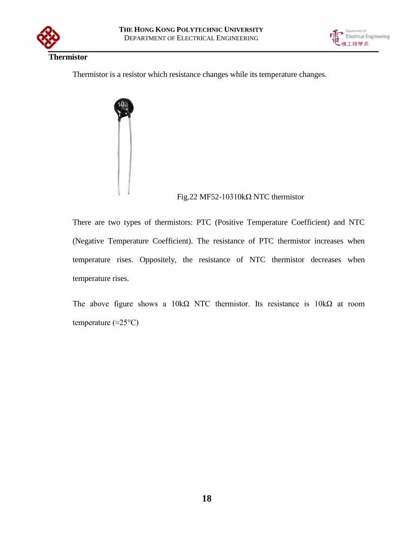
Thermistor
Thermistor is a resistor which resistance changes while its temperature changes.
Fig.22 MF52-10310kΩ NTC thermistor
There are two types of thermistors: PTC (Positive Temperature Coefficient) and NTC
(Negative Temperature Coefficient). The resistance of PTC thermistor increases when
temperature rises. Oppositely, the resistance of NTC thermistor decreases when
temperature rises.
The above figure shows a 10kΩ NTC thermistor. Its resistance is 10kΩ at room
temperature (≈25°C)

THE HONG KONG POLYTECHNIC UNIVERSITY
DEPARTMENT OF ELECTRICAL ENGINEERING
19
Diode
Diode is an electronic element which current can only pass through it in one direction only.
When current are flowing in reversed direction, the diode will form a barrier and block the
current.
Fig.23 IN4007 Diode
Basically, the P-type material contains electron holes while the N-type material contains
electrons. The two materials touch together and form a depletion layer at PN-junction.
When positvie voltage is applied to the anode of the diode and negatvie voltage is applied
to the cathode of the diode, current can be passed through the diode if the voltage
difference is high enough(≈0.7v) to comeover the PN-junction. When the direction of the
applied voltage inversed, the depletion layer of PN-junction becomes thicker and block the
current.
Fig.24 Basic structure of a diode

THE HONG KONG POLYTECHNIC UNIVERSITY
DEPARTMENT OF ELECTRICAL ENGINEERING
20
Transistor (BJT)
Fig.25 BC547 Transistor Fig.26 Basic structure of a BJT transistor
Transistor is a semi-conductor which is normally used as an amplifier or a switching device.
The above figure shows an NPN type bipolar junction transistor (BJT) which has three
terminals: Base, Collector and Emitter.
Fig.27 Graph of Collector Current Ic versus Collector-emitter Voltage Vce of a BJT

THE HONG KONG POLYTECHNIC UNIVERSITY
DEPARTMENT OF ELECTRICAL ENGINEERING
21
Transistor can be used as a switch. When there is not enough current flowing into Base
terminal, it does not allow current flowing through from Collector to Emitter. However,
current can flow through from Collector to Emitter when there is enough current flowing
into Base terminal. Hence, the Base acts like a switch between Collector and Emitter.
Typically, the Base-Emitter saturation voltage of a BJT is around 0.7V.
Fig.28 Basic concept of a BJT as a switch

THE HONG KONG POLYTECHNIC UNIVERSITY
DEPARTMENT OF ELECTRICAL ENGINEERING
22
Resistor
When current passes through a resistor, power has been dissipated and voltage has been
dropped.
Fig.29 A general metal film resistor
Resistor is commonly used in electronics devices. It can be used for power dissipation,
voltage reduction or current limitation.

THE HONG KONG POLYTECHNIC UNIVERSITY
DEPARTMENT OF ELECTRICAL ENGINEERING
23
Generally, there is a color code printed on each resistor in order to identify its resistance
and tolerance. The first, second and third colors represent the first three digits of its
resistance. The forth colors represent the multiplier of the three digits. The fifth colors
represent the tolerance of the shown resistance.
Fig.30 Color code of a resistor

THE HONG KONG POLYTECHNIC UNIVERSITY
DEPARTMENT OF ELECTRICAL ENGINEERING
24
Variable Resistor
Variable resistor is similar to normal resistor while its resistance can be adjusted. For
example, the resistance of a 10k Ohm variable resistor can be adjusted between 0Ω to 10kΩ.
Fig.31 A 10kΩ variable resistor

THE HONG KONG POLYTECHNIC UNIVERSITY
DEPARTMENT OF ELECTRICAL ENGINEERING
25
Capacitor
Fig.32 A 470uF capacitor
When current flows into a capacitor, the capacitor stores the energy. Once the voltage of
the capacitor is higher than the connect circuit, the capacitor will discharge. It helps to
stabilize the voltage. It can also smooth the rectified voltage. Moreover, different sizes of
capacitor are able to filter different ranges of frequency so capacitors are commonly used
on electronic devices.

THE HONG KONG POLYTECHNIC UNIVERSITY
DEPARTMENT OF ELECTRICAL ENGINEERING
26
4b. Procedure
In order to simulate the abnormal conditions of voltage supply, the model of induction
Fig.33 Electrical Circuit of Induction Motor Protection System for simulation

THE HONG KONG POLYTECHNIC UNIVERSITY
DEPARTMENT OF ELECTRICAL ENGINEERING
27
motor protection system is built as follow:
There are some changes from the original design for simulation:-
1. 3 nos. of 12V lamp are used instead of a 3-phase induction motor.
2. 12VDC 3P NO Relay is used instead of a 3-phase C/O relay.
3. 220VAC voltage supply is used instead of 380VAC 3-phase voltage which the
220VAC is applying to each phase.
4. After the 220VAC voltage supply is stepped down to 12VAC, the 12VAC is applying
to the lamps in parallel.
5. A 1kΩ resistor is added in series to the lamps to limit the current.
6. The simulation of over-voltage, under-voltage and missing phase is performed by
adjusting the variable resistors VR1, VR4, VR7.

THE HONG KONG POLYTECHNIC UNIVERSITY
DEPARTMENT OF ELECTRICAL ENGINEERING
28
Component List
Component Model Quantity(nos.)
220/12VAC Transformer - 1
12VDC 2PDT Relay MY2-GS x1, MY2 x3 4
12VDC 4PDT Relay MY4N-J 1
Full-wave Bridge Rectifier W06M 3
Voltage Regulator LM7805 1
Quad Comparator LM339N 2
Quad NOR Gate 74HC02 2
10k NTC Thermistor 103 1
Diode 1N4007 11
Transistor BC547 4
10kΩ Resistor - 9
2.2kΩ Resistor - 8
1kΩ Resistor - 6
10kΩ Variable Resistor - 10
470uF Capacitor - 4
4700uF Capacitor - 1
LED Light Bulb 4
Table.1 Component List for Electrical Circuit of Induction Motor Protection System for
simulation

THE HONG KONG POLYTECHNIC UNIVERSITY
DEPARTMENT OF ELECTRICAL ENGINEERING
29
The following photo shows the model of induction motor protection system.
Fig.34 Model of Induction Motor Protection System

THE HONG KONG POLYTECHNIC UNIVERSITY
DEPARTMENT OF ELECTRICAL ENGINEERING
30
1. 220V AC is stepped down to 12V AC by transformer (see Fig.35).
Fig.35
2. 12V AC is then rectified to 12V DC by full-wave bridge rectifier. 470uF capacitor is
applied d after the rectifier to smooth the rectified voltage (see Fig.36).
Fig.36

THE HONG KONG POLYTECHNIC UNIVERSITY
DEPARTMENT OF ELECTRICAL ENGINEERING
31
3. All phases are combined together after the voltage is rectified and smoothed (see
Fig.37b).
Fig.37a Fig.37b
4. 12V DC is then regulated to 5V DC by voltage regulator (see Fig.38). The regulator
can keep operating if 1 or 2 phases are missing because all the phases are combined in
Fig.37.
Fig.38

THE HONG KONG POLYTECHNIC UNIVERSITY
DEPARTMENT OF ELECTRICAL ENGINEERING
32
5. 470uF and 4700uF capacitors are connected in parallel after the rectified in order to
stabilize the voltage and to filter the noise frequencies (see Fig.39).
Fig.39

THE HONG KONG POLYTECHNIC UNIVERSITY
DEPARTMENT OF ELECTRICAL ENGINEERING
33
6. 5VDC is applied to another input of the comparators through the middle variable
resistor VR2, VR5 and VR8 respectively. The pre-set upper-limit of the input voltage
can be set by adjusting those variable resistors. If the input voltage is higher than the
pre-set voltage, it should be regarded as over-voltage.
5VDC is applied to another input of the comparators through the right variable resistor
VR3, VR6 and VR9 respectively. The pre-set lower-limit of the input voltage can be
set by adjusting those variable resistors. If the input voltage is lower than the pre-set
voltage or the input voltage is even lost, it should be regarded as under-voltage.
The smoothed 12VDC of the three phases go to the inputs of the comparator through
the left variable resistor VR1, VR4 and VR7 respectively. Those variable resistors set
the initial input voltage when the supply voltage is stable and healthy. As both the pre-
set voltage for over-voltage and under-voltage are within the range of 0-5V, the initial
input voltage can be set to 2.5V. As a result, the maximum range of the input voltage
is ±100%.

THE HONG KONG POLYTECHNIC UNIVERSITY
DEPARTMENT OF ELECTRICAL ENGINEERING
34
Regarding one of the phases, the voltages passed through the left and middle
comparators are the inputs of the comparator for over-voltage (OV) while the voltages
passed through the left and right comparators are the inputs of another comparator for
under-voltage and single phasing (UV) (see Fig.41 & Fig.42).
Adjustment for
initial input voltage
Upper-limit
Adjustment for over-
voltage
Lower-limit
Adjustment for under-
voltage & single
phasing
Fig.40

THE HONG KONG POLYTECHNIC UNIVERSITY
DEPARTMENT OF ELECTRICAL ENGINEERING
35
Fig.41
Fig.42 Electrical circuit at Fig.41
OV UV
UV
OV

THE HONG KONG POLYTECHNIC UNIVERSITY
DEPARTMENT OF ELECTRICAL ENGINEERING
36
Both the comparators of each phase share the same output, the output would be
grounded and give 0V to the NOR gate when any outputs of comparators go low (see
Fig.43).
Fig.43
Therefore, the output state of comparator would be low when the over-voltage, under-
voltage or single phasing is detected. The output signals go to the BJT transistor after
inverted by NOR gates (see Fig.44).

THE HONG KONG POLYTECHNIC UNIVERSITY
DEPARTMENT OF ELECTRICAL ENGINEERING
37
Fig.44
The following table shows the results of the comparator output, let the acceptable
range of input voltage is be X±10%.
Input voltage
(V)
Output
from OV
Output
from UV
Final
Output
State
Output State
after NOR gate
0 High Low Low High
X-10% High Low Low High
X-5% High High High Low
X High High High Low
X+5% High High High Low
X+10% Low High Low High
Table.2 Final Output State of Comparator

THE HONG KONG POLYTECHNIC UNIVERSITY
DEPARTMENT OF ELECTRICAL ENGINEERING
38
In fact, the output state of the comparator would be as same as the output state after
NOR gate if the positive and negative inputs are switched:
Input voltage
(V)
Output
from OV
Output
from UV
Final
Output
State
0 Low High Low
X-10% Low High Low
X-5% Low Low Low
X Low Low Low
X+5% Low Low Low
X+10% High Low Low
Table.3 Table of Final Output State of comparator with switched input sides
Due to the fact that the output would be grounded when any outputs of comparators go
low, the output state always goes low. As a result, the two comparators cannot share
the same output in this situation.

THE HONG KONG POLYTECHNIC UNIVERSITY
DEPARTMENT OF ELECTRICAL ENGINEERING
39
7. As for overheating detection, a 10kΩ NTC thermistor is used to affect the input
voltage (see Fig.45). 5VDC is applied to the input of the comparator through the
thermistor. When ambient temperature rises, the resistance of the thermistor decreases
and thus increases the input voltage of the comparator.
Similarly, 5VDC is applied to another input of the comparators through the variable
resistor VR10. The pre-set upper-limit of the input voltage can be set by adjusting that
variable resistor. If the input voltage is higher than the pre-set voltage, it should be
regarded as overheating.
The output of the comparator will then go to the transistor without inverting the signal.
Fig.45

THE HONG KONG POLYTECHNIC UNIVERSITY
DEPARTMENT OF ELECTRICAL ENGINEERING
40
8. All the 4 outputs go to Base of the transistor. With the help of pull-up voltage (see
Fig.46), current can pass through the transistor from Collector to Emitter when the
output level is high.
Fig.46
Pull-up
Resistor

THE HONG KONG POLYTECHNIC UNIVERSITY
DEPARTMENT OF ELECTRICAL ENGINEERING
41
9. The combined 12VDC voltage at step3 also supplied to the relay circuit via the brown
and green wires indicated in Fig.47.
Fig.47
10. The corresponding LED lamp will light up after the transistor is powered for the
indication of fault(see Fig.48).
Fig.48

THE HONG KONG POLYTECHNIC UNIVERSITY
DEPARTMENT OF ELECTRICAL ENGINEERING
42
11. At the same time, the corresponding NC relay will also be powered due to the
saturation of transistor (see red arrows in Fig.49). The coil of the relay will be
energized and hence cut the current flowing to the 3-phase NO relay (which is 3C/O
relay in realistic system).
Fig.49
Current Flowing to
3-phase Relay

THE HONG KONG POLYTECHNIC UNIVERSITY
DEPARTMENT OF ELECTRICAL ENGINEERING
43
12. When there are no faults, current can pass through all the NC relays and energize the
coil of the 3-phase relay (see Fig.50). The corresponding yellow LED lamp will light
up for indication of no faults (see Fig.51).
Fig.50
Fig.51
Current Flowing to
3-phase Relay

THE HONG KONG POLYTECHNIC UNIVERSITY
DEPARTMENT OF ELECTRICAL ENGINEERING
44
Voltage source can then pass through the 3-phase relay and supply to the lamps (see
Fig.52).
Fig.52
Current flows from voltage source to the common terminal of 3-phase relay (Red arrow);
and current flows from NO terminal of 3-phase relay (Blue arrow)

THE HONG KONG POLYTECHNIC UNIVERSITY
DEPARTMENT OF ELECTRICAL ENGINEERING
45
5. Simulation
Procedure for Fault Simulation of Induction Motor Protection System
Requirement set:
-The acceptable range of voltage supplied to the load is 220V±20%.
-Regard as overheating when ambient temperature is higher than 31°C.
1) Check to see if the input voltage is stable and healthy.
2) Adjust the resistance of the left variable resistor so the voltage inputted to the
comparator is 2.5V (see Fig.53).
Fig.53
3) Adjust the resistance of the middle variable resistor so the voltage inputted to the
comparator is 2.5V x (1+20%) = 3.0V (see Fig.54).

THE HONG KONG POLYTECHNIC UNIVERSITY
DEPARTMENT OF ELECTRICAL ENGINEERING
46
Fig.54
4) Adjust the resistance of the right variable resistor so the voltage inputted to the
comparator is 2.5V x (1-20%) = 2.0V (see Fig.55).
Fig.55

THE HONG KONG POLYTECHNIC UNIVERSITY
DEPARTMENT OF ELECTRICAL ENGINEERING
47
5) After step4, the setting of the protection system is done. The system is currently
operating.
6) In order to simulate over-voltage, under-voltage, single phasing of the voltage supply,
the left variable resistor will be adjusted so that the voltage inputted to the comparator
is higher than 3.0V (Fig.56), lower than 2.0V (Fig.57) and 0V (Fig.58) respectively.
The red LED lamp lights up for the fault indication of L1.
Fig.56
Fig.57

THE HONG KONG POLYTECHNIC UNIVERSITY
DEPARTMENT OF ELECTRICAL ENGINEERING
48
Apply the simulation in step 6 to L2 and L3. The yellow and blue LED lamps light up
for the fault indication of L2 and L3 respectively:-
Fig.58
Fig.59

THE HONG KONG POLYTECHNIC UNIVERSITY
DEPARTMENT OF ELECTRICAL ENGINEERING
49
Fig.60
Fig.61

THE HONG KONG POLYTECHNIC UNIVERSITY
DEPARTMENT OF ELECTRICAL ENGINEERING
50
Fig.62
Fig.63

THE HONG KONG POLYTECHNIC UNIVERSITY
DEPARTMENT OF ELECTRICAL ENGINEERING
51
7) Try out different combination of faults to check whether the system is working well.
The following figure (Fig.65) shows one of the situations when under-voltage occurred
in L2 and over-voltage occurred in L3 at the same time.
Fig.64
Fig.65

THE HONG KONG POLYTECHNIC UNIVERSITY
DEPARTMENT OF ELECTRICAL ENGINEERING
52
8) As for overheating simulation, the expected input voltage is 2.5V which is the voltage
when the system is placed at room temperature (≈25°C). The actual input voltage is
2.57V which is so close to 2.5V (see Fig.66).
9) By checking the table of the using thermistor resistance related to its temperature (see
Table.4), the thermistor resistance is around 7.86kΩat 31°C.
Table.4 Thermistor Resistance versus Temperature
Fig.66

THE HONG KONG POLYTECHNIC UNIVERSITY
DEPARTMENT OF ELECTRICAL ENGINEERING
53
The theoretical value of the input voltage at 31°C can then be calculated by applying the
formula of voltage divider:
5 ×10
7.8608 + 10= 2.799 ≈ 2.8𝑉
As a result, the corresponding variable resistor is adjusted so the voltage inputted to the
comparator is 2.8V (see Fig.67)
10) As typical body temperature is higher than 31°C, it should be regarded as overheating
after the thermistor is touched with fingertips for a few second (see Fig.68).
End of Simulation
Fig.67
Fig.68

THE HONG KONG POLYTECHNIC UNIVERSITY
DEPARTMENT OF ELECTRICAL ENGINEERING
54
6. Discussion
This induction motor protection system is customizable, small in size, cost-effective,
electrically safe and voltage re-applying available. Users can adjust the pre-set voltage for
over-voltage, under-voltage and over-heating to fit their needs. The system size is relatively
small to an induction motor. The components are not expensive while the system can be
operated effectively. The system design is safe which the motor will be stopped when the
system is not operated due to faults. Also, the voltage supply can automatically re-apply to
the motor after faults disappeared.
However, it may have some disadvantages such as short lifetime, unstable and relatively
low accuracy. The lifetime of the electronic devices is short so maintenance is required.
Also, it may not be suitable for motors or equipment which required very high accuracy of
protection system. The relay would bounce rapidly when the inputs difference of a
comparator is too small. Therefore, it is recommended that a timer relay can be applied to
the induction motor to avoid the impacts to the motor due to the bouncing of relay.

THE HONG KONG POLYTECHNIC UNIVERSITY
DEPARTMENT OF ELECTRICAL ENGINEERING
55
7. Conclusion
To conclude, this is a customizable induction motor protection system which is able to
protect the motor from over-voltage, under-voltage, single-phasing and overheating
effectively. However, it may not be suitable for motors or equipment which required very
high accuracy of voltage monitoring. A timer relay may be required to be applied to the
motor to avoid the impacts to the motor due to the bouncing of relay when the inputs
difference of a comparator is too small.
End of Report

THE HONG KONG POLYTECHNIC UNIVERSITY
DEPARTMENT OF ELECTRICAL ENGINEERING
56
8. Reference
[1] W. H. Kersting, “Causes and effects of single-phasing induction motors,” IEEE
Transactions on Industry Applications, vol. 41, no. 6, pp. 1499-1505, Nov. 2005.
[2] C.Y. Lee, “Effects of unbalanced voltage on the operation performance of a three-
phase induction motor,” IEEE Transactions on Energy Conversion, vol. 14, no. 2, pp.
202-208, Jun. 1999.
[3] E. B. Agamloh, S. Peele and J. Grappe, “Induction motor single-phasing performance
under distribution feeder recloser operations,” IEEE Transactions on Industry
Applications, vol. 50, no. 2, pp. 1568-576, Mar. 2014.
[4] J. D. Glover, M. S. Sarma and T. Overbye, Power System Analysis & Design.
Cengage Learning, 2011

THE HONG KONG POLYTECHNIC UNIVERSITY
DEPARTMENT OF ELECTRICAL ENGINEERING
57
9. Appendix
Appendix1. Datasheet of MY2 Relay

THE HONG KONG POLYTECHNIC UNIVERSITY
DEPARTMENT OF ELECTRICAL ENGINEERING
58

THE HONG KONG POLYTECHNIC UNIVERSITY
DEPARTMENT OF ELECTRICAL ENGINEERING
59
Appendix2. Datasheet of MY2-GS Relay

THE HONG KONG POLYTECHNIC UNIVERSITY
DEPARTMENT OF ELECTRICAL ENGINEERING
60

THE HONG KONG POLYTECHNIC UNIVERSITY
DEPARTMENT OF ELECTRICAL ENGINEERING
61

THE HONG KONG POLYTECHNIC UNIVERSITY
DEPARTMENT OF ELECTRICAL ENGINEERING
62

THE HONG KONG POLYTECHNIC UNIVERSITY
DEPARTMENT OF ELECTRICAL ENGINEERING
63
Appendix3. Datasheet of W06M Full-wave Bridge Rectifier

THE HONG KONG POLYTECHNIC UNIVERSITY
DEPARTMENT OF ELECTRICAL ENGINEERING
64
Appendix4. Datasheet of 7805 Voltage Regulator

THE HONG KONG POLYTECHNIC UNIVERSITY
DEPARTMENT OF ELECTRICAL ENGINEERING
65
Appendix.5 Datasheet of LM339N Quad Comparator

THE HONG KONG POLYTECHNIC UNIVERSITY
DEPARTMENT OF ELECTRICAL ENGINEERING
66
Appendix.6 Datasheet of 74HC02 Quad 2-Input NOR Gate

THE HONG KONG POLYTECHNIC UNIVERSITY
DEPARTMENT OF ELECTRICAL ENGINEERING
67
Appendix.7 Table of MF52-103 Thermistor Resistance Rated to Temperature

THE HONG KONG POLYTECHNIC UNIVERSITY
DEPARTMENT OF ELECTRICAL ENGINEERING
68

THE HONG KONG POLYTECHNIC UNIVERSITY
DEPARTMENT OF ELECTRICAL ENGINEERING
69
Appendix.8 Datasheet of 1N4007 Diode

THE HONG KONG POLYTECHNIC UNIVERSITY
DEPARTMENT OF ELECTRICAL ENGINEERING
70

THE HONG KONG POLYTECHNIC UNIVERSITY
DEPARTMENT OF ELECTRICAL ENGINEERING
71
Appendix.9 Datasheet of BC547 Bipolar Junction Transistor