Embed Size (px)
Citation preview

The Datapath
Andreas KlappeneckerCPSC321 Computer
Architecture

Administrative Issues WebCT: news, chat, grades
https://webct.tamu.edu Quantum Computing Seminar
Chance to make $356 Fair Scholarship in Telecommunications
$1000 for five qualified students in Computer Science or Comp. Eng. (CPSC)
Computer Science Logo Contest $1000 for best logo

Administrative Issues Talk by David Patterson
Friday, October 10, 4:10pm, HRBB 124
Project 0 due October 10 Exam, October 17 Invited Admissions for UGrads

Goal of this lecture Create a single datapath for
lw, sw beq (j later) add, sub, and, or, slt
Our line of attack We recall datapaths of these
operations and compose their datapaths

Instruction Word Formats
Register format
Immediate format
Jump format
op-code rs rt rd shamt functop-code rs rt rd shamt funct
op-code rs rt immediate valueop-code rs rt immediate value
op-code 26 bit current segment addressop-code 26 bit current segment address
6 5 5 16
6 5 5 5 5 6
6 26

Requirements of the Instruction Set
Memory Register file PC Sign extender ALU Add 4 to increase PC

Hardware components
PC
Instructionmemory
Instructionaddress
Instruction
a. Instruction memory b. Program counter
Add Sum
c. Adder
ALU control
RegWrite
RegistersWriteregister
Readdata 1
Readdata 2
Readregister 1
Readregister 2
Writedata
ALUresult
ALU
Data
Data
Registernumbers
a. Registers b. ALU
Zero5
5
5 3
16 32Sign
extend
b. Sign-extension unit
MemRead
MemWrite
Datamemory
Writedata
Readdata
a. Data memory unit
Address

Instruction Fetch + PC update

R-Format Instructions
Register format
op-code rs rt rd shamt functop-code rs rt rd shamt funct
6 5 5 5 5 6

Datapath for a load and store
1. register access 2. memory access calculation3. read or write from memory4. in the case of a load, write into register file

Marrying two Datapaths

Datapaths for Instruction Fetch, Memory and R-type Instructions
Note the added multiplexor switching between register 2 and sign-extended immediate value

Datapath for a Branch
Use ALU to evaluate the branch condition, another adder for
branch target = PC + 4 + (sign extended 16 bits)>>2

Marrying Branches with Rest
Output of Sign extend goes where?Output of PC adder goes where?
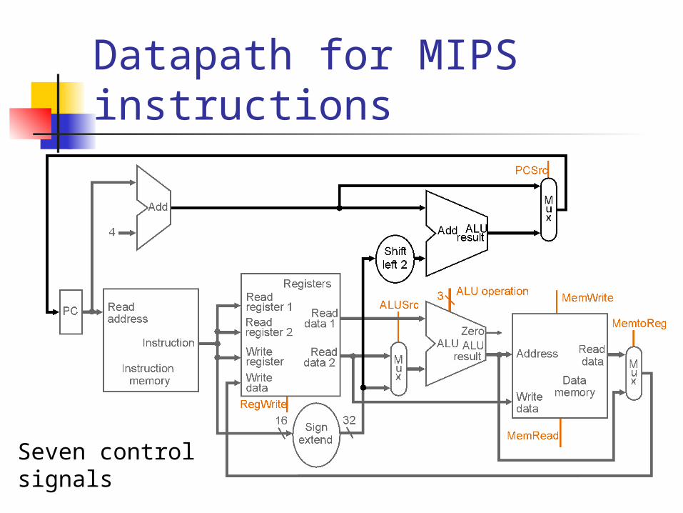
Datapath for MIPS instructions
Seven control signals

ALU Control For load and store instructions
Use ALU to compute memory address by addition (add immediate value)
For R-type instructions Perform addition, subtraction, and, or, slt value depends on 6bit function field
For beq perform subtraction

ALU Control Logic (Recall ALU)
ALU cntrl
Function
000 and
001 or
010 add
110 subtract
111 slt
Depending on instruction,the ALU has to perform one of the five operations

Must describe hardware to compute 3-bit ALU control input ALU control bits depend on ALUOp control bits and different functions codes for R-type
instructions
ALU Control
Instruction ALUOp Instruction Funct field Operationoperation ALUOp1 ALUOp0 Opcode F5 F4 F3 F2 F1 F0lw sw 0 0 lw/sw X X X X X X 010beq 0 1 beq X X X X X X 110add 1 X R-type X X 0 0 0 0 010sub 1 X R-type X X 0 0 1 0 110and 1 X R-type X X 0 1 0 0 000or 1 X R-type X X 0 1 0 1 001slt 1 X R-type X X 1 0 1 0 111

ALU Control
Operation2
Operation1
Operation0
Operation
ALUOp1
F3
F2
F1
F0
F (5– 0)
ALUOp0
ALUOp
ALU control block
Instruction ALUOp Instruction Funct field Operationoperation ALUOp1 ALUOp0 Opcode F5 F4 F3 F2 F1 F0lw sw 0 0 lw/sw X X X X X X 010beq 0 1 beq X X X X X X 110add 1 X R-type X X 0 0 0 0 010sub 1 X R-type X X 0 0 1 0 110and 1 X R-type X X 0 1 0 0 000or 1 X R-type X X 0 1 0 1 001slt 1 X R-type X X 1 0 1 0 111

Datapath for MIPS instructions
Note the seven control signals!

Generating Control Signals
R-format Iw sw beq
Op0
Op1
Op2
Op3
Op4
Op5
Inputs
Outputs
RegDst
ALUSrc
MemtoReg
RegWrite
MemRead
MemWrite
Branch
ALUOp1
ALUOpO
Opcode field of instruction yields control signals and ALUOp signals

Control
PC
Instructionmemory
Readaddress
Instruction[31– 0]
Instruction [20– 16]
Instruction [25– 21]
Add
Instruction [5– 0]
MemtoReg
ALUOp
MemWrite
RegWrite
MemRead
BranchRegDst
ALUSrc
Instruction [31– 26]
4
16 32Instruction [15– 0]
0
0Mux
0
1
Control
Add ALUresult
Mux
0
1
RegistersWriteregister
Writedata
Readdata 1
Readdata 2
Readregister 1
Readregister 2
Signextend
Shiftleft 2
Mux
1
ALUresult
Zero
Datamemory
Writedata
Readdata
Mux
1
Instruction [15– 11]
ALUcontrol
ALUAddress

Summary
Step nameAction for R-type
instructionsAction for memory-reference
instructionsAction for branches
Action for jumps
Instruction fetch IR = Memory[PC]PC = PC + 4
Instruction A = Reg [IR[25-21]]decode/register fetch B = Reg [IR[20-16]]
ALUOut = PC + (sign-extend (IR[15-0]) << 2)
Execution, address ALUOut = A op B ALUOut = A + sign-extend if (A ==B) then PC = PC [31-28] IIcomputation, branch/ (IR[15-0]) PC = ALUOut (IR[25-0]<<2)jump completion
Memory access or R-type Reg [IR[15-11]] = Load: MDR = Memory[ALUOut]completion ALUOut or
Store: Memory [ALUOut] = B
Memory read completion Load: Reg[IR[20-16]] = MDR