Embed Size (px)
Citation preview

NG DP TECHNICAL SERVICE MANUAL
1
4
TECHNICAL SERVICE MANUAL
NG DP
MODELS:
ALFA – GALA – DELTA – SUPER STAR
NDP 20
NG DP 30
NG DP 35
NG DP 45
NG DP 60
NG DP 80
NG DP 110
NG DP 150
NG MDP 150 (MODULAR)
CAREFULLY READ THE INSTRUCTIONS CONTAINED IN THIS MANUAL SINCE THEY
PROVIDE IMPORTANT INFORMATION RELATIVE TO SAFETY DURING INSTALLATION,
USE, AND MAINTENANCE.
THIS APPLIANCE SHOULD BE INSTALLED BY APPROVED TECHNICAL SERVICE
PERSONNEL.
NG DP TECHNICAL SERVICE MANUAL
2
4
TABLE OF CONTENTS
1. INTRODUCTION ............................................................................................................................................... 3
1.1. Warnings ..................................................................................................................................................... 3
1.2. Descripción ................................................................................................................................................. 4
1.3. Operating principle .................................................................................................................................... 4
1.4. Wiring diagrams ......................................................................................................................................... 6
2. SPECIFICATIONS ............................................................................................................................................. 8
2.1. Production Tables .................................................................................................................................... 11
3. DELIVERY AND UNPACKING ...................................................................................................................... 15
4. INSTALLATION ............................................................................................................................................... 16
4.1. Recommended Placement of Unit ........................................................................................................ 16
4.2. Water and Drainage ................................................................................................................................ 17
4.3. Electrical connection ............................................................................................................................... 17
5. OPERATION .................................................................................................................................................... 18
5.1. Preliminary Checks .................................................................................................................................. 18
5.2. Starting up ................................................................................................................................................ 18
6. ADJUSTMENTS .............................................................................................................................................. 19
6.1. Condenser water valve pressostat ........................................................................................................ 19
6.2. Fan pressostat (air–cooled models)..................................................................................................... 19
7. MAINTENANCE AND CLEANING INSTRUCTIONS ................................................................................. 21
8. MAINTENANCE AND CLEANING PROCEDURES ................................................................................... 22
8.1. Water condenser ..................................................................................................................................... 22
8.2. Air condenser ........................................................................................................................................... 22
8.3. Evaporator / Water Through ................................................................................................................... 22
8.4. Cleaning the ice bin ................................................................................................................................. 23
8.5. Cleaning the outside of the machine .................................................................................................... 23
8.6. Spray nozzles and connecting pipes .................................................................................................... 24
8.7. Cleaning the water inlet filters ................................................................................................................ 24
8.8. Checking for water leaks ........................................................................................................................ 24
9. SPECIAL ADVICE CONCERNING R-404 REFRIGERANT ..................................................................... 25
10. TROUBLESHOOTING ................................................................................................................................ 26
NG DP TECHNICAL SERVICE MANUAL
3
4
1. INTRODUCTION
Thank you for choosing ITV's NG DP Ice Cube Maker.
You have purchased one of the most reliable ice-making products on the market today.
Carefully read the instructions contained in this manual since they provide important information
relative to safety during installation, use, and maintenance.
1.1. Warnings
This appliance should be installed by approved Technical Service Personnel.
This plug should be accessible at all times.
To reduce the risk of electrical shock, ALWAYS disconnect the machine BEFORE cleaning or
maintaining the equipment. Do not attempt to install, service, or modify this machine. Improper
use by other than specially trained technicians is extremely dangerous and may result in a fire
or electric shock.
This machine should not be placed outdoors or exposed to rain.
Connect to drinking water mains.
This appliance is not intended for use by young children or infirm persons without supervision.
Young children should be supervised to ensure that they do not play with the appliance.
IMPORTANT! • DO NOT ATTEMPT TO SERVICE THIS MACHINE AS IT IS DANGEROUS AND COULD
CAUSE SEVERE DAMAGE TO THE UNIT.
•SERVICE SHOULD ONLY BE CARRIED OUT BY TRAINED, QUALIFIED PERSONNEL.
•WE STRONGLY RECOMMEND USING ONLY ORIGINAL REPLACEMENT PARTS
AVAILABLE FROM AN AUTHORIZED DISTRIBUTOR.
•WASTE AND OTHER MATERIAL SHOULD BE DISPOSED OF ACCORDING TO LOCAL
REGULATIONS AND PROCEDURES FOR WASTE DISPOSAL.
•CLEANING AND MAINTENANCE ARE NOT COVERED BY THE WARRANTY.
NG DP TECHNICAL SERVICE MANUAL
4
4
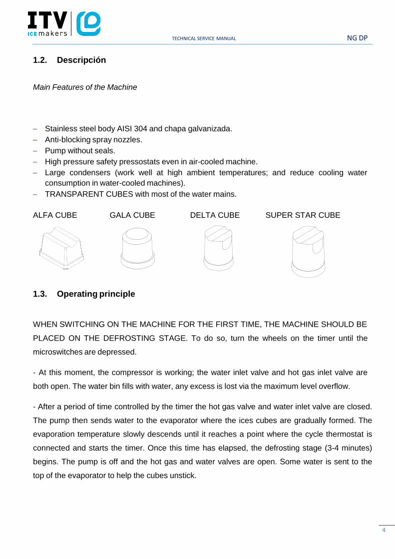
1.2. Descripción
Main Features of the Machine
Stainless steel body AISI 304 and chapa galvanizada.
Anti-blocking spray nozzles.
Pump without seals.
High pressure safety pressostats even in air-cooled machine.
Large condensers (work well at high ambient temperatures; and reduce cooling water
consumption in water-cooled machines).
TRANSPARENT CUBES with most of the water mains.
ALFA CUBE GALA CUBE DELTA CUBE SUPER STAR CUBE
1.3. Operating principle
WHEN SWITCHING ON THE MACHINE FOR THE FIRST TIME, THE MACHINE SHOULD BE
PLACED ON THE DEFROSTING STAGE. To do so, turn the wheels on the timer until the
microswitches are depressed.
- At this moment, the compressor is working; the water inlet valve and hot gas inlet valve are
both open. The water bin fills with water, any excess is lost via the maximum level overflow.
- After a period of time controlled by the timer the hot gas valve and water inlet valve are closed.
The pump then sends water to the evaporator where the ices cubes are gradually formed. The
evaporation temperature slowly descends until it reaches a point where the cycle thermostat is
connected and starts the timer. Once this time has elapsed, the defrosting stage (3-4 minutes)
begins. The pump is off and the hot gas and water valves are open. Some water is sent to the
top of the evaporator to help the cubes unstick.

NG DP TECHNICAL SERVICE MANUAL
5
4
- Once the defrosting stage is over, the cycle begins again, and so it continues until the bin is
full of ice, and contact between the bin thermostat situated at the top of the bin and the ice will
stop the machine. The bin thermostat will never stop the machine in mid-cycle.
OPERATING PRINCIPLE FOLLOWING THE ELECTRIC DIAGRAM (TIMER ON DEFROST -
MICROSWITCHES DEPRESSED).
- The ITV model NG has two switches:
1st In the frontal side of the machine (with led). This turns the machine on or off when we press
it.
2nd The second switch is located in the electrical panel. This one stops the condensing unit, but
keeps the hydraulic part in operation and allows to do the cleaning of the machine (except in
NDP20 model).
- Current reaches the machine via the line connecting the blue (1) and brown (2) terminals. The
brown wire connects the compressor and timer motor. The blue wire connects bin thermostat T1
which closes the circuit with 2. A different blue wire goes to 2 on terminal G1 which at this
moment is connecting 1 and 4.
- A red wire connects bin thermostat T1 and micros G1 and G2 which close the circuit with 4
and provide current via G1 to the timer G.
- At this point the following are connected:
❖ COMPRESSOR (S)
❖ WATER INLET VALVE (P)
❖ HOT GAS VALVE (Q)
❖ TIMER MOTOR (G)
- Since the motor of the timer (G) is working, during 13 minutes the roler of micro of the second
water inlet coil (cleaning valve drive) is depressed until the pins release the micro, closing this
valve.
- After 2 to 4 minutes micros G1 and G2 will open and close circuits 1-2.
NG DP TECHNICAL SERVICE MANUAL
- Via terminal 2 on micro G2, current reaches the pump. Circuit 4 on micro G2 which provides
current to the hot gas valve (Q) and water inlet valve (P) will be interrupted. Since the thermostat
is between 1 and 3 the timer will receive no current. The compressor continues switched on.
- Air-cooled machines have a fan (R) which is controlled by the pressostat (F).
- In water-cooled models without pressostatic valve, pressostat (J) opens and closes the
condenser electrovalve (K).
- Evaporator temperature decreases until the cycle thermostat (T2) set point is reached, at this
temperature circuit 1-2 will be closed and timer motor (G) will switch on.
- Once the cycle is over, the pins on the timer wheels will force the micros to change circuits,
stopping the pump and opening the hot gas valve and water valve. The combined effect of hot
gas and water sprayed on the top of the evaporator will release the ice cubes and change the
position of the cycle thermostat (T2).
- The ice production and defrosting cycle will continue until the ice storage bin is full, at which
point cycle thermostat (T1) will disconnect the machine, but never during a cycle, but at the
beginning of the defrosting stage, since during the production cycle, current will reach the pump
via terminals 1-2 of micro G1.
- The machine will remain disconnected until the level of ice in the bin drops below the
thermostat because of ice consumption. At this point the bin thermostat T1 changes and the
machine will start a new production cycle automatically.

NG DP TECHNICAL SERVICE MANUAL
1.4. Wiring diagrams
7
NG DP TECHNICAL SERVICE MANUAL
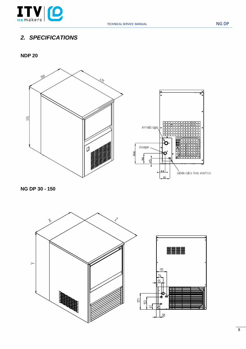
2. SPECIFICATIONS
NDP 20
NG DP 30 - 150
8
NG DP TECHNICAL SERVICE MANUAL
9
805
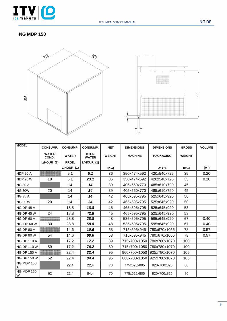
NG MDP 150
MODEL
CONSUMP.
WATER COND..
L/HOUR (1)
CONSUMP.
WATER
PROD.
L/HOUR (1)
CONSUMP.
TOTAL WATER
L/HOUR (1)
NET
WEIGHT
(KG)
DIMENSIONS
MACHINE
DIMENSIONS
PACKAGING
X*Y*Z
GROSS
WEIGHT
(KG)
VOLUME
(M3)
NDP 20 A 5.1 5.1 36 350x474x592 420x540x725 35 0.20
NDP 20 W 18 5.1 23.1 36 350x474x592 420x540x725 35 0.20
NG 30 A 14 14 39 405x560x770 485x610x790 45
NG 30W 20 14 34 39 405x560x770 485x610x790 45
NG 35 A 14 14 42 465x595x795 525x645x920 50
NG 35 W 20 14 34 42 465x595x795 525x645x920 50
NG DP 45 A 18.8 18.8 45 465x595x795 525x645x920 53
NG DP 45 W 24 18.8 42.8 45 465x595x795 525x645x920 53 NG DP 60 A 28.8 28.8 48 535x595x795 595x645x920 67 0.40
NG DP 60 W 30 28.8 58.8 48 535x595x795 595x645x920 67 0.40
NG DP 80 A 14.6 10.6 58 715x595x945 780x670x1055 78 0.57
NG DP 80 W 54 14.6 68.6 58 715x595x945 780x670x1055 78 0.57
NG DP 110 A 17.2 17.2 89 715x700x1050 780x780x1070 100
NG DP 110 W 59 17.2 76.2 89 715x700x1050 780x780x1070 100
NG DP 150 A 22.4 22.4 95 860x700x1050 925x780x1070 105
NG DP 150 W 62 22.4 84.4 95 860x700x1050 925x780x1070 105 NG MDP 150 A
22,4
22,4
70
775x625x805
820x700x825
80
NG MDP 150 W
62
22,4
84,4
70
775x625x805
820x700x825
80
NG DP TECHNICAL SERVICE MANUAL
10
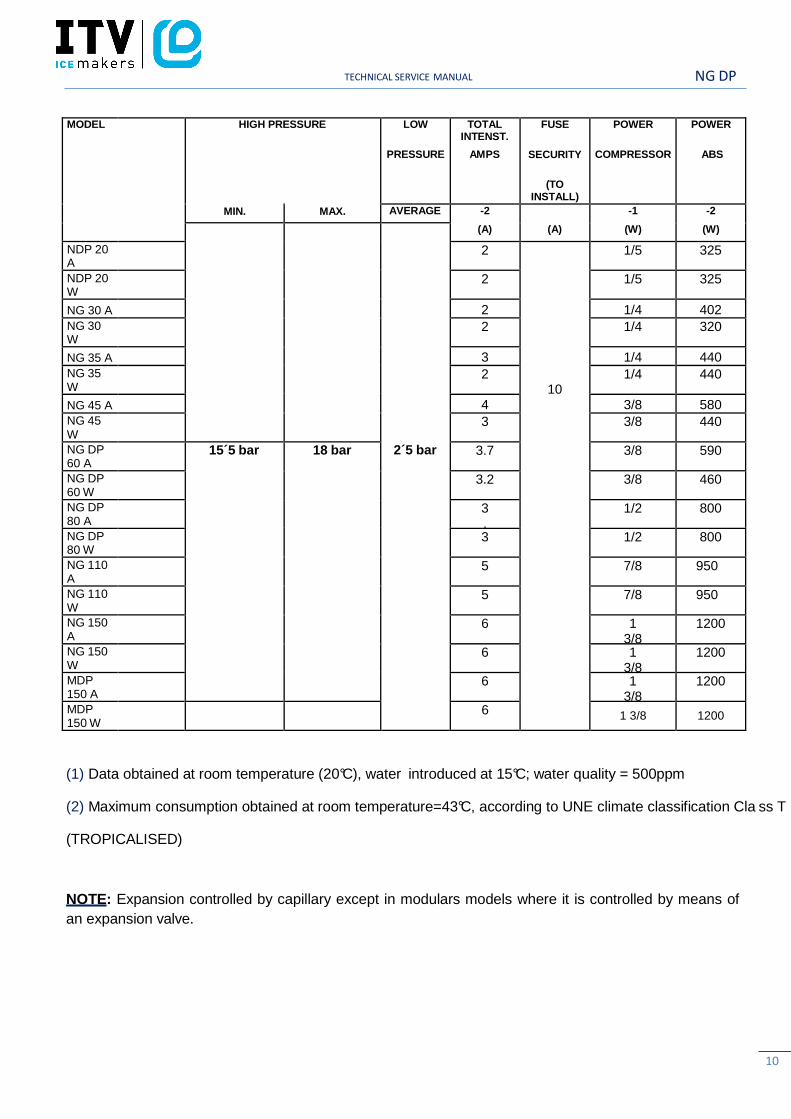
MODEL HIGH PRESSURE LOW
PRESSURE
TOTAL INTENST.
AMPS
FUSE
SECURITY
(TO INSTALL)
POWER
COMPRESSOR
POWER
ABS
MIN. MAX. AVERAGE -2
(A) (A)
-1
(W)
-2
(W)
2´5 bar
NDP 20 A
2
10
1/5 325
NDP 20 W
2 1/5 325
NG 30 A 2 1/4 402
NG 30 W
2 1/4 320
NG 35 A 3 1/4 440
NG 35 W
2 1/4 440
NG 45 A 4 3/8 580 NG 45 W
3 3/8 440
NG DP 60 A
15´5 bar 18 bar 3.7 3/8 590
NG DP 60 W
3.2 3/8 460
NG DP 80 A
3.6
1/2 800
NG DP 80 W
3 1/2 800
NG 110 A
5 7/8 950
NG 110 W
5 7/8 950
NG 150 A
6 1 3/8
1200
NG 150 W
6 1 3/8
1200
MDP 150 A
6 1 3/8
1200
MDP 150 W
6 1 3/8 1200
(1) Data obtained at room temperature (20°C), water introduced at 15°C; water quality = 500ppm
(2) Maximum consumption obtained at room temperature=43°C, according to UNE climate classification Cla ss T
(TROPICALISED)
NOTE: Expansion controlled by capillary except in modulars models where it is controlled by means of
an expansion valve.
NG DP TECHNICAL SERVICE MANUAL
11
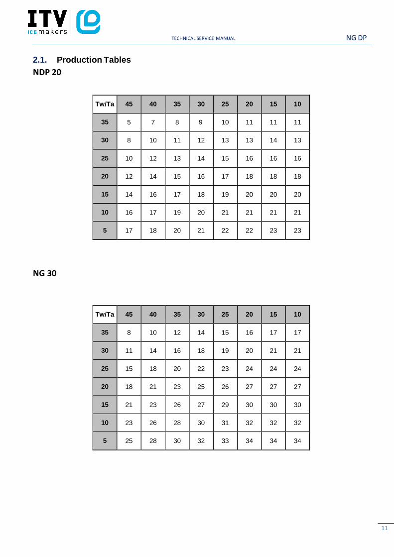
2.1. Production Tables
NDP 20
Tw/Ta
45
40
35
30
25
20
15
10
35
5
7
8
9
10
11
11
11
30
8
10
11
12
13
13
14
13
25
10
12
13
14
15
16
16
16
20
12
14
15
16
17
18
18
18
15
14
16
17
18
19
20
20
20
10
16
17
19
20
21
21
21
21
5
17
18
20
21
22
22
23
23
NG 30
Tw/Ta
45
40
35
30
25
20
15
10
35
8
10
12
14
15
16
17
17
30
11
14
16
18
19
20
21
21
25
15
18
20
22
23
24
24
24
20
18
21
23
25
26
27
27
27
15
21
23
26
27
29
30
30
30
10
23
26
28
30
31
32
32
32
5
25
28
30
32
33
34
34
34
NG DP TECHNICAL SERVICE MANUAL
12
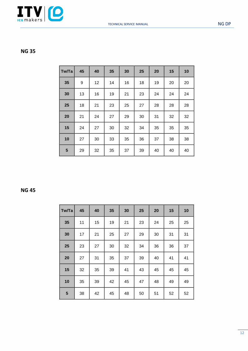
NG 35
Tw/Ta
45
40
35
30
25
20
15
10
35
9
12
14
16
18
19
20
20
30
13
16
19
21
23
24
24
24
25
18
21
23
25
27
28
28
28
20
21
24
27
29
30
31
32
32
15
24
27
30
32
34
35
35
35
10
27
30
33
35
36
37
38
38
5
29
32
35
37
39
40
40
40
NG 45
Tw/Ta
45
40
35
30
25
20
15
10
35
11
15
19
21
23
24
25
25
30
17
21
25
27
29
30
31
31
25
23
27
30
32
34
36
36
37
20
27
31
35
37
39
40
41
41
15
32
35
39
41
43
45
45
45
10
35
39
42
45
47
48
49
49
5
38
42
45
48
50
51
52
52
NG DP TECHNICAL SERVICE MANUAL
13
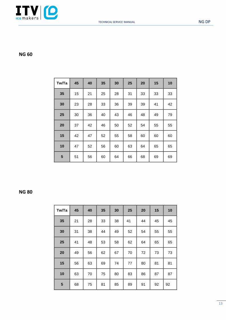
NG 60
Tw/Ta
45
40
35
30
25
20
15
10
35
15
21
25
28
31
33
33
33
30
23
28
33
36
39
39
41
42
25
30
36
40
43
46
48
49
79
20
37
42
46
50
52
54
55
55
15
42
47
52
55
58
60
60
60
10
47
52
56
60
63
64
65
65
5
51
56
60
64
66
68
69
69
NG 80
Tw/Ta
45
40
35
30
25
20
15
10
35
21
28
33
38
41
44
45
45
30
31
38
44
49
52
54
55
55
25
41
48
53
58
62
64
65
65
20
49
56
62
67
70
72
73
73
15
56
63
69
74
77
80
81
81
10
63
70
75
80
83
86
87
87
5
68
75
81
85
89
91
92
92
NG DP TECHNICAL SERVICE MANUAL
14
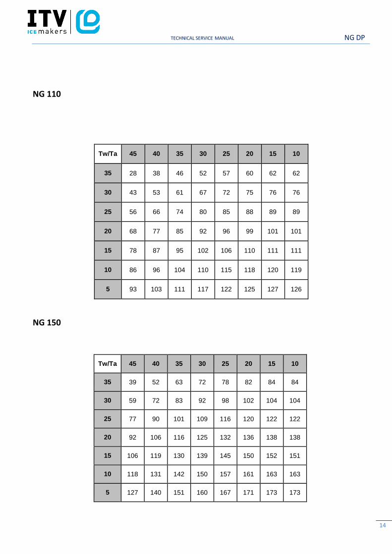
NG 110
Tw/Ta 45 40 35 30 25 20 15 10
35 28 38 46 52 57 60 62 62
30 43 53 61 67 72 75 76 76
25 56 66 74 80 85 88 89 89
20 68 77 85 92 96 99 101 101
15 78 87 95 102 106 110 111 111
10 86 96 104 110 115 118 120 119
5 93 103 111 117 122 125 127 126
NG 150
Tw/Ta 45 40 35 30 25 20 15 10
35 39 52 63 72 78 82 84 84
30 59 72 83 92 98 102 104 104
25 77 90 101 109 116 120 122 122
20 92 106 116 125 132 136 138 138
15 106 119 130 139 145 150 152 151
10 118 131 142 150 157 161 163 163
5 127 140 151 160 167 171 173 173
NG DP TECHNICAL SERVICE MANUAL
15
3. DELIVERY AND UNPACKING
Upon receipt, thoroughly inspect the packing container. If there appears to be damage to the
container contact the shipper immediately. Unpack unit in the presence of delivery personnel
noting any damage on the waybill.
ITV packing bears the “Green Point” on all models according to the European Directives on
management of Packaging and Waste Disposal.
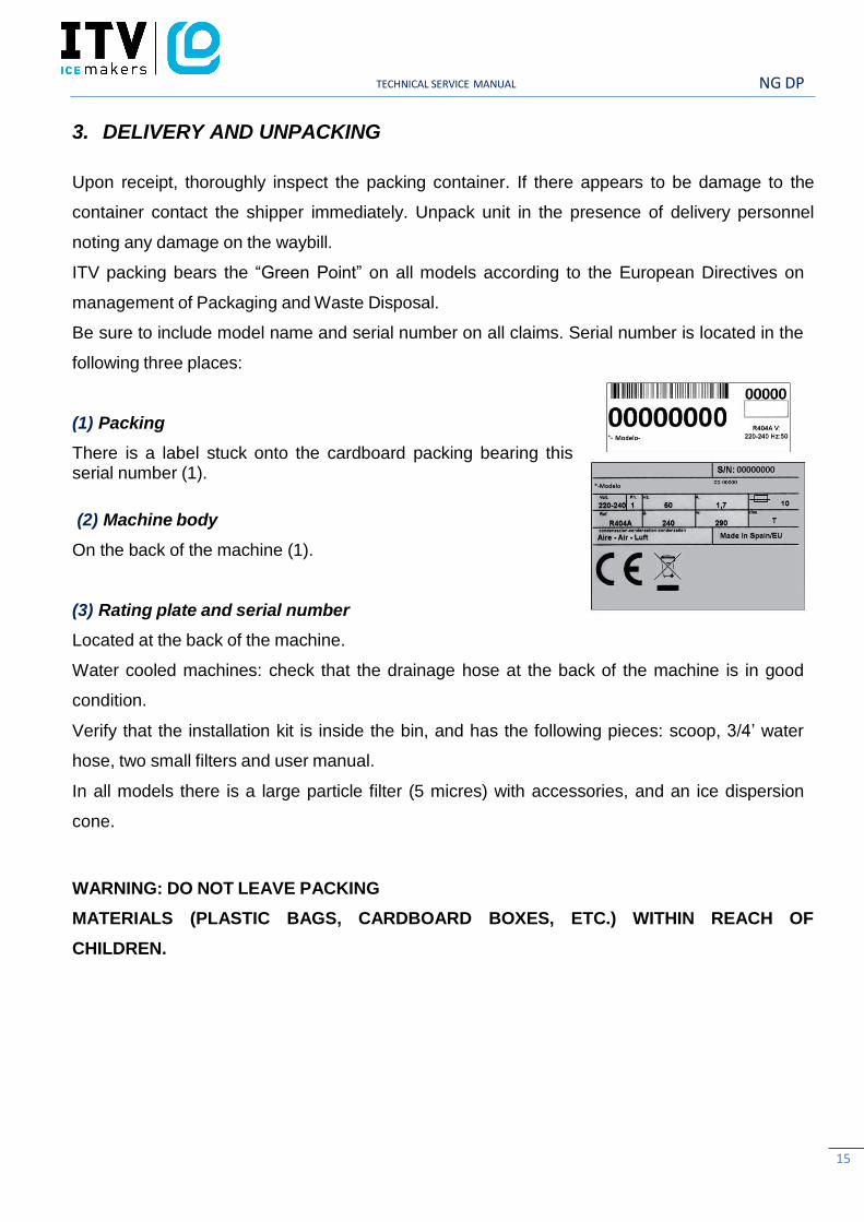
Be sure to include model name and serial number on all claims. Serial number is located in the
following three places:
(1) Packing
There is a label stuck onto the cardboard packing bearing this serial number (1).
(2) Machine body
On the back of the machine (1).
(3) Rating plate and serial number
Located at the back of the machine.
Water cooled machines: check that the drainage hose at the back of the machine is in good
condition.
Verify that the installation kit is inside the bin, and has the following pieces: scoop, 3/4’ water
hose, two small filters and user manual.
In all models there is a large particle filter (5 micres) with accessories, and an ice dispersion
cone.
WARNING: DO NOT LEAVE PACKING
MATERIALS (PLASTIC BAGS, CARDBOARD BOXES, ETC.) WITHIN REACH OF
CHILDREN.
NG DP TECHNICAL SERVICE MANUAL
16
4. INSTALLATION
4.1. Recommended Placement of Unit
IMPORTANT!
The NG machines are intended to work at room temperature between 5ºC and 43ºC and with
water temperature between 5ºC and 35ºC.
Difficulties during harvest cycle can appear below these minimum temperatures. Above the
maximum temperatures the life of the compressor becomes shorter and the production
decreases considerably.
IMPORTANT!
The new box-type frame in NG models allows a better ventilation in the air-cooled machines,
due to the fact that the condensers are placed in oblique position in the front part of the
machine.
The machines will work properly even if they are located in places with little ventilation at the
rear and lateral sides. The air is expelled by the front grill. Bear in mind the previous remarks if
the premises where the machine is located is very dusty or smoky
NG DP TECHNICAL SERVICE MANUAL
17
The floor on which the machine will be place should be solid and as leveled as possible.
4.2. Water and Drainage
Connecting Unit To Water Source
• Use 1.3 m. flexible tube (with the two filters attached) provided. NOTE: We advise using a
single faucet fixture.
• Water pressure should be between 0.7 and 6 Kgs/cm2. (10/85 Psi.)
• If water pressure exceeds these values, installation of appropriate corrective units will be
necessary.
• It is important that water tubing does not come close to or in contact with any heat sources or
heat generated by unit as this could decrease production.
Connecting Unit To Drain (Water -cooled Models)
• Drain must be located at least 150mm below machine level. Drain tube must have an inner
diameter of 30mm and a minimum gradient of 3 cm per metre.(3%).
4.3. Electrical connection
- The Unit is provided with a 1.5 m cord and schucko socket. If the cord is damaged shoud be
replaced by a cord or special assembly supplied by the manufacturer or after-sales service.
- It is strongly recommended to leave a minimum space between the rear side and the wall in
order to have an easy access to the plug without risks.
- It is advisable to install a switch and adequate fuses. Nominal voltage and intensity are
indicated on rating plate as well as on this manual's technical pages. Voltage fluctuations
greater than 10% can cause problems or prevent machine from starting.
- The Line to base of plug must have a minimum section of 2.5 mm2.
- Be sure voltage indicated on rating plate corresponds to that of mains supply.
IMPORTANT!
Supply socket must be properly earthed. Be sure to check standard for country where appliance
is going to be installed.
NG DP TECHNICAL SERVICE MANUAL
18
5. OPERATION
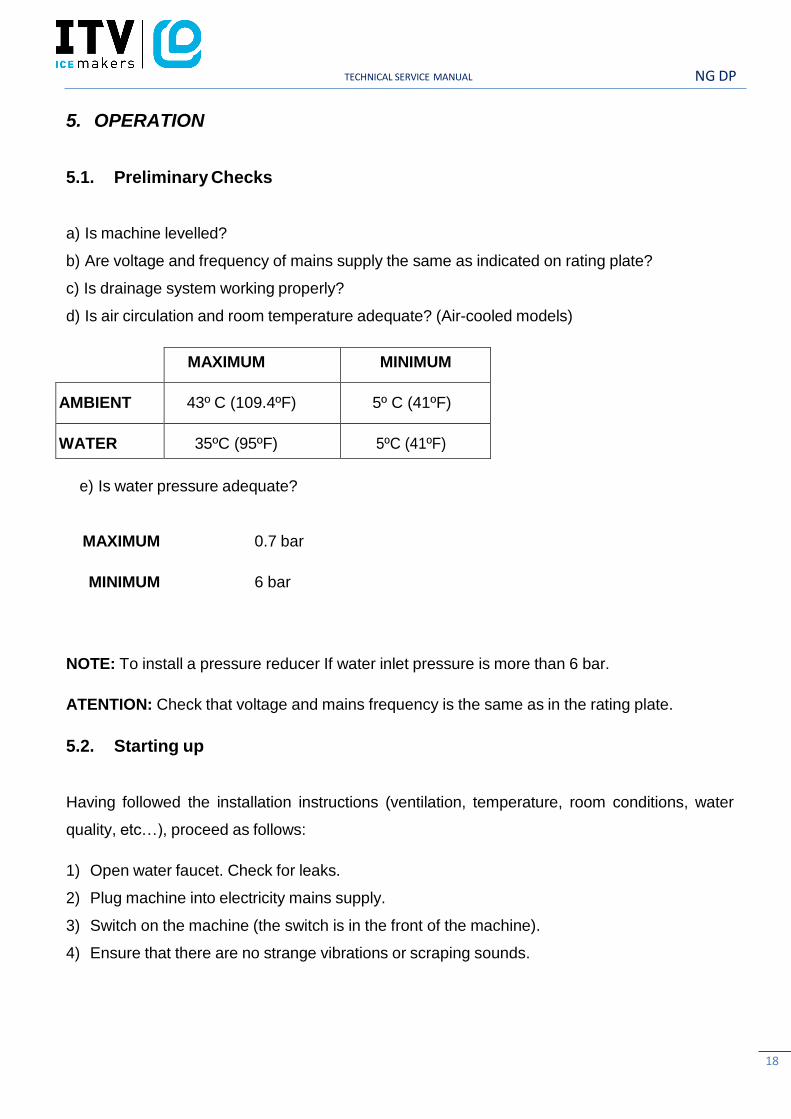
5.1. Preliminary Checks
a) Is machine levelled?
b) Are voltage and frequency of mains supply the same as indicated on rating plate?
c) Is drainage system working properly?
d) Is air circulation and room temperature adequate? (Air-cooled models)
MAXIMUM MINIMUM
AMBIENT
43º C (109.4ºF)
5º C (41ºF)
WATER
35ºC (95ºF)
5ºC (41ºF)
e) Is water pressure adequate?
MAXIMUM 0.7 bar
MINIMUM 6 bar
NOTE: To install a pressure reducer If water inlet pressure is more than 6 bar.
ATENTION: Check that voltage and mains frequency is the same as in the rating plate.
5.2. Starting up
Having followed the installation instructions (ventilation, temperature, room conditions, water
quality, etc…), proceed as follows:
1) Open water faucet. Check for leaks.
2) Plug machine into electricity mains supply.
3) Switch on the machine (the switch is in the front of the machine).
4) Ensure that there are no strange vibrations or scraping sounds.
NG DP TECHNICAL SERVICE MANUAL
19
5) Check that the water curtain moves freely.
6) Verify that the nozzles send water to the evaporator in the correct direction (uniform fans).
7) After 10 minutes, check that the water bin has no leaks on the maximum level overflow.
IMPORTANT!
ADVISE THE FINAL USER ON MAINTENANCE PROCEDURES WHICH ARE NOT INCLUDED IN WARRANTY, AS WELL AS THOSE BREAKDOWNS CAUSED BY NEGLECT OF PROPER MAINTENANCE PROCEDURES.
6. ADJUSTMENTS
6.1. Condenser water pressure valve
- This pressure switch controls high pressure by opening and closing the condenser water
valve. Differential is a fixed 1 Bar (14 psi.).
- The valve closes at 15 Bar (214 psi), which is equivalent to a condensation water exit
temperature of 38ºC (100ºF). . Below this pressure it will be difficult to unstick the cubes
during the defrosting cycle.
- Above this pressure, compressor life and ice production are both reduced.
Pressure can be increased by turning the small screw on the pressure switch clockwise. A full
turn is equivalent to about 1.5 Bar.
6.2. Fan pressure switch (air–cooled models)
Pressure Control operates on high pressure by starting and stopping fan. Differential is a fixed
(1 Bar or 14 psi.).
Cut-off pressure must be 15 Bar (214 psi). Low pressure values may cause difficulties during
harvest cycle. Higher pressure values may shorten compressor life and diminish ice production.
Pressure can be regulated by rotating screw on Pressure Control Valve (clockwise to increase
pressure). One full turn is equivalent to about 1.5 Bar.

NG DP TECHNICAL SERVICE MANUAL
20
Safety pressure switch
This safety device trips when discharge pressure is too
high. Pressure might exceed the limit when:
a) Air circulation is not sufficient, room temperature is
too high or condenser is dirty (air cooled models).
b) There is not enough water in the system or water
temperature too high in water cooled models.
HIGH PRESSURE REGULATION (fixed):
3030-22 Bar (from model 110 part # 2683) 27-21 Bar (380-296 psi.)
NG DP TECHNICAL SERVICE MANUAL
21
7. MAINTENANCE AND CLEANING INSTRUCTIONS
IMPORTANT!
**Maintenance and cleaning procedures as well as problems derived from failing to carry them
out are not covered by the warranty.
Proper maintenance is essential to obtain favorable ice quality and optimum functioning of unit.
Frequency depends on water quality and characteristics of room where unit is installed.
** Maintenance/cleaning procedures should take place at least once every six months. If
concentration of air pollutants is high, complete procedures on a monthly basis.
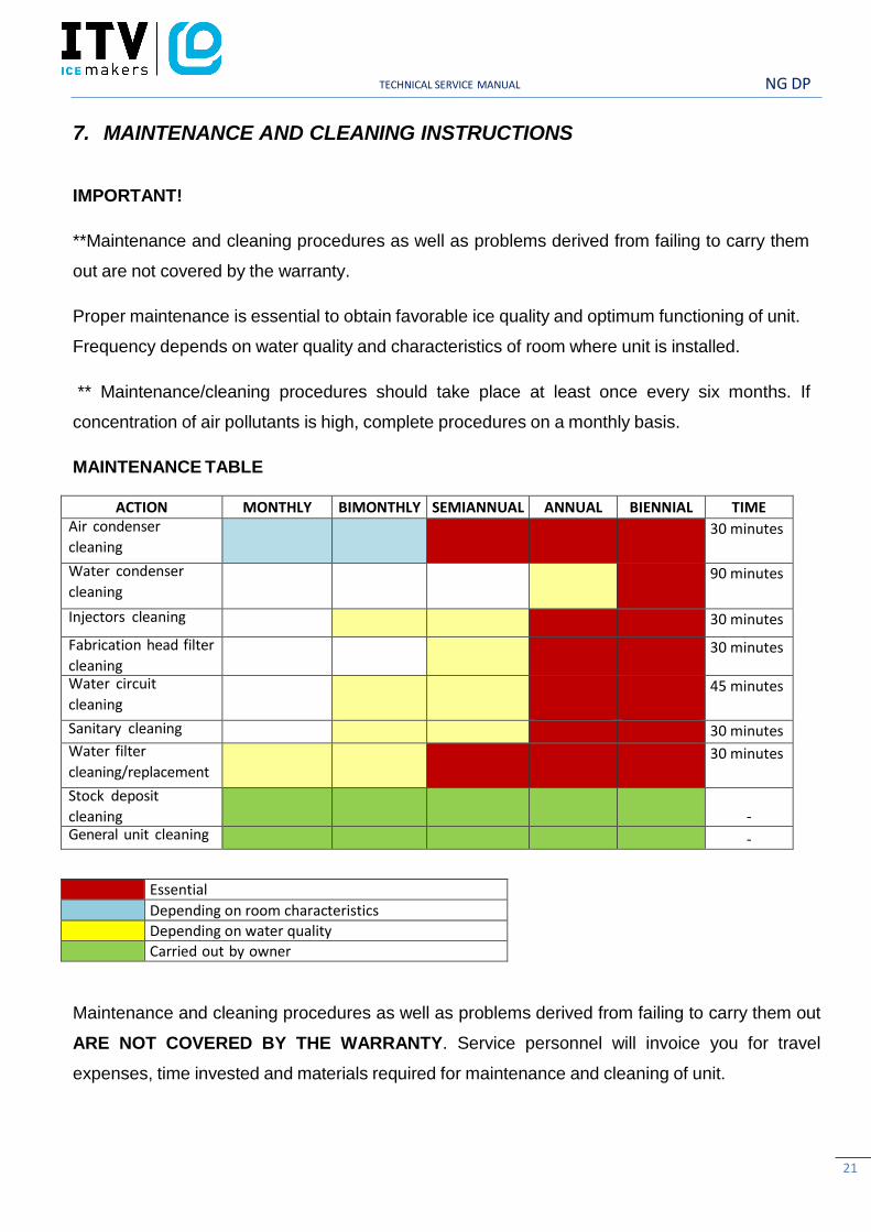
MAINTENANCE TABLE
ACTION MONTHLY BIMONTHLY SEMIANNUAL ANNUAL BIENNIAL TIME Air condenser
cleaning
30 minutes
Water condenser
cleaning
90 minutes
Injectors cleaning 30 minutes
Fabrication head filter
cleaning 30 minutes
Water circuit
cleaning
45 minutes
Sanitary cleaning 30 minutes Water filter
cleaning/replacement
30 minutes
Stock deposit
cleaning - General unit cleaning -
Essential
Depending on room characteristics
Depending on water quality
Carried out by owner
Maintenance and cleaning procedures as well as problems derived from failing to carry them out
ARE NOT COVERED BY THE WARRANTY. Service personnel will invoice you for travel
expenses, time invested and materials required for maintenance and cleaning of unit.
NG DP TECHNICAL SERVICE MANUAL
22
8. MAINTENANCE AND CLEANING PROCEDURES
WARNING: Unit should always be disconnected during maintenance/cleaning
procedures.
8.1. Water condenser
1) Disconnect machine.
2) Close water faucet.
3) Disconnect water entry/exit from condenser.
4) Prepare a solution of 50% phosphoric acid in distilled water.
5) Distribute solution through condenser. (Solution is more effective at 35°-40°C).
WARNING!
DO NOT USE HYDROCHLORIC ACID
8.2. Air condenser
1) Disconnect machine.
2) Close water faucet.
3) Clean condenser using a vacuum cleaner, soft brush and/or low-pressure air.
8.3. Evaporator / Water Through
1) Switch off the electric panel and place the timer in defrosting position.
2) Remove the top cover.
3) Place the overflow pipe. Remove the evaporator cover.
4) Prepare a solution of 50% phosphoric acid in distilled water. Do not use hydrochlorate acid.
Pour slowly this solution in the upper part of the evaporator, until it overflows in the
water tray. The mixture is more effective with the water between 35ºC. and 40ºC.
5) Let solution stand for 10 minutes.
6) Remove the overflow pipe and wait until the tray is empty. Put again the overflow pipe. (In
NG DP TECHNICAL SERVICE MANUAL
23
machines provided with discharge valve should be activated manually).
7) Refill the water tray to the maximum level with the same solution. Connect the machine
(close faucet) and wait 20 minutes.
8) Open faucet, put the timer forward up to the harvest cycle and once the ice has fallen
disconnect the machine and put the timer in defrosting position.
WARNING:** Discard ice produced during cleaning procedure.
NOW STARS THE SANITARY CLEANING
9) Connect the machine once it has finished entering water, remove the evaporator cover and
pour lye (one glass). Wait for 20 minutes.
10) Put the timer foward up to defrosting position. Once the ice has fallen, THROW AWAY THIS
ICE and let the machine produce another complete cycle.
IMPORTANT: ** Discard ice produced during this procedure.
11) Clean and assemble all the components. Verify that the grill is cleaned and that cubes slide
properly. Check that any strip gets blocked in the curtain. Check and/or change the water
inlet filters.
12) Check the adjustments of the cycle thermostat (cubes more or less filled) and that at the
end of the cycle the frost is closed to the compressor.
13) CHECK THAT THE NOZZLES ARE PROPERLY PLACED, THAT THE FORMED WATER
FANS ARE UNIFORM AND ALL EQUAL. If necessary, disassemble, clean and put again in
the right position.
8.4. Cleaning the ice bin
1) Unplug the machine, turn off water supply, and empty storage bin of ice.
2) Wipe with a kitchen cloth soaked in lye and detergent.
3) If white lime stains do not vanish, rub with some lemon or vinegar, wait for a few minutes
and wipe with the cloth again. Rinse with plenty of water, dry, and run the machine.
8.5. Cleaning the outside of the machine
Follow the same procedure as for the ice bin.

NG DP TECHNICAL SERVICE MANUAL
24
8.6. Spray nozzles and connecting pipes
1) Remove the curtain (it can be cleaned with vinegar or phosphoric acid, rinse, clean with lye,
rinse)
2) Remove the metal grill and clean likewise.
3) PULL UPWARDS THE CONNECTING PIPE. IT HAS BEEN ASSEMBLED BY PRESSING
IT INTO PLACE.
4) Disassemble the nozzles and the connecting tube covers and clean them.
5) Disassemble and clean the main filter of the production unit. (IT IS ASSEMBLED BY
PRESSING IT INTO PLACE)
6) Assemble the filter, nozzles and connecting tube.
ATTENTION: IT IS ESSENTIAL THAT SPRAY NOZZLES ARE COMPLETELY
PERPENDICULAR TO THE CONNECTING TUBES, OTHERWISE THE CUBES AT THE
ENDS MAY NOT RECEIVE WATER.
7) Place the grill over the nozzles, with the back slots secure.
8) Install the curtain, ensuring that all of the strips can move freely.
9) Run the machine but DISCARD THE FIRST SET OF ICE CUBES
8.7. Cleaning the water inlet filters
These round wire gasket filters placed on either end of the water hose to mains, often become
blocked in the first few days of use, Especially When The Plumbing Installation Is New. Clean
them under a jet of water.
8.8. Checking for water leaks
This must be done whenever maintenance is carried out on the machine: check all water
connections, braces, tubes and hoses in order to eliminate leaks and prevent breakages and
flooding.
NG DP TECHNICAL SERVICE MANUAL
25
9. SPECIAL ADVICE CONCERNING R-404A REFRIGERANT
R-404A is a mixture of 3 liquid-phase gases. On evaporating, the 3 component gases separate
Always use the liquid phase valve (at the end of condenser or accumulator) for refills and
purges.
When replacing a compressor, wash inside of circuit with a suitable solvent + pump, dry with
nitrogen gas, REPLACE THE DRIER WITH ONE SUITABLE FOR R-404A, which must
also have ANTI-ACID properties.
If you need to add oil, use one which is specific for R-404A (POE). If you are in doubt,
contact the machine manufacturer.
If there is a leak anywhere in the circuit where R-404A in the GAS phase, and a refill of
over 10% is required, then ALL THE GAS IN THE CIRCUIT MUST BE PURGED AND
THEN REFILL AS DESCRIBED PREVIOUSLY (LIQUID PHASE VALVE)
NG DP TECHNICAL SERVICE MANUAL
26
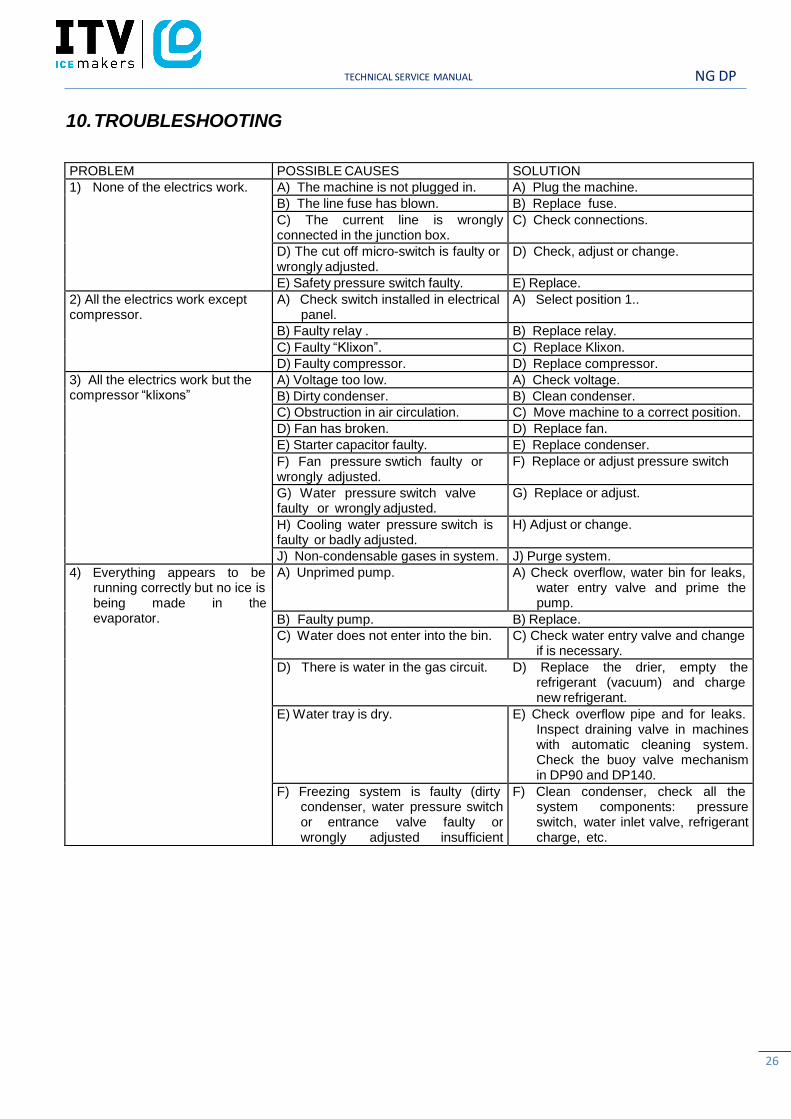
10. TROUBLESHOOTING
PROBLEM POSSIBLE CAUSES SOLUTION
1) None of the electrics work. A) The machine is not plugged in. A) Plug the machine.
B) The line fuse has blown. B) Replace fuse.
C) The current line is wrongly connected in the junction box.
C) Check connections.
D) The cut off micro-switch is faulty or wrongly adjusted.
D) Check, adjust or change.
E) Safety pressure switch faulty. E) Replace.
2) All the electrics work except compressor.
A) Check switch installed in electrical panel.
A) Select position 1..
B) Faulty relay . B) Replace relay.
C) Faulty “Klixon”. C) Replace Klixon.
D) Faulty compressor. D) Replace compressor.
3) All the electrics work but the compressor “klixons”
A) Voltage too low. A) Check voltage.
B) Dirty condenser. B) Clean condenser.
C) Obstruction in air circulation. C) Move machine to a correct position.
D) Fan has broken. D) Replace fan.
E) Starter capacitor faulty. E) Replace condenser.
F) Fan pressure swtich faulty or wrongly adjusted.
F) Replace or adjust pressure switch
G) Water pressure switch valve faulty or wrongly adjusted.
G) Replace or adjust.
H) Cooling water pressure switch is faulty or badly adjusted.
H) Adjust or change.
J) Non-condensable gases in system. J) Purge system.
4) Everything appears to be running correctly but no ice is being made in the evaporator.
A) Unprimed pump. A) Check overflow, water bin for leaks, water entry valve and prime the pump.
B) Faulty pump. B) Replace.
C) Water does not enter into the bin. C) Check water entry valve and change if is necessary.
D) There is water in the gas circuit. D) Replace the drier, empty the refrigerant (vacuum) and charge new refrigerant.
E) Water tray is dry. E) Check overflow pipe and for leaks. Inspect draining valve in machines with automatic cleaning system. Check the buoy valve mechanism in DP90 and DP140.
F) Freezing system is faulty (dirty condenser, water pressure switch or entrance valve faulty or wrongly adjusted insufficient refrigerant.
F) Clean condenser, check all the system components: pressure switch, water inlet valve, refrigerant charge, etc.
NG DP TECHNICAL SERVICE MANUAL
27
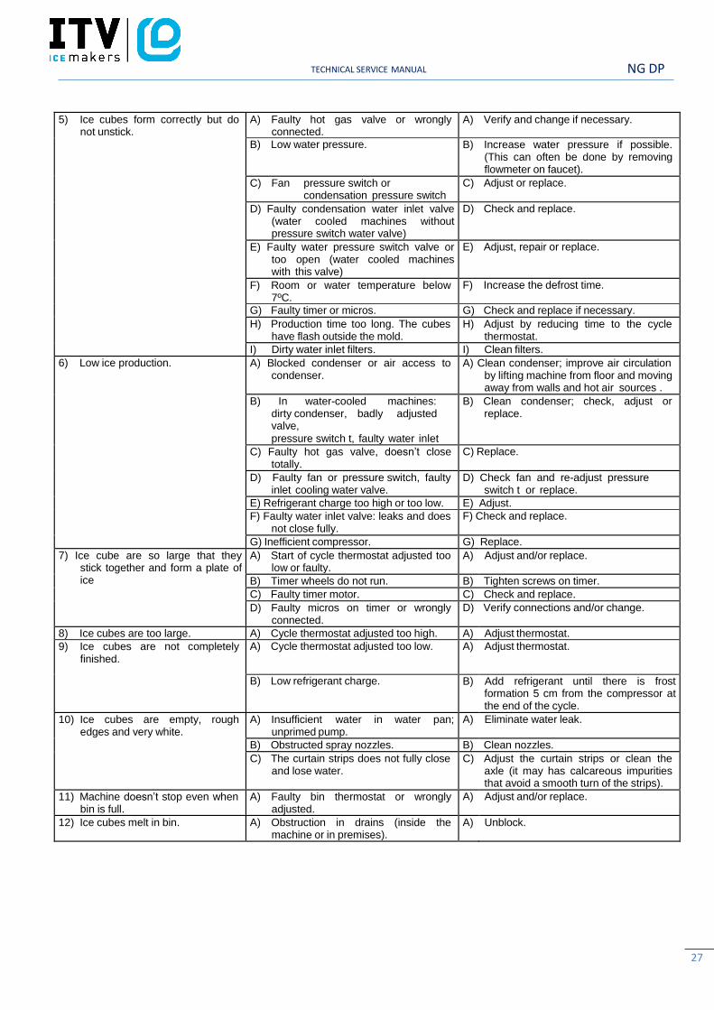
5) Ice cubes form correctly but donot unstick.
A) Faulty hot gas valve or wronglyconnected.
A) Verify and change if necessary.
B) Low water pressure. B) Increase water pressure if possible.(This can often be done by removingflowmeter on faucet).
C) Fan pressure switch orcondensation pressure switch
too low or faulty.
C) Adjust or replace.
D) Faulty condensation water inlet valve(water cooled machines withoutpressure switch water valve)
D) Check and replace.
E) Faulty water pressure switch valve ortoo open (water cooled machineswith this valve)
E) Adjust, repair or replace.
F) Room or water temperature below7ºC.
F) Increase the defrost time.
G) Faulty timer or micros. G) Check and replace if necessary.
H) Production time too long. The cubeshave flash outside the mold.
H) Adjust by reducing time to the cyclethermostat.
I) Dirty water inlet filters. I) Clean filters.
6) Low ice production. A) Blocked condenser or air access tocondenser.
A) Clean condenser; improve air circulationby lifting machine from floor and movingaway from walls and hot air sources .
B) In water-cooled machines: dirty condenser, badly adjusted valve,
pressure switch t, faulty water inlet valve or faulty pressostatic valve.
B) Clean condenser; check, adjust orreplace.
C) Faulty hot gas valve, doesn’t closetotally.
C) Replace.
D) Faulty fan or pressure switch, faultyinlet cooling water valve.
D) Check fan and re-adjust pressureswitch t or replace.
E) Refrigerant charge too high or too low. E) Adjust.
F) Faulty water inlet valve: leaks and doesnot close fully.
F) Check and replace.
G) Inefficient compressor. G) Replace.
7) Ice cube are so large that theystick together and form a plate ofice
A) Start of cycle thermostat adjusted toolow or faulty.
A) Adjust and/or replace.
B) Timer wheels do not run. B) Tighten screws on timer.
C) Faulty timer motor. C) Check and replace.
D) Faulty micros on timer or wronglyconnected.
D) Verify connections and/or change.
8) Ice cubes are too large. A) Cycle thermostat adjusted too high. A) Adjust thermostat.
9) Ice cubes are not completelyfinished.
A) Cycle thermostat adjusted too low. A) Adjust thermostat.
B) Low refrigerant charge. B) Add refrigerant until there is frostformation 5 cm from the compressor atthe end of the cycle.
10) Ice cubes are empty, roughedges and very white.
A) Insufficient water in water pan;unprimed pump.
A) Eliminate water leak.
B) Obstructed spray nozzles. B) Clean nozzles.
C) The curtain strips does not fully closeand lose water.
C) Adjust the curtain strips or clean theaxle (it may has calcareous impuritiesthat avoid a smooth turn of the strips).
11) Machine doesn’t stop even whenbin is full.
A) Faulty bin thermostat or wronglyadjusted.
A) Adjust and/or replace.
12) Ice cubes melt in bin. A) Obstruction in drains (inside themachine or in premises).
A) Unblock.