Embed Size (px)
Citation preview

Technical Report
NetApp Data Fabric with FlexPod and Cisco Intercloud Fabric Nabil Fares, Ganesh Kamath, NetApp
March 2015 | TR-4391
Abstract
This document describes the integration and architecture of NetApp® Private Storage, the
NetApp Cloud ONTAP™
operating system, and Cisco® Intercloud Fabric solutions. It includes
case studies, deployment procedures, and validations of these technologies.

2 NetApp Data Fabric with FlexPod and Cisco Intercloud Fabric TR-4391
TABLE OF CONTENTS
1 Introduction ........................................................................................................................................... 5
1.1 Intended Audience ..........................................................................................................................................5
1.2 Scope ..............................................................................................................................................................5
1.3 Assumptions and Prerequisites .......................................................................................................................6
1.4 Glossary of Terms ...........................................................................................................................................6
2 Background ........................................................................................................................................... 7
2.1 Business Challenges ......................................................................................................................................7
3 Introduction to NetApp Private Storage for AWS .............................................................................. 8
3.1 Overview .........................................................................................................................................................8
3.2 Technical Overview .........................................................................................................................................9
3.3 Solution Architecture ..................................................................................................................................... 10
3.4 References.................................................................................................................................................... 12
4 Introduction to NetApp Cloud ONTAP.............................................................................................. 12
4.1 Overview ....................................................................................................................................................... 12
4.2 Solution Architecture ..................................................................................................................................... 13
4.3 References.................................................................................................................................................... 13
5 Introduction to NetApp FlexPod ....................................................................................................... 13
5.1 Overview ....................................................................................................................................................... 13
5.2 References.................................................................................................................................................... 14
6 Introduction to Cisco Intercloud Fabric ........................................................................................... 15
6.1 Overview ....................................................................................................................................................... 15
6.2 Intercloud Fabric Components and Features ................................................................................................ 15
6.3 Intercloud Fabric Use Cases ......................................................................................................................... 16
6.4 References.................................................................................................................................................... 17
7 NetApp and Cisco ICF Solution Architecture .................................................................................. 17
7.1 Solution Architecture Components ................................................................................................................ 17
7.2 Integration ..................................................................................................................................................... 17
8 NetApp Private Storage for AWS ...................................................................................................... 25
8.1 Deployment Workflow and Assumptions ....................................................................................................... 25
8.2 NPS Network Architecture ............................................................................................................................ 25
8.3 Routing ......................................................................................................................................................... 27
8.4 Replication and Data Protection .................................................................................................................... 28

3 NetApp Data Fabric with FlexPod and Cisco Intercloud Fabric TR-4391
9 NPS and Cisco Intercloud Fabric Integration .................................................................................. 45
9.1 Solution Workflow Overview ......................................................................................................................... 45
9.2 ICF Deployment Overview ............................................................................................................................ 46
9.3 ICF Requirements and Prerequisites ............................................................................................................ 46
9.4 ICF Cloud VM Behavior ................................................................................................................................ 50
9.5 Cloud Services Router (CSR) ....................................................................................................................... 53
9.6 Integrating ICF with NPS Using CSR ............................................................................................................ 57
9.7 NPS and CSR Implementation ...................................................................................................................... 59
10 Cloud ONTAP and Intercloud Fabric Integration ............................................................................ 62
10.1 Guidelines and Limitations ............................................................................................................................ 62
10.2 Solution Architecture ..................................................................................................................................... 62
11 Testing and Validation ....................................................................................................................... 65
11.1 Create the Public VDC .................................................................................................................................. 65
11.2 Provision ICF VMs in the Public Cloud ......................................................................................................... 70
11.3 Access NPS Storage from the ICF Cloud VM Instance ................................................................................ 72
11.4 Use-Case Testing ......................................................................................................................................... 74
11.5 Cloud ONTAP and ICF ................................................................................................................................. 74
12 Conclusion .......................................................................................................................................... 75
Acknowledgements .................................................................................................................................. 76
LIST OF TABLES
Table 1) Cisco ICF glossary. ..........................................................................................................................................6
Table 2) AWS glossary. ..................................................................................................................................................6
Table 3) Industry glossary. .............................................................................................................................................7
Table 4) ICF main services. .......................................................................................................................................... 16
Table 5) On-premises FlexPod VLAN and IP assignments. ......................................................................................... 20
Table 6) Components. .................................................................................................................................................. 22
Table 7) NPS VLAN and IP assignments. .................................................................................................................... 26
Table 8) ICF component versions. ............................................................................................................................... 46
LIST OF FIGURES
Figure 1) Common cases for hybrid clouds. ...................................................................................................................8
Figure 2) NPS high-level architecture. .......................................................................................................................... 10
Figure 3) NetApp Private Storage for AWS. ................................................................................................................. 11
Figure 4) Cloud ONTAP high-level architecture. .......................................................................................................... 13
Figure 5) FlexPod component families. ........................................................................................................................ 14

4 NetApp Data Fabric with FlexPod and Cisco Intercloud Fabric TR-4391
Figure 6) Cisco Intercloud Fabric. ................................................................................................................................ 15
Figure 7) Cisco Intercloud Fabric services. .................................................................................................................. 16
Figure 8) NetApp and Cisco ICF architecture. .............................................................................................................. 18
Figure 9) NFS volume at the enterprise site. ................................................................................................................ 19
Figure 10) On-premises FlexPod network architecture. ............................................................................................... 20
Figure 11) ESX hosts with the mounted NFS volume. ................................................................................................. 22
Figure 12) VMware vDS configuration on the enterprise side. ..................................................................................... 23
Figure 13) vDS port provisioning. ................................................................................................................................. 24
Figure 14) VMware vDS security policy configuration for ICF. ..................................................................................... 24
Figure 15) NPS network architecture. .......................................................................................................................... 26
Figure 16) AWS routing table. ...................................................................................................................................... 27
Figure 17) NPS routing table. ....................................................................................................................................... 27
Figure 18) NPS and ICF high-level architecture. .......................................................................................................... 47
Figure 19) ICF VM interfaces. ...................................................................................................................................... 51
Figure 20) ICF VM interface mapping. ......................................................................................................................... 52
Figure 21) NPS and CSR architecture. ........................................................................................................................ 54
Figure 22) CSR-required VLANs. ................................................................................................................................. 55
Figure 23) CSR verification from PNSC. ...................................................................................................................... 56
Figure 24) CSR CLI. ..................................................................................................................................................... 56
Figure 25) CSR ARP table. .......................................................................................................................................... 57
Figure 26) Default routing behavior. ............................................................................................................................. 58
Figure 27) CSR default routing table. ........................................................................................................................... 59
Figure 28) Routing reference for NPS and ICF with CSR. ........................................................................................... 60
Figure 29) Routing verification between ICF and NPS. ................................................................................................ 62
Figure 30) Cloud ONTAP architecture. ......................................................................................................................... 63
Figure 31) Cloud ONTAP Cloud Manager. ................................................................................................................... 64
Figure 32) Cloud ONTAP network reachability from ICF VM. ....................................................................................... 65
Figure 33) Data access from AWS EC2 instances to NPS. .......................................................................................... 73
Figure 34) Data access from the ICF cloud VMs to NPS using the GRE tunnel. .......................................................... 74
Figure 35) Data access from ICF cloud VMs to Cloud ONTAP using NAT................................................................... 75

5 NetApp Data Fabric with FlexPod and Cisco Intercloud Fabric TR-4391
1 Introduction
This technical report provides an insight into NetApp Private Storage (NPS), Cloud ONTAP, and their
seamless integration with Cisco Intercloud Fabric (ICF). It provides a high-level summary of each
technology, technical implementation on the premises and in the cloud, and a detailed configuration and
validation of all the technologies working together for an enterprise hybrid cloud strategy.
It is becoming more critical for enterprise IT to find the right solutions and tools to enable seamless
adoption between private cloud and on-premises and public cloud infrastructures while maintaining
control of applications and providing a high-level user experience.
The NetApp Data Fabric provides flexibility with complete ownership of data while providing the ability to
leverage multiple public clouds. NPS, Cloud ONTAP, NetApp SnapMirror® software, and Cisco Intercloud
Fabric provide the key technologies to securely leverage a hybrid cloud for workload migrations,
development/test, backup, and disaster recovery in a flexible approach without cloud provider lock-in.
Cisco Intercloud Fabric builds highly secure hybrid clouds and extends enterprise virtualized data centers
to the public cloud while maintaining network and security policies. ICF provides complete freedom to
place workloads across multiple public clouds based on business and cost needs. The mobility of ICF
removes any demarcation between private and public clouds.
The unique partnership between NetApp cloud offerings (the NetApp Data Fabric) and Cisco Intercloud
Fabric enables a successful shift to the hybrid cloud. Enterprise data, compute, and public cloud–based
resources integrate for scalability with operational intelligence while enabling the ability to control costs
and data ownership. ICF moves workloads to the public cloud and SnapMirror moves data from the
enterprise to NPS, eliminating any potential latency impacting critical and noncritical applications.
Both NPS and ICF provide the capabilities for data and workload mobility with bidirectional migration,
practically eliminating provider lock-in. The option to port data and applications is a critical part of
hypercloud strategy, just as is pricing and flexibility.
1.1 Intended Audience
This document is intended for:
Customers, partners, and service providers looking to implement and integrate NPS, Cloud ONTAP, and Cisco Intercloud Fabric as part of a hybrid cloud strategy
End users and managers interested in continuous-availability solutions in the cloud for dev/test, compute augmentation, and disaster recovery strategies
1.2 Scope
The purpose of this report is to provide:
A high-level technical review of NetApp cloud solutions and Cisco ICF
A detailed design and implementation guide and configuration best practices
A high-level overview of architectural use cases with expected behaviors
Demonstrated solutions for Cisco Intercloud Fabric integration with NPS (section 9) and Cloud ONTAP (section 10)
The scope of this document is limited to the following:
Validation is limited to AWS and Equinix. Visit each technology reference site links for each technology.
It does not replace any official manuals or documents from NetApp and Cisco on the products used in the solution or documents from any other hardware vendor referenced in this report.

6 NetApp Data Fabric with FlexPod and Cisco Intercloud Fabric TR-4391
It does not discuss any performance impact or analysis from an end-user perspective during a disaster.
It does not discuss high-availability deployment and redundancy verification for hardware, tunnel, or virtualized environments. The assumption is that the end user follows the best practices provided for each of the technologies presented here.
1.3 Assumptions and Prerequisites
This document assumes that the reader has basic knowledge of the following:
NPS architecture and deployment
Amazon Web Services, specifically VPC, Routing, and Direct Connect
Cisco technologies and products
NetApp storage systems and the NetApp Data ONTAP® operating system
VMware® virtualization technologies and products
General networking
NetApp highly recommends that users follow the best practices for each technology presented in this
report.
1.4 Glossary of Terms
Tables 1 through 3 define the terms used to describe the technical architecture of the solution.
Table 1) Cisco ICF glossary.
Terminology Description
ICFD Intercloud Fabric Director (the main appliance used to manage the ICF environment)
PNSC Prime Network Services Controller
VSM Virtual Switch Module
ICX Intercloud Extender
ICS Intercloud Switch
ICA Intercloud Fabric Agent
ICL Intercloud Link (TLS tunnel)
CSR Cloud Services Router
Table 2) AWS glossary.
Terminology Description
VPC A virtual private cloud (VPC) is an isolated private (RFC 1918) IP address range (10.0.0.0/8, 172.16.0.0/12, 192.168.0.0/16). A VPC can be connected to other VPCs, to the Internet, or to other networks through a Direct Connect network connection.
VGW A virtual private gateway (VGW) is a virtual router used to connect your VPC to other networks. The VGW is the AWS endpoint for the Direct Connect network connection.
Direct Connect Direct Connect is a service offered by Amazon and participating colocation providers to establish a high-speed connection to the customer-provided network equipment in the colocation data center.

7 NetApp Data Fabric with FlexPod and Cisco Intercloud Fabric TR-4391
Terminology Description
EC2 Amazon Elastic Compute Cloud (EC2) provides computing resources through VM operating systems (OSs) for the AWS cloud. The VMs can run either Microsoft
®
Windows® or Linux
® OSs.
AMI An Amazon Machine Image (AMI) is a VM image in Amazon EC2. EC2 VMs are deployed from AMIs. AMIs can be purchased from the AWS Marketplace, or customers can build their own.
AWS Region An AWS region is a pool of AWS cloud resources tied to a geographic site. Each AWS region consists of multiple Availability Zones.
Availability Zone Availability Zones are distinct locations within an AWS region that are engineered to be isolated from failures in other Availability Zones. They also provide inexpensive low-latency network connectivity to other Availability Zones in the same region.
Table 3) Industry glossary.
Terminology Description
BGP Border Gateway Protocol (BGP) is the layer 3 routing protocol that AWS Direct Connect uses to advertise routes between the VPC network and the customer network located in the Direct Connect data center. BGP configuration on the customer network switch is used to advertise routes from the customer network into the VPC network.
GRE This stands for Generic Routing Encapsulation.
NAT This stands for Network Address Translation.
2 Background
The integration of NPS, Cloud ONTAP, and ICF enables us to deliver some very compelling solutions for
customers deploying a hybrid cloud strategy. The integration of NetApp Data Fabric solutions with Cisco
Intercloud Fabric paves the way for a solid entry into the hybrid cloud quickly and with minimal operational
learning curves, shifting the focus from complex to simpler adoption.
2.1 Business Challenges
A hybrid cloud approach provides organizations with the best of private and public clouds. Organizations
need the combined benefits with the advantages of a public cloud. They have become acutely aware that
a hybrid cloud might prove to be the better choice.

8 NetApp Data Fabric with FlexPod and Cisco Intercloud Fabric TR-4391
Figure 1) Common cases for hybrid clouds.
We selected the most common enterprise needs for validation: workload augmentation, dev/test, and
backup and recovery.
High compute demands are seasonal in the enterprise. Enterprises can have a deployment model in which the hyperscaler VM instances are spun up immediately (or workload burst into the cloud) when the demand for computing capacity spikes during busy periods to meet peak demands. Enterprises only pay for extra compute when it is needed. The NetApp infrastructure in Equinix can provide instant access to the workloads by using cloning or mirroring technology.
Enterprises can also quickly test new applications and quickly perform development and testing on demand with this cloud model. NetApp technology can be used to provision instant clones of the enterprise workload and make them accessible to the dev/test VMs in the cloud.
Enterprises can also have cost-effective DR with NetApp SnapMirror technology.
3 Introduction to NetApp Private Storage for AWS
3.1 Overview
The NetApp Private Storage for AWS solution is a hybrid cloud architecture that allows enterprises to
build an agile cloud infrastructure that combines the scalability and flexibility of the AWS cloud with the
control and performance of NetApp storage.
NetApp storage is deployed at an Equinix colocation data center where the AWS Direct Connect service
is available. The storage is connected to AWS computing resources through the AWS Direct Connect
network service.
Typical use cases for the NetApp Private Storage for AWS solution include the following:
Oracle®, Microsoft SQL Server
®, and SAP
® primary workloads
Disaster recovery
Development and testing

9 NetApp Data Fabric with FlexPod and Cisco Intercloud Fabric TR-4391
Big data analytics
Data with compliance requirements
Data center migration and consolidation
The NetApp Private Storage for AWS solution deployed at an AWS Direct Connect data center can also
be connected to on-premises data centers through multiprotocol label switching (MPLS) or through a
point-to-point virtual private network (VPN). Customers can then use efficient NetApp SnapMirror and
SnapVault® storage replication to move data closer to AWS computing resources.
From a business perspective, the solution offers customers the ability to shift capital expenses to
operational expenses. Customers can dynamically allocate computing, application, or backup resources
instead of building out on-premises data centers and infrastructure.
3.2 Technical Overview
The NetApp Private Storage for AWS solution combines computing resources from AWS with NetApp
storage deployed at AWS Direct Connect data centers. Connectivity from the NetApp storage to the AWS
cloud is made possible by the AWS Direct Connect network service.
The AWS Direct Connect network service offers dedicated high-bandwidth, low-latency, secure network
connectivity to the AWS cloud. When provisioned through the AWS Direct Connect dashboard, 1Gb/sec
and 10Gb/sec network connections are available and are provisioned manually by cross connection in the
AWS Direct Connect data center.
Customers who deploy the NetApp Private Storage for AWS solution at Equinix colocation data centers
can also provision AWS Direct Connect network connections through the Equinix Cloud Exchange portal
in 200Mb/sec or 500Mb/sec bandwidth sizes. 1Gb/sec and 10Gb/sec Direct Connect connections are
provisioned manually by cross connection.
In the AWS Direct Connect data center, the customer provides network equipment (switch or router) and
NetApp storage systems. Virtual machines (VMs) in the AWS cloud connect to the NetApp storage
through IP-based storage protocols (iSCSI, CIFS, or NFS). Additional MPLS or point-to-point VPN
network resources can be used to provide connectivity between AWS regions as well as connectivity to
on-premises data centers.

10 NetApp Data Fabric with FlexPod and Cisco Intercloud Fabric TR-4391
Figure 2) NPS high-level architecture.
3.3 Solution Architecture
The solution architecture consists of the following components:
AWS EC2
AWS VPC
AWS Direct Connect
Equinix colocation data center (AWS Direct Connect data center)
Equinix Cloud Exchange
Border Gateway Protocol (BGP)
Customer-provided layer 3 network equipment
NetApp storage (FAS and NetApp FlexArray™
software)
Solution architecture diagrams
Figure 3 shows the architecture of the NetApp Private Storage for AWS solution.

11 NetApp Data Fabric with FlexPod and Cisco Intercloud Fabric TR-4391
Figure 3) NetApp Private Storage for AWS.

12 NetApp Data Fabric with FlexPod and Cisco Intercloud Fabric TR-4391
3.4 References
NetApp Private Storage for AWS Solution Architecture
NVA-0009: NetApp Private Storage for Public Cloud for AWS
4 Introduction to NetApp Cloud ONTAP
4.1 Overview
NetApp Cloud ONTAP for AWS is a software-only storage appliance that runs the NetApp clustered Data
ONTAP storage OS in the cloud. Cloud ONTAP manages general-purpose Amazon Elastic Block Storage
(GP2 EBS) with clustered Data ONTAP and provides enterprise-class features on top of EBS. This gives
the customer access to NFS, CIFS, and iSCSI protocol support as well as to a rich feature set that
enhances the management and efficiency of your storage. Customers also have access to industry-
leading technologies such as NetApp SnapMirror and NetApp SnapVault data replication that enable
seamless connectivity for hybrid cloud resources.
Cloud ONTAP is launched and managed using the NetApp OnCommand® Cloud Manager application.
Cloud Manager is a web front end that enables the deployment and management of AWS public cloud
resources associated with Cloud ONTAP. Cloud Manager provides a flexible, intuitive interface for
activities such as deploying Cloud ONTAP working environments, intelligent allocation of additional AWS
EBS storage, creation of NetApp flexible volumes, and so on.
Cloud Manager can be deployed several different ways, including:
Into your local data center from the NetApp Support Software downloads site
Into an existing EC2 instance running a supported version of Windows
From the AWS Marketplace from an AMI into an EC2 instance
Refer to the OnCommand Cloud Manager Installation and Setup Guide and the OnCommand Cloud
Manager User Guide for more information.
Amazon Web Services Virtual Private Cloud
Amazon Web Services allows customers to create logically isolated areas called VPCs within an EC2
environment. A VPC gives customers a secure container for the deployment and management of EC2
resources. When connected by an IPsec-based VPN, a VPC acts as an extension to a local data center,
with security controls handled at several access points. Cloud ONTAP must be deployed within an AWS
VPC and subnet. Deployments into AWS EC2 Classic are not supported.
Cloud ONTAP Benefits and Use Cases
Deploy new storage systems in minutes
Leverage elastic cloud compute
Multiprotocol in the cloud
Data mobility: move data into and out of the cloud
Disaster recovery
On-demand test/dev

13 NetApp Data Fabric with FlexPod and Cisco Intercloud Fabric TR-4391
4.2 Solution Architecture
Figure 4 depicts the Cloud ONTAP architecture in AWS. Note that Cloud Manager is necessary to
manage Cloud ONTAP in AWS. Optionally, Cloud Manager can also be used to manage NPS (hence the
dotted line).
Figure 4) Cloud ONTAP high-level architecture.
4.3 References
TR-4352: Networking Configurations for NetApp Cloud ONTAP for Amazon Web Services
5 Introduction to NetApp FlexPod
5.1 Overview
FlexPod is a best practice data center architecture with a validated, standardized configuration. It can be
optimized to fit a variety of mixed application workloads and use cases as the customer moves to
virtualization and private or public cloud environments. It is built on three components:
Cisco Unified Computing System™
(Cisco UCS®)
Cisco Nexus® switches
NetApp Fabric-Attached Storage (FAS) systems
These components are connected and configured according to both Cisco and NetApp best practices and
they provide the ideal platform for running a variety of enterprise workloads with confidence. The NetApp
FlexPod® platform can scale up for greater performance and capacity (by adding compute, network, or

14 NetApp Data Fabric with FlexPod and Cisco Intercloud Fabric TR-4391
storage resources individually as needed), or it can scale out for environments that need multiple
consistent deployments (by rolling out additional FlexPod stacks). FlexPod delivers a baseline
configuration and also has the flexibility to be sized and optimized to accommodate many different use
cases.
Typically, the more scalable and flexible a solution is, the more difficult it becomes to maintain a single
unified architecture capable of offering the same features and functionality across each implementation.
This is one of the key benefits of FlexPod. Each of the component families shown in Figure 5 (Cisco UCS,
Cisco Nexus, and NetApp FAS) offers platform and resource options to scale the infrastructure up or
down while supporting the same features and functionality that are required under the configuration and
connectivity best practices for FlexPod.
Figure 5) FlexPod component families.
The deployment uses standard recommendations from the FlexPod Validation Guides (see the links
below) to configure the infrastructure.
5.2 References FlexPod Datacenter DesignZone
FlexPod Datacenter Design and Deployment Guides

15 NetApp Data Fabric with FlexPod and Cisco Intercloud Fabric TR-4391
6 Introduction to Cisco Intercloud Fabric
6.1 Overview
Cisco Intercloud Fabric for Business gives you choices. You choose how much added capacity you need
and when you need it; you can choose one or a group of providers, and you choose the rules that govern
access and use of this extension of your data center. You also choose when you use your capacity so
you can easily provide for peak times.
Cisco Intercloud Fabric for Business also gives you a unified system based on a single data center fabric.
Applications don’t know where the on-premises system ends and the cloud system begins, but you will
have all the visibility you need to manage the application and the hybrid cloud infrastructure.
With Cisco® Intercloud Fabric for Business, you can extend your data center or private cloud to the public
cloud, allowing you to acquire the added capacity you need, with no demarcation between your internal
cloud and the external one. You can also integrate your private cloud with clouds run by more than one
service provider, with consistent network and security policies across private and public clouds, With
Cisco Intercloud Fabric for Business, you get the agility, capacity you need, as well as security and
control.
6.2 Intercloud Fabric Components and Features
Figure 6 shows the Cisco Intercloud Fabric architecture. Figure 7 illustrates its main services, and Table 4
describes the services.
Figure 6) Cisco Intercloud Fabric.

16 NetApp Data Fabric with FlexPod and Cisco Intercloud Fabric TR-4391
Figure 7) Cisco Intercloud Fabric services.
Table 4) ICF main services.
Component Name Description
Cisco Intercloud Fabric Secure Extender
Cisco Intercloud Fabric Secure Extender provides enterprise with secure extension to public clouds. It is integrated with links to several public cloud providers. Cisco offers Cisco Intercloud Fabric for Providers so that additional service providers can quickly integrate their environments with the Cisco solution to create a hybrid cloud offering.
Cisco Intercloud Fabric Director
Cisco Intercloud Fabric has an end-user and IT portal, Cisco Intercloud Fabric Director, for administration and management of the public cloud extension. This single console manages a company’s private and hybrid clouds, and it is used for managing cloud network services and cloud virtual machine lifecycles.
Cisco Intercloud Fabric provides open APIs, which allow integration of third-party management tools. Additional management systems can provide advanced application deployment, monitoring, and assurance, as well as enforcement of business policies and compliance for network and security policies.
Cisco Intercloud Fabric for Business consists of the Secure Extender and Director components. The
solution is supported by Cisco Virtual Security Gateway (VSG) and Cisco Cloud Services Router (CSR)
solutions.
6.3 Intercloud Fabric Use Cases
Capacity augmentation: During the year, you may need more capacity, for example, during peak shopping seasons, or more computing power to generate quarterly reports. You also may need more capacity when your contact center is handling a peak numbers of calls and needs more support from your data center, or when you’re opening a new facility that strains your existing data center. With Cisco Intercloud Fabric for Business, the capacity you add will be indistinguishable from what your own data center already provides. In this hybrid cloud, the public and private systems merge transparently, both in what your employees can do using it, and in your management of it.
Development and testing: Your encapsulated data center in a public cloud is an excellent place to test and develop new software. Development and testing don’t drain data center resources that your

17 NetApp Data Fabric with FlexPod and Cisco Intercloud Fabric TR-4391
company needs for day-to-day operations, and when you’re finished, it is easy to move the new software into your regular operations because the environment in which it was tested is the same as your existing production environment.
Disaster recovery: If a disaster occurs, having your applications and basic data center configuration available in a transparent extension of your on- premises data center will let you regenerate your policies and rules, recover much of your data, and continue to work even if your primary data center is down for some time.
6.4 References
Cisco Intercloud Fabric Main Page
7 NetApp and Cisco ICF Solution Architecture
This section describes the architecture for NetApp Private Storage, NetApp Cloud ONTAP, and Cisco
Intercloud Fabric solutions, integrations of these technologies, case studies, deployment procedures, and
validations.
7.1 Solution Architecture Components
The solution architecture includes the following components:
NetApp storage (FAS)
NetApp Cloud ONTAP
Equinix colocation data center (NPS)
Cisco Nexus 3048 and 5548
Cisco ICF (including ICFD, PNSC, VSM, and CSR)
AWS default VPC (required by ICF)
AWS EC2
AWS Direct Connect
AWS EBS (Cloud ONTAP only)
BGP
GRE
NAT
VMware ESXi™
VMware vCenter™
The architecture components listed previously are not needed in each phase; they are a consolidated list
for the completed integrated solution of NPS, Cloud ONTAP, and ICF. As each phase is built, the
minimum required components are referenced again for clarification.
7.2 Integration
This solution integrates three product offerings from NetApp and Cisco: NPS, Cloud ONTAP, and Cisco
Intercloud Fabric. Each product is depicted individually and finally as a single architecture. Figure 8
shows a high-level architectural diagram with the different components integrated together.
The VLANs that are shown are:
On-premises VLAN—10.251.161.0/24
NPS AWS VLAN—10.251.162.0/24
AWS default VPC VLAN—172.31.0.0/16

18 NetApp Data Fabric with FlexPod and Cisco Intercloud Fabric TR-4391
Figure 8) NetApp and Cisco ICF architecture.
Note: The deployment guides describe a base FlexPod installation and configuration process and do not detail the additional components necessary for deploying ICF. However, the additional components are deployed as part of the on-boarding process because they are standard components, such as VLANs, VMKernel, port-groups, SVMs, LIFs, and so on. The screenshots of the components as they pertain to the ICF deployment are shown in subsequent sections.
We have a storage virtual machine (SVM) at the enterprise site with an NFS volume for hosting all the
ICF infrastructure components: ICFD, PNSC, VSM, ICX, and so on.
Figure 9 shows the SVM with the NFS volume that is mounted on all the ESXi hosts.

19 NetApp Data Fabric with FlexPod and Cisco Intercloud Fabric TR-4391
Figure 9) NFS volume at the enterprise site.
Note: Some of the FlexPod on-premises components (Cisco UCS and Cisco Nexus) are not necessary to accomplish the case studies in this TR. NetApp storage, however, is needed as an overall hybrid cloud strategy for DR and data storage mobility because SnapMirror is imperative.
Assumptions
The on-premises FlexPod platform, as noted in Figure 10, has direct connectivity to our enterprise DMZ
infrastructure. Your environment’s connectivity might vary; however, as long as routing is operating
properly for ICF to reach AWS, the outcome will be the same. An additional assumption is that the
storage is properly configured for SnapMirror to reach NPS or Cloud ONTAP.
On-Premises FlexPod Network Architecture
Figure 10 shows the on-premises FlexPod network architecture diagram. Connectivity between the
FlexPod and the DMZ is layer 3, and static routing is used to exchange routes between the two
environments.

20 NetApp Data Fabric with FlexPod and Cisco Intercloud Fabric TR-4391
Figure 10) On-premises FlexPod network architecture.
VLAN Configuration
Table 5 shows the VLANs and corresponding IP addresses provisioned on the on-premises FlexPod
configuration. The number of VLANs needed in production varies depending on the environment. The on-
premises VLAN is 10.251.161.0/24 and subnets of the VLAN were created to further aid in traffic
segregation.
Table 5) On-premises FlexPod VLAN and IP assignments.
VLAN/Interfaces IP Address VLAN Name
10 10.251.161.0/27 D09-MGMT-10.251.161.0/27

21 NetApp Data Fabric with FlexPod and Cisco Intercloud Fabric TR-4391
VLAN/Interfaces IP Address VLAN Name
20 10.251.161.32/27 D09-TUNL-10.251.161.32/27
1000 10.251.161.64/27 D09-NFS-10.251.161.64/27
1002 10.251.161.128/27 D09-INTG-10.251.161.128/27
103 10.251.240.40/29 DMZ-P2P-10.251.240.40/29
VLANs in Table 1 are used as follows:
VLAN10. This is the “management” VLAN and is used in the enterprise site for all in-band host management, including ESX
® hosts, vCenter, ICFD, PNSC, and VSM. This management VLAN can
also be used as the ICF link tunnel VLAN (ICL), but it is recommended to separate the management traffic from the tunnel traffic.
VLAN20. This is the tunnel VLAN that is dedicated for the ICF link tunnel provisioning. Although not mandatory, it’s recommended to separate the management and ICL traffic.
VLAN1000. This VLAN is specifically used for NFS storage traffic at the enterprise site, and is configured on the storage and server trunk interfaces.
VLAN1002. This VLAN is configured on the servers for user-facing traffic. We refer to it as Integration (Intg) but this is typically referred to as app VLAN or the workload VLAN. This VLAN is the primary VLAN used to extend to the AWS part of the ICF validation.
VLAN103. This is the Point2Point VLAN for layer 3 connectivity to our enterprise DMZ. There are no restrictions on using options such as switch virtual interface (SVI), P2P interfaces, or subinterfaces.
IP Addresses
There are no specific requirements for subnet sizes for ICF deployment. It is recommended that the in-
band management subnet have sufficient of IPs to accommodate your environment and ICF virtual
appliances. Depending on your deployment, plan at least five IP addresses for ICF without HA
deployment.
If you choose the option to use a separate VLAN for ICF tunnel, additional IP addresses are needed. ICF
tunnels require a pair of IP addresses per tunnel, so plan accordingly.
Routing
The Cisco Nexus 5548 switches handle all VLAN layer 3 interfaces and routing. The switches are
licensed with enterprise features.
To aid simplicity, we opted to use static routing with the DMZ. We advertise the enterprise VLAN—
10.251.161.0/24—and receive the default route from the DMZ. BGP and other routing protocols are
possible depending on the environment.
Physical Servers
Three physical top-of-rack (ToR) servers are used for our validation. For FlexPod Datacenter your options
are UCS C-Series (ToR) or Chassis; we opted to use ToR because of availability, not for technical
reasons. Any Cisco UCS servers in a FlexPod configuration can be used for deploying the infrastructure.
VMware ESX
ICF requires minimum ESX and vCenter versions for successful deployment. Reviews of Cisco’s
supported versions for ICF deployment and details of the latest ICF release notes and deployment guides
are available on the Cisco ICF website. Table 5 shows the versions that were used for this validation.

22 NetApp Data Fabric with FlexPod and Cisco Intercloud Fabric TR-4391
Table 6) Components.
Component Version
ESXi 5.1 with VMware
vCenter vCenter appliance 5.1 update 2a
Data ONTAP Data ONTAP 8.3
Note: If the environment runs different versions, then verify the interoperability of the different components using the NetApp Interoperability Matrix (IMT). Also verify the minimum requirements for ICF.
Note: Deploy the ESXi hosts according to the FlexPod data center design and deployment guides. Also follow the best practices that are documented in TR-4068: VMware vSphere on NetApp Clustered Data ONTAP Best Practices.
Figure 11 shows the ESXi hosts used for deploying the ICF infrastructure. All servers are identical in
configuration and have the NFS volume mounted on them. Multiple servers are used to demonstrate the
distributed nature of ICF as long as the VLANs are extended to all hosts.
Figure 11) ESX hosts with the mounted NFS volume.
VMware Networking Configuration
This validation uses a VMware vSphere® Distributed Switch (vDS) deployment for the configuration on the
enterprise side. All the ESXi hosts are part of the enterprise vDS, and all the VLAN port-groups are
defined on the vDS.
Figure 12 shows the VMware vDS port-group configuration on the enterprise side. View the different port-
groups with the appropriate VLANs defined for each of them.

23 NetApp Data Fabric with FlexPod and Cisco Intercloud Fabric TR-4391
Figure 12) VMware vDS configuration on the enterprise side.
Figure 13 shows a view of the port-group configuration on a specific ESXi host.

24 NetApp Data Fabric with FlexPod and Cisco Intercloud Fabric TR-4391
Figure 13) vDS port provisioning.
Note: In the security policies screen for the trunk port-group on the VMware virtual switch, set Promiscuous Mode, MAC Address Changes, and Forged Transmits to Accept in the VMware vSphere GUI. This requirement is applicable only if you use a VMware virtual switch and a distributed switch; it does not apply if you use a Cisco Nexus 1000V switch. The ICF installation will not succeed if the parameters are not set to “Accept.” Make sure that these changes do not affect your enterprise security policies.
Figure 14) VMware vDS security policy configuration for ICF.

25 NetApp Data Fabric with FlexPod and Cisco Intercloud Fabric TR-4391
8 NetApp Private Storage for AWS
Typically, there is no requirement for servers (compute) in the NPS architecture at the colocation facility.
As such, our deployment has all the necessary components to build the NPS to leverage AWS compute
and create the necessary VPN tunnels back to the enterprise. The configuration of the NetApp arrays at
the colocated site is similar to that of the enterprise, and it follows the guidelines for installing and
configuring FlexPod Express that are detailed in the TR.
This section describes the NPS deployment relevant to the overall solution integration. For an in-depth
NPS deployment workflow and step-by-step guide, refer to TR-4133: NetApp Private Storage for AWS
Solution Architecture and Deployment Guide.
8.1 Deployment Workflow and Assumptions
The workflow for deploying NPS for AWS includes the following tasks and assumptions:
1. An AWS account with the access key credentials.
2. Default VPC (this is a Cisco ICF requirement; NPS is compatible with all VPC types). If the default VPC is deleted, AWS Support can recreate it.
3. A Direct Connect service. This can be either 1G or 10G or single or dual connections for redundancy and HA.
4. BGP routing for Direct Connect. This is the only protocol supported by AWS.
5. Internet connectivity for VPN tunnel back to the enterprise. This tunnel is used for SnapMirror and NPS management. P2P and other WAN connectivity to the enterprise are also an option, but typically higher costs are associated with these options. Internet services are provided by any local provider to the colocation (Equinix) site or from Equinix as an OOB management service.
6. Hardware to support VPN tunnel back to the enterprise. We used an ASA5510, but any other device with VPN support suffices.
7. VPN tunnel to NPS permitting necessary subnets and TCP ports for SnapMirror. In addition to SnapMirror we also permit ICMP and SSH for troubleshooting purposes. SnapMirror ports are TCP 11104 and 11105.
8.2 NPS Network Architecture
Figure 15 shows the NPS diagram with FlexPod Express and Cisco ASA5510 for VPN connectivity back
to the enterprise. It also shows connectivity to AWS through Direct Connect and Virtual VGW to the
default VPC.

26 NetApp Data Fabric with FlexPod and Cisco Intercloud Fabric TR-4391
Figure 15) NPS network architecture.
VLAN Configuration
Table 7 shows the VLANs and corresponding IP addresses provisioned at the Direct Connect data
center. The NPS-assigned subnet block is 10.251.162.0/24; the block is broken into smaller subnets for
other network services. Other IP addresses are used for P2P links for NPS and AWS connectivity.
Table 7) NPS VLAN and IP assignments.
VLAN/Interfaces IP Address Description
10 10.251.162.160/27 SV5-MGMT-10.251.162.160/27
1000 10.251.162.64/27 SV5-NFS-10.251.162.64/27
Eth2.1.100 169.254.253.16/30 AWS-P2P-169.254.253.16
Eth1/1 192.168.254.252/30 FW1-P2P-192.168.254.252/30

27 NetApp Data Fabric with FlexPod and Cisco Intercloud Fabric TR-4391
IP Addresses
NPS and ICF don’t require any specific IP addressing scheme; the only requirement is that NPS-assigned
addresses must be reachable from AWS through Direct Connect. Typically, addresses in AWS and NPS
use RFC 1918 ranges. We suggest that you plan your address assignments to avoid any overlap conflicts
with enterprise ranges.
8.3 Routing
Routing protocols are selected based on requirements and convenience. For this deployment, for
example, we used static routes between NPS and the enterprise. Routing between NPS and AWS
requires BGP; this requirement stems from AWS for any type of Direct Connect service.
As seen in Figure 16, we’re accepting 172.31.0.0./16 from AWS and advertising 10.251.162.0/24 from
NPS. The NPS subnet is broken into smaller chunks to accommodate multiple VLANs, as noted in Table
7.
We’re accepting /27 from the enterprise FlexPod DC and sending /27. These subnets are specific to
permit SnapMirror relationships between the two locations.
Figure 16) AWS routing table.
Figure 17) NPS routing table.

28 NetApp Data Fabric with FlexPod and Cisco Intercloud Fabric TR-4391
8.4 Replication and Data Protection
SnapMirror technology offers a fast and flexible enterprise solution for mirroring or replicating data over
local area networks (LANs) and wide area networks (WANs). SnapMirror is a key component in enterprise
data protection strategies.
Replication can be performed within the same cluster or remotely to another cluster. NetApp Data ONTAP
provides integrated data replication technologies for creating replica copies that can be for DR to off-load
tape backup processes from the primary, to distribute datasets to other locations, and to create read/write
clones for test and development environments.
Some of the SnapMirror use cases and benefits are:
Integrated data protection
SnapMirror for disaster recovery
NetApp FlexClone® volumes for disaster recovery testing and application test/development
Data distribution and remote data access
This integration effort showcases the benefits of SnapMirror for these use cases:
Peak workload in AWS
Dev/test environments in AWS
DR purposes
We can quickly instantiate VMs in the AWS EC2 and those VMs can mount storage that is mirrored from
the enterprise site to the colocated data center. This can be done in one of two ways:
Make the destination volume read-write by breaking the SnapMirror relationship.
Clone the SnapMirror destination volume. Use a labeled Snapshot® copy for clone creation instead of
using a parent Snapshot copy that is used for the SnapMirror relationship.
The steps that are involved for the AWS EC2 VMs to mount NPS for AWS SnapMirror destination storage
are:
1. Use SnapMirror to mirror data from enterprise to NPS in the colocated data center.
2. Instantiate AWS EC2 VMs (if there aren’t any running currently).
3. Break the SnapMirror relationship or create FlexClone volumes of the SnapMirror destination in NPS AWS.
4. Mount the mirrored/cloned destination NFS volumes in NPS on the AWS EC2 VMs created in step 1.
Assumptions
The infrastructure for performing the SnapMirror replication is in place. All the intercluster LIFs should be configured and every intercluster LIF on every node in a cluster must be able to connect to every intercluster LIF on every node in the peer cluster. That is, all the intercluster LIFs on all the cluster nodes in the enterprise site should be able to reach all the intercluster LIFs on all the cluster nodes in the colocated data center.
Another assumption is that a few AWS EC2 VMs are currently up and running.
Refer to the following documentation and guides for SnapMirror on clustered Data ONTAP:
TR-4015: SnapMirror Configuration and Best Practices Guide for Clustered Data ONTAP
Clustered Data ONTAP Data Protection Guide
SnapMirror Data from Enterprise to NPS
The high-level steps for creating a SnapMirror relationship are as follows:

29 NetApp Data Fabric with FlexPod and Cisco Intercloud Fabric TR-4391
1. Create cluster peers (between enterprise cluster and NPS cluster at the colocated data center).
After the nodes in both clusters are configured with intercluster LIFs, the clusters have to be peered together to allow the creation of replication relationships between the clusters. Cluster peering must be configured to allow any replication to occur between different clusters. Essentially, the cluster peer feature allows two clusters to coordinate and share resources between them.
2. Create an SVM peer (between the SVMs at the enterprise cluster and the NPS cluster at the colocated data center).
SVM peering is the act of connecting two SVMs to allow replication to occur between them. Before creating any SnapMirror relationships between a pair of SVMs, you must have an SVM peer relationship between the pair of SVMs. SVM peering is a permission-based mechanism and is a one-time operation that must be performed by the cluster administrators.
3. Create a SnapMirror relationship.
After the cluster peer relationship and SVM peer relationship have been successfully created between the two clusters, create the intercluster SnapMirror relationships. Replication between volumes in two different SVMs in different clusters operating in clustered Data ONTAP is primarily used for providing DR to another site or location.
Cluster Peering
NetApp OnCommand System Manager can be used for creating and managing SnapMirror relationships.
OnCommand System Manager includes a wizard used to create SnapMirror DP relationships, schedules
to assign to relationships, and the destination volume, all within the same wizard.
Note: The new relationship has to be created from the destination cluster, which is from the NPS in the colocated data center.
1. Start the OnCommand System Manager managing the NPS cluster at the colocated site. Because OnCommand System Manager is on box for clustered Data ONTAP 8.3, enter the cluster management IP in a browser to open the OnCommand System Manager.
2. Create an authenticated cluster-peer relationship from System Manager. Click the Cluster hierarchy in the left navigation pane. Click Peers and then Create.
3. Enter a passphrase and the intercluster LIF IPs of the nodes at the enterprise site (on-premises cluster) and click Create.

30 NetApp Data Fabric with FlexPod and Cisco Intercloud Fabric TR-4391
A pop-up message appears advising you to perform the same operation at the enterprise site.
4. The peer status appears as “unavailable” and “pending” until the same operation is repeated at the peer cluster site, which is the enterprise site.

31 NetApp Data Fabric with FlexPod and Cisco Intercloud Fabric TR-4391
5. Using OnCommand System Manager, repeat the same peer creation process at the enterprise site. Supply the matching passphrase and the intercluster LIF IPs of the nodes in the NPS cluster at the colocated site.
6. The same warning pop-up message appears again advising you to create the peer, the operation that was performed in step 4. Click OK.

32 NetApp Data Fabric with FlexPod and Cisco Intercloud Fabric TR-4391
7. View the cluster peer relationship details from OnCommand System Manager. Confirm that the cluster peer was configured successfully at both ends.
At the enterprise site:
At the colocated site:

33 NetApp Data Fabric with FlexPod and Cisco Intercloud Fabric TR-4391
SVM Peering
SVM peering is a two-step process:
1. Step 1: Create an SVM peer from the destination.
2. Step 2: Accept the SVM peer from the source.
Step 1
1. Create an SVM peer by issuing the following command from the SVM on the destination cluster, which is the NPS at the colocated data center:
vserver peer create –vserver <destination vserver name> -peer-vserver <source vserver> -
applications snapmirror –peer-cluster <source cluster>
2. Issue a “vserver peer show” command to view the status.
At the destination colocated site, the peering status appears as “initializing.”
At the source-enterprise site, the peering status appears as “pending.”

34 NetApp Data Fabric with FlexPod and Cisco Intercloud Fabric TR-4391
Step 2
1. Accept the SVM peer from the source. Issue the following command at the source SVM, which is the enterprise site.
vserver peer accept –vserver <source vserver> -peer-vserver <destination vserver>
2. Issue the vserver peer show command and confirm that the peering is successful.
Creating SnapMirror Relationships
The SnapMirror relationship has to be created at the destination. Bring up the System Manager managing
the NPS cluster at the colocated site.
1. Expand the Storage Virtual Machines hierarchy. Select the destination SVM and navigate to Protection > Create > Mirror.

35 NetApp Data Fabric with FlexPod and Cisco Intercloud Fabric TR-4391
2. The SnapMirror creation wizard appears. Select the relevant source cluster, the source SVM, and the source volume that needs to be mirrored.
By default, the destination volume name is in the <SourceSVM_SourceVolumeName_Mirror>
format. You can either select the destination volume on the destination SVM or create a destination volume on the destination SVM.

36 NetApp Data Fabric with FlexPod and Cisco Intercloud Fabric TR-4391
3. You can also select or create a SnapMirror policy and schedule. Select the “Initialize Relationship” checkbox to start the baseline transfer and click Create.

37 NetApp Data Fabric with FlexPod and Cisco Intercloud Fabric TR-4391
The summary of the SnapMirror relationship configuration and status appears as follows:

38 NetApp Data Fabric with FlexPod and Cisco Intercloud Fabric TR-4391
4. View the relationship status of the baseline data transfer either through the CLI or the GUI.
From the UI:

39 NetApp Data Fabric with FlexPod and Cisco Intercloud Fabric TR-4391
From the CLI:
Issue a “snapmirror show” command on the destination cluster to view the SnapMirror
relationship status and the transfer progress of the baseline mirror.
5. Verify that the baseline transfer completed successfully.

40 NetApp Data Fabric with FlexPod and Cisco Intercloud Fabric TR-4391
Create FlexClone Volume of the Destination SnapMirror Volume
1. Navigate to the Storage Virtual Machines hierarchy in the left pane. Select the destination SVM and navigate to Storage > Volumes.
2. Click the Clone option in the menu bar or right-click the SnapMirror destination volume. Select Clone > Create > Volume.

41 NetApp Data Fabric with FlexPod and Cisco Intercloud Fabric TR-4391
3. Enter a name for the FlexClone volume or retain the default name. Select the Thin Provisioning checkbox to allocate space as used. This might vary depending on the customer environment.
Also, choose the relevant FlexClone parent Snapshot copy on which the cloned volume will be based. This example has a labeled Snapshot copy that was created on the source for cloning purposes. Selecting a Snapshot copy that was created by the SnapMirror relationship will cause SnapMirror updates to fail.
4. A pop-up message appears that states that SnapMirror updates might fail if the clone is based on a Snapshot copy created by the SnapMirror relationship. Click Yes to create the cloned volume.
5. Verify that the volume was cloned successfully.

42 NetApp Data Fabric with FlexPod and Cisco Intercloud Fabric TR-4391
6. Mount the volume to a junction path. Navigate to Storage > Namespace, and click Mount.
7. Select the cloned volume and enter a junction name. This name will be used to mount the volume on the AWS EC2 VMs.

43 NetApp Data Fabric with FlexPod and Cisco Intercloud Fabric TR-4391
8. Verify that the volume is mounted successfully at the junction. Also note that the export policy for the NFS volume will be set to “default.” In this example we modified the default export policy rules to allow the EC2 VMs to mount the NFS volume.
Note: The same operation can also be repeated by breaking the SnapMirror relationship and creating a read-write flexible clone of the destination volume. After the relationship is broken, the volume needs to be junctioned, as shown in step 6.

44 NetApp Data Fabric with FlexPod and Cisco Intercloud Fabric TR-4391
Mount the Volume on AWS EC2 VMs
This example uses a UNIX®-based EC2 instance and mounts an NFS volume. You could also use a
Windows EC2 instance to access a CIFS or any other EC2 instance type to mount an iSCSI LUN from the
destination SVM based on the configuration. The EC2 instances can be present in any Availability Zones,
but they should be in the same region as NPS. You could also access a CIFS share or an iSCSI LUN
based on the SVM configuration at the destination.
1. Note the relevant data LIF IPs of the destination SVM. Navigate to the Cluster hierarchy pane and expand Configuration. Navigate to Network > Network Interfaces and note the relevant Data LIF IP that will be used to mount the FlexClone volume using NFS.

45 NetApp Data Fabric with FlexPod and Cisco Intercloud Fabric TR-4391
2. Log in to a UNIX-based AWS EC2 VM and mount the FlexClone volume.
mount –t nfs <Data LIF IP noted earlier>:/<junctioned_volume_name> <mountpoint>
Summary
We saw a practical demonstration of the use cases that were discussed in the earlier sections. NetApp
Data Fabric integration with Cisco Intercloud helps businesses be agile and realize benefits quickly.
9 NPS and Cisco Intercloud Fabric Integration
This section describes the deployment methodology of ICF on FlexPod Datacenter in the enterprise and
AWS and the integration with NPS. The integration of ICF and Cloud ONTAP is also described in
subsequent sections.
The steps in this section do not focus on a step-by-step installation process of ICF; instead, they focus on
requirements for, recommendations for, and validation concerning how to leverage ICF with NPS and
Cloud ONTAP for an overall hybrid cloud strategy. Up-to-date and step-by-step ICF installation guides are
available from the Cisco website.
9.1 Solution Workflow Overview
The following is a summary of the solution workflow:

46 NetApp Data Fabric with FlexPod and Cisco Intercloud Fabric TR-4391
1. Create the enterprise VMs and mount NFS shares from the enterprise FlexPod platform.
2. Set up the SnapMirror relationships between the enterprise on-premises FlexPod and NPS in AWS.
3. Install and configure ICF and its components, including Intercloud Services (CSR and VSG).
4. Import templates into ICF from ESX and instantiate cloud VMs in AWS using ICF.
5. Build the necessary tunnels and NAT from ICF to NPS.
6. Break the SnapMirror relationship or clone the SnapMirror destination.
7. Mount NFS shares on destination ICF cloud VMs.
9.2 ICF Deployment Overview
To deploy ICF, complete the following steps:
1. Verify that the ESX deployment meets the minimum ICF version requirements listed in Table 8.
2. Verify that enterprise firewalls permit all required outbound ports.
3. Create an AWS account in the default VPC with restricted access credentials.
4. Install Intercloud Fabric Director and its components using the OVA in the infrastructure bundle.
5. Apply the necessary ICF licenses.
6. Create the Intercloud Fabric Cloud and enable the necessary services (CSR, VSG, and so on).
7. Configure the Cloud Services Router.
8. Create the public virtual data centers (VDCs) from the ICF GUI and create the desired VM templates.
9. Migrate VMs from the enterprise to the cloud or instantiate VMs in AWS using the templates that were created in previous steps.
10. Access NPS storage from the AWS EC2 instances.
9.3 ICF Requirements and Prerequisites
Intercloud Fabric has several networking and infrastructure requirements. However, security requirements
are most critical for a successful and streamlined deployment.
The integration assumes successful deployments of VMware ESXi and vCenter with the required
versions listed in Table 8, NPS readiness at the colocation, and proper enterprise firewall rules allowing
ICF communication with AWS.
Note: Our ICF deployment was simplified by working closely with our enterprise security team. This was very critical since the deployment was connected to our production network as in any customer environment. We chose this approach to understand all required phases based on production deployment and not a closed-lab setup.
Table 8) ICF component versions.
Component Version
ESXi 5.1 with VMware vDS
(Cisco Nexus 1000v was not used in the validation testing)
vCenter vCenter appliance 5.1 update 2a
ICF 2.1.2 (this is an infrastructure bundle that contains PNSC, VSM, ICX, and ICS images)

47 NetApp Data Fabric with FlexPod and Cisco Intercloud Fabric TR-4391
Architecture
Figure 18) NPS and ICF high-level architecture.
Networking
Intercloud Fabric requires several networking requirements for connectivity. At a minimum, you will
require:
A common “management” VLAN. This VLAN will be used for management of all ICF components (PNSC, ICX, cVSM, and so on). IPs in this VLAN will be needed for all Intercloud components. This is VLAN10 in our on-premises FlexPod configuration.
A VLAN for the site-to-site tunnel. This is optional because the management interfaces of ICX/ICS can be used as the endpoints of the tunnel. The endpoint IP addresses obviously need to be able to communicate with the public cloud provider across the ports outlined. In this validation effort, we have taken the view that we want management traffic contained internally and not mixed with external traffic, and that it should be completely isolated for performance and security reasons. Therefore, we separated the management and the tunnel VLANs, and IPs from this VLAN20 will be assigned to the tunnel interfaces of ICX/ICS. Those IPs will comprise the endpoints of the site-to-site tunnel. In this implementation the ICX tunnel interface IP will be the “source” address in creating firewall rules and our NAT rules on the enterprise firewall.
More than one workload VLAN. These workload VLANs will be trunked from the enterprise to the public cloud across the site-to-site tunnel. This validation effort has a single workload VLAN (VLAN1002) that is extended to the public cloud. You can also trunk workload VLANs that are deployed according to the standard three-tier stack model comprised of a “web” tier, an “app” tier, and a “db” tier, with each tier a unique VLAN. Then these three VLANs will be trunked from the enterprise to the public cloud across the site-to-site tunnel.
Cloud Provider and Firewall Ports
Create an AWS account if you don’t already have one.
Create an AWS access key with restricted access.

48 NetApp Data Fabric with FlexPod and Cisco Intercloud Fabric TR-4391
A default VPC is required for ICF. Make sure that your AWS supports this option and that the VPC is not deleted.
If you select to have your firewall rules created with destination IP addresses for granular security controls, Amazon’s IP address blocks are available at Amazon EC2 Public IP Ranges.
ICF requires that the following ports be opened on the enterprise firewalls to communicate successfully with AWS:
TCP 22, 80, 443, 843, 3389, 6644, and 6646
UDP 6644 and 6646
Additional ports required during our deployment were NTP (123) and DNS (53)
The firewall rules can be outbound only from the enterprise to the cloud provider, assuming that the firewall is stateful. Communication between ICF and AWS is always initiated from the enterprise side (ICX). The cloud provider switch never initiates any traffic for the tunnel initiation and build.
Cisco Intercloud Fabric Director and the Cisco Prime Network Services controller must have IP connectivity on port 443 to all ESXi hosts. The Cisco Prime Network Services controller uses this path to upload the Intercloud Fabric Extender image to the host.
Best Practice
When creating an AWS Access Keys for ICF Cloud link, make sure that you attach a security policy
from the AWS console. For example, access keys do not need billing access or account management.
Guidelines to Follow Before Deployment
Know the IP/subnet mask/gateway information for the Cisco Prime Network Services controller.
Know the administrator password, shared_secret, and host name that you want to use. Have a shared secret password available. This password enables communication between the Cisco Prime Network Services controller, Cisco Intercloud Fabric VSM, and Cisco Intercloud Fabric.
Know the DNS server and domain name information and make sure that you are using the correct NTP server.
Verify that the date and time are set accurately to connect to the cloud provider. It is important to have NTP working to deploy the ICF cloud successfully.
Know the management and tunnel VLANs and port profiles. Also, make sure that you have enough spare IPs for the ICF infrastructure in the management subnet.
Make sure that the host has 4GB RAM and 125GB of available hard disk space. Check the Cisco Intercloud Fabric installation guides.
Have admin access to VMware vCenter.
Make sure that Cisco Nexus 1000V or VMware vSwitch or vDS is already installed in the private cloud.
For a security policy for the trunk port-group on the VMware virtual switch, set Promiscuous Mode, MAC Address Changes, and Forged Transmits to Accept in the VMware vSphere GUI. This requirement applies only if you use a VMware virtual switch and distributed switch; it does not apply if you use a Cisco Nexus 1000V switch.
Best Practice
ICF and its components use multiple management IP addresses. Include these numbers in your in-
band management subnet. At a minimum plan five IPs per ICX/ICS in HA mode.

49 NetApp Data Fabric with FlexPod and Cisco Intercloud Fabric TR-4391
Build Phases and Our Recommendations
During our deployment of ICF and the validation process, we learned a few lessons. Some of the lessons
surfaced during the planning phase and some during the implementation and validation phases. All of
them can help with your deployment.
Phase 1: Planning
We spent a lot of time with our enterprise security team. We made sure that they understood the solution and how it fit in the data center and the enterprise. Their understanding eased the initial rollout of firewall rules and subsequent changes.
ICF VM templates are time consuming when initially moved to AWS. The bandwidth of the Internet links is important and therefore should be planned for accordingly. We focused mainly on RHEL-provisioned VMs. Actual data is transferred through SnapMirror to NPS so the VMs’ size was consistent and predictable through the validation.
We used NetApp’s enterprise standards for on-premises and NPS FlexPod systems including IP block assignments (NFS, Data, MGMT and ICF Tunnel). FlexPod guides were used for infrastructure deployment for consistency between the enterprise and NPS.
AWS default VPC was the only supported option by ICF at the time of the validation. NPS works with all VPC options—there are no restrictions. ICF does not support custom VPCs; only the default VPC is supported.
Assign separate subnets for NetApp storage and servers. Doing so simplifies the environment and provides granular control.
Phase 2: Staging
We started with a stable ESX environment. Using the requirements from ICF for minimum ESX versions to build the environment, review Cisco’s ICF updated requirements before starting your deployment.
We verified that all ports are open on the firewalls.
We created AWS access keys. Limit the scope of these keys with policies. There is no need for ICF to have full control over the AWS account.
Understand and limit the Security Groups (SGs) to your enterprise subnet blocks. ICX adds the proper ports to the default SG, but we suggest additional controls for the IP address level as a best practice.
Make sure that ICF Services (VSG and CSR) are selected during ICL tunnel creation to access NPS; these options might not be clear during the ICL provisioning process. If these services are not selected the ICL tunnel must be deleted and rebuilt.
Note: NTP must be on the same MGMT VLAN; NTP on different VLANs or external ones did not work. We reported the issue to Cisco and it is investigating.
Phase 3: Deployment
All deployment steps are completed from ICF Director (ICFD) with the exception of CSR. In this version the CSR package is installed from PNSC.
ICFD, PNSC, and VSM are installed during the initial steps. ICX and ICS are created when building an ICL tunnel to AWS. CSR is then instantiated from PNSC in AWS.
ICFD gives you control over which AWS region and Availability Zone you choose to deploy ICS in. Make sure that you select the correct ones.
Create VM templates from vCenter and import them into ICF. OVA templates are preferred over cold VMs.
Create templates in the cloud based on your enterprise standards. These AMIs are created from templates imported into ICF and subsequently prepared in the cloud. Instantiate templates for load augmentation and dev/test and still have security and network control.

50 NetApp Data Fabric with FlexPod and Cisco Intercloud Fabric TR-4391
Phase 4: NPS/ICF Integration
Instantiate CSR in AWS using PNSC and extend only workload VLANs. CSR requires two workload VLANs; we opted to extend VLAN1000 and VLAN1002. In addition Tunnel and MGMT VLANs are also needed. Without CSR, ICF VMs are isolated and only accessible from the enterprise. NPS storage is also not accessible without CSR. Later we explain how to achieve routing between the two environments.
We used GRE tunnels between ICF VMs in AWS and NPS; other options are also available.
Validate ICF VMs’ visibility to NPS through NFS mounts.
Validate NPS availability for both ICF and non-ICF EC2 instances.
NAT on CSR is required to access Cloud ONTAP. This solution is demonstrated in section 11.5, “Cloud ONTAP and ICF.”
IP Addresses of ICF Components and Servers
The following IP addresses are used in our solutions list.
ESXi HOST1 = 10.251.161.11
ESXi HOST2 = 10.251.161.12
ESXi HOST3 = 10.251.161.13
vCenter Appliance = 10.251.161.16
ICFD = 10.251.161.17
PNSC = 10.251.161.5
Cloud VSM = 10.251.161.6
Two Intercloud Extenders (for HA IC-Link) for each AWS region; we used only one ICL for our validation
Two Intercloud Switches (for HA IC-Link) for each AWS region; we used only one ICL for our validation
RHEL-WITHNFS = 10.161.251.136 (this is used to create cloud AMI templates and for live migrations)
RHEL-WITHOUTNFS = 10.161.251.138 (this is used to create cloud AMI templates and for live migrations)
Note: This document does not cover the installation of ICF. Refer to Cisco’s website for the latest installation guides for up-to-date information and version-specific steps. We like to focus more on the steps that integrate ICF with NPS, including necessary configuration and verification along the way.
9.4 ICF Cloud VM Behavior
A summary of an ICF VM (moved or instantiated) to the cloud provider helps pave the way to
understanding the need for CSR to access NPS and Cloud ONTAP. The behavior is the same for any ICF
VM once an activity is triggered.
ICF Cloud Bubble
Following an ICF live VM migration from the enterprise to the cloud, a VM goes through the process
noted below. Creating a template for later instantiation in the cloud consists of similar steps excluding
step 1.
1. The admin triggers VM migration to the cloud (or template creation).
2. The VM process takes place:
The VM is shut down.

51 NetApp Data Fabric with FlexPod and Cisco Intercloud Fabric TR-4391
The VM image is made ready for ICF by inserting an ICF driver (agent) and its associated configuration into the image.
3. The image is converted to AWS AMI format and then moved to AWS.
4. The VM is powered up on AWS and subsequent management continues through ICFD.
Best Practice
Always assign your servers eth1 because AWS assigns eth0 to all EC2 instances by default. Doing so prevents any confusion during troubleshooting. We did not see any technical impact if we used either eth0 or eth1 in our RHEL images during the validation, as seen in some of our captures.
ICF VM Interfaces
After a VM is migrated or instantiated and the ICF agent is inserted during the process, the VM is in an
ICF bubble. Figure 19 shows the output from a VM instantiated in the cloud. The VM now has two
interfaces: csc0 and eth0. Interface csc0 is mapped to the AWS network while eth0 is mapped to the
enterprise network through the ICF agent. Only SSH and ICMP are permitted on csc0; therefore it is
isolated from other EC2 instances created outside ICF, as seen in Figure 20.
Figure 19) ICF VM interfaces.
An instantiated or migrated ICF VM in AWS always uses the ICL tunnel to forward the traffic to the
enterprise. The gateway of the ICF VMs in AWS remains the same—the enterprise router, therefore,
maintains normal operation as if the VM is on the premises. Typically, this is fine for servers without
external data requirements, a tier 3 application, or compute load augmentation.

52 NetApp Data Fabric with FlexPod and Cisco Intercloud Fabric TR-4391
Note: The assumption for this deployment is that enterprise storage is not available through the TLS tunnel. NetApp does not recommend that the data be served over the tunnel because of latency and bandwidth issues.
Figure 20 demonstrates the separation of ICF VMs, non-ICF EC2 instances, and NPS. In this deployment
the ICF VMs are completely isolated from other EC2 instances and NPS. SnapMirror data is only
available to non-ICF VMs.
Figure 20) ICF VM interface mapping.
Limitations
Regardless of how a VM is prepared on the premises, an ICF network agent is inserted before it’s
converted to AMI and moved to the AWS. After an ICF VM is moved, the default behavior for ICF VMs is
limited to communication with other ICF VMs and the enterprise infrastructure only. It cannot
communicate with other cloud VMs (non-ICF VMs). This is intentional to maintain a secure deployment in
the public cloud. Although this limits the use cases of ICF in certain designs, to workloads only without the
need to access the data, for example, this is not a typical scenario because most enterprises do require
close proximity of data and compute because of latency.

53 NetApp Data Fabric with FlexPod and Cisco Intercloud Fabric TR-4391
Plan Ahead
It’s important to understand the added impact of the ICF process for moving a VM from the enterprise to the public cloud. The process includes inserting ICF Network Agent on each ICF VM migrated or instantiated, and this agent consumes CPU resources. The overhead might not be significant depending on the VM instance size. However, it is important to validate your environment to make sure that applications are not affected.
Cisco realizes that enterprises need to expand beyond peak-workload augmentation. The need for DR,
dev/test, and shadow IT with latency-sensitive data accessibility is utmost to leveraging the public cloud.
To leverage NPS and provide accessibility to ICF VMs in the cloud, an additional ICF service is needed:
Cloud Services Router (CSR). The subsequent section shows how NetApp validated CSR to give ICF
VMs access to NPS and Cloud ONTAP.
9.5 Cloud Services Router (CSR)
The Intercloud Fabric Router (CSR 1000V) provides a cloud-based virtual router that is deployed on a VM
instance on x86 server hardware. The Intercloud Fabric Router is a virtual platform that provides selected
Cisco IOS XE security and switching features on a virtualization platform.
The Intercloud Fabric Router can also be deployed on AWS for private and provider cloud solutions.
Refer to the Cisco CSR 1000V Series Cloud Services Router Deployment Guide for Amazon Web
Services for information on deploying the Intercloud Fabric Router AMI.
The Intercloud Fabric Router acts as the edge device in the Intercloud Fabric and provides the following
functionality:
Provides inter-VLAN routing for the virtual machines in the provider cloud
Serves as the NAT gateway to the virtual machines in the provider cloud
Serves as a default gateway for cloud virtual machines, avoiding traffic hairpinning to the enterprise for cloud VM communication
Provides direct VPN connectivity to cloud workloads from enterprise branch offices; supports IPsec, DMVPN, and Flex VPN and GRE tunneling, allowing access to NPS
Provides direct access to cloud workloads and Cloud ONTAP using static NAT
Without CSR, the ICF VMs in AWS are isolated from NPS and Cloud ONTAP. This can be considered a
limitation of the hybrid cloud strategy since the SnapMirror data is not accessible with the CSR in an ICF
environment.
CSR Architecture
This section details the requirements for installing CSR as part of ICF, integration with NPS, and the
configuration needed to expand ICF VMs’ functionality to NPS and Cloud ONTAP.
Architecture
Figure 21 shows the position of the CSR in relation to ICF VMs, AWS EC2s, and NPS. After CSR is
installed and configured with the proper VLANs, routing and necessary tunneling interface, and/or NAT,
ICF VMs have the capabilities to reach the external services.

54 NetApp Data Fabric with FlexPod and Cisco Intercloud Fabric TR-4391
Figure 21) NPS and CSR architecture.
Guidelines and Limitations
The Intercloud Fabric Router is only supported on AWS. Although our validation focuses on AWS, we thought to note this limitation. Support for other hyperscalers is on the roadmap permitting access to NPS regardless of the provider.
The Intercloud Fabric Router version 3.13.1 is required for Intercloud Fabric.
NAT functionality for the Intercloud Fabric Router is available only if there is a default VPC in the AWS account.
During deployment of the Intercloud Fabric Router in the provider cloud, inter-VLAN traffic might stop working between the private cloud and the provider cloud virtual machines for VLANs that are not extended to the provider cloud. You must add routing for private cloud VLANs that are not extended on a data interface configured as the default gateway. If there is no data interface configured as the default gateway, add one with one of the private cloud VLANs that is not extended. Then, add routing for the remaining VLANs under that interface.
Note: Although not mentioned in the current requirements, more than one payload VLAN is needed for CSR deployment. Minimum requirements are one MGMT VLAN, one public cloud interface, and two Gigabit Ethernet (enterprise) VLANs.
Best Practice
CSR for AWS currently has throughput limitations; plan and design your environment accordingly to avoid bottlenecks. Refer to the current CSR datasheets for up-to-date limitations.
Prerequisites
Before launching the Intercloud Fabric Router AMI from Intercloud Fabric you have to accept the terms and conditions in the following ways:
In the Amazon Web Services Marketplace, search for Cisco CSR and accept the terms for Cisco CSR release 3.13.01.S Bring Your Own License (BYOL).

55 NetApp Data Fabric with FlexPod and Cisco Intercloud Fabric TR-4391
From your Amazon Web Services Marketplace account, launch an EC2 instance with the CSR release 3.13.01.S Bring Your Own License (BYOL) and accept the terms and conditions.
You have now created the management port profile in Intercloud Fabric. The port profile should include the management VLAN ID so that when you instantiate the Intercloud Fabric Router using PNSC, the management VLAN ID is displayed in the VLAN drop-down list in the Edit Edge Router page (Figure 22).
You have now created the port profile for the subinterface in Intercloud Fabric. The port profile should include the VLAN ID so that when you instantiate the Intercloud Fabric Router using PNSC, the VLAN ID is displayed in the VLAN drop-down list in the Edit Edge Router page (Figure 22).
As noted earlier, a minimum of two payload VLANs is needed. Figure 22 shows the VLANs that we
extended as part of the validation even though VLAN1000 is not needed.
Figure 22) CSR-required VLANs.
Best Practice
As mentioned previously, this guide does not focus on step-by-step installation for ICF or its components, including CSR. Refer to the online links for the latest deployment guides to match your ICF version.
CSR Verification
After the CSR is installed, verify that it has been instantiated successfully and can be reached from the
enterprise network.

56 NetApp Data Fabric with FlexPod and Cisco Intercloud Fabric TR-4391
Figure 23) CSR verification from PNSC.
Figure 24 shows that CSR has been instantiated, is running, and is placed in the cloud. The IP address
assigned during the instantiation is 10.251.161.3. We’ll use that address to further manage it from CLI.
Figure 24) CSR CLI.
The output in Figure 25 shows the interfaces configured during the instantiation process for CSR from
PNSC. The tunnel interfaces are configured later as part of the integration with NPS.
Best Practice
Extend the cloud VMs’ gateway using the CSR; otherwise traffic will be hairpinned to the enterprise, which is a suboptimal configuration and will incur additional charges for VM-VM traffic in the cloud.

57 NetApp Data Fabric with FlexPod and Cisco Intercloud Fabric TR-4391
Figure 25) CSR ARP table.
As seen in Figure 25, CSR handles ARP requests for the ICF VM. This prevents hairpinning to the
enterprise for VM-VM traffic.
9.6 Integrating ICF with NPS Using CSR
After CSR is installed, you can integrate ICF with NPS by using the NAT or GRE options. Although NAT
works optimally, we wanted unrestricted and set-it-and-forget-it ease between the two environments.
Before demonstrating how to approach this solution, it’s worth noting why we need this solution in the first
place. When CSR is instantiated in the cloud, the router is booted with a static route pointing to the AWS
network from its Availability Zone. This is an acceptable way to reach NPS through the AWS routing table,
and since traffic is sourced from ICF VMs (enterprise IP addresses), NPS doesn’t know how to return the
traffic to the source. Even if NPS has a default route to AWS VPC (it’s possible to accept a default route
from AWS), the AWS routing table is not aware of the enterprise subnet block. The traffic is black-holed at
the VPC, breaking any communication between ICF and NP (Figure 26).

58 NetApp Data Fabric with FlexPod and Cisco Intercloud Fabric TR-4391
Figure 26) Default routing behavior.
Figure 27 shows the routing table of CSR. It also includes the static routes added and explains how
routing is accomplished.

59 NetApp Data Fabric with FlexPod and Cisco Intercloud Fabric TR-4391
Figure 27) CSR default routing table.
9.7 NPS and CSR Implementation
We’re basing the implementation steps on our deployment of NPS and on-premises FlexPod and the
usage of CSR in the deployment. Figure 28 depicts the device names so that you can follow the
configuration easily.

60 NetApp Data Fabric with FlexPod and Cisco Intercloud Fabric TR-4391
Figure 28) Routing reference for NPS and ICF with CSR.
CSR Configuration
To configure the CSR-WEST CSR router, complete the following steps.
CSR-WEST1
Step Command Description
1 interface GigabitEthernet8 no ip access-group extended default-egress out no ip access-group extended default-ingress in end
1. Remove or modify the default ACLs on the external (Gig8) interface. We opted to remove it. The permit GRE protocol suffices for restricting security policy.

61 NetApp Data Fabric with FlexPod and Cisco Intercloud Fabric TR-4391
CSR-WEST1
2 interface tunnel 10 ip address 192.168.254.5 255.255.255.252 ip mtu 1328 tunnel source GigabitEthernet8 tunnel destination 10.251.162.254 end
2. Create the GRE tunnel using the Gig8 interface. Either use IP as a source or the interface. Either case works fine, even though it’s DHCP; the IP address is persistent unless the VM is deleted.
3. The destination IP address is a loopback created on the NPS router. We opted to use loopback because P2P uses the 169 subnet block.
4. Modify the MTU to make sure that there is no fragmentation on the network.
5. The tunnel IP is configured with the 192 subnet. However, any subnet can be used since this is P2P.
3 ip route 10.251.162.64 255.255.255.224 192.168.254.6
Create a static route for NPS; this is the IP subnet serving NFS on the FlexPod Express FAS.
US-SV5-PS01
Step Command Description
1 interface loopback0 ip address 10.251.162.254/32
Create the loopback interface. Select your preferred interface number and a curved block routable to AWS VPC.
2 interface Tunnel10 ip address 192.168.254.6/30 tunnel source loopback0 tunnel destination 172.31.9.82 mtu 1328
Create the GRE tunnel using the loopback0 as a source.
The destination IP is the DHCP assigned to Gig8.
Modify the MTU to make sure that there is no fragmentation on the network.
The tunnel IP is configured with the 192 subnet. However, any subnet can be used since this is P2P.
3 ip route 10.251.161.128/27 192.168.254.5 Create a static route for NPS. This is the IP subnet serving NFS on the FlexPod Express FAS.
Best Practice
Make sure that the MTU size is adjusted for GRE tunnels. Otherwise, packet fragmentation will occur for traffic traversing the tunnel.
Verify Reachability
After the configuration is complete, NPS can be reached from ICF VMs. Figure 29 shows network
reachability between the instantiated VM and NPS. Section 8.4 shows the NFS mount after using
SnapMirror from on the premises to NPS.

62 NetApp Data Fabric with FlexPod and Cisco Intercloud Fabric TR-4391
Figure 29) Routing verification between ICF and NPS.
Summary
With this solution we’re able to integrate ICF VMs with NPS. Although we used a GRE tunnel to complete
the integration, other tunneling options are possible, depending on your NPS design. GRE is supported
on Cisco Nexus 3k as part of the enterprise license. There are no additional requirements.
10 Cloud ONTAP and Intercloud Fabric Integration
As an alternative to NPS, Cloud ONTAP is a full-featured solution for an immediate public cloud
presence. There are no dependencies between NPS and Cloud ONTAP. There are no specific
requirements to deploy Cloud ONTAP; deployment is really as simple as following the deployment guide
noted earlier in this document and that is available on AWS Marketplace.
There are a couple of requirements to keep in mind, as noted in section 10.1. These are limitations that
result from routing behavior on the CSR.
10.1 Guidelines and Limitations
Cloud ONTAP must be installed in an Availability Zone different from the CSR and ICF VMs.
Unlike NPS, NAT configuration is required on CSR because GRE is not possible. For more details on why GRE is not possible, refer to the section “Why NAT and Not GRE.”
10.2 Solution Architecture
Figure 30 shows the overall architecture and the integration of ICF, Cloud ONTAP, and the enterprise.
Bear in mind that the VPN tunnel from the enterprise terminates on AWS VPC; this is a standard
deployment to permit traffic between on-premises FlexPod and AWS. This is the same whether ICF is
used or not. The difference, however, is that ICF requires a default VPC.

63 NetApp Data Fabric with FlexPod and Cisco Intercloud Fabric TR-4391
Figure 30) Cloud ONTAP architecture.
Availability Zones
Cloud ONTAP must be installed in a different Availability Zone from CSR and ICF VMs because of the
nature of routing and subnets. If Cloud ONTAP and an ICF VM are installed in the same Availability Zone,
traffic will default out of csc0, black-holing traffic to and from Cloud ONTAP. The reasonable solution at
this time is to install ICF components in one Availability Zone and Cloud ONTAP in another.
Why NAT and Not GRE
Because Cloud ONTAP technically is another EC2 on AWS, GRE is not a possible solution at this time.
NAT is an alternative service available on the CSR and can be used in both Static and Overload options.
Depending on your environment, the external interface of the CSR (Gig8) can be configured with multiple
private IPs and an Elastic IP Address (EIP) to accommodate Static NAT. In this guide we focus on
Payload NAT.
CSR NAT Configuration
To configure the CSR with NAT, complete the following steps.
CSR-WEST1
Step Command Description
1 access-list 1 permit 10.251.161.128 0.0.0.31 Identify the interesting traffic for NAT. In this case it’s Payload VLAN1002.
2 interface GigabitEthernet1.1002 encapsulation dot1Q 1002 ip address 10.251.161.130 255.255.255.224 ip mtu 1352 ip nat inside end
This interface is configured automatically during CSR provisioning. However, we added the “IP NAT Inside” to enable natting for this interface.

64 NetApp Data Fabric with FlexPod and Cisco Intercloud Fabric TR-4391
CSR-WEST1
3 interface GigabitEthernet8 ip address dhcp ip mtu 1352 ip nat outside negotiation auto end
We added the outside NAT configuration “IP NAT Outside” to complete the NAT rule.
Verify Reachability
The NFS destination IP on Cloud ONTAP is 172.31.23.179, as shown in Figure 31. Figure 32 shows the
output from CSR for testing ICMP.
Figure 31) Cloud ONTAP Cloud Manager.

65 NetApp Data Fabric with FlexPod and Cisco Intercloud Fabric TR-4391
Figure 32) Cloud ONTAP network reachability from ICF VM.
Summary
This solution integrates ICF VMs with Cloud ONTAP. This is an entry option for enterprises exploring a
hybrid cloud or whose environment is not large enough to warrant an NPS deployment. In both
implementations, NPS and Cloud ONTAP, data is protected and mobile without hyperscaler lock-in.
11 Testing and Validation
A workflow of the testing and validation process after the ICF cloud setup is completed as follows:
1. Create the public virtual data centers (VDCs) from the ICF GUI and create the desired VM templates.
2. Migrate VMs from the enterprise to the cloud, or
3. Instantiate VMs in AWS using the templates that were created in previous steps.
4. Access NPS storage from the AWS EC2 instances.
11.1 Create the Public VDC
A virtual data center (VDC) is an environment or a container that combines virtual resources, operational
details, rules, and policies to manage specific group requirements. A group or tenant(s) can manage
multiple VDCs with images, templates, and policies.
After the ICF cloud is set up and configured, we have to create a public cloud VDC using Intercloud
Fabric Director. All of the ICF cloud VMs that will be deployed in AWS will be in this VDC and will use the
relevant system and network policies to control VM parameters during deployment.
1. Log into Intercloud Fabric and select Intercloud > IcfCloud. Click Add vDC.

66 NetApp Data Fabric with FlexPod and Cisco Intercloud Fabric TR-4391
2. Create a vDC for the public cloud – Amazon.
3. Supply the relevant information for the Intercloud vDC.

67 NetApp Data Fabric with FlexPod and Cisco Intercloud Fabric TR-4391
Choose an existing system policy or choose to create a system policy for the vDC.
Choose an existing network policy or choose to create a network policy for the vDC.
You can view the policies by navigating to Policies > Virtual/Hypervisor Policies.
4. The Intercloud System Policy is used for naming the ICF VMs that are instantiated in AWS. It is also used for supplying the DNS domain name and name servers.

68 NetApp Data Fabric with FlexPod and Cisco Intercloud Fabric TR-4391
5. The Intercloud Network Policy specifies the NIC port-group information for the VLAN that is going to get extended to AWS. Select the relevant intg (workload) VLAN port group here. You also need an IP pool with spare IPs in the intg VLAN. All ICF AWS cloud VMs that are instantiated will get the enterprise IPs from this pool.

69 NetApp Data Fabric with FlexPod and Cisco Intercloud Fabric TR-4391
6. Verify that the vDC instantiation is successful.
The next step is to create an image template to use for instantiating the ICF cloud VMs in AWS.
7. Upload a VM image that will be used to create a template. Browse to IcfCloud > Compute and upload the image.
Plan Ahead
When ICF is moving a template or migrating a VM for the first time, the initial migration time will vary tremendously depending on the enterprise Internet facilities. A typical Linux VM is around 8GB; plan ahead for the transfer time calculating normal Internet usage.
8. Create a template using the image that was uploaded. This process basically creates an Amazon Machine Image (AMI) in AWS with the necessary Cisco ICF Agent, allowing it to be part of the enterprise VLAN. This step also creates a “catalog” that can be used by tenant admins to provision VMs.

70 NetApp Data Fabric with FlexPod and Cisco Intercloud Fabric TR-4391
11.2 Provision ICF VMs in the Public Cloud
1. Provision a VM in AWS by creating a service request. Click Organization > Service requests > Create Request.
2. Select the catalog that was created in the previous steps. You can also view that the VM NIC is associated with the Intg (workload) VLAN, which is the VLAN that is extended to the public cloud from the enterprise. This was specified in the Intercloud Networking Policy that was created as part of the vDC instantiation detailed previously.

71 NetApp Data Fabric with FlexPod and Cisco Intercloud Fabric TR-4391
3. The VMs are instantiated in AWS using the uploaded template. The service request id is 23 so the VM name is VM-23. The VM names instantiated in the cloud will follow the pattern “VM-${sr-id}” as specified in the Intercloud system policy that was created as part of the vDC instantiation detailed previously.
Note
ICF provisions M1.Medium as the default EC2 instance. This might change in the future; refer to the version ICF release notes that you are installing. Note that it’s possible to change the CPU and memory requirements during the provisioning process.
4. You can ping any VMs in the enterprise network from this VM. You can use SSH to connect to the ICF AWS cloud VM from the enterprise network because it has an IP in the same VLAN. All VM management should be done from Intercloud Fabric. You can view the VM status by browsing to Intercloud > Compute and selecting the public cloud vDC.

72 NetApp Data Fabric with FlexPod and Cisco Intercloud Fabric TR-4391
VMs can also be migrated from the enterprise to the public cloud. Note that the VM migration can take
some time since all the data has to be moved over the Internet to the public cloud.
To migrate a VM, browse to Intercloud > Compute and click the VM tab in All Clouds. This will list all the VMs in the enterprise and the public cloud. Select the VM to be migrated to AWS and click Migrate VM to Cloud.
This process will shut down the VM, export the VM into .ova format, and upload the file to AWS. The image then will be converted to an AMI with a Cisco wrapper on top of it and booted in AWS.
11.3 Access NPS Storage from the ICF Cloud VM Instance
After the ICF AWS VMs are instantiated, the VMs can mount storage from NPS in the colocated data
center. A GRE tunnel between the CSR in AWS and the Cisco Nexus 3k in the colocated site has been
established that allows data access from the ICF VMs.
There is a subtle difference in the way data is accessed from:
EC2 VMs to NPS in AWS. Accessing NPS from EC2 VMs needs a VGW connection from the VPC using Direct Connect (using BGP). The EC2 VMs do not need a GRE tunnel or any other tunneling protocol to access NPS.

73 NetApp Data Fabric with FlexPod and Cisco Intercloud Fabric TR-4391
Figure 33) Data access from AWS EC2 instances to NPS.
ICF AWS VMs to NPS in AWS. Because of the way the ICF VMs are instantiated in AWS, data access from the ICF VMs to the outside world is not directly allowed. All traffic outbound to the outside world is blocked from the ICF VMs. Traffic is only allowed outbound to the enterprise VLAN and not to any other destination. The CSR is configured and used as a default gateway for the ICF VMs in the cloud. A GRE tunnel is built from the CSR to the Cisco Nexus 3k in the colocated site to allow the ICF VMs to access NPS. After the GRE tunnel is configured, all the ICF VMs can access data in NPS like any other AWS EC2 instance.
After the ICF VM is migrated or instantiated in AWS, it will have two interfaces: eth1* and csc0.
eth1 maps to the enterprise VLAN.
csc0 maps to AWS eth0 and consumes an IP from the default VPC.
csc0 supports only ICMP and SSH from devices outside the ICF bubble; otherwise it’s completely locked down.
A CSR router is required to allow access into the ICF bubble.
Accessing NPS storage from the ICF VMs is performed by creating a GRE tunnel from the CSR to the Cisco Nexus 3k in NPS.
Any VM moving from the enterprise or instantiated in AWS has complete visibility into NPS and the SnapMirror data from the enterprise.

74 NetApp Data Fabric with FlexPod and Cisco Intercloud Fabric TR-4391
Figure 34) Data access from the ICF cloud VMs to NPS using the GRE tunnel.
11.4 Use-Case Testing
The high-level steps to validate the use case are as follows.
1. Break the SnapMirror relationship or create FlexClone volumes of the SnapMirror destination on NPS in AWS.
2. Mount the mirrored/cloned destination NFS volumes from NPS on the ICF cloud VM instances.
Note: The use-case testing and data access from the ICF cloud VM instances are done using the procedure documented in section 8.4.
11.5 Cloud ONTAP and ICF
Install and set up Cloud ONTAP in AWS following the procedures documented in Cloud ONTAP
resources. Data access from the ICF cloud VMs to Cloud ONTAP is accomplished by using NAT for the
outbound traffic from CSR (refer to Figure 35).
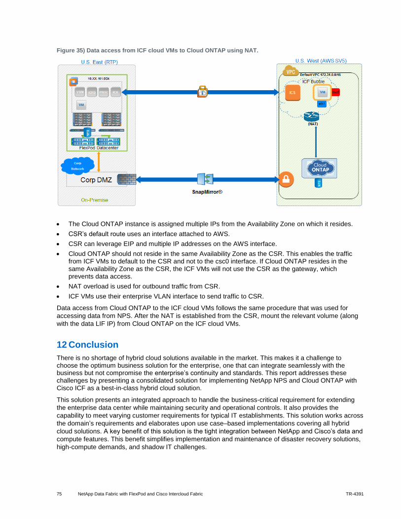
75 NetApp Data Fabric with FlexPod and Cisco Intercloud Fabric TR-4391
Figure 35) Data access from ICF cloud VMs to Cloud ONTAP using NAT.
The Cloud ONTAP instance is assigned multiple IPs from the Availability Zone on which it resides.
CSR’s default route uses an interface attached to AWS.
CSR can leverage EIP and multiple IP addresses on the AWS interface.
Cloud ONTAP should not reside in the same Availability Zone as the CSR. This enables the traffic from ICF VMs to default to the CSR and not to the csc0 interface. If Cloud ONTAP resides in the same Availability Zone as the CSR, the ICF VMs will not use the CSR as the gateway, which prevents data access.
NAT overload is used for outbound traffic from CSR.
ICF VMs use their enterprise VLAN interface to send traffic to CSR.
Data access from Cloud ONTAP to the ICF cloud VMs follows the same procedure that was used for
accessing data from NPS. After the NAT is established from the CSR, mount the relevant volume (along
with the data LIF IP) from Cloud ONTAP on the ICF cloud VMs.
12 Conclusion
There is no shortage of hybrid cloud solutions available in the market. This makes it a challenge to choose the optimum business solution for the enterprise, one that can integrate seamlessly with the business but not compromise the enterprise’s continuity and standards. This report addresses these challenges by presenting a consolidated solution for implementing NetApp NPS and Cloud ONTAP with Cisco ICF as a best-in-class hybrid cloud solution.
This solution presents an integrated approach to handle the business-critical requirement for extending
the enterprise data center while maintaining security and operational controls. It also provides the
capability to meet varying customer requirements for typical IT establishments. This solution works across
the domain’s requirements and elaborates upon use case–based implementations covering all hybrid
cloud solutions. A key benefit of this solution is the tight integration between NetApp and Cisco’s data and
compute features. This benefit simplifies implementation and maintenance of disaster recovery solutions,
high-compute demands, and shadow IT challenges.

76 NetApp Data Fabric with FlexPod and Cisco Intercloud Fabric TR-4391
Acknowledgements
The authors would like to thank the following individuals for their contribution to this report.
Mark Beaupre, NetApp
Jim Holl, NetApp
Kevin Hill, NetApp
John Fullbright, NetApp
Dileep Devireddy, Cisco Systems

77 NetApp Data Fabric with FlexPod and Cisco Intercloud Fabric TR-4391
Refer to the Interoperability Matrix Tool (IMT) on the NetApp Support site to validate that the exact product and feature versions described in this document are supported for your specific environment. The NetApp IMT defines the product components and versions that can be used to construct configurations that are supported by NetApp. Specific results depend on each customer's installation in accordance with published specifications.
Trademark Information
NetApp, the NetApp logo, Go Further, Faster, ASUP, AutoSupport, Campaign Express, Cloud ONTAP, Customer Fitness, Data ONTAP, DataMotion, Fitness, Flash Accel, Flash Cache, Flash Pool, FlashRay, FlexArray, FlexCache, FlexClone, FlexPod, FlexScale, FlexShare, FlexVol, FPolicy, GetSuccessful, LockVault, Manage ONTAP, Mars, MetroCluster, MultiStore, NetApp Insight, OnCommand, ONTAP, ONTAPI, RAID DP, SANtricity, SecureShare, Simplicity, Simulate ONTAP, Snap Creator, SnapCopy, SnapDrive, SnapIntegrator, SnapLock, SnapManager, SnapMirror, SnapMover, SnapProtect, SnapRestore, Snapshot, SnapValidator, SnapVault, StorageGRID, Tech OnTap, Unbound Cloud, and WAFL are trademarks or registered trademarks of NetApp, Inc., in the United States and/or other countries. A current list of NetApp trademarks is available on the Web at http://www.netapp.com/us/legal/netapptmlist.aspx.
Cisco and the Cisco logo are trademarks of Cisco in the U.S. and other countries. All other brands or products are trademarks or registered trademarks of their respective holders and should be treated as such. TR-4391-0315
Copyright Information
Copyright © 1994–2015 NetApp, Inc. All rights reserved. Printed in the U.S. No part of this document covered by copyright may be reproduced in any form or by any means—graphic, electronic, or mechanical, including photocopying, recording, taping, or storage in an electronic retrieval system—without prior written permission of the copyright owner.
Software derived from copyrighted NetApp material is subject to the following license and disclaimer:
THIS SOFTWARE IS PROVIDED BY NETAPP "AS IS" AND WITHOUT ANY EXPRESS OR IMPLIED WARRANTIES, INCLUDING, BUT NOT LIMITED TO, THE IMPLIED WARRANTIES OF MERCHANTABILITY AND FITNESS FOR A PARTICULAR PURPOSE, WHICH ARE HEREBY DISCLAIMED. IN NO EVENT SHALL NETAPP BE LIABLE FOR ANY DIRECT, INDIRECT, INCIDENTAL, SPECIAL, EXEMPLARY, OR CONSEQUENTIAL DAMAGES (INCLUDING, BUT NOT LIMITED TO, PROCUREMENT OF SUBSTITUTE GOODS OR SERVICES; LOSS OF USE, DATA, OR PROFITS; OR BUSINESS INTERRUPTION) HOWEVER CAUSED AND ON ANY THEORY OF LIABILITY, WHETHER IN CONTRACT, STRICT LIABILITY, OR TORT (INCLUDING NEGLIGENCE OR OTHERWISE) ARISING IN ANY WAY OUT OF THE USE OF THIS SOFTWARE, EVEN IF ADVISED OF THE POSSIBILITY OF SUCH DAMAGE.
NetApp reserves the right to change any products described herein at any time, and without notice. NetApp assumes no responsibility or liability arising from the use of products described herein, except as expressly agreed to in writing by NetApp. The use or purchase of this product does not convey a license under any patent rights, trademark rights, or any other intellectual property rights of NetApp.
The product described in this manual may be protected by one or more U.S. patents, foreign patents, or pending applications.
RESTRICTED RIGHTS LEGEND: Use, duplication, or disclosure by the government is subject to restrictions as set forth in subparagraph (c)(1)(ii) of the Rights in Technical Data and Computer Software clause at DFARS 252.277-7103 (October 1988) and FAR 52-227-19 (June 1987).