Embed Size (px)
Citation preview
NetApp Verified Architecture
FlexPod Datacenter with NetApp All-Flash FAS and VMware Horizon (with View)
NVA Design
Eric Railine, NetApp
October 2014 | NVA-1110-FP-DESIGN | Version 1.0
Telephone: +1 (408) 822-6000 Fax: +1 (408) 822-4501 Support telephone: +1 (888) 463-8277 Web: www.netapp.com Feedback: [email protected]
NetApp, Inc. 495 East Java Drive Sunnyvale, CA 94089 U.S.
2 FlexPod Datacenter with NetApp All-Flash FAS and VMware Horizon (with View) © 2014 NetApp, Inc. All Rights Reserved.
TABLE OF CONTENTS
1 Executive Summary.............................................................................................................................. 4
2 Program Summary................................................................................................................................ 4
2.1 FlexPod Program Benefits ..............................................................................................................................5
3 Solution Overview ................................................................................................................................ 7
3.1 Target Audience ..............................................................................................................................................8
3.2 Solution Technology .......................................................................................................................................8
3.3 Use Case Summary ...................................................................................................................................... 23
4 Technology Components .................................................................................................................. 23
4.1 Hardware Components ................................................................................................................................. 23
4.2 Software Components .................................................................................................................................. 24
5 Solution Design .................................................................................................................................. 25
5.1 Cisco UCS Design ........................................................................................................................................ 26
5.2 Cisco Nexus Network Design ........................................................................................................................ 30
5.3 NetApp FAS Storage Design ........................................................................................................................ 33
5.4 VMware vSphere Design .............................................................................................................................. 37
5.5 VMware Horizon with View Design ............................................................................................................... 42
6 Solution Verification ........................................................................................................................... 47
7 Best Practices ..................................................................................................................................... 48
8 Conclusion .......................................................................................................................................... 49
Acknowledgements .................................................................................................................................. 50
References ................................................................................................................................................. 50
Cisco UCS ............................................................................................................................................................ 50
Cisco Nexus Networking ...................................................................................................................................... 50
NetApp FAS Storage ............................................................................................................................................ 50
VMware vSphere .................................................................................................................................................. 51
VMware Horizon View .......................................................................................................................................... 51
Interoperability Matrices ....................................................................................................................................... 51
Version History ......................................................................................................................................... 52
LIST OF TABLES
Table 1) Hardware components. .................................................................................................................................. 24
Table 2) Solution software components. ...................................................................................................................... 25
3 FlexPod Datacenter with NetApp All-Flash FAS and VMware Horizon (with View) © 2014 NetApp, Inc. All Rights Reserved.
Table 3) B-Series M3 FEX 2204XP and 2208XP options. ............................................................................................ 30
Table 4) NetApp FAS8000 storage system technical specifications. ............................................................................ 36
Table 5) NetApp VSC VM configuration. ...................................................................................................................... 37
Table 6) VMware vCenter Server VM configuration. .................................................................................................... 41
Table 7) Microsoft SQL Server database VM configuration.......................................................................................... 41
Table 8) VMware Horizon View Connection VM example configuration. ...................................................................... 43
Table 9) Horizon View Composer VM example configuration. ..................................................................................... 44
Table 10) Virtual desktop configuration. ....................................................................................................................... 47
Table 11) VDI best practices. ....................................................................................................................................... 48
LIST OF FIGURES
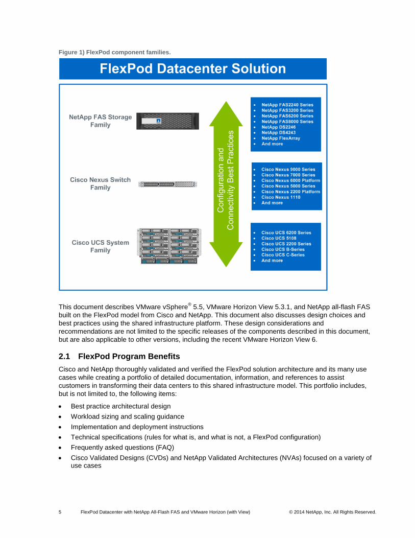
Figure 1) FlexPod component families. ..........................................................................................................................5
Figure 2) FlexPod: Distinct uplink design with clustered Data ONTAP. ..........................................................................9
Figure 3) Cisco UCS Manager. .................................................................................................................................... 12
Figure 4) Clustered Data ONTAP. ................................................................................................................................ 15
Figure 5) NetApp VSC example. .................................................................................................................................. 19
Figure 6) VMware vSphere feature overview. .............................................................................................................. 21
Figure 7) VMware Horizon View deployment (graphic supplied by VMware). .............................................................. 22
Figure 8) VMware Horizon View linked clone using View Composer. .......................................................................... 23
Figure 9) FlexPod distinct uplink design: Cisco UCS B-Series and Cisco Nexus 5500 focus. ..................................... 26
Figure 10) Cisco UCS B-Series M3 Server chassis backplane connections. ............................................................... 27
Figure 11) Example of discrete and port channel modes. ............................................................................................ 28
Figure 12) Cisco UCS backplane configurations—VIC 1240 only. ............................................................................... 29
Figure 13) Validated UCS backplane configuration—VIC1240 with port extender. ...................................................... 29
Figure 14) Scale-out storage with clustered Data ONTAP on FAS. ............................................................................. 34
Figure 15) Distributed storage clusters. ........................................................................................................................ 34
Figure 16) Clustered Data ONTAP in a SAN-only environment. .................................................................................. 35
Figure 17) Clustered Data ONTAP in a NAS-only environment. .................................................................................. 35
Figure 18) Multipath HA to DS2246 shelves of SSD. ................................................................................................... 37
Figure 19) Cisco Nexus 1000v architecture.................................................................................................................. 39
Figure 20) Horizon View architecture. .......................................................................................................................... 42
Figure 21) Horizon View architecture with all-flash FAS and hybrid FAS. .................................................................... 46
4 FlexPod Datacenter with NetApp All-Flash FAS and VMware Horizon (with View) © 2014 NetApp, Inc. All Rights Reserved.
1 Executive Summary
Industry trends indicate a vast data center transformation toward shared infrastructure and cloud
computing, including a growing use of desktop virtualization. Enterprise customers are moving away from
silos of IT operation toward more cost-effective virtualized environments, leading eventually to cloud
computing to increase agility and reduce costs. This transformation appears daunting and complex
because companies must address resistance to change in both their organizational and their technical IT
models. In addition, correctly architecting, deploying, and managing a virtual desktop infrastructure (VDI)
can be challenging because of the large number of solution components in the architecture. To accelerate
this process and enable customers to successfully meet these challenges and gain the numerous
benefits available from a VDI solution, Cisco and NetApp developed a solution for VMware® Horizon
™
with View™
on FlexPod® Datacenter.
The criteria for determining the success of a VDI implementation include the end-user experience. The
end-user experience must be as good as or better than any previous experiences on a physical PC or
virtual desktop. Storage is often the leading cause of the end-user performance problems. The NetApp®
all-flash FAS solution with the FAS8000 platform solves the performance problems commonly found in
VDI deployments. Deployed as part of the FlexPod integrated infrastructure, it allows customers to scale
as needed, keep users from being interrupted, and lessen the risk to business.
When an infrastructure failure prevents users from working, the inactivity translates to lost revenue and
productivity. That is why what used to be considered a tier 3 and 4 application is more critical to business
operations. Having an integrated infrastructure with a robust set of data management and availability
features is key to keeping the users working and lessens the risk to the business. NetApp FlexPod has
multiple built-in features to help improve availability: active-active high availability (HA) across the entire
stack of compute, network, and storage; network and storage quality of service (QoS); multiple and
redundant connections from the servers all the way through the network to the back-end connectivity
between the storage controllers and disks; and nondisruptive operations to seamlessly move virtual
machines (VMs) between hosts in the compute cluster or move either VM or user data within the storage
cluster without impacting the user.
FlexPod also provides the ability to easily increase compute or storage system capacity by simply adding
servers, chassis, disks, or shelves as the business needs dictate. There is no need to purchase additional
compute or storage controllers in order to add users when additional capacity is required. When the
platform requires expansion, additional nodes can be added in a scale-out fashion and managed within
the same management framework and interface. Workloads can then be nondisruptively and seamlessly
migrated or balanced to the new nodes in the cluster (compute or storage).
2 Program Summary
FlexPod is a predesigned, best practice data center architecture that is built on the Cisco® Unified
Computing System™
(Cisco UCS®), the Cisco Nexus
® family of switches, and NetApp fabric-attached
storage (FAS) series systems. FlexPod is a suitable platform for running a variety of virtualization
hypervisors as well as bare-metal operating systems (OSs) and enterprise workloads. FlexPod delivers a
baseline configuration and also has the flexibility to be sized and optimized to accommodate many
different use cases and requirements.
5 FlexPod Datacenter with NetApp All-Flash FAS and VMware Horizon (with View) © 2014 NetApp, Inc. All Rights Reserved.
Figure 1) FlexPod component families.
This document describes VMware vSphere® 5.5, VMware Horizon View 5.3.1, and NetApp all-flash FAS
built on the FlexPod model from Cisco and NetApp. This document also discusses design choices and
best practices using the shared infrastructure platform. These design considerations and
recommendations are not limited to the specific releases of the components described in this document,
but are also applicable to other versions, including the recent VMware Horizon View 6.
2.1 FlexPod Program Benefits
Cisco and NetApp thoroughly validated and verified the FlexPod solution architecture and its many use
cases while creating a portfolio of detailed documentation, information, and references to assist
customers in transforming their data centers to this shared infrastructure model. This portfolio includes,
but is not limited to, the following items:
Best practice architectural design
Workload sizing and scaling guidance
Implementation and deployment instructions
Technical specifications (rules for what is, and what is not, a FlexPod configuration)
Frequently asked questions (FAQ)
Cisco Validated Designs (CVDs) and NetApp Validated Architectures (NVAs) focused on a variety of use cases
6 FlexPod Datacenter with NetApp All-Flash FAS and VMware Horizon (with View) © 2014 NetApp, Inc. All Rights Reserved.
Cisco and NetApp also built a robust and experienced support team focused on FlexPod solutions, from
customer account and technical sales representatives to professional services and technical support
engineers. The support alliance provided by NetApp and Cisco provides customers and channel services
partners with direct access to technical experts who collaborate with cross vendors and have access to
shared lab resources to resolve potential issues.
FlexPod supports tight integration with virtualized and cloud infrastructures, making it the logical choice
for long-term investment. As a key FlexPod Cooperative Support Partner, VMware provides the
virtualization hypervisor and the virtual desktop management solution for this verified design with VMware
vSphere, VMware vCenter, and VMware Horizon with View.
Integrated System
FlexPod is a prevalidated infrastructure that brings together compute, storage, and network to simplify,
accelerate, and minimize the risk associated with data center builds and application rollouts. These
integrated systems provide a standardized approach in the data center that facilitates staff expertise,
application on-boarding, and automation as well as operational efficiencies relating to compliance and
certification.
Fabric Infrastructure Resilience
FlexPod is a highly available and scalable infrastructure that IT can evolve over time to support multiple
physical and virtual application workloads. FlexPod has no single point of failure at any level, from the
server through the network, to the storage. The fabric is fully redundant and scalable and provides
seamless traffic failover, if an individual component fails at the physical or virtual layer.
Fabric Convergence
FlexPod components are interconnected through the Cisco Unified Fabric network architecture, which
supports both traditional LAN traffic and all types of storage traffic, including the lossless requirements for
block-level storage transport using Fibre Channel (FC) or Fibre Channel over Ethernet (FCoE). The Cisco
Unified Fabric provides high-performance, low-latency, and highly available networks, serving a diverse
set of data center needs.
FlexPod uses the Cisco Unified Fabric to offer a wire-once environment that accelerates application
deployment as well as offers efficiencies associated with infrastructure consolidation, including the
following:
Cost savings from the reduction in switches (LAN/SAN switch ports), associated cabling, rack space (capex), and associated power and cooling (opex)
Migration to faster 10GbE network and to 40GbE and 100GbE in the future
Evolution to a converged network with little disruption and preservation of investments in the existing infrastructure, management tools, and staff training (expertise)
Simplified cabling, provisioning, and network maintenance to improve productivity and operational models
Network Virtualization
FlexPod delivers the capability to securely connect VMs into the network. This solution allows network
policies and services to be uniformly applied within the integrated compute stack using technologies such
as virtual LANs (VLANs), QoS, and the Cisco Nexus 1000v virtual distributed switch. This capability
enables the full utilization of FlexPod while maintaining consistent application and security policy
enforcement across the stack even with workload mobility.
7 FlexPod Datacenter with NetApp All-Flash FAS and VMware Horizon (with View) © 2014 NetApp, Inc. All Rights Reserved.
FlexPod provides a uniform approach to IT architecture, offering a well-characterized and -documented
shared pool of resources for application workloads. FlexPod delivers operational efficiency and
consistency with the versatility to meet a variety of SLAs and IT initiatives, including:
Application rollouts or application migrations
Business continuity and disaster recovery (DR)
Desktop virtualization
Cloud delivery models (public, private, hybrid) and service models (IaaS, PaaS, SaaS)
Asset consolidation and virtualization
Data center consolidation/footprint reduction
Flash-Accelerated Storage
The adoption of flash-accelerated storage is a growing trend in the industry. The benefits gained from
flash technologies are well aligned with those of shared infrastructures. With shared infrastructures the
benefits of rapid time to market, ability to scale in consumable increments, reduced risk, and so on are all
derived from a standardized approach to infrastructure design. When deploying flash technologies, it is
important to consider the portfolio breadth of the storage vendor. With NetApp offering proven
technologies such as NetApp Flash Cache
™, Flash Pool
™ intelligent caching and now all-flash FAS,
customers have confidence in deploying a solution that yields known performance characteristics for even
the most demanding workloads.
3 Solution Overview
As customers begin their journey toward VDIs, they face a number of questions, such as:
How do I start the transition?
What will be my return on investment (ROI)?
How do I build a future-proof infrastructure?
How do I cost-effectively transition from my current infrastructure?
Will my applications run properly in a virtual desktop environment?
How do I manage the infrastructure?
What flash options are available to provide equivalent or better performance to that of a physical desktop?
The FlexPod architecture is designed to help with proven guidance and measurable value. By introducing
standardization, FlexPod helps customers mitigate the risk and uncertainty involved in planning,
designing, and implementing a new data center infrastructure. The result is a more predictable and an
adaptable architecture capable of meeting and exceeding customers’ IT demands.
This FlexPod design also provides an opportunity to discuss the various flash topologies that are
available for customer installations. Flash and its capabilities are often highlighted in product
documentation as methods to accelerate application or desktop performance. Some of the questions that
customers face that relate to flash include:
What are the acceptable latencies for virtual desktops?
What are the capacity requirements for the VDI?
Do you prefer flash to be internal to the storage controller or is it acceptable to add flash with external shelves?
What is the life of the proposed infrastructure and should future growth be taken into account with respect to controller expandability, rack space needs, power and cooling requirements, and so on?
8 FlexPod Datacenter with NetApp All-Flash FAS and VMware Horizon (with View) © 2014 NetApp, Inc. All Rights Reserved.
3.1 Target Audience
The intended audience of this document includes, but is not limited to, sales engineers, field consultants,
professional services personnel, IT managers, partner engineering personnel, and customers who want
to take advantage of an infrastructure built to deliver virtual desktop efficiency and enable employee
productivity and innovation.
3.2 Solution Technology
FlexPod is a best practice data center architecture that includes three core components:
Cisco UCS
Cisco Nexus switches
NetApp FAS systems
These components are connected and configured according to best practices of both Cisco and NetApp
and provide the ideal platform for running a variety of enterprise workloads with confidence. FlexPod can
scale up for greater performance and capacity (adding compute, network, or storage resources
individually as needed), or it can scale out for environments that need multiple consistent deployments
(rolling out additional FlexPod stacks). FlexPod delivers a baseline configuration and also has the
flexibility to be sized and optimized to accommodate many different use cases.
Typically, the more scalable and flexible a solution is, the more difficult it becomes to maintain a single
unified architecture capable of offering the same features and functionality across implementations. This
is one of the key benefits of FlexPod. Each of the component families shown in Figure 1 offers platform
and resource options to scale the infrastructure up or down while supporting the same features and
functionality that are required under the configuration and connectivity best practices of FlexPod.
FlexPod addresses four primary design principles: availability, scalability, flexibility, and manageability.
These architecture goals are as follows:
Application availability. Enables services to be accessible and ready to use.
Scalability. Addresses increasing demands with appropriate resources.
Flexibility. Provides new services or recovers resources without infrastructure modification requirements.
Manageability. Facilitates efficient infrastructure operations through open standards and application-programming interface (APIs).
FlexPod: Distinct Uplink Design
Figure 2 details the FlexPod distinct uplink design with the NetApp clustered Data ONTAP® operating
system. As illustrated, the design is fully redundant in the compute, network, and storage layers. There is
no single point of failure from the perspective of a device or traffic path.
9 FlexPod Datacenter with NetApp All-Flash FAS and VMware Horizon (with View) © 2014 NetApp, Inc. All Rights Reserved.
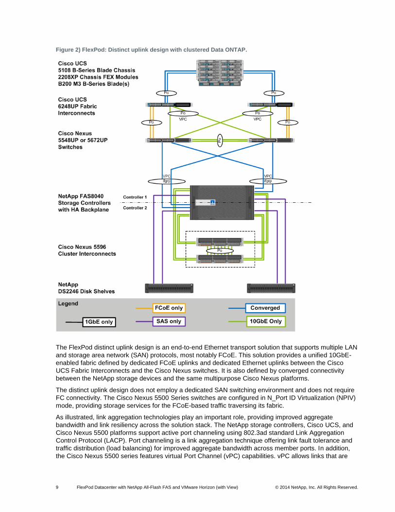
Figure 2) FlexPod: Distinct uplink design with clustered Data ONTAP.
The FlexPod distinct uplink design is an end-to-end Ethernet transport solution that supports multiple LAN
and storage area network (SAN) protocols, most notably FCoE. This solution provides a unified 10GbE-
enabled fabric defined by dedicated FCoE uplinks and dedicated Ethernet uplinks between the Cisco
UCS Fabric Interconnects and the Cisco Nexus switches. It is also defined by converged connectivity
between the NetApp storage devices and the same multipurpose Cisco Nexus platforms.
The distinct uplink design does not employ a dedicated SAN switching environment and does not require
FC connectivity. The Cisco Nexus 5500 Series switches are configured in N_Port ID Virtualization (NPIV)
mode, providing storage services for the FCoE-based traffic traversing its fabric.
As illustrated, link aggregation technologies play an important role, providing improved aggregate
bandwidth and link resiliency across the solution stack. The NetApp storage controllers, Cisco UCS, and
Cisco Nexus 5500 platforms support active port channeling using 802.3ad standard Link Aggregation
Control Protocol (LACP). Port channeling is a link aggregation technique offering link fault tolerance and
traffic distribution (load balancing) for improved aggregate bandwidth across member ports. In addition,
the Cisco Nexus 5500 series features virtual Port Channel (vPC) capabilities. vPC allows links that are
10 FlexPod Datacenter with NetApp All-Flash FAS and VMware Horizon (with View) © 2014 NetApp, Inc. All Rights Reserved.
physically connected to two different Cisco Nexus 5500 Series devices to appear as a single “logical” port
channel to a third device, offering device fault tolerance. vPC addresses aggregate bandwidth, link, and
device resiliency. The Cisco UCS Fabric Interconnects and NetApp FAS controllers benefit from the Cisco
Nexus vPC abstraction, gaining link and device resiliency as well as full utilization of a nonblocking
Ethernet fabric.
The Spanning Tree protocol does not actively block redundant physical links in a properly configured
vPC-enabled environment, so all ports forward the vPC member ports.
This dedicated uplink design leverages FCoE-capable NetApp FAS controllers. From a storage traffic
perspective, both standard LACP and Cisco vPC link aggregation technologies play an important role in
the FlexPod distinct uplink design. Figure 2 illustrates the use of dedicated FCoE uplinks between the
Cisco UCS Fabric Interconnects and Cisco Nexus 5500 unified switches. The Cisco UCS Fabric
Interconnects operate in the N-Port Virtualization (NPV) mode, meaning the servers’ FC traffic is either
manually or automatically pinned to a specific FCoE uplink, in this case either of the two FCoE port
channels. The use of discrete FCoE port channels with distinct VSANs allows an organization to maintain
traditional SAN A/B fabric separation best practices, including separate zone databases. vPC links
between the Cisco Nexus 5500 and NetApp storage controllers’ unified target adapters (UTAs) are
converged, supporting both FCoE and traditional Ethernet traffic at 10GbE. They provide a robust
connection between initiator and target.
Figure 2 shows the initial storage configuration of this solution as a two-node HA pair with clustered Data
ONTAP. An HA pair consists of like storage nodes such as FAS22xx, 32xx, 62xx, or 80xx series.
Scalability is achieved by adding storage capacity (disk/shelves) to an existing HA pair, or by adding HA
pairs into the cluster or storage domain. For SAN environments, the NetApp clustered Data ONTAP
offering allows up to four HA pairs that include eight clustered nodes to form a single logical entity and a
large resource pool of storage that can be easily managed, logically carved, and efficiently consumed.
For network-attached storage (NAS) environments, up to 24 nodes can be configured. In both scenarios,
the HA interconnect allows each HA node pair to assume control of its partner’s storage (disk/shelves)
directly. The local physical HA storage failover capability does not extend beyond the HA pair.
Furthermore, a cluster of nodes does not have to include similar hardware. Rather, individual nodes in an
HA pair are configured alike, allowing customers to scale as needed as they bring additional HA pairs into
the larger cluster.
Network failover is independent of the HA interconnect. Network failover of each node in the cluster is
supported by both the interconnect and switching fabric, permitting cluster and data and management
network interfaces to fail over to different nodes in the cluster, which extends beyond the HA pair.
Using clustered Data ONTAP 8.2 or later, NetApp storage systems can be configured to operate without
the cluster interconnect switches when deploying a two-node storage system. This configuration is
referred to as a “two-node switchless cluster,” and the verification effort for this design used this
configuration.
The following components are required to deploy the distinct uplink design:
Cisco UCS
Cisco Nexus 5X00 Series switch
Cisco Nexus 5596 switch (optional cluster interconnect for 2-node clusters; required for 4+ nodes)
NetApp Unified Storage capable of supporting FCoE storage target adapters
VMware vSphere
Cisco UCS
The Cisco UCS is a next-generation solution for blade and rack server computing. Cisco UCS is an
innovative data center platform that unites compute, network, storage access, and virtualization into a
cohesive system designed to reduce total cost of ownership (TCO) and increase business agility. The
11 FlexPod Datacenter with NetApp All-Flash FAS and VMware Horizon (with View) © 2014 NetApp, Inc. All Rights Reserved.
system integrates a low-latency, lossless 10GbE unified network fabric with enterprise-class, x86-
architecture servers. The system is an integrated, scalable, multichassis platform in which all resources
participate in a unified management domain. Managed as a single system whether it has 2 servers or 160
servers with thousands of VMs, the Cisco UCS decouples scale from complexity. The Cisco UCS
accelerates the delivery of new services simply, reliably, and securely through end-to-end provisioning
and migration support for both virtualized and nonvirtualized systems.
The Cisco UCS consists of the following components:
Cisco UCS Manager provides unified, embedded management of all software and hardware components in the Cisco UCS.
Cisco UCS 6200 Series Fabric Interconnects is a family of line-rate, low-latency, lossless, 10Gbps Ethernet and FCoE interconnect switches providing the management and communication backbone for the UCS.
Cisco UCS 5100 Series Blade Server Chassis supports up to eight blade servers and up to two fabric extenders in a six-rack-unit (RU) enclosure.
Cisco UCS B-Series Blade Servers http://www.cisco.com/c/en/us/products/servers-unified-computing/ucs-b-series-blade-servers/index.html increase performance, efficiency, versatility, and productivity with these Intel
®-based blade servers.
Cisco UCS C-Series Rack Mount Server http://www.cisco.com/en/US/products/ps10493/index.html delivers unified computing in an industry-standard form factor to reduce TCO and increase agility.
Cisco UCS Adapters wire-once architecture offers a range of options to converge the fabric, optimize virtualization, and simplify management.
For more information about Cisco UCS, refer to the Cisco Servers - Unified Computing site.
Cisco UCS Manager
Cisco UCS Manager provides unified, centralized, embedded management of all Cisco UCS software and
hardware components across multiple chassis and thousands of VMs. Administrators use the software to
manage the entire Cisco UCS as a single logical entity through an intuitive GUI, a command-line interface
(CLI), or an XML API.
The Cisco UCS Manager resides on a pair of Cisco UCS 6200 Series Fabric Interconnects using a
clustered, active-standby configuration for HA. The software gives administrators a single interface for
performing server provisioning, device discovery, inventory, configuration, diagnostics, monitoring, fault
detection, auditing, and statistics collection. Cisco UCS Manager service profiles and templates support
versatile role- and policy-based management, and system configuration information can be exported to
configuration management databases to facilitate processes based on IT Infrastructure Library concepts.
Compute nodes are deployed in a Cisco UCS environment by leveraging Cisco UCS service profiles.
Service profiles let server, network, and storage administrators treat Cisco UCS servers as raw computing
capacity to be allocated and reallocated as needed. The profiles define server input/output (I/O)
properties, personalities, properties, and firmware revisions and are stored in the Cisco UCS 6200 Series
Fabric Interconnects. Using service profiles, administrators can provision infrastructure resources in
minutes instead of days, creating a more dynamic environment and more efficient use of server capacity.
Each service profile consists of a server software definition and the server’s LAN and SAN connectivity
requirements. When a service profile is deployed to a server, Cisco UCS Manager automatically
configures the server, adapters, fabric extenders, and fabric interconnects to match the configuration
specified in the profile. The automatic configuration of servers, network interface cards (NICs), host bus
adapters (HBAs), and LAN and SAN switches lowers the risk of human error, improves consistency, and
decreases server deployment times.
Service profiles benefit both virtualized and nonvirtualized environments. The profiles increase the
mobility of nonvirtualized servers, such as when moving workloads from server to server or taking a
12 FlexPod Datacenter with NetApp All-Flash FAS and VMware Horizon (with View) © 2014 NetApp, Inc. All Rights Reserved.
server offline for service or upgrade. Profiles can also be used in conjunction with virtualization clusters to
bring new resources online easily, complementing existing VM mobility.
Figure 3) Cisco UCS Manager.
For more information about Cisco UCS Manager, refer to the Cisco Nexus 5000 Series Switches site.
Cisco Nexus 5500 Series Switches
The Cisco Nexus 5500 Series is designed for data center environments with cut-through switching
technology that enables consistent low-latency Ethernet solutions, with front-to-back or back-to-front
cooling, and with data ports in the rear, bringing switching into close proximity with servers and making
cable runs short and simple. The switch series is highly serviceable, with redundant, hot-pluggable power
supplies and fan modules. It uses data center–class Cisco NX-OS software for high reliability and ease of
management.
The Cisco Nexus 5500 platform extends the industry-leading versatility of the Cisco Nexus 5500 Series
purpose-built 10GbE data center–class switches and provides innovative advances toward higher
density, lower latency, and multilayer services. The Cisco Nexus 5500 platform is well suited for
enterprise-class data center server access-layer deployments across a diverse set of physical, virtual,
storage-access, and high-performance computing (HPC) data center environments.
The switch used in this FlexPod architecture is the Cisco Nexus 5548UP. The following specifications
describe the Cisco Nexus 5548UP switch:
A 1-rack unit, 1/10GbE switch
32 fixed Unified Ports on base chassis and 1 expansion slot totaling 48 ports
The slot can support any of the 3 modules: Unified Ports, 1/2/4/8 native FC, and Ethernet or FCoE
Throughput of up to 960Gb/sec
For more information, refer to the Cisco Nexus 5000 Series Switches site.
13 FlexPod Datacenter with NetApp All-Flash FAS and VMware Horizon (with View) © 2014 NetApp, Inc. All Rights Reserved.
NetApp All-Flash FAS
Built on more than 20 years of innovation, Data ONTAP has evolved to meet the changing needs of
customers and help drive their success. NetApp clustered Data ONTAP provides a rich set of data
management features and clustering for scale-out, operational efficiency, and nondisruptive operations to
offer customers one of the most compelling value propositions in the industry. The IT landscape is
undergoing a fundamental shift to IT as a service (ITaaS), a model that requires a pool of compute,
network, and storage to serve a wide range of applications and deliver a wide range of services.
Innovations such as NetApp clustered Data ONTAP are fueling this revolution.
NetApp solutions are user friendly, easy to manage, quick to deploy, and offer increased availability while
consuming fewer IT resources. This means that they dramatically lower the lifetime TCO. Whereas others
manage complexity, NetApp eliminates it. A NetApp solution includes hardware in the form of controllers
and disk storage and the NetApp Data ONTAP OS.
NetApp offers the NetApp Unified Storage Architecture. The term “unified” refers to a family of storage
systems that simultaneously support SAN and NAS across many operating environments such as
VMware, Windows®, and UNIX
®. This single architecture provides access to data by using industry-
standard protocols, including NFS, CIFS, iSCSI, FCP, and FCoE. Connectivity options include standard
Ethernet (10/100/1000, or 10GbE) and FC (1, 2, 4, or 8Gb/sec).
This FlexPod Datacenter solution includes the NetApp FAS8000 series unified scale-out storage systems.
Powered by NetApp Data ONTAP, the FAS8000 series unifies the SAN and NAS storage infrastructure.
The FAS8000 features a multiprocessor Intel chipset and leverages high-performance memory modules,
NVRAM to accelerate and optimize writes, and an I/O-tuned PCIe gen3 architecture that maximizes
application throughput. The FAS8000 series comes with integrated UTA2 ports that support 16Gb FC,
10GbE, or FCoE.
If storage requirements change over time, NetApp storage offers the flexibility to change quickly, as
needed, and without expensive and disruptive “forklift” upgrades. For example, a LUN can be changed
from FC access to iSCSI access without moving or copying the data. Only a simple dismount of the FC
LUN and a mount of the same LUN using iSCSI would be required. In addition, a single copy of data can
be shared between Windows and UNIX systems while allowing each environment to access the data
through native protocols and applications.
NetApp storage solutions provide redundancy and fault tolerance through clustered storage controllers,
hot-swappable redundant components (such as cooling fans, power supplies, disk drives, and shelves),
and multiple network interfaces. This highly available and flexible architecture enables customers to
manage all data under one common infrastructure while achieving mission requirements. The NetApp
Unified Storage Architecture allows data storage with higher availability and performance, easier dynamic
expansion, and more unrivalled ease of management than any other solution.
Outstanding Performance
The NetApp all-flash FAS solution shares the same unified storage architecture, Data ONTAP OS,
management interface, rich data services, and advanced feature set as the rest of the FAS product
families. This unique combination of all-flash media with Data ONTAP delivers the consistent low latency
and high input/output operations per second (IOPS) of all-flash storage, with the industry-leading
clustered Data ONTAP OS. In addition, it offers proven enterprise availability, reliability, and scalability;
storage efficiency proven in thousands of VDI deployments; unified storage with multiprotocol access;
advanced data services; and operational agility through tight application integrations.
Optimized Writes
The NetApp Write Anywhere File Layout® (WAFL)
file system enables NetApp to process writes
efficiently. When the Data ONTAP OS receives an I/O, it stores the I/O in battery-backed nonvolatile RAM
(NVRAM) in both controllers of the HA pair and sends back an acknowledgement (or ACK), notifying the
14 FlexPod Datacenter with NetApp All-Flash FAS and VMware Horizon (with View) © 2014 NetApp, Inc. All Rights Reserved.
sender that the write is committed. Acknowledging the write before committing to disk provides a very low
response time for write I/O and thus low write latency. This architecture also allows Data ONTAP to
perform many functions to optimize the data layout for optimal write/write coalescing. Before being written
to disk, I/Os are coalesced into larger blocks because larger sequential blocks require less CPU for each
operation.
Enhancing Flash
NetApp Data ONTAP has been leveraging flash technologies since 2009 and has supported solid-state
drives (SSDs) since 2010. This relatively long experience in dealing with SSDs has allowed NetApp to
tune Data ONTAP features to optimize SSD performance and enhance flash media endurance.
As described in the previous sections, because Data ONTAP acknowledges writes after they are in
dynamic random-access memory (DRAM) and logged to NVRAM, SSDs are not in the critical write path.
Therefore, write latencies are very low. Data ONTAP also enables efficient use of SSDs when destaging
cache by coalescing writes into a single sequential stripe across all SSDs at once. Data ONTAP writes to
free space whenever possible, minimizing overwrites for every dataset, not only for deduped or
compressed data.
This wear-leveling feature of Data ONTAP is native to the architecture, and it also leverages the wear-
leveling and garbage-collection algorithms built into the SSDs to extend the life of the devices. Therefore,
NetApp provides up to a five-year warranty with all SSDs (three-year standard warranty, plus the offer of
an additional two-year extended warranty, with no restrictions on the number of drive writes).
The parallelism built into Data ONTAP, combined with the multicore CPUs and large system memories in
the NetApp FAS8000 storage controllers, takes full advantage of SSD performance.
NetApp Clustered Data ONTAP
With clustered Data ONTAP, NetApp provides enterprise-ready, unified scale-out storage. Developed
from a solid foundation of proven Data ONTAP technology and innovation, clustered Data ONTAP is the
basis for large virtualized shared storage infrastructures that are architected for nondisruptive operations
over the system lifetime. Controller nodes are deployed in HA pairs, with these HA pairs participating in a
single storage domain or cluster.
NetApp Data ONTAP scale-out is one way to respond to growth in a storage environment. All storage
controllers have physical limits to their expandability: number of CPUs, memory slots, and space for disk
shelves that dictate the maximum capacity and controller performance. If more storage or performance
capacity is needed, it might be possible to add CPUs and memory or install additional disk shelves, but
ultimately the controller becomes completely populated, with no further expansion possible. At this stage
the only option is to acquire another controller. One way to do this is to scale up; that is, to add additional
controllers in such a way that each is a completely independent management entity that does not provide
any shared storage resources. If the original controller is to be completely replaced by the newer and
larger controller, data migration is required to transfer the data from the old controller to the new one. This
is time consuming and potentially disruptive and most likely requires configuration changes on all of the
attached host systems.
If the newer controller can coexist with the original controller, there are now two storage controllers to be
individually managed, and there are no native tools to balance or reassign workloads across them. The
situation becomes worse as the number of controllers increases. If the scale-up approach is used, the
operational burden increases consistently as the environment grows, and the end result is a very
unbalanced and difficult-to-manage environment. Technology refresh cycles require substantial planning
in advance, lengthy outages, and configuration changes, which introduce risk into the system.
By contrast, using scale-out means that as the storage environment grows, additional controllers are
added seamlessly to the resource pool residing on a shared storage infrastructure. Host and client
connections as well as datastores can move seamlessly and nondisruptively anywhere in the resource
15 FlexPod Datacenter with NetApp All-Flash FAS and VMware Horizon (with View) © 2014 NetApp, Inc. All Rights Reserved.
pool, so that existing workloads can be easily balanced over the available resources and new workloads
can be easily deployed. Technology refreshes (replacing disk shelves, adding or completely replacing
storage controllers) are accomplished while the environment remains online and continues serving data.
Although scale-out products have been available for some time, these were typically subject to one or
more of the following shortcomings:
Limited protocol support (NAS only)
Limited hardware support (supported only by a particular type of storage controller or a very limited set)
Little or no storage efficiency (thin provisioning, deduplication, and compression)
Little or no data replication capability
Therefore, while these products are well positioned for certain specialized workloads, they are less
flexible, less capable, and not robust enough for broad deployment throughout the enterprise.
NetApp Data ONTAP is the first product to offer a complete scale-out solution, and it offers an adaptable,
always-available storage infrastructure for today’s highly virtualized environment.
Scale Out
Data centers require agility. In a data center, each storage controller has CPU, memory, and disk shelf
limits. Scale-out means that as the storage environment grows, additional controllers can be added
seamlessly to the resource pool residing on a shared storage infrastructure. Host and client connections
as well as datastores can be moved seamlessly and nondisruptively anywhere within the resource pool.
The benefits of scale-out include the following:
Nondisruptive operations
Ability to keep adding thousands of users to the virtual desktop environment without downtime
Operational simplicity and flexibility
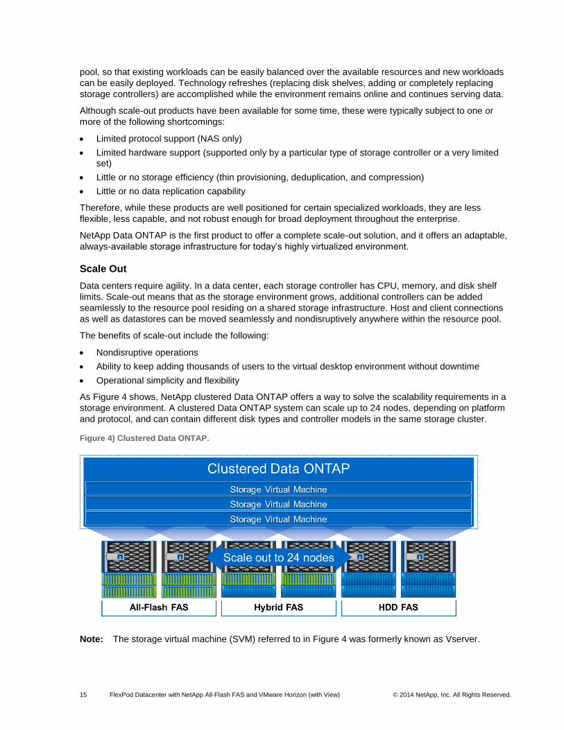
As Figure 4 shows, NetApp clustered Data ONTAP offers a way to solve the scalability requirements in a
storage environment. A clustered Data ONTAP system can scale up to 24 nodes, depending on platform
and protocol, and can contain different disk types and controller models in the same storage cluster.
Figure 4) Clustered Data ONTAP.
Note: The storage virtual machine (SVM) referred to in Figure 4 was formerly known as Vserver.
16 FlexPod Datacenter with NetApp All-Flash FAS and VMware Horizon (with View) © 2014 NetApp, Inc. All Rights Reserved.
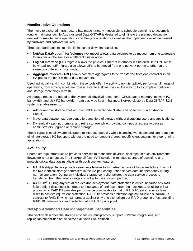
Nondisruptive Operations
The move to a shared infrastructure has made it nearly impossible to schedule downtime to accomplish
routine maintenance. NetApp clustered Data ONTAP is designed to eliminate the planned downtime
needed for maintenance operations and lifecycle operations as well as the unplanned downtime caused
by hardware and software failures.
Three standard tools make this elimination of downtime possible:
NetApp DataMotion™
for Volumes (vol move) allows data volumes to be moved from one aggregate to another on the same or a different cluster node.
Logical interface (LIF) migrate allows the physical Ethernet interfaces in clustered Data ONTAP to be virtualized. LIF migrate also allows LIFs to be moved from one network port to another on the same or a different cluster node.
Aggregate relocate (ARL) allows complete aggregates to be transferred from one controller in an HA pair to the other without data movement.
Used individually and in combination, these tools offer the ability to nondisruptively perform a full range of
operations, from moving a volume from a faster to a slower disk all the way up to a complete controller
and storage technology refresh.
As storage nodes are added to the system, all physical resources—CPUs, cache memory, network I/O
bandwidth, and disk I/O bandwidth—can easily be kept in balance. NetApp clustered Data ONTAP 8.2.1
systems enable users to:
Add or remove storage shelves (over 23PB in an 8-node cluster and up to 69PB in a 24-node cluster).
Move data between storage controllers and tiers of storage without disrupting users and applications.
Dynamically assign, promote, and retire storage while providing continuous access to data as administrators upgrade or replace storage.
These capabilities allow administrators to increase capacity while balancing workloads and can reduce or
eliminate storage I/O hot spots without the need to remount shares, modify client settings, or stop running
applications.
Availability
Shared storage infrastructure provides services to thousands of virtual desktops. In such environments,
downtime is not an option. The NetApp all-flash FAS solution eliminates sources of downtime and
protects critical data against disaster through two key features:
HA. A NetApp HA pair provides seamless failover to its partner in case of hardware failure. Each of the two identical storage controllers in the HA pair configuration serves data independently during normal operation. During an individual storage controller failure, the data service process is transferred from the failed storage controller to the surviving partner.
RAID DP®. During any virtualized desktop deployment, data protection is critical because any RAID
failure might disconnect hundreds to thousands of end users from their desktops, resulting in lost productivity. RAID DP provides performance comparable to that of RAID 10, yet it requires fewer disks to achieve equivalent protection. RAID DP provides protection against double disk failure, in contrast to RAID 5, which can protect against only one disk failure per RAID group, in effect providing RAID 10 performance and protection at a RAID 5 price point.
NetApp Advanced Data Management Capabilities
This section describes the storage efficiencies, multiprotocol support, VMware integrations, and
replication capabilities of the NetApp all-flash FAS solution.
17 FlexPod Datacenter with NetApp All-Flash FAS and VMware Horizon (with View) © 2014 NetApp, Inc. All Rights Reserved.
Storage Efficiencies
Most desktop virtualization implementations deploy thousands of desktops from a small number of golden
VM images, resulting in large amounts of duplicate data. This is especially the case with the VM OS.
The NetApp all-flash FAS solution includes built-in thin provisioning, data deduplication, compression,
and zero-cost cloning with NetApp FlexClone® that offer multilevel storage efficiency across virtual
desktop data, installed applications, and user data. The comprehensive storage efficiency enables a
significantly reduced storage footprint for virtualized desktop implementations, with a capacity reduction of
up to 10:1, or 90% (based on existing customer deployments and NetApp solutions lab verification).
Three features make this storage efficiency possible:
Thin provisioning allows multiple applications to share a single pool of on-demand storage, eliminating the need to provision more storage for one application while another application still has plenty of allocated but unused storage.
Deduplication saves space on primary storage by removing redundant copies of blocks in a volume that hosts hundreds of virtual desktops. This process is transparent to the application and the user, and it can be enabled and disabled on the fly. To eliminate any potential concerns about post-process deduplication causing additional wear on the SSDs, NetApp provides up to a five-year warranty with all SSDs (three-year standard, plus an additional two-year extended warranty), with no restrictions on the number of drive writes.
FlexClone offers hardware-assisted rapid creation of space-efficient, writable, point-in-time images of individual VM files, LUNs, or flexible volumes. It is fully integrated with VMware vSphere vStorage APIs for Array Integration (VAAI). The use of FlexClone technology in VDI deployments provides high levels of scalability and significant cost, space, and time savings. Both file-level cloning and volume-level cloning are tightly integrated with the VMware vCenter
™ Server through the NetApp Virtual
Storage Console (VSC) Provisioning and Cloning vCenter plug-in and native VM cloning offload with VMware VAAI. The NetApp VSC provides the flexibility to rapidly provision and redeploy thousands of VMs with hundreds of VMs in each datastore.
Advanced Storage Features
NetApp Data ONTAP provides a number of additional features that can be leveraged in a virtual desktop
environment, whether for the infrastructure supporting the desktops or the desktops themselves. Some of
these features are:
NetApp Snapshot® copies. Manual or automatically scheduled point-in-time copies that write only
changed blocks, with no performance penalty. Snapshot copies consume minimal storage space because only changes to the active file system are written. Individual files and directories can easily be recovered from any Snapshot copy, and the entire volume can be restored back to any Snapshot state in seconds.
Compression. Compression of data blocks on disk to provide space savings instead of or in addition to those obtained with deduplication.
LIF. A logical interface that is associated to a physical port, interface group (ifgrp), or VLAN interface. More than one LIF can be associated to a physical port at the same time. There are three types of LIFs:
NFS LIF
iSCSI LIF
FC LIF
LIFs are logical network entities that have the same characteristics as physical network devices but are not tied to physical objects. LIFs used for Ethernet traffic are assigned specific Ethernet-based details such as IP addresses and iSCSI-qualified names and are then associated with a specific physical port capable of supporting Ethernet. LIFs used for FC-based traffic are assigned specific FC-based details such as worldwide port names and are then associated with a specific physical port capable of supporting FC or FCoE. NAS LIFs can be nondisruptively migrated to any other physical
18 FlexPod Datacenter with NetApp All-Flash FAS and VMware Horizon (with View) © 2014 NetApp, Inc. All Rights Reserved.
network port throughout the entire cluster at any time, either manually or automatically (by using policies), whereas SAN LIFs rely on multipath input/output (MPIO) and Asymmetric Logical Unit Access (ALUA) to notify clients of any change in the network topology.
SVM (formerly known as Vserver). An SVM is a secure virtual storage server that contains data volumes and one or more LIFs through which it serves data to the clients. An SVM securely isolates the shared virtualized data storage and network and appears as a single dedicated server to its clients. Each SVM has a separate administrator authentication domain and can be managed independently by an SVM administrator.
Multiprotocol Support
By supporting all common NAS and SAN protocols on a single platform, NetApp Unified Storage
enables:
Direct access to storage by each client
Network file sharing across different platforms without the need for protocol-emulation products such as SAMBA, NFS Maestro, or PC-NFS
Simple and fast data storage and data access for all client systems
Fewer storage systems
Greater efficiency from each system deployed
Clustered Data ONTAP can support several protocols concurrently in the same storage system. Data
ONTAP 7G and 7-Mode versions also include support for multiple protocols. Unified storage is important
to VMware Horizon View solutions, such as CIFS/SMB for user data, NFS or SAN for the VM datastores,
and guest-connect iSCSI LUNs for Windows applications.
The following protocols are supported:
NFS v3, v4, and v4.1 (including pNFS)
iSCSI
FC
FCoE
CIFS
VMware vSphere Integrations
The complexity of deploying and managing thousands of virtual desktops can be daunting without the
right tools. NetApp VSC for VMware vSphere is tightly integrated with VMware vCenter for rapidly
provisioning, managing, configuring, and backing up a VMware Horizon with View implementation.
NetApp VSC significantly increases operational efficiency and agility by simplifying the deployment and
management process for thousands of virtual desktops.
The following plug-ins and software features simplify deployment and administration of virtual desktop
environments:
NetApp VSC Provisioning and Cloning plug-in enables customers to rapidly provision, manage, import, and reclaim space of thinly provisioned VMs and redeploy thousands of VMs.
NetApp VSC Backup and Recovery plug-in integrates VMware snapshot functionality with NetApp Snapshot functionality to protect VMware Horizon View environments.
The NetApp VSC software delivers storage configuration and monitoring, datastore provisioning, VM
cloning, and backup and recovery of VMs and datastores. NetApp VSC also includes an API for
automated control. NetApp VSC delivers a single VMware plug-in that provides end-to-end VM lifecycle
management for VMware environments using NetApp storage. NetApp VSC is delivered as a VMware
vCenter Server plug-in. This is different from a client-side plug-in that must be installed on every VMware
19 FlexPod Datacenter with NetApp All-Flash FAS and VMware Horizon (with View) © 2014 NetApp, Inc. All Rights Reserved.
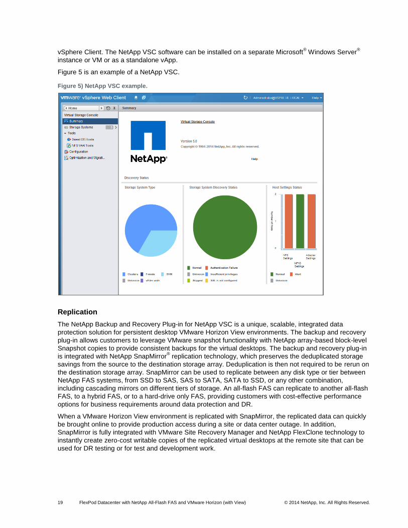
vSphere Client. The NetApp VSC software can be installed on a separate Microsoft® Windows Server
®
instance or VM or as a standalone vApp.
Figure 5 is an example of a NetApp VSC.
Figure 5) NetApp VSC example.
Replication
The NetApp Backup and Recovery Plug-in for NetApp VSC is a unique, scalable, integrated data
protection solution for persistent desktop VMware Horizon View environments. The backup and recovery
plug-in allows customers to leverage VMware snapshot functionality with NetApp array-based block-level
Snapshot copies to provide consistent backups for the virtual desktops. The backup and recovery plug-in
is integrated with NetApp SnapMirror® replication technology, which preserves the deduplicated storage
savings from the source to the destination storage array. Deduplication is then not required to be rerun on
the destination storage array. SnapMirror can be used to replicate between any disk type or tier between
NetApp FAS systems, from SSD to SAS, SAS to SATA, SATA to SSD, or any other combination,
including cascading mirrors on different tiers of storage. An all-flash FAS can replicate to another all-flash
FAS, to a hybrid FAS, or to a hard-drive only FAS, providing customers with cost-effective performance
options for business requirements around data protection and DR.
When a VMware Horizon View environment is replicated with SnapMirror, the replicated data can quickly
be brought online to provide production access during a site or data center outage. In addition,
SnapMirror is fully integrated with VMware Site Recovery Manager and NetApp FlexClone technology to
instantly create zero-cost writable copies of the replicated virtual desktops at the remote site that can be
used for DR testing or for test and development work.
20 FlexPod Datacenter with NetApp All-Flash FAS and VMware Horizon (with View) © 2014 NetApp, Inc. All Rights Reserved.
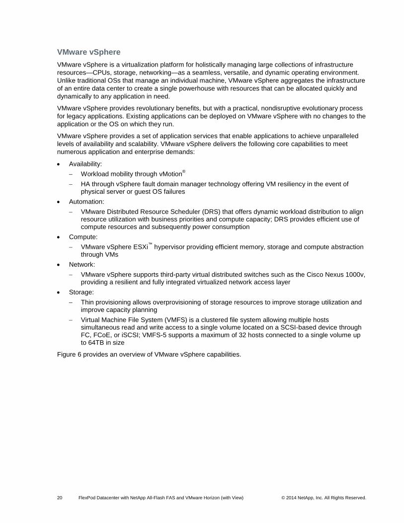
VMware vSphere
VMware vSphere is a virtualization platform for holistically managing large collections of infrastructure
resources—CPUs, storage, networking—as a seamless, versatile, and dynamic operating environment.
Unlike traditional OSs that manage an individual machine, VMware vSphere aggregates the infrastructure
of an entire data center to create a single powerhouse with resources that can be allocated quickly and
dynamically to any application in need.
VMware vSphere provides revolutionary benefits, but with a practical, nondisruptive evolutionary process
for legacy applications. Existing applications can be deployed on VMware vSphere with no changes to the
application or the OS on which they run.
VMware vSphere provides a set of application services that enable applications to achieve unparalleled
levels of availability and scalability. VMware vSphere delivers the following core capabilities to meet
numerous application and enterprise demands:
Availability:
Workload mobility through vMotion®
HA through vSphere fault domain manager technology offering VM resiliency in the event of physical server or guest OS failures
Automation:
VMware Distributed Resource Scheduler (DRS) that offers dynamic workload distribution to align resource utilization with business priorities and compute capacity; DRS provides efficient use of compute resources and subsequently power consumption
Compute:
VMware vSphere ESXi™
hypervisor providing efficient memory, storage and compute abstraction through VMs
Network:
VMware vSphere supports third-party virtual distributed switches such as the Cisco Nexus 1000v, providing a resilient and fully integrated virtualized network access layer
Storage:
Thin provisioning allows overprovisioning of storage resources to improve storage utilization and improve capacity planning
Virtual Machine File System (VMFS) is a clustered file system allowing multiple hosts simultaneous read and write access to a single volume located on a SCSI-based device through FC, FCoE, or iSCSI; VMFS-5 supports a maximum of 32 hosts connected to a single volume up to 64TB in size
Figure 6 provides an overview of VMware vSphere capabilities.
21 FlexPod Datacenter with NetApp All-Flash FAS and VMware Horizon (with View) © 2014 NetApp, Inc. All Rights Reserved.
Figure 6) VMware vSphere feature overview.
The VMware vSphere environment delivers a robust application environment. For example, with VMware
vSphere, all applications can be protected from downtime with VMware HA without the complexity of
conventional clustering. In addition, applications can be scaled dynamically to meet changing loads with
capabilities such as Hot Add and VMware DRS.
For more information, refer to the VMware vSphere product site.
VMware Horizon with View
VMware Horizon with View is an enterprise-class desktop virtualization solution that delivers virtualized or
remote desktops and applications to end users through a single platform. VMware Horizon View allows IT
to manage desktops, applications, and data centrally while increasing flexibility and customization at the
endpoint for the user. It enables levels of availability and agility of desktop services unmatched by
traditional PCs at about half the TCO per desktop.
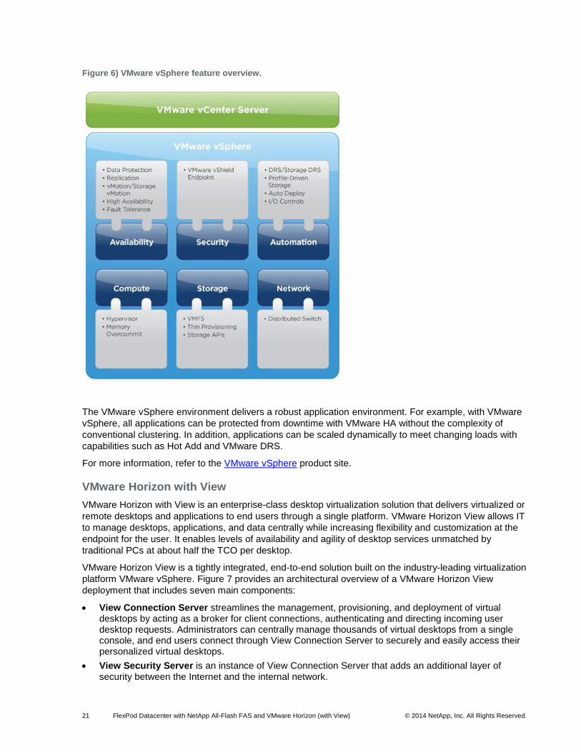
VMware Horizon View is a tightly integrated, end-to-end solution built on the industry-leading virtualization
platform VMware vSphere. Figure 7 provides an architectural overview of a VMware Horizon View
deployment that includes seven main components:
View Connection Server streamlines the management, provisioning, and deployment of virtual desktops by acting as a broker for client connections, authenticating and directing incoming user desktop requests. Administrators can centrally manage thousands of virtual desktops from a single console, and end users connect through View Connection Server to securely and easily access their personalized virtual desktops.
View Security Server is an instance of View Connection Server that adds an additional layer of security between the Internet and the internal network.
22 FlexPod Datacenter with NetApp All-Flash FAS and VMware Horizon (with View) © 2014 NetApp, Inc. All Rights Reserved.
View Composer Server is an optional feature that allows you to manage pools of linked-clones desktops by creating master images that share a common virtual disk.
View Agent service communicates between VMs and Horizon Client. View Agent is installed on all VMs managed by vCenter Server so that View Connection Server can communicate with them. View Agent also provides features such as connection monitoring, virtual printing, persona management, and access to locally connected USB devices. View Agent is installed in the guest OS.
Horizon Clients can be installed on each endpoint device to enable end users to access their virtual desktops from devices such as zero clients, thin clients, Windows PCs, Macs, and iOS-based and Android-based mobile devices. Horizon Clients are available for Windows, Mac
®, Ubuntu, Linux
®,
iOS, and Android to provide the connection to remote desktops from the device of choice.
View Persona Management is an optional feature that provides persistent, dynamic user profiles across user sessions on different desktops. This capability allows you to deploy pools of stateless, floating desktops and enables users to maintain their designated settings between sessions. User profile data is downloaded as needed to speed up login and logout time. New user settings are automatically sent to the user profile repository during desktop use.
ThinApp is an optional software component included with Horizon that creates virtualized applications.
Figure 7) VMware Horizon View deployment (graphic supplied by VMware).
The following sections describe the VMware Horizon View components used in this reference
architecture: VMware Horizon View Connection Server and Horizon View Composer.
VMware Horizon View Connection Server
The VMware Horizon View Connection Server is responsible for provisioning and managing virtual
desktops and for brokering the connections between clients and the virtual desktop machines.
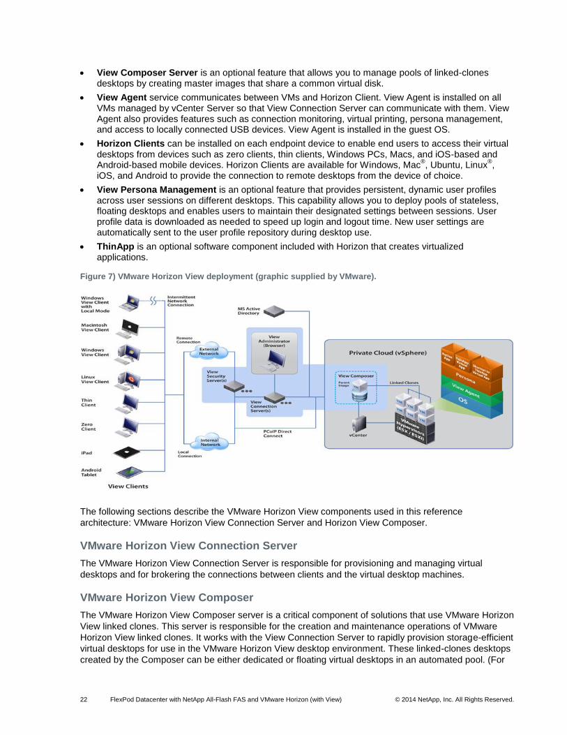
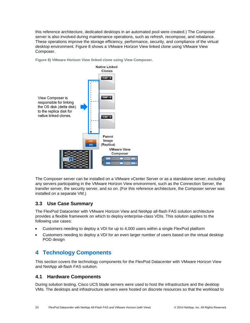
VMware Horizon View Composer
The VMware Horizon View Composer server is a critical component of solutions that use VMware Horizon
View linked clones. This server is responsible for the creation and maintenance operations of VMware
Horizon View linked clones. It works with the View Connection Server to rapidly provision storage-efficient
virtual desktops for use in the VMware Horizon View desktop environment. These linked-clones desktops
created by the Composer can be either dedicated or floating virtual desktops in an automated pool. (For
23 FlexPod Datacenter with NetApp All-Flash FAS and VMware Horizon (with View) © 2014 NetApp, Inc. All Rights Reserved.
this reference architecture, dedicated desktops in an automated pool were created.) The Composer
server is also involved during maintenance operations, such as refresh, recompose, and rebalance.
These operations improve the storage efficiency, performance, security, and compliance of the virtual
desktop environment. Figure 8 shows a VMware Horizon View linked clone using VMware View
Composer.
Figure 8) VMware Horizon View linked clone using View Composer.
The Composer server can be installed on a VMware vCenter Server or as a standalone server, excluding
any servers participating in the VMware Horizon View environment, such as the Connection Server, the
transfer server, the security server, and so on. (For this reference architecture, the Composer server was
installed on a separate VM.)
3.3 Use Case Summary
The FlexPod Datacenter with VMware Horizon View and NetApp all-flash FAS solution architecture
provides a flexible framework on which to deploy enterprise-class VDIs. This solution applies to the
following use cases:
Customers needing to deploy a VDI for up to 4,000 users within a single FlexPod platform
Customers needing to deploy a VDI for an even larger number of users based on the virtual desktop POD design
4 Technology Components
This section covers the technology components for the FlexPod Datacenter with VMware Horizon View
and NetApp all-flash FAS solution.
4.1 Hardware Components
During solution testing, Cisco UCS blade servers were used to host the infrastructure and the desktop
VMs. The desktops and infrastructure servers were hosted on discrete resources so that the workload to
24 FlexPod Datacenter with NetApp All-Flash FAS and VMware Horizon (with View) © 2014 NetApp, Inc. All Rights Reserved.
the NetApp all-flash FAS system could be precisely measured. It is a NetApp and industry best practice to
separate the desktop VMs from the infrastructure VMs because noisy neighbors or bully virtual desktops
can affect the infrastructure, which can negatively impact all users, applications, and performance results.
A separate NetApp FAS storage system (not shown) was used to host the infrastructure and launcher
VMs as well as the boot LUNs from the desktop hosts. This is a typical configuration for a customer
environment.
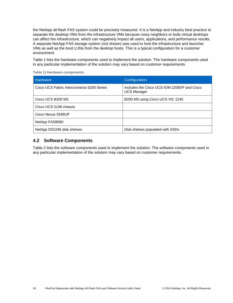
Table 1 lists the hardware components used to implement the solution. The hardware components used
in any particular implementation of the solution may vary based on customer requirements.
Table 1) Hardware components.
Hardware Configuration
Cisco UCS Fabric Interconnects 6200 Series Includes the Cisco UCS-IOM 2208XP and Cisco UCS Manager
Cisco UCS B200 M3 B200 M3 using Cisco UCS VIC 1240
Cisco UCS 5108 chassis
Cisco Nexus 5548UP
NetApp FAS8060
NetApp DS2246 disk shelves Disk shelves populated with SSDs
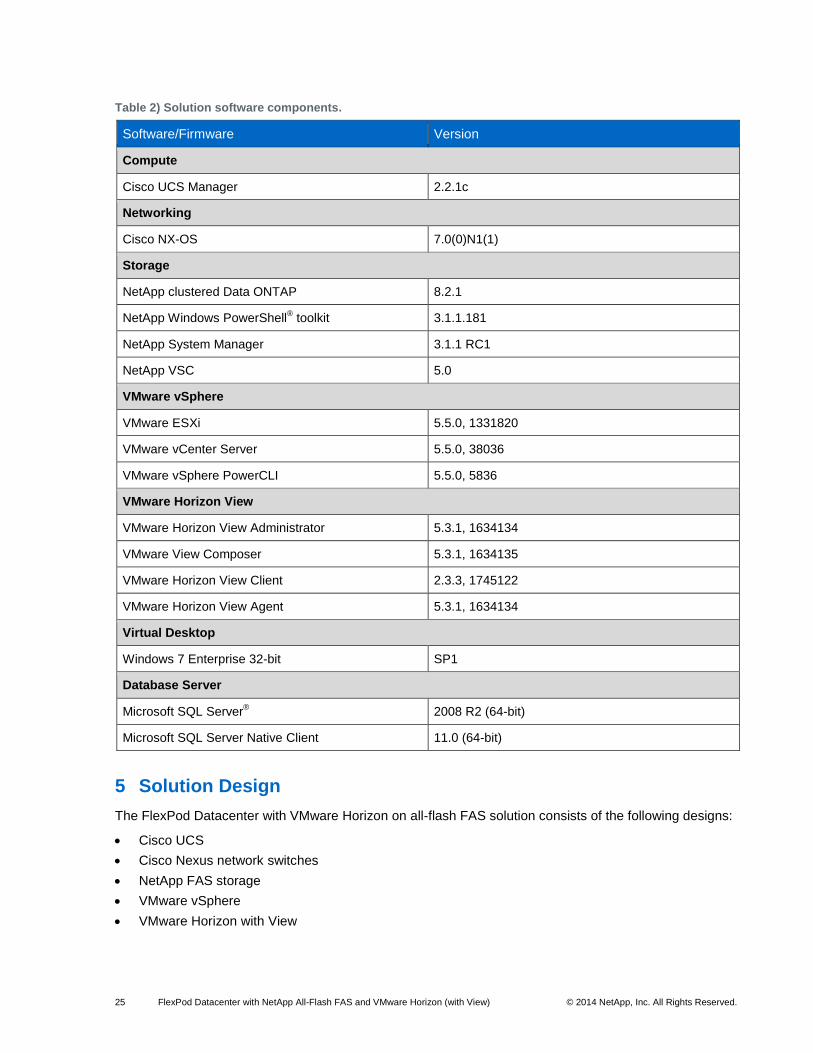
4.2 Software Components
Table 2 lists the software components used to implement the solution. The software components used in
any particular implementation of the solution may vary based on customer requirements.
25 FlexPod Datacenter with NetApp All-Flash FAS and VMware Horizon (with View) © 2014 NetApp, Inc. All Rights Reserved.
Table 2) Solution software components.
Software/Firmware Version
Compute
Cisco UCS Manager 2.2.1c
Networking
Cisco NX-OS 7.0(0)N1(1)
Storage
NetApp clustered Data ONTAP 8.2.1
NetApp Windows PowerShell® toolkit 3.1.1.181
NetApp System Manager 3.1.1 RC1
NetApp VSC 5.0
VMware vSphere
VMware ESXi 5.5.0, 1331820
VMware vCenter Server 5.5.0, 38036
VMware vSphere PowerCLI 5.5.0, 5836
VMware Horizon View
VMware Horizon View Administrator 5.3.1, 1634134
VMware View Composer 5.3.1, 1634135
VMware Horizon View Client 2.3.3, 1745122
VMware Horizon View Agent 5.3.1, 1634134
Virtual Desktop
Windows 7 Enterprise 32-bit SP1
Database Server
Microsoft SQL Server® 2008 R2 (64-bit)
Microsoft SQL Server Native Client 11.0 (64-bit)
5 Solution Design
The FlexPod Datacenter with VMware Horizon on all-flash FAS solution consists of the following designs:
Cisco UCS
Cisco Nexus network switches
NetApp FAS storage
VMware vSphere
VMware Horizon with View

26 FlexPod Datacenter with NetApp All-Flash FAS and VMware Horizon (with View) © 2014 NetApp, Inc. All Rights Reserved.
5.1 Cisco UCS Design
The FlexPod design simultaneously supports both B-Series and C-Series deployments. This section of
the document discusses only the integration and design of B-Series deployments into FlexPod.
Cisco UCS—B-Series Server Design
The Cisco UCS supports the virtual server environment by providing a robust, highly available, and
extremely manageable compute resource. As Figure 9 illustrates, the components of the Cisco UCS
system offer physical redundancy and a set of logical structures to deliver a very resilient FlexPod
compute domain. In this verification effort, multiple Cisco UCS B-Series servers’ service profiles are SAN
booted through FCoE as VMware ESXi nodes. The ESXi nodes consisted of Cisco UCS B200-M3 blades
with Cisco 1240 VIC adapters. These nodes were allocated to a VMware DRS and HA-enabled cluster
supporting infrastructure services such as vSphere Virtual Center, Microsoft Active Directory® (AD), and
database services.
Figure 9) FlexPod distinct uplink design: Cisco UCS B-Series and Cisco Nexus 5500 focus.
As illustrated in Figure 9, the Cisco 1240 VIC presents four virtual PCIe devices to the ESXi node, two
virtual 10Gb Ethernet NICs (vNICs), and two virtual host bus adapters (vHBAs). The vSphere
environment identifies these as VMNICs and VMHBAs, respectively. The ESXi OS is unaware that these
are virtual adapters. The result is a dual-homed ESXi node to the remaining network from a LAN and
SAN perspective.
27 FlexPod Datacenter with NetApp All-Flash FAS and VMware Horizon (with View) © 2014 NetApp, Inc. All Rights Reserved.
In FlexPod, the vHBA adapters use FCoE for transport across the fabric. The ESXi node has connections
to two independent fabrics, Fabrics A and B. The Cisco UCS domain constructs distinct virtual circuits (in
this example, VC 737 and VC 769) to maintain fabric separation and integrity.
FlexPod allows organizations to adjust the individual components of the system to meet their particular
scale or performance requirements. One key design decision in the Cisco UCS domain is the selection of
I/O components. There are numerous combinations of I/O adapter, Cisco UCS Extenders I/O module
(IOM), and Cisco UCS Fabric Interconnect available, so it is important to understand the impact of these
selections on the overall flexibility, scalability, and resiliency of the fabric.
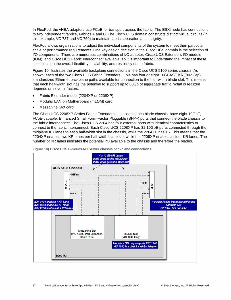
Figure 10 illustrates the available backplane connections in the Cisco UCS 5100 series chassis. As
shown, each of the two Cisco UCS Fabric Extenders IOMs has four or eight 10GBASE KR (802.3ap)
standardized Ethernet backplane paths available for connection to the half-width blade slot. This means
that each half-width slot has the potential to support up to 80Gb of aggregate traffic. What is realized
depends on several factors:
Fabric Extender model (2204XP or 2208XP)
Modular LAN on Motherboard (mLOM) card
Mezzanine Slot card
The Cisco UCS 2208XP Series Fabric Extenders, installed in each blade chassis, have eight 10GbE,
FCoE-capable, Enhanced Small Form-Factor Pluggable (SFP+) ports that connect the blade chassis to
the fabric interconnect. The Cisco UCS 2204 has four external ports with identical characteristics to
connect to the fabric interconnect. Each Cisco UCS 2208XP has 32 10GbE ports connected through the
midplane KR lanes to each half-width slot in the chassis, while the 2204XP has 16. This means that the
2204XP enables two KR lanes per half-width blade slot while the 2208XP enables all four KR lanes. The
number of KR lanes indicates the potential I/O available to the chassis and therefore the blades.
Figure 10) Cisco UCS B-Series M3 Server chassis backplane connections.
28 FlexPod Datacenter with NetApp All-Flash FAS and VMware Horizon (with View) © 2014 NetApp, Inc. All Rights Reserved.
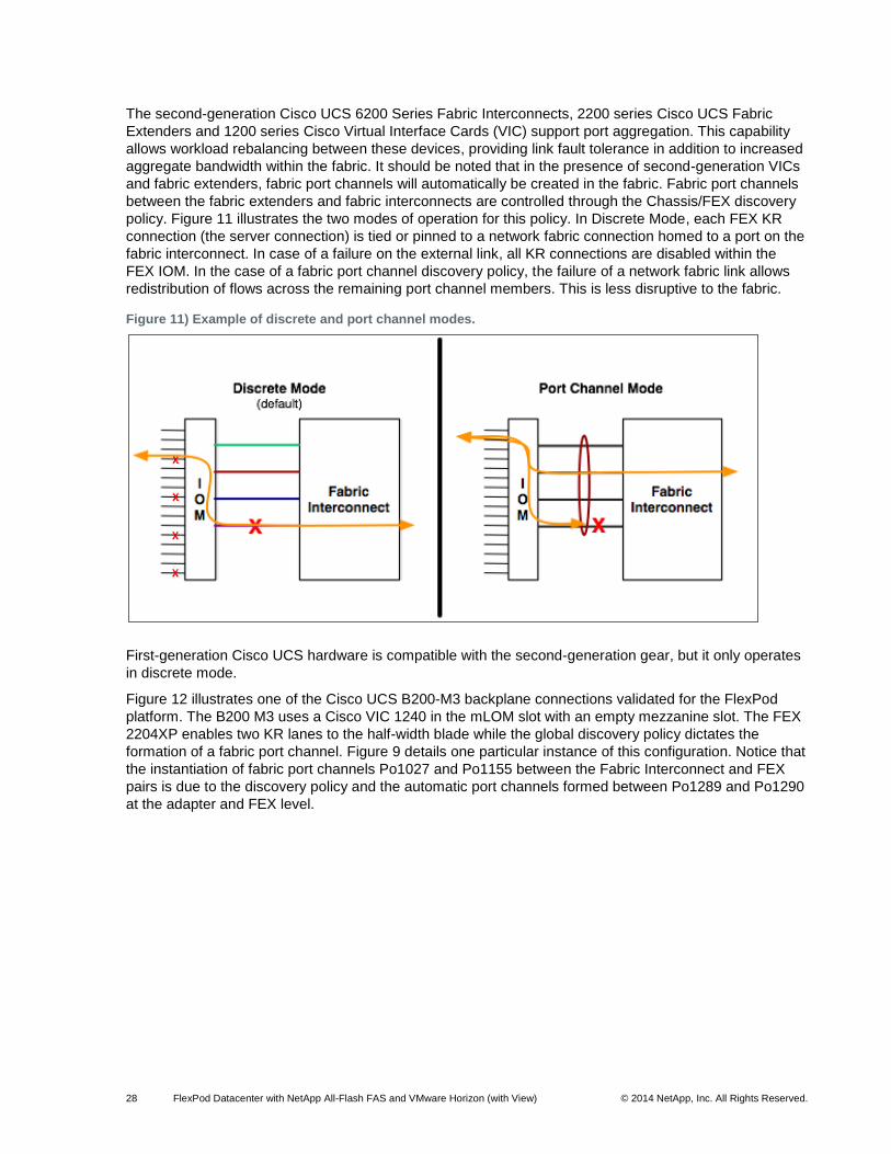
The second-generation Cisco UCS 6200 Series Fabric Interconnects, 2200 series Cisco UCS Fabric
Extenders and 1200 series Cisco Virtual Interface Cards (VIC) support port aggregation. This capability
allows workload rebalancing between these devices, providing link fault tolerance in addition to increased
aggregate bandwidth within the fabric. It should be noted that in the presence of second-generation VICs
and fabric extenders, fabric port channels will automatically be created in the fabric. Fabric port channels
between the fabric extenders and fabric interconnects are controlled through the Chassis/FEX discovery
policy. Figure 11 illustrates the two modes of operation for this policy. In Discrete Mode, each FEX KR
connection (the server connection) is tied or pinned to a network fabric connection homed to a port on the
fabric interconnect. In case of a failure on the external link, all KR connections are disabled within the
FEX IOM. In the case of a fabric port channel discovery policy, the failure of a network fabric link allows
redistribution of flows across the remaining port channel members. This is less disruptive to the fabric.
Figure 11) Example of discrete and port channel modes.
First-generation Cisco UCS hardware is compatible with the second-generation gear, but it only operates
in discrete mode.
Figure 12 illustrates one of the Cisco UCS B200-M3 backplane connections validated for the FlexPod
platform. The B200 M3 uses a Cisco VIC 1240 in the mLOM slot with an empty mezzanine slot. The FEX
2204XP enables two KR lanes to the half-width blade while the global discovery policy dictates the
formation of a fabric port channel. Figure 9 details one particular instance of this configuration. Notice that
the instantiation of fabric port channels Po1027 and Po1155 between the Fabric Interconnect and FEX
pairs is due to the discovery policy and the automatic port channels formed between Po1289 and Po1290
at the adapter and FEX level.
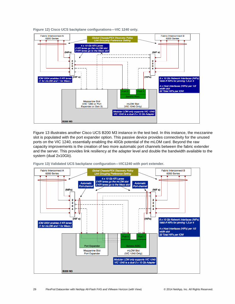
29 FlexPod Datacenter with NetApp All-Flash FAS and VMware Horizon (with View) © 2014 NetApp, Inc. All Rights Reserved.
Figure 12) Cisco UCS backplane configurations—VIC 1240 only.
Figure 13 illustrates another Cisco UCS B200 M3 instance in the test bed. In this instance, the mezzanine
slot is populated with the port expander option. This passive device provides connectivity for the unused
ports on the VIC 1240, essentially enabling the 40Gb potential of the mLOM card. Beyond the raw
capacity improvements is the creation of two more automatic port channels between the fabric extender
and the server. This provides link resiliency at the adapter level and double the bandwidth available to the
system (dual 2x10Gb).
Figure 13) Validated UCS backplane configuration—VIC1240 with port extender.
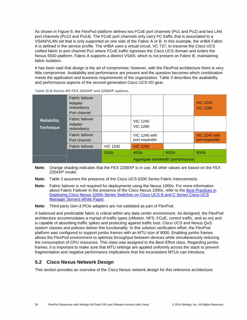
30 FlexPod Datacenter with NetApp All-Flash FAS and VMware Horizon (with View) © 2014 NetApp, Inc. All Rights Reserved.
As shown in Figure 9, the FlexPod platform defines two FCoE port channels (Po1 and Po2) and two LAN
port channels (Po13 and Po14). The FCoE port channels only carry FC traffic that is associated to a
VSAN/VLAN set that is only supported on one side of the Fabric A or B. In this example, the vHBA Fabric
A is defined in the service profile. The vHBA uses a virtual circuit, VC 737, to traverse the Cisco UCS
unified fabric to port channel Po1 where FCoE traffic egresses the Cisco UCS domain and enters the
Nexus 5500 platform. Fabric A supports a distinct VSAN, which is not present on Fabric B, maintaining
fabric isolation.
It has been said that design is the art of compromise; however, with the FlexPod architecture there is very
little compromise. Availability and performance are present and the question becomes which combination
meets the application and business requirements of the organization. Table 3 describes the availability
and performance aspects of the second-generation Cisco UCS I/O gear.
Table 3) B-Series M3 FEX 2204XP and 2208XP options.
Reliability
Technique
Fabric failover
Adapter redundancy
Port channel
VIC 1240
VIC 1280
Fabric failover
Adapter redundancy
VIC 1240
VIC 1280
Fabric failover
Port channel VIC 1240 with
port expander
VIC 1240 with port expander
Fabric failover VIC 1240 VIC 1240
20Gb 40Gb 60Gb 80Gb
Aggregate bandwidth (performance)
Note: Orange shading indicates that the FEX 2208XP is in use. All other values are based on the FEX 2204XP model.
Note: Table 3 assumes the presence of the Cisco UCS 6200 Series Fabric Interconnects.
Note: Fabric failover is not required for deployments using the Nexus 1000v. For more information about Fabric Failover in the presence of the Cisco Nexus 1000v, refer to the Best Practices in Deploying Cisco Nexus 1000v Series Switches on Cisco UCS B and C Series Cisco UCS Manager Servers White Paper.
Note: Third-party Gen-3 PCIe adapters are not validated as part of FlexPod.
A balanced and predictable fabric is critical within any data center environment. As designed, the FlexPod
architecture accommodates a myriad of traffic types (vMotion, NFS, FCoE, control traffic, and so on) and
is capable of absorbing traffic spikes and protecting against traffic loss. Cisco UCS and Nexus QoS
system classes and policies deliver this functionality. In this solution verification effort, the FlexPod
platform was configured to support jumbo frames with an MTU size of 9000. Enabling jumbo frames
allows the FlexPod environment to optimize throughput between devices while simultaneously reducing
the consumption of CPU resources. This class was assigned to the Best-Effort class. Regarding jumbo
frames, it is important to make sure that MTU settings are applied uniformly across the stack to prevent
fragmentation and negative performance implications that the inconsistent MTUs can introduce.
5.2 Cisco Nexus Network Design
This section provides an overview of the Cisco Nexus network design for this reference architecture.
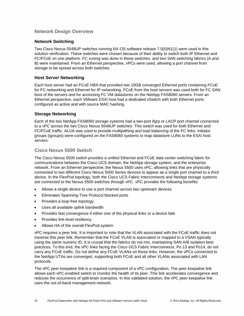
31 FlexPod Datacenter with NetApp All-Flash FAS and VMware Horizon (with View) © 2014 NetApp, Inc. All Rights Reserved.
Network Design Overview
Network Switching
Two Cisco Nexus 5548UP switches running NX-OS software release 7.0(0)N1(1) were used in this
solution verification. These switches were chosen because of their ability to switch both IP Ethernet and
FC/FCoE on one platform. FC zoning was done in these switches, and two SAN switching fabrics (A and
B) were maintained. From an Ethernet perspective, vPCs were used, allowing a port channel from
storage to be spread across both switches.
Host Server Networking
Each host server had an FCoE HBA that provided two 10GB converged Ethernet ports containing FCoE
for FC networking and Ethernet for IP networking. FCoE from the host servers was used both for FC SAN
boot of the servers and for accessing FC VM datastores on the NetApp FAS8060 servers. From an
Ethernet perspective, each VMware ESXi host had a dedicated vSwitch with both Ethernet ports
configured as active and with source MAC hashing.
Storage Networking
Each of the two NetApp FAS8060 storage systems had a two-port ifgrp or LACP port channel connected
to a vPC across the two Cisco Nexus 5548UP switches. This switch was used for both Ethernet and
FC/FCoE traffic. ALUA was used to provide multipathing and load balancing of the FC links. Initiator
groups (igroups) were configured on the FAS8060 systems to map datastore LUNs to the ESXi host
servers.
Cisco Nexus 5500 Switch
The Cisco Nexus 5500 switch provides a unified Ethernet and FCoE data center switching fabric for
communications between the Cisco UCS domain, the NetApp storage system, and the enterprise
network. From an Ethernet perspective, the Nexus 5500 uses vPC, allowing links that are physically
connected to two different Cisco Nexus 5000 Series devices to appear as a single port channel to a third
device. In the FlexPod topology, both the Cisco UCS Fabric Interconnects and NetApp storage systems
are connected to the Nexus 5500 switches through vPC. vPC provides the following benefits:
Allows a single device to use a port channel across two upstream devices
Eliminates Spanning-Tree Protocol blocked ports
Provides a loop-free topology
Uses all available uplink bandwidth
Provides fast convergence if either one of the physical links or a device fails
Provides link-level resiliency
Allows HA of the overall FlexPod system
vPC requires a peer link. It is important to note that the VLAN associated with the FCoE traffic does not
traverse this peer link. Remember that the FCoE VLAN is associated or mapped to a VSAN typically
using the same numeric ID. It is crucial that the fabrics do not mix, maintaining SAN A/B isolation best
practices. To this end, the vPC links facing the Cisco UCS Fabric Interconnects, Po 13 and Po14, do not
carry any FCoE traffic. Do not define any FCoE VLANs on these links. However, the vPCs connected to
the NetApp UTAs are converged, supporting both FCoE and all other VLANs associated with LAN
protocols.
The vPC peer keepalive link is a required component of a vPC configuration. The peer keepalive link
allows each vPC-enabled switch to monitor the health of its peer. This link accelerates convergence and
reduces the occurrence of split-brain scenarios. In this validated solution, the vPC peer keepalive link
uses the out-of-band management network.
32 FlexPod Datacenter with NetApp All-Flash FAS and VMware Horizon (with View) © 2014 NetApp, Inc. All Rights Reserved.
Each Nexus 5500 defines a port channel dedicated to FCoE and connected to the Cisco UCS Fabric
Interconnects, in this instance Po15 and Po16. Each discrete port channel supports a single VLAN
associated with Fabric A or Fabric B. A virtual Fibre Channel (VFC) interface is then bound to the logical
port channel interface. This same construct is applied to the vPCs facing the NetApp storage controllers,
in this example, VFC11 and VFC12. This offers universal accessibility of the fabric to each NetApp
storage node in case of failures. To maintain SAN A/B isolation, VFC 11 and 12 are associated to a
different VLAN/VSAN pairing, meaning that the vPCs facing the NetApp storage systems support all LAN
and FCoE traffic but have unique FCoE VLANs defined on each Nexus switch.
Note: It is a NetApp best practice to name the VFC for the port channel on which it resides. For example, VFC15 is on port channel 15.
The Cisco Nexus 5500 in the FlexPod design provides FC services to the Cisco UCS and NetApp FAS
platforms. Internally, the Cisco Nexus 5500 platforms must be configured to support FC zoning to enforce
the access policy between Cisco UCS–based initiators and FAS-based targets. Without a zoning
configuration, there is no communication between initiators and targets.
FlexPod is a converged infrastructure platform. This convergence is possible because of the support of
Ethernet enhancements across the integrated compute stack in regard to bandwidth allocation and flow
control based on traffic classification. As such it is important to implement the following QoS techniques to
provide QoS in the FlexPod configuration:
Priority Flow Control (PFC) 802.1Qbb. Lossless Ethernet using a PAUSE on a per class of service (CoS) basis
Enhanced Transmission Selection (ETS) 802.1Qaz. Traffic protection through bandwidth management
Data Center Bridging Capability Exchange (DCBX). Negotiates Ethernet functionality between devices (PFC, ETS, and CoS values)
The Cisco Nexus 5500 supports these capabilities through QoS policies. QoS is enabled by default and
managed using the Cisco Modular QoS CLI (MQC), providing class-based traffic control. The Cisco
Nexus system instantiates basic QoS classes for Ethernet traffic and a system FCoE class (class-fcoe)
when the FCoE feature is enabled. It is important to align the QoS setting (CoS, MTU) within the Cisco
Nexus 5500, the Cisco UCS Fabric Interconnects, and the Cisco Nexus 1000v configurations. Realize
that DCBX signaling can impact the NetApp controller. Make sure to allocate the proper bandwidth based
on the site’s application needs to the appropriate CoS classes and keep MTU settings consistent in the
environment to avoid fragmentation issues and improve performance.
The following best practices were used in the verification of the FlexPod architecture:
Cisco Nexus 5500 features enabled:
FCoE, which uses the PFC (802.1Qbb), ETS (802.1Qaz), and DCBX (802.1Qaz) to provide a lossless fabric
NPIV, which allows the network fabric port (N-Port) to be virtualized and support multiple FC initiators on a single physical port
LACP, part of 802.3ad
Cisco vPC for link and device resiliency
Link Layer Discovery Protocol (LLDP), which allows the Cisco Nexus 5000 to share and discover DCBX features and capabilities between neighboring FCoE-capable devices
Cisco Discovery Protocol (CDP) for infrastructure visibility and troubleshooting
vPC considerations:
A unique domain ID must be defined
The priority of the intended vPC primary switch must be set lower than the secondary (default priority is 32768)
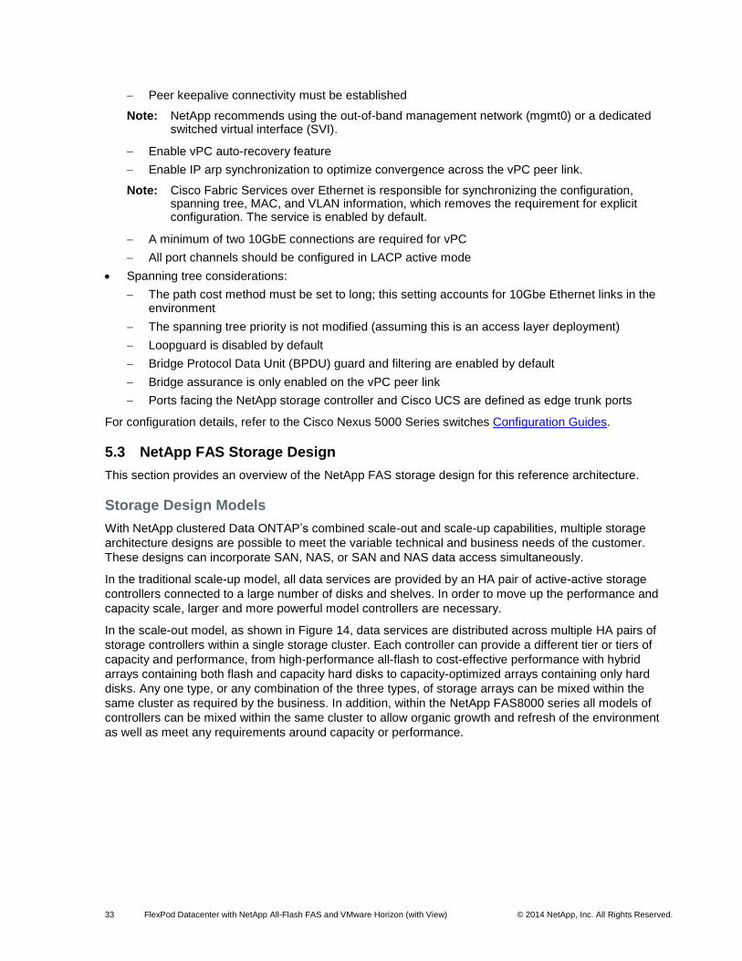
33 FlexPod Datacenter with NetApp All-Flash FAS and VMware Horizon (with View) © 2014 NetApp, Inc. All Rights Reserved.
Peer keepalive connectivity must be established
Note: NetApp recommends using the out-of-band management network (mgmt0) or a dedicated switched virtual interface (SVI).
Enable vPC auto-recovery feature
Enable IP arp synchronization to optimize convergence across the vPC peer link.
Note: Cisco Fabric Services over Ethernet is responsible for synchronizing the configuration, spanning tree, MAC, and VLAN information, which removes the requirement for explicit configuration. The service is enabled by default.
A minimum of two 10GbE connections are required for vPC
All port channels should be configured in LACP active mode
Spanning tree considerations:
The path cost method must be set to long; this setting accounts for 10Gbe Ethernet links in the environment
The spanning tree priority is not modified (assuming this is an access layer deployment)
Loopguard is disabled by default
Bridge Protocol Data Unit (BPDU) guard and filtering are enabled by default
Bridge assurance is only enabled on the vPC peer link
Ports facing the NetApp storage controller and Cisco UCS are defined as edge trunk ports
For configuration details, refer to the Cisco Nexus 5000 Series switches Configuration Guides.
5.3 NetApp FAS Storage Design
This section provides an overview of the NetApp FAS storage design for this reference architecture.
Storage Design Models
With NetApp clustered Data ONTAP’s combined scale-out and scale-up capabilities, multiple storage
architecture designs are possible to meet the variable technical and business needs of the customer.
These designs can incorporate SAN, NAS, or SAN and NAS data access simultaneously.
In the traditional scale-up model, all data services are provided by an HA pair of active-active storage
controllers connected to a large number of disks and shelves. In order to move up the performance and
capacity scale, larger and more powerful model controllers are necessary.
In the scale-out model, as shown in Figure 14, data services are distributed across multiple HA pairs of
storage controllers within a single storage cluster. Each controller can provide a different tier or tiers of
capacity and performance, from high-performance all-flash to cost-effective performance with hybrid
arrays containing both flash and capacity hard disks to capacity-optimized arrays containing only hard
disks. Any one type, or any combination of the three types, of storage arrays can be mixed within the
same cluster as required by the business. In addition, within the NetApp FAS8000 series all models of
controllers can be mixed within the same cluster to allow organic growth and refresh of the environment
as well as meet any requirements around capacity or performance.
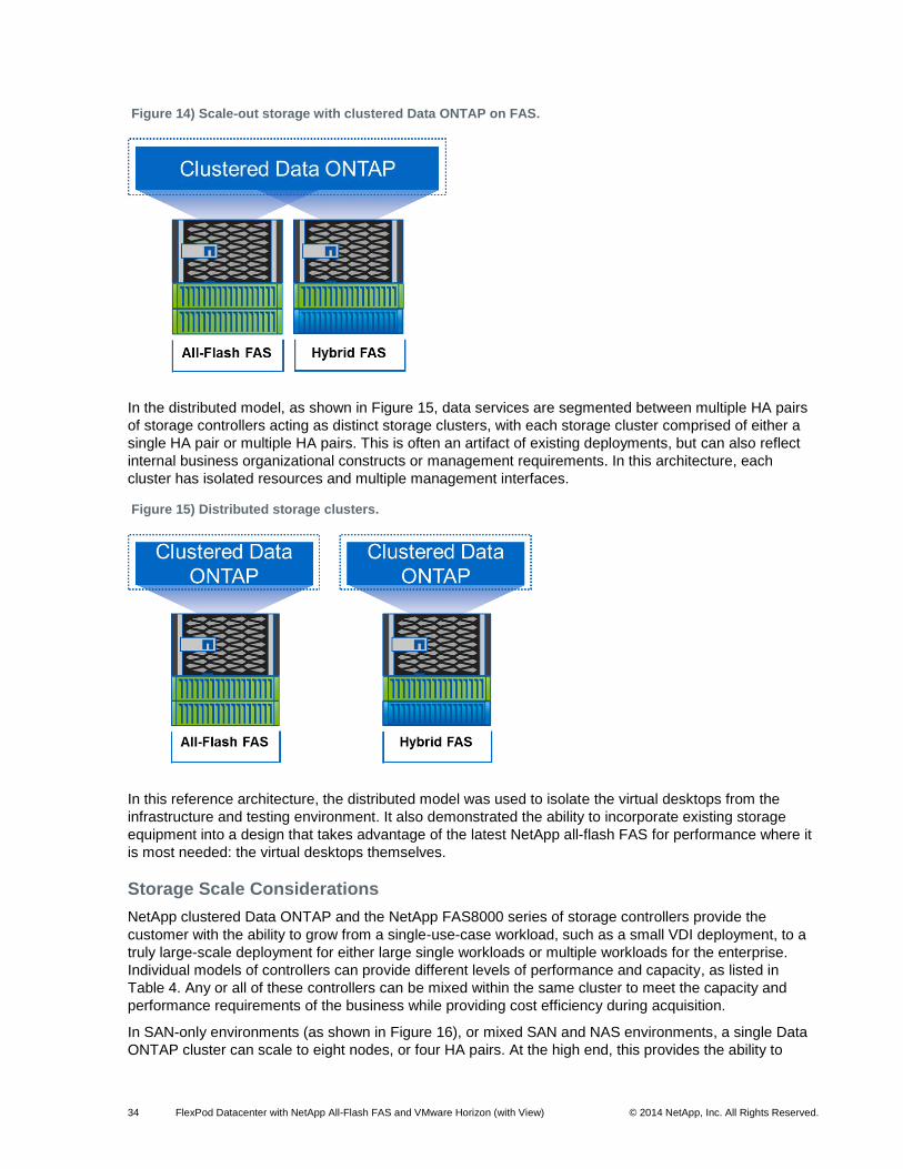
34 FlexPod Datacenter with NetApp All-Flash FAS and VMware Horizon (with View) © 2014 NetApp, Inc. All Rights Reserved.
Figure 14) Scale-out storage with clustered Data ONTAP on FAS.
In the distributed model, as shown in Figure 15, data services are segmented between multiple HA pairs
of storage controllers acting as distinct storage clusters, with each storage cluster comprised of either a
single HA pair or multiple HA pairs. This is often an artifact of existing deployments, but can also reflect
internal business organizational constructs or management requirements. In this architecture, each
cluster has isolated resources and multiple management interfaces.
Figure 15) Distributed storage clusters.
In this reference architecture, the distributed model was used to isolate the virtual desktops from the
infrastructure and testing environment. It also demonstrated the ability to incorporate existing storage
equipment into a design that takes advantage of the latest NetApp all-flash FAS for performance where it
is most needed: the virtual desktops themselves.
Storage Scale Considerations
NetApp clustered Data ONTAP and the NetApp FAS8000 series of storage controllers provide the
customer with the ability to grow from a single-use-case workload, such as a small VDI deployment, to a
truly large-scale deployment for either large single workloads or multiple workloads for the enterprise.
Individual models of controllers can provide different levels of performance and capacity, as listed in
Table 4. Any or all of these controllers can be mixed within the same cluster to meet the capacity and
performance requirements of the business while providing cost efficiency during acquisition.
In SAN-only environments (as shown in Figure 16), or mixed SAN and NAS environments, a single Data
ONTAP cluster can scale to eight nodes, or four HA pairs. At the high end, this provides the ability to
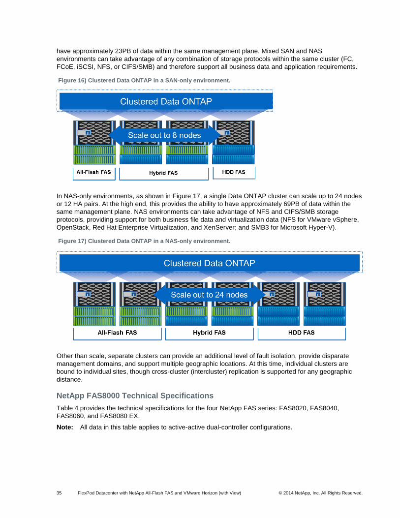
35 FlexPod Datacenter with NetApp All-Flash FAS and VMware Horizon (with View) © 2014 NetApp, Inc. All Rights Reserved.
have approximately 23PB of data within the same management plane. Mixed SAN and NAS
environments can take advantage of any combination of storage protocols within the same cluster (FC,
FCoE, iSCSI, NFS, or CIFS/SMB) and therefore support all business data and application requirements.
Figure 16) Clustered Data ONTAP in a SAN-only environment.
In NAS-only environments, as shown in Figure 17, a single Data ONTAP cluster can scale up to 24 nodes
or 12 HA pairs. At the high end, this provides the ability to have approximately 69PB of data within the
same management plane. NAS environments can take advantage of NFS and CIFS/SMB storage
protocols, providing support for both business file data and virtualization data (NFS for VMware vSphere,
OpenStack, Red Hat Enterprise Virtualization, and XenServer; and SMB3 for Microsoft Hyper-V).
Figure 17) Clustered Data ONTAP in a NAS-only environment.
Other than scale, separate clusters can provide an additional level of fault isolation, provide disparate
management domains, and support multiple geographic locations. At this time, individual clusters are
bound to individual sites, though cross-cluster (intercluster) replication is supported for any geographic
distance.
NetApp FAS8000 Technical Specifications
Table 4 provides the technical specifications for the four NetApp FAS series: FAS8020, FAS8040,
FAS8060, and FAS8080 EX.
Note: All data in this table applies to active-active dual-controller configurations.
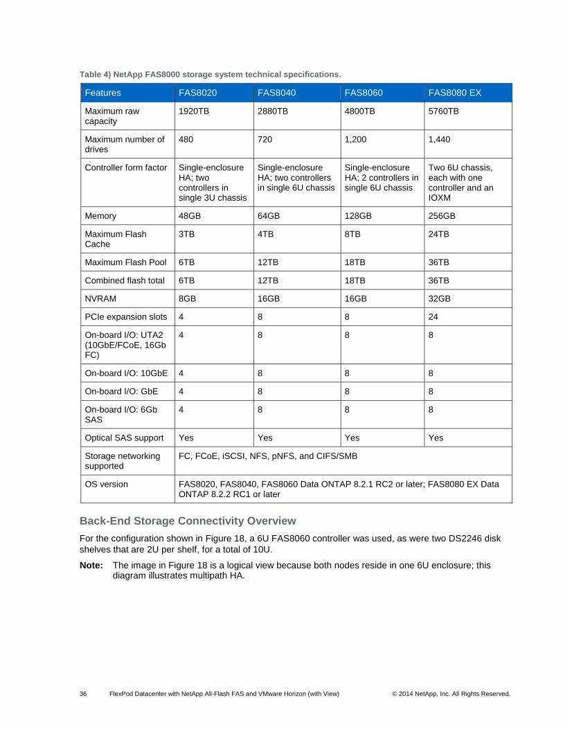
36 FlexPod Datacenter with NetApp All-Flash FAS and VMware Horizon (with View) © 2014 NetApp, Inc. All Rights Reserved.
Table 4) NetApp FAS8000 storage system technical specifications.
Features FAS8020 FAS8040 FAS8060 FAS8080 EX
Maximum raw capacity
1920TB 2880TB 4800TB 5760TB
Maximum number of drives
480 720 1,200 1,440
Controller form factor Single-enclosure HA; two controllers in single 3U chassis
Single-enclosure HA; two controllers in single 6U chassis
Single-enclosure HA; 2 controllers in single 6U chassis
Two 6U chassis, each with one controller and an IOXM
Memory 48GB 64GB 128GB 256GB
Maximum Flash Cache
3TB 4TB 8TB 24TB
Maximum Flash Pool 6TB 12TB 18TB 36TB
Combined flash total 6TB 12TB 18TB 36TB
NVRAM 8GB 16GB 16GB 32GB
PCIe expansion slots 4 8 8 24
On-board I/O: UTA2 (10GbE/FCoE, 16Gb FC)
4 8 8 8
On-board I/O: 10GbE 4 8 8 8
On-board I/O: GbE 4 8 8 8
On-board I/O: 6Gb SAS
4 8 8 8
Optical SAS support Yes Yes Yes Yes
Storage networking supported
FC, FCoE, iSCSI, NFS, pNFS, and CIFS/SMB
OS version FAS8020, FAS8040, FAS8060 Data ONTAP 8.2.1 RC2 or later; FAS8080 EX Data ONTAP 8.2.2 RC1 or later
Back-End Storage Connectivity Overview
For the configuration shown in Figure 18, a 6U FAS8060 controller was used, as were two DS2246 disk
shelves that are 2U per shelf, for a total of 10U.
Note: The image in Figure 18 is a logical view because both nodes reside in one 6U enclosure; this diagram illustrates multipath HA.
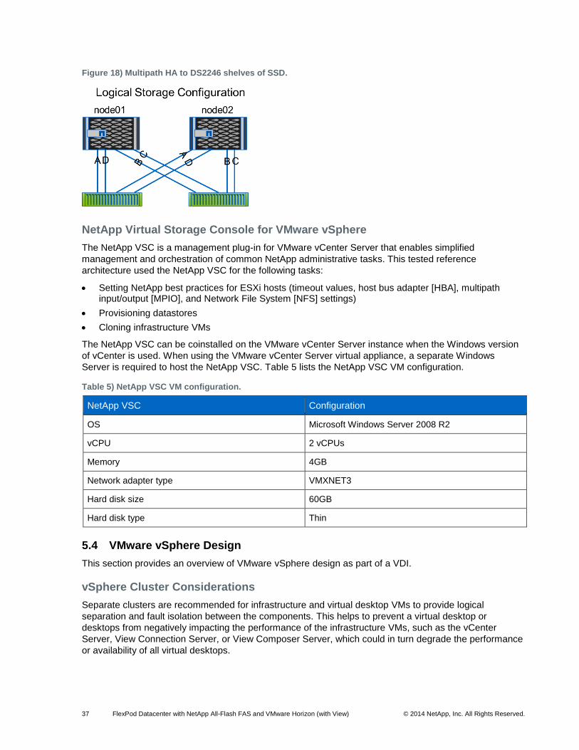
37 FlexPod Datacenter with NetApp All-Flash FAS and VMware Horizon (with View) © 2014 NetApp, Inc. All Rights Reserved.
Figure 18) Multipath HA to DS2246 shelves of SSD.
NetApp Virtual Storage Console for VMware vSphere
The NetApp VSC is a management plug-in for VMware vCenter Server that enables simplified
management and orchestration of common NetApp administrative tasks. This tested reference
architecture used the NetApp VSC for the following tasks:
Setting NetApp best practices for ESXi hosts (timeout values, host bus adapter [HBA], multipath input/output [MPIO], and Network File System [NFS] settings)
Provisioning datastores
Cloning infrastructure VMs
The NetApp VSC can be coinstalled on the VMware vCenter Server instance when the Windows version
of vCenter is used. When using the VMware vCenter Server virtual appliance, a separate Windows
Server is required to host the NetApp VSC. Table 5 lists the NetApp VSC VM configuration.
Table 5) NetApp VSC VM configuration.
NetApp VSC Configuration
OS Microsoft Windows Server 2008 R2
vCPU 2 vCPUs
Memory 4GB
Network adapter type VMXNET3
Hard disk size 60GB
Hard disk type Thin
5.4 VMware vSphere Design
This section provides an overview of VMware vSphere design as part of a VDI.
vSphere Cluster Considerations
Separate clusters are recommended for infrastructure and virtual desktop VMs to provide logical
separation and fault isolation between the components. This helps to prevent a virtual desktop or
desktops from negatively impacting the performance of the infrastructure VMs, such as the vCenter
Server, View Connection Server, or View Composer Server, which could in turn degrade the performance
or availability of all virtual desktops.
38 FlexPod Datacenter with NetApp All-Flash FAS and VMware Horizon (with View) © 2014 NetApp, Inc. All Rights Reserved.
vSphere HA should be enabled so that host failures result in only a short outage before VMs are
automatically brought back online. Host Monitoring and Admission Control should be enabled so that at
least one host failure or maintenance operation can be tolerated while still providing sufficient resources
to run the entire workload of the cluster. Additional capacity may be reserved to provide greater
headroom for concurrent host failures or maintenance.
vSphere Dynamic Resource Scheduler (DRS) is also recommended to automatically balance CPU and
memory workloads across the cluster members. This is very important in a virtual desktop environment
where the number of VMs and variability of workload is typically higher than in virtual server
environments. DRS provides automated remediation of host resource contention and decreases the
likelihood of a “bully” desktop negatively impacting other desktops on the same host.
As previously described, VMware vSphere clusters can scale up to 32 nodes within a single cluster. This
limit is unrelated to the number of physical CPUs or cores within any or all of the nodes. If larger
operational scale is a primary concern, using larger hosts, such as with four or more processors and/or
commensurately larger amounts of memory, allows greater density within a single vSphere cluster.
Scaling up hosts also provides benefits around great effectiveness of vSphere memory oversubscription
as a result of Transparent Page Sharing, as well as the efficiency of host-based caching technologies
such as vSphere Flash Read Cache.
It should be noted that as a host scales up, failure domains scale equally: Failure of a two-CPU server
can result in the failure of 100–150 VMs, whereas a four-CPU server can impact twice as many VMs.
Although failures are rare, they must still be taken into account when designing the infrastructure. Fewer
hosts per cluster also provide vSphere DRS with fewer options to optimally balance the virtual desktop
workload, and therefore increase the likelihood of host resource contention.
In addition, some maintenance operations can also be impacted by the relative size of the host:
Evacuating a host with 200–300 VMs requires more time than evacuating one with half the amount of
workload. Maintenance operations like this can be mitigated through the appropriate configuration of
multi-NIC vMotion, among other technologies, and should be addressed in the vSphere networking
design.
The maximum number of VMs that can be registered to a single vSphere host is 512, and the maximum
number of VMs within a single vSphere cluster is 4,000. Based on these limits, the minimum number of
hosts required for 4,000 virtual desktops is nine (eight hosts to provide capacity for the VMs plus at least
one host for failover capacity), for an effective host-to-VM ratio of 1:445 during normal operations and
1:500 during a single-host-failure/maintenance event. Using the maximum number of hosts (32) for 4,000
virtual desktops provides an effective host-to-VM ratio of 1:125 during normal operations and 1:130
during a single-host-failure/maintenance event. In real-world deployments, gating factors for such ratios
are both available physical memory and CPU resources and they depend on the specific applications and
workloads used within the customer’s environment. The most typical (and at this time most cost-effective)
host-to-VM ratio is between 1:125 and 1:225 for a dual-CPU vSphere host. In general, each CPU core
can provide sufficient compute resources for 8 to 10 virtual desktop CPUs.
vSphere Networking Considerations
In this reference architecture, standard vSwitches were used for the VM connectivity, management
vmkernel, and vMotion vmkernel portgroups. VMware vSphere Enterprise Plus licensing enables other
networking options that provide additional features beyond standard virtual switches: Distributed Virtual
Switches, Cisco Nexus 1000v, or Cisco Virtual Machine Fabric Extender (VM-FEX).
VMware vSphere Distributed Virtual Switches
The VMware vSphere Distributed Switch (VDS) provides a number of benefits over traditional (or
standard) vSwitches, including centralized management of virtual networking across the entire virtual data
center and support for advanced VMware vSphere networking features. These advanced features
include:
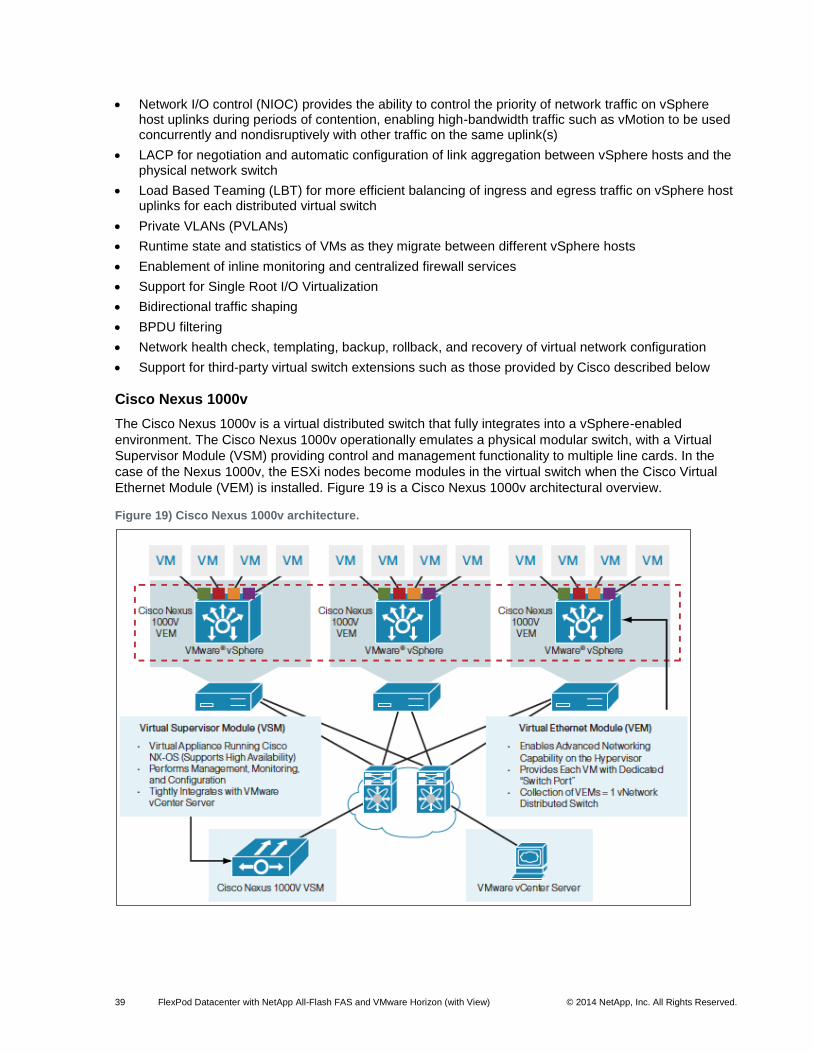
39 FlexPod Datacenter with NetApp All-Flash FAS and VMware Horizon (with View) © 2014 NetApp, Inc. All Rights Reserved.
Network I/O control (NIOC) provides the ability to control the priority of network traffic on vSphere host uplinks during periods of contention, enabling high-bandwidth traffic such as vMotion to be used concurrently and nondisruptively with other traffic on the same uplink(s)
LACP for negotiation and automatic configuration of link aggregation between vSphere hosts and the physical network switch
Load Based Teaming (LBT) for more efficient balancing of ingress and egress traffic on vSphere host uplinks for each distributed virtual switch
Private VLANs (PVLANs)
Runtime state and statistics of VMs as they migrate between different vSphere hosts
Enablement of inline monitoring and centralized firewall services
Support for Single Root I/O Virtualization
Bidirectional traffic shaping
BPDU filtering
Network health check, templating, backup, rollback, and recovery of virtual network configuration
Support for third-party virtual switch extensions such as those provided by Cisco described below
Cisco Nexus 1000v
The Cisco Nexus 1000v is a virtual distributed switch that fully integrates into a vSphere-enabled
environment. The Cisco Nexus 1000v operationally emulates a physical modular switch, with a Virtual
Supervisor Module (VSM) providing control and management functionality to multiple line cards. In the
case of the Nexus 1000v, the ESXi nodes become modules in the virtual switch when the Cisco Virtual
Ethernet Module (VEM) is installed. Figure 19 is a Cisco Nexus 1000v architectural overview.
Figure 19) Cisco Nexus 1000v architecture.
40 FlexPod Datacenter with NetApp All-Flash FAS and VMware Horizon (with View) © 2014 NetApp, Inc. All Rights Reserved.
The VEM takes configuration information from the VSM and performs Layer 2 switching and advanced
networking functions, such as:
Port channels
QoS
Security: Private VLAN, access control lists (ACLs), and port security
Monitoring: NetFlow, Switch Port Analyzer (SPAN), and Encapsulated Remote SPAN (ERSPAN)
vPath providing efficient traffic redirection to one or more chained services such as the Cisco Virtual Security Gateway and Cisco ASA 1000v
Cisco Virtual Machine Fabric Extender
Cisco VM-FEX is a technology that addresses both management and performance concerns in the data
center by unifying physical and virtual switch management. The use of Cisco’s VM-FEX collapses both
virtual and physical networking into a single infrastructure, reducing the number of network management
points and enabling consistent provisioning, configuration, and management policy within the enterprise.
This is achieved by joining the Cisco UCS Manager to the VMware vCenter management platform
through the Cisco UCS VMware plug-in. This integration point between the physical and virtual domains
of the data center allows administrators to efficiently manage both their virtual and physical network
resources. The decision to use VM-FEX is typically driven by application requirements such as
performance and the operational preferences of the IT organization.
The Cisco UCS VIC offers each VM a virtual Ethernet interface or vNIC. This vNIC provides direct access
to the Cisco UCS Fabric Interconnects and the Cisco Nexus 5500 Series switches through which
forwarding decisions can be made for each VM using a VM-FEX interface. Cisco VM-FEX technology
supports two modes of operation:
Emulated mode:
The hypervisor emulates a NIC (also referred to as a back-end emulated device) to replicate the hardware it virtualizes for the guest VM. The emulated device presents descriptors, for read and write, and interrupts to the guest VM just as a real hardware NIC device would. One such NIC device that VMware ESXi emulates is the vmxnet3 device. The guest OS in turn instantiates a device driver for the emulated NIC. All the resources of the emulated devices' host interface are mapped to the address space of the guest OS.
PCIe pass-through or VMDirectPath mode:
VIC uses PCIe standards-compliant IOMMU technology from Intel and VMware's VMDirectPath technology to implement PCIe pass-through across the hypervisor layer and eliminate the associated I/O overhead. The pass-through mode can be requested in the port profile associated with the interface using the high-performance attribute.
VMware vCenter Considerations
VMware vCenter is a critical component for a VMware Horizon with View infrastructure: All management
and maintenance operations rely on it to perform correctly and efficiently. Because of the component’s
critical nature, NetApp highly recommends that as much resilience and data protection as possible is
provided for its core components (the individual vCenter modules and the vCenter database). If vCenter
is running as a VM—whether as a Windows installation or as the vCenter Server virtual appliance —
vSphere HA provides fundamental protection, as it can for the vCenter database server, if virtualized. In
addition, starting with vCenter Server 5.5, Microsoft SQL Clustering Service (MSCS) is now a supported
configuration to provide HA for the vCenter database separately from vSphere HA, or where vCenter is a
physical server.
For more information about how to configure support for MSCS with a Windows-based vCenter Server,
refer to VMware Knowledge Base (KB) article 2059560.
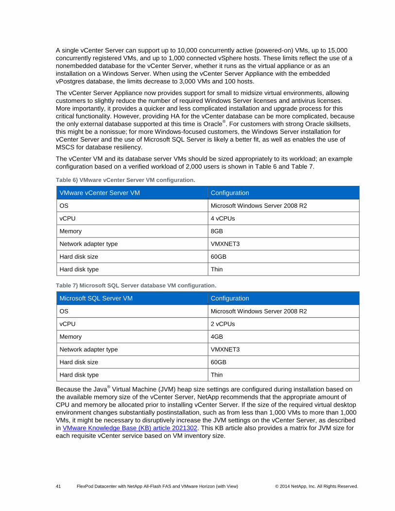
41 FlexPod Datacenter with NetApp All-Flash FAS and VMware Horizon (with View) © 2014 NetApp, Inc. All Rights Reserved.
A single vCenter Server can support up to 10,000 concurrently active (powered-on) VMs, up to 15,000
concurrently registered VMs, and up to 1,000 connected vSphere hosts. These limits reflect the use of a
nonembedded database for the vCenter Server, whether it runs as the virtual appliance or as an
installation on a Windows Server. When using the vCenter Server Appliance with the embedded
vPostgres database, the limits decrease to 3,000 VMs and 100 hosts.
The vCenter Server Appliance now provides support for small to midsize virtual environments, allowing
customers to slightly reduce the number of required Windows Server licenses and antivirus licenses.
More importantly, it provides a quicker and less complicated installation and upgrade process for this
critical functionality. However, providing HA for the vCenter database can be more complicated, because
the only external database supported at this time is Oracle®. For customers with strong Oracle skillsets,
this might be a nonissue; for more Windows-focused customers, the Windows Server installation for
vCenter Server and the use of Microsoft SQL Server is likely a better fit, as well as enables the use of
MSCS for database resiliency.
The vCenter VM and its database server VMs should be sized appropriately to its workload; an example
configuration based on a verified workload of 2,000 users is shown in Table 6 and Table 7.
Table 6) VMware vCenter Server VM configuration.
VMware vCenter Server VM Configuration
OS Microsoft Windows Server 2008 R2
vCPU 4 vCPUs
Memory 8GB
Network adapter type VMXNET3
Hard disk size 60GB
Hard disk type Thin
Table 7) Microsoft SQL Server database VM configuration.
Microsoft SQL Server VM Configuration
OS Microsoft Windows Server 2008 R2
vCPU 2 vCPUs
Memory 4GB
Network adapter type VMXNET3
Hard disk size 60GB
Hard disk type Thin
Because the Java® Virtual Machine (JVM) heap size settings are configured during installation based on
the available memory size of the vCenter Server, NetApp recommends that the appropriate amount of
CPU and memory be allocated prior to installing vCenter Server. If the size of the required virtual desktop
environment changes substantially postinstallation, such as from less than 1,000 VMs to more than 1,000
VMs, it might be necessary to disruptively increase the JVM settings on the vCenter Server, as described
in VMware Knowledge Base (KB) article 2021302. This KB article also provides a matrix for JVM size for
each requisite vCenter service based on VM inventory size.
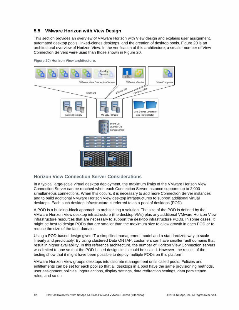
42 FlexPod Datacenter with NetApp All-Flash FAS and VMware Horizon (with View) © 2014 NetApp, Inc. All Rights Reserved.
5.5 VMware Horizon with View Design
This section provides an overview of VMware Horizon with View design and explains user assignment,
automated desktop pools, linked-clones desktops, and the creation of desktop pools. Figure 20 is an
architectural overview of Horizon View. In the verification of this architecture, a smaller number of View
Connection Servers were used than those shown in Figure 20.
Figure 20) Horizon View architecture.
Horizon View Connection Server Considerations
In a typical large-scale virtual desktop deployment, the maximum limits of the VMware Horizon View
Connection Server can be reached when each Connection Server instance supports up to 2,000
simultaneous connections. When this occurs, it is necessary to add more Connection Server instances
and to build additional VMware Horizon View desktop infrastructures to support additional virtual
desktops. Each such desktop infrastructure is referred to as a pool of desktops (POD).
A POD is a building-block approach to architecting a solution. The size of the POD is defined by the
VMware Horizon View desktop infrastructure (the desktop VMs) plus any additional VMware Horizon View
infrastructure resources that are necessary to support the desktop infrastructure PODs. In some cases, it
might be best to design PODs that are smaller than the maximum size to allow growth in each POD or to
reduce the size of the fault domain.
Using a POD-based design gives IT a simplified management model and a standardized way to scale
linearly and predictably. By using clustered Data ONTAP, customers can have smaller fault domains that
result in higher availability. In this reference architecture, the number of Horizon View Connection servers
was limited to one so that the POD-based design limits could be scaled. However, the results of the
testing show that it might have been possible to deploy multiple PODs on this platform.
VMware Horizon View groups desktops into discrete management units called pools. Policies and
entitlements can be set for each pool so that all desktops in a pool have the same provisioning methods,
user assignment policies, logout actions, display settings, data redirection settings, data persistence
rules, and so on.
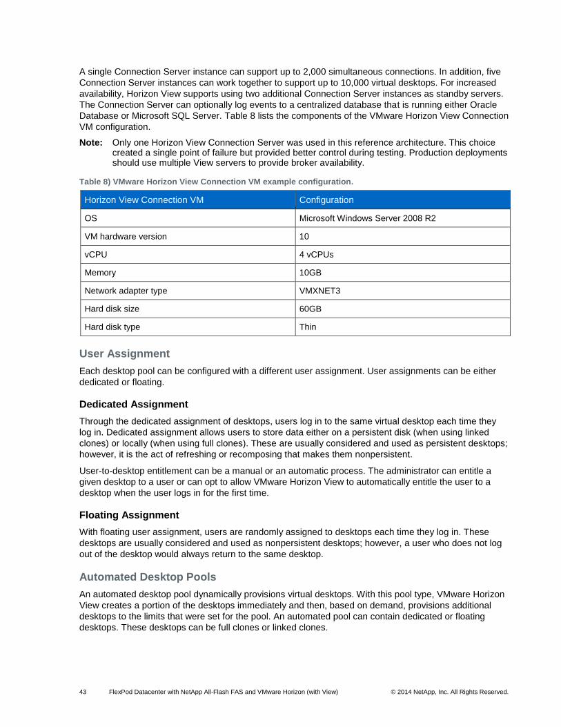
43 FlexPod Datacenter with NetApp All-Flash FAS and VMware Horizon (with View) © 2014 NetApp, Inc. All Rights Reserved.
A single Connection Server instance can support up to 2,000 simultaneous connections. In addition, five
Connection Server instances can work together to support up to 10,000 virtual desktops. For increased
availability, Horizon View supports using two additional Connection Server instances as standby servers.
The Connection Server can optionally log events to a centralized database that is running either Oracle
Database or Microsoft SQL Server. Table 8 lists the components of the VMware Horizon View Connection
VM configuration.
Note: Only one Horizon View Connection Server was used in this reference architecture. This choice created a single point of failure but provided better control during testing. Production deployments should use multiple View servers to provide broker availability.
Table 8) VMware Horizon View Connection VM example configuration.
Horizon View Connection VM Configuration
OS Microsoft Windows Server 2008 R2
VM hardware version 10
vCPU 4 vCPUs
Memory 10GB
Network adapter type VMXNET3
Hard disk size 60GB
Hard disk type Thin
User Assignment
Each desktop pool can be configured with a different user assignment. User assignments can be either
dedicated or floating.
Dedicated Assignment
Through the dedicated assignment of desktops, users log in to the same virtual desktop each time they
log in. Dedicated assignment allows users to store data either on a persistent disk (when using linked
clones) or locally (when using full clones). These are usually considered and used as persistent desktops;
however, it is the act of refreshing or recomposing that makes them nonpersistent.
User-to-desktop entitlement can be a manual or an automatic process. The administrator can entitle a
given desktop to a user or can opt to allow VMware Horizon View to automatically entitle the user to a
desktop when the user logs in for the first time.
Floating Assignment
With floating user assignment, users are randomly assigned to desktops each time they log in. These
desktops are usually considered and used as nonpersistent desktops; however, a user who does not log
out of the desktop would always return to the same desktop.
Automated Desktop Pools
An automated desktop pool dynamically provisions virtual desktops. With this pool type, VMware Horizon
View creates a portion of the desktops immediately and then, based on demand, provisions additional
desktops to the limits that were set for the pool. An automated pool can contain dedicated or floating
desktops. These desktops can be full clones or linked clones.
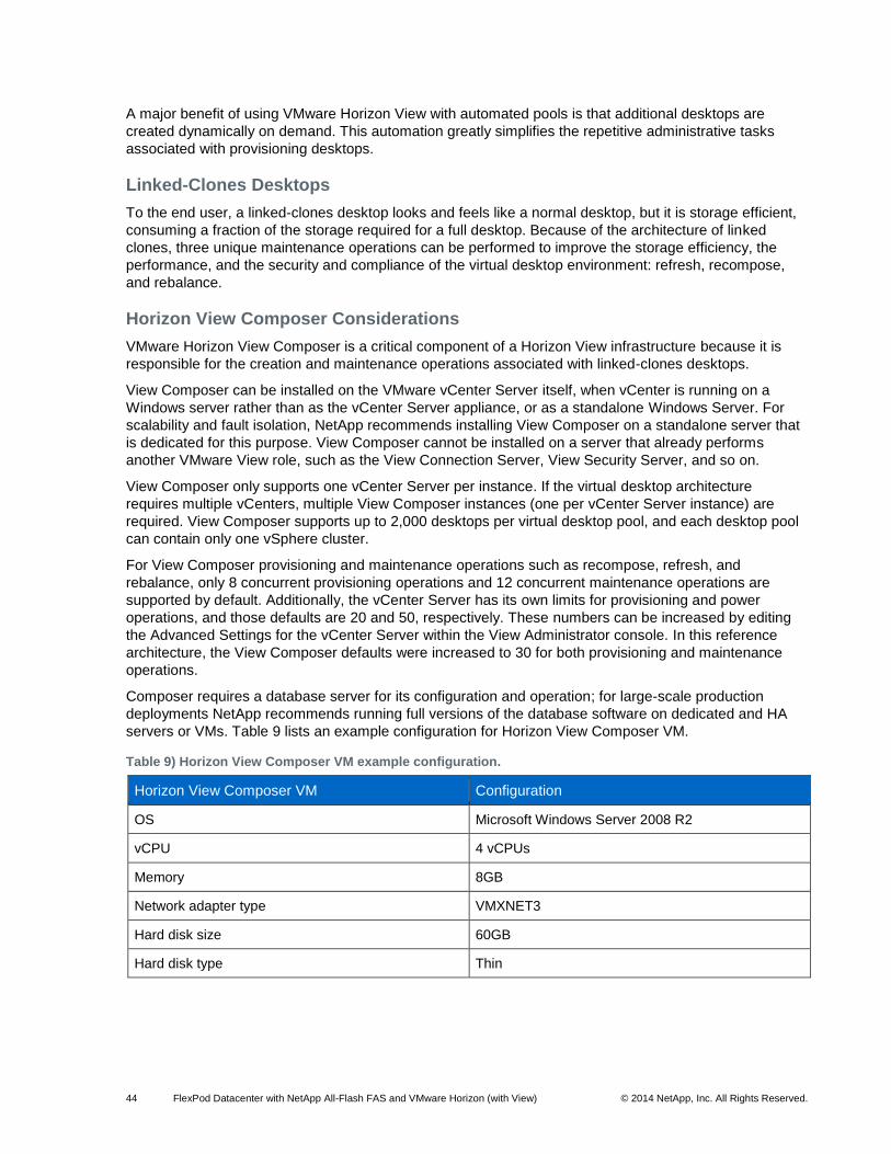
44 FlexPod Datacenter with NetApp All-Flash FAS and VMware Horizon (with View) © 2014 NetApp, Inc. All Rights Reserved.
A major benefit of using VMware Horizon View with automated pools is that additional desktops are
created dynamically on demand. This automation greatly simplifies the repetitive administrative tasks
associated with provisioning desktops.
Linked-Clones Desktops
To the end user, a linked-clones desktop looks and feels like a normal desktop, but it is storage efficient,
consuming a fraction of the storage required for a full desktop. Because of the architecture of linked
clones, three unique maintenance operations can be performed to improve the storage efficiency, the
performance, and the security and compliance of the virtual desktop environment: refresh, recompose,
and rebalance.
Horizon View Composer Considerations
VMware Horizon View Composer is a critical component of a Horizon View infrastructure because it is
responsible for the creation and maintenance operations associated with linked-clones desktops.
View Composer can be installed on the VMware vCenter Server itself, when vCenter is running on a
Windows server rather than as the vCenter Server appliance, or as a standalone Windows Server. For
scalability and fault isolation, NetApp recommends installing View Composer on a standalone server that
is dedicated for this purpose. View Composer cannot be installed on a server that already performs
another VMware View role, such as the View Connection Server, View Security Server, and so on.
View Composer only supports one vCenter Server per instance. If the virtual desktop architecture
requires multiple vCenters, multiple View Composer instances (one per vCenter Server instance) are
required. View Composer supports up to 2,000 desktops per virtual desktop pool, and each desktop pool
can contain only one vSphere cluster.
For View Composer provisioning and maintenance operations such as recompose, refresh, and
rebalance, only 8 concurrent provisioning operations and 12 concurrent maintenance operations are
supported by default. Additionally, the vCenter Server has its own limits for provisioning and power
operations, and those defaults are 20 and 50, respectively. These numbers can be increased by editing
the Advanced Settings for the vCenter Server within the View Administrator console. In this reference
architecture, the View Composer defaults were increased to 30 for both provisioning and maintenance
operations.
Composer requires a database server for its configuration and operation; for large-scale production
deployments NetApp recommends running full versions of the database software on dedicated and HA
servers or VMs. Table 9 lists an example configuration for Horizon View Composer VM.
Table 9) Horizon View Composer VM example configuration.
Horizon View Composer VM Configuration
OS Microsoft Windows Server 2008 R2
vCPU 4 vCPUs
Memory 8GB
Network adapter type VMXNET3
Hard disk size 60GB
Hard disk type Thin
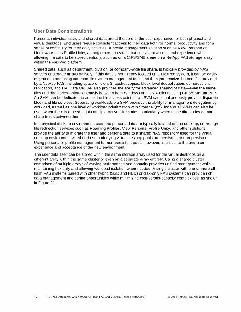
45 FlexPod Datacenter with NetApp All-Flash FAS and VMware Horizon (with View) © 2014 NetApp, Inc. All Rights Reserved.
User Data Considerations
Persona, individual user, and shared data are at the core of the user experience for both physical and
virtual desktops. End users require consistent access to their data both for normal productivity and for a
sense of continuity for their daily activities. A profile management solution such as View Persona or
Liquidware Labs Profile Unity, among others, provides that consistent access and experience while
allowing the data to be stored centrally, such as on a CIFS/SMB share on a NetApp FAS storage array
within the FlexPod platform.
Shared data, such as department, division, or company-wide file share, is typically provided by NAS
servers or storage arrays natively. If this data is not already located on a FlexPod system, it can be easily
migrated to one using common file system management tools and then you receive the benefits provided
by a NetApp FAS, including space-efficient Snapshot copies, block-level deduplication, compression,
replication, and HA. Data ONTAP also provides the ability for advanced sharing of data—even the same
files and directories—simultaneously between both Windows and UNIX clients using CIFS/SMB and NFS.
An SVM can be dedicated to act as the file access point, or an SVM can simultaneously provide disparate
block and file services. Separating workloads via SVM provides the ability for management delegation by
workload, as well as one level of workload prioritization with Storage QoS. Individual SVMs can also be
used when there is a need to join multiple Active Directories, particularly when these directories do not
share trusts between them.
In a physical desktop environment, user and persona data are typically located on the desktop, or through
file redirection services such as Roaming Profiles. View Persona, Profile Unity, and other solutions
provide the ability to migrate the user and persona data to a shared NAS repository used for the virtual
desktop environment whether these underlying virtual desktop pools are persistent or non-persistent.
Using persona or profile management for non-persistent pools, however, is critical to the end-user
experience and acceptance of the new environment.
The user data itself can be stored within the same storage array used for the virtual desktops on a
different array within the same cluster or even on a separate array entirely. Using a shared cluster
comprised of multiple arrays of varying performance and capacity provides unified management while
maintaining flexibility and allowing workload isolation when needed. A single cluster with one or more all-
flash FAS systems paired with other hybrid (SSD and HDD) or disk-only FAS systems can provide rich
data management and tiering opportunities while minimizing cost-versus-capacity complexities, as shown
in Figure 21.
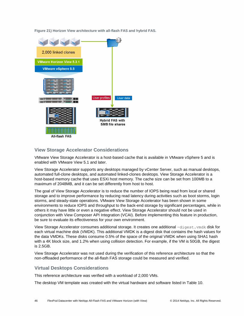
46 FlexPod Datacenter with NetApp All-Flash FAS and VMware Horizon (with View) © 2014 NetApp, Inc. All Rights Reserved.
Figure 21) Horizon View architecture with all-flash FAS and hybrid FAS.
View Storage Accelerator Considerations
VMware View Storage Accelerator is a host-based cache that is available in VMware vSphere 5 and is
enabled with VMware View 5.1 and later.
View Storage Accelerator supports any desktops managed by vCenter Server, such as manual desktops,
automated full-clone desktops, and automated linked-clones desktops. View Storage Accelerator is a
host-based memory cache that uses ESXi host memory. The cache size can be set from 100MB to a
maximum of 2048MB, and it can be set differently from host to host.
The goal of View Storage Accelerator is to reduce the number of IOPS being read from local or shared
storage and to improve performance by reducing read latency during activities such as boot storms, login
storms, and steady-state operations. VMware View Storage Accelerator has been shown in some
environments to reduce IOPS and throughput to the back-end storage by significant percentages, while in
others it may have little or even a negative effect. View Storage Accelerator should not be used in
conjunction with View Composer API Integration (VCAI). Before implementing this feature in production,
be sure to evaluate its effectiveness for your own environment.
View Storage Accelerator consumes additional storage. It creates one additional –digest.vmdk disk for
each virtual machine disk (VMDK). This additional VMDK is a digest disk that contains the hash values for
the data VMDKs. These disks consume 0.5% of the space of the original VMDK when using SHA1 hash
with a 4K block size, and 1.2% when using collision detection. For example, if the VM is 50GB, the digest
is 2.5GB.
View Storage Accelerator was not used during the verification of this reference architecture so that the
non-offloaded performance of the all-flash FAS storage could be measured and verified.
Virtual Desktops Considerations
This reference architecture was verified with a workload of 2,000 VMs.
The desktop VM template was created with the virtual hardware and software listed in Table 10.
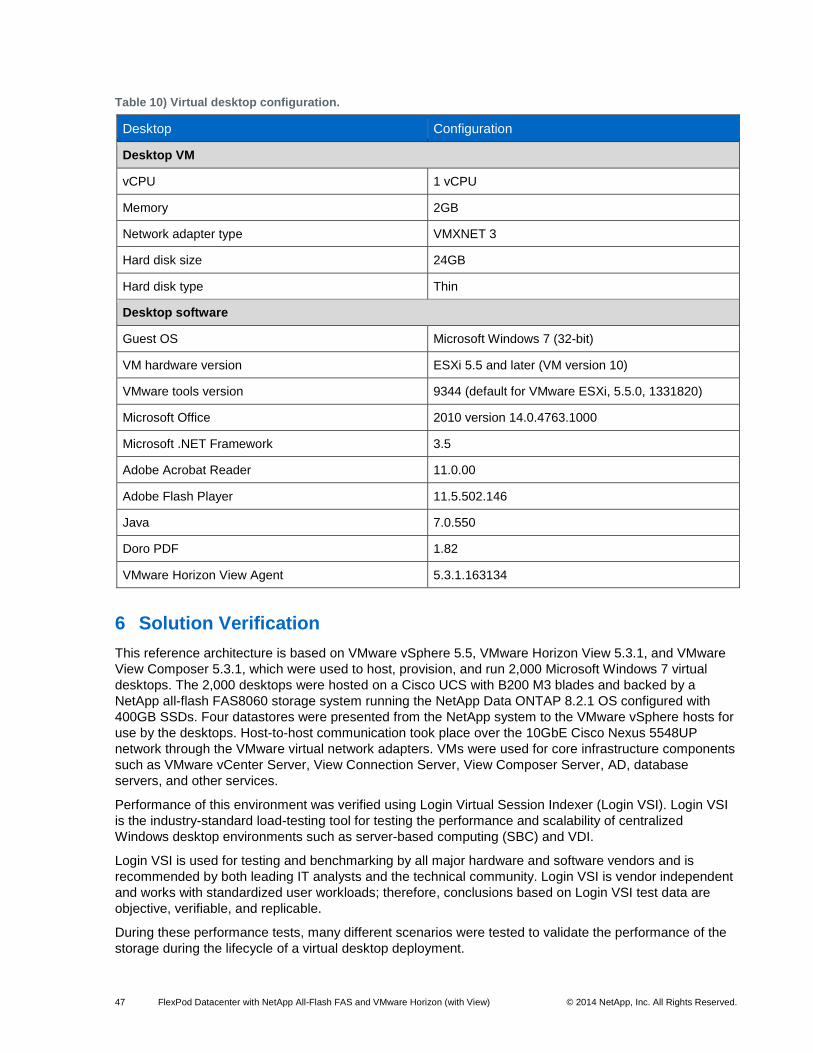
47 FlexPod Datacenter with NetApp All-Flash FAS and VMware Horizon (with View) © 2014 NetApp, Inc. All Rights Reserved.
Table 10) Virtual desktop configuration.
Desktop Configuration
Desktop VM
vCPU 1 vCPU
Memory 2GB
Network adapter type VMXNET 3
Hard disk size 24GB
Hard disk type Thin
Desktop software
Guest OS Microsoft Windows 7 (32-bit)
VM hardware version ESXi 5.5 and later (VM version 10)
VMware tools version 9344 (default for VMware ESXi, 5.5.0, 1331820)
Microsoft Office 2010 version 14.0.4763.1000
Microsoft .NET Framework 3.5
Adobe Acrobat Reader 11.0.00
Adobe Flash Player 11.5.502.146
Java 7.0.550
Doro PDF 1.82
VMware Horizon View Agent 5.3.1.163134
6 Solution Verification
This reference architecture is based on VMware vSphere 5.5, VMware Horizon View 5.3.1, and VMware
View Composer 5.3.1, which were used to host, provision, and run 2,000 Microsoft Windows 7 virtual
desktops. The 2,000 desktops were hosted on a Cisco UCS with B200 M3 blades and backed by a
NetApp all-flash FAS8060 storage system running the NetApp Data ONTAP 8.2.1 OS configured with
400GB SSDs. Four datastores were presented from the NetApp system to the VMware vSphere hosts for
use by the desktops. Host-to-host communication took place over the 10GbE Cisco Nexus 5548UP
network through the VMware virtual network adapters. VMs were used for core infrastructure components
such as VMware vCenter Server, View Connection Server, View Composer Server, AD, database
servers, and other services.
Performance of this environment was verified using Login Virtual Session Indexer (Login VSI). Login VSI
is the industry-standard load-testing tool for testing the performance and scalability of centralized
Windows desktop environments such as server-based computing (SBC) and VDI.
Login VSI is used for testing and benchmarking by all major hardware and software vendors and is
recommended by both leading IT analysts and the technical community. Login VSI is vendor independent
and works with standardized user workloads; therefore, conclusions based on Login VSI test data are
objective, verifiable, and replicable.
During these performance tests, many different scenarios were tested to validate the performance of the
storage during the lifecycle of a virtual desktop deployment.
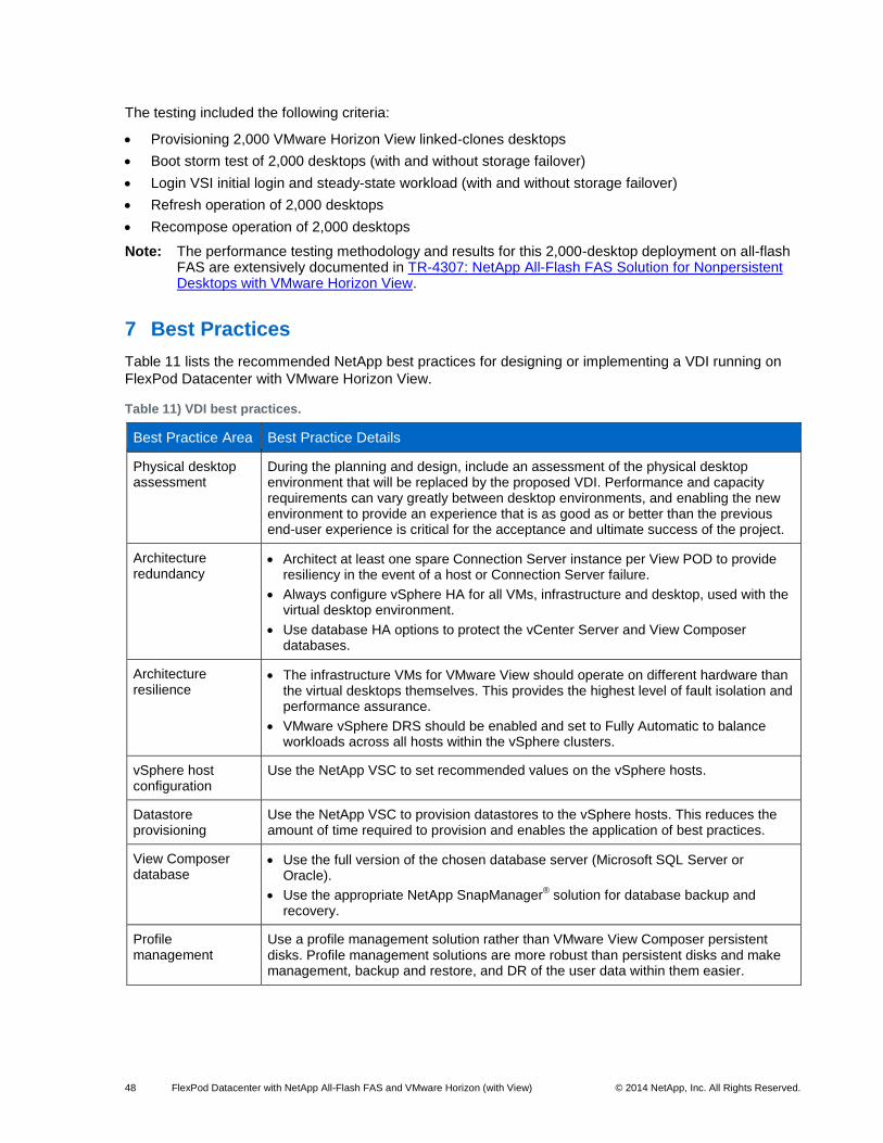
48 FlexPod Datacenter with NetApp All-Flash FAS and VMware Horizon (with View) © 2014 NetApp, Inc. All Rights Reserved.
The testing included the following criteria:
Provisioning 2,000 VMware Horizon View linked-clones desktops
Boot storm test of 2,000 desktops (with and without storage failover)
Login VSI initial login and steady-state workload (with and without storage failover)
Refresh operation of 2,000 desktops
Recompose operation of 2,000 desktops
Note: The performance testing methodology and results for this 2,000-desktop deployment on all-flash FAS are extensively documented in TR-4307: NetApp All-Flash FAS Solution for Nonpersistent Desktops with VMware Horizon View.
7 Best Practices
Table 11 lists the recommended NetApp best practices for designing or implementing a VDI running on
FlexPod Datacenter with VMware Horizon View.
Table 11) VDI best practices.
Best Practice Area Best Practice Details
Physical desktop assessment
During the planning and design, include an assessment of the physical desktop environment that will be replaced by the proposed VDI. Performance and capacity requirements can vary greatly between desktop environments, and enabling the new environment to provide an experience that is as good as or better than the previous end-user experience is critical for the acceptance and ultimate success of the project.
Architecture redundancy
Architect at least one spare Connection Server instance per View POD to provide resiliency in the event of a host or Connection Server failure.
Always configure vSphere HA for all VMs, infrastructure and desktop, used with the virtual desktop environment.
Use database HA options to protect the vCenter Server and View Composer databases.
Architecture resilience
The infrastructure VMs for VMware View should operate on different hardware than the virtual desktops themselves. This provides the highest level of fault isolation and performance assurance.
VMware vSphere DRS should be enabled and set to Fully Automatic to balance workloads across all hosts within the vSphere clusters.
vSphere host configuration
Use the NetApp VSC to set recommended values on the vSphere hosts.
Datastore provisioning
Use the NetApp VSC to provision datastores to the vSphere hosts. This reduces the amount of time required to provision and enables the application of best practices.
View Composer database
Use the full version of the chosen database server (Microsoft SQL Server or Oracle).
Use the appropriate NetApp SnapManager® solution for database backup and
recovery.
Profile management
Use a profile management solution rather than VMware View Composer persistent disks. Profile management solutions are more robust than persistent disks and make management, backup and restore, and DR of the user data within them easier.
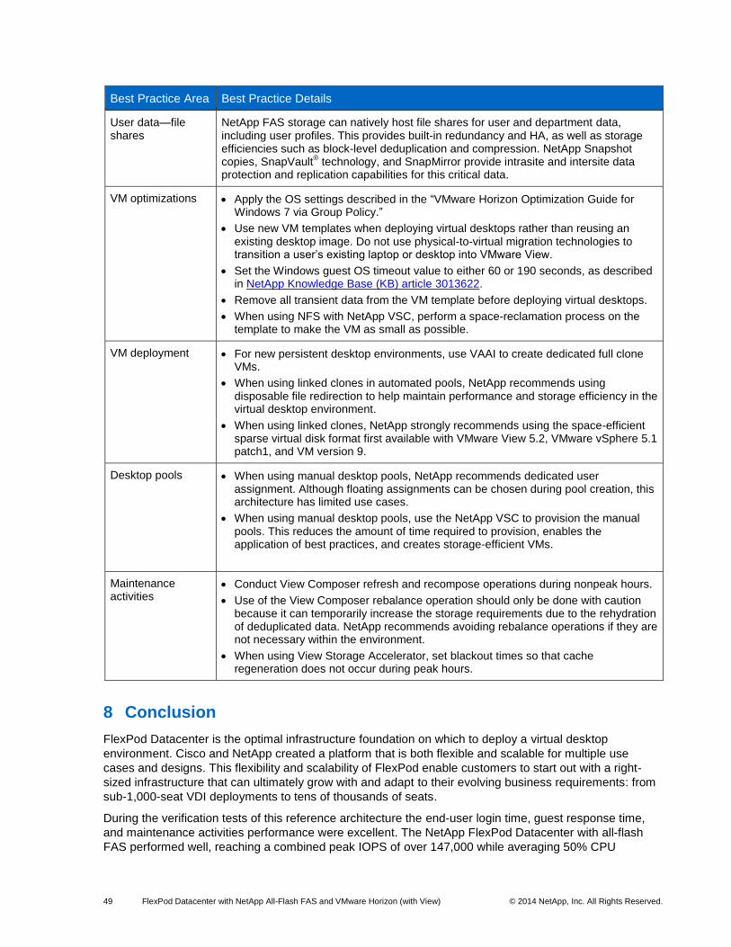
49 FlexPod Datacenter with NetApp All-Flash FAS and VMware Horizon (with View) © 2014 NetApp, Inc. All Rights Reserved.
Best Practice Area Best Practice Details
User data—file shares
NetApp FAS storage can natively host file shares for user and department data, including user profiles. This provides built-in redundancy and HA, as well as storage efficiencies such as block-level deduplication and compression. NetApp Snapshot copies, SnapVault
® technology, and SnapMirror provide intrasite and intersite data
protection and replication capabilities for this critical data.
VM optimizations Apply the OS settings described in the “VMware Horizon Optimization Guide for Windows 7 via Group Policy.”
Use new VM templates when deploying virtual desktops rather than reusing an existing desktop image. Do not use physical-to-virtual migration technologies to transition a user’s existing laptop or desktop into VMware View.
Set the Windows guest OS timeout value to either 60 or 190 seconds, as described in NetApp Knowledge Base (KB) article 3013622.
Remove all transient data from the VM template before deploying virtual desktops.
When using NFS with NetApp VSC, perform a space-reclamation process on the template to make the VM as small as possible.
VM deployment For new persistent desktop environments, use VAAI to create dedicated full clone VMs.
When using linked clones in automated pools, NetApp recommends using disposable file redirection to help maintain performance and storage efficiency in the virtual desktop environment.
When using linked clones, NetApp strongly recommends using the space-efficient sparse virtual disk format first available with VMware View 5.2, VMware vSphere 5.1 patch1, and VM version 9.
Desktop pools When using manual desktop pools, NetApp recommends dedicated user assignment. Although floating assignments can be chosen during pool creation, this architecture has limited use cases.
When using manual desktop pools, use the NetApp VSC to provision the manual pools. This reduces the amount of time required to provision, enables the application of best practices, and creates storage-efficient VMs.
Maintenance activities
Conduct View Composer refresh and recompose operations during nonpeak hours.
Use of the View Composer rebalance operation should only be done with caution because it can temporarily increase the storage requirements due to the rehydration of deduplicated data. NetApp recommends avoiding rebalance operations if they are not necessary within the environment.
When using View Storage Accelerator, set blackout times so that cache regeneration does not occur during peak hours.
8 Conclusion
FlexPod Datacenter is the optimal infrastructure foundation on which to deploy a virtual desktop
environment. Cisco and NetApp created a platform that is both flexible and scalable for multiple use
cases and designs. This flexibility and scalability of FlexPod enable customers to start out with a right-
sized infrastructure that can ultimately grow with and adapt to their evolving business requirements: from
sub-1,000-seat VDI deployments to tens of thousands of seats.
During the verification tests of this reference architecture the end-user login time, guest response time,
and maintenance activities performance were excellent. The NetApp FlexPod Datacenter with all-flash
FAS performed well, reaching a combined peak IOPS of over 147,000 while averaging 50% CPU
50 FlexPod Datacenter with NetApp All-Flash FAS and VMware Horizon (with View) © 2014 NetApp, Inc. All Rights Reserved.
utilization during most operations. All test categories demonstrated that, based on the 2,000-user
workload and maintenance operations, this FlexPod Datacenter with NetApp all-flash FAS8060 system
should be capable of doubling the workload to 4,000 users while still being able to perform appropriately
even in the event of a storage, host, or network failure.
Acknowledgements
This document is the result of the work, documentation, and assistance provided by Chris Gebhardt,
Chad Morgenstern, Rachel Zhu, John George, and Arvind Ramakrishnan, all of NetApp. The author
would like to thank Mike Brennan of Cisco, Bhumik Patel of VMware, and Troy Mangum and Abhinav
Joshi of NetApp for their contributions and support.
References
This section provides links to additional information and reference material for the subjects contained in
this document.
Cisco UCS
The following links provide additional information about the Cisco UCS:
Cisco Design Zone for Data Centers http://www.cisco.com/c/en/us/solutions/enterprise/design-zone-data-centers/index.html
Cisco UCS http://www.cisco.com/c/en/us/products/servers-unified-computing/index.html
Cisco UCS 6200 Series Fabric Interconnects http://www.cisco.com/en/US/products/ps11544/index.html
Cisco UCS 5100 Series Blade Server Chassis http://www.cisco.com/en/US/products/ps10279/index.html
Cisco UCS B-Series Blade Servers http://www.cisco.com/c/en/us/products/servers-unified-computing/ucs-b-series-blade-servers/index.html
Cisco UCS Adapters http://www.cisco.com/en/US/products/ps10277/prod_module_series_home.html
Cisco UCS Manager http://www.cisco.com/en/US/products/ps10281/index.html
Cisco Nexus Networking
The following links provide additional information about Cisco Nexus 5000 Series switches:
Cisco Nexus 5000 Series Switches http://www.cisco.com/en/US/products/ps9670/index.html
Cisco Nexus 5000 Series Switches Design Guides http://www.cisco.com/en/US/products/ps9670/products_implementation_design_guides_list.html
NetApp FAS Storage
The following links provide additional information about NetApp FAS storage:
Clustered Data ONTAP 8.2.1 Documentation http://mysupport.netapp.com/documentation/docweb/index.html?productID=61820
51 FlexPod Datacenter with NetApp All-Flash FAS and VMware Horizon (with View) © 2014 NetApp, Inc. All Rights Reserved.
TR-3982: NetApp Clustered Data ONTAP 8.2 http://www.netapp.com/us/media/tr-3982.pdf
TR-3705: NetApp and VMware View Solution Guide http://www.netapp.com/us/media/tr-3705.pdf
TR-4181: VMware Horizon View 5 Solutions Guide http://www.netapp.com/us/media/tr-4181.pdf
TR-3949: NetApp and VMware View 5,000-Seat Performance Report http://www.netapp.com/us/media/tr-3949.pdf
Guest OS Tunings for a VMware vSphere Environment (KB) https://kb.netapp.com/support/index?page=content&id=3013622
TR-4068: VMware vSphere 5 on NetApp Clustered Data ONTAP http://www.netapp.com/us/media/tr-4068.pdf
TR-4307: NetApp All-Flash FAS Solution for Nonpersistent Desktops with VMware Horizon View http://www.netapp.com/us/media/tr-4307.pdf
VMware vSphere
The following links provide additional information about VMware vSphere:
VMware vSphere Documentation Center http://pubs.vmware.com/vsphere-55/index.jsp
Enabling Microsoft SQL Clustering Service in VMware vCenter Server 5.5 (KB) http://kb.vmware.com/kb/2059560
Configuring Tomcat Server Settings in VMware vCenter Server 5.1 and 5.5 (KB) http://kb.vmware.com/kb/2021302
VMware Horizon View
The following links provide additional information about VMware Horizon View:
VMware Horizon View 5.2 and 5.3 Documentation Center http://pubs.vmware.com/view-52/index.jsp
VMware Horizon View Best Practices (KB) http://kb.vmware.com/kb/1020305
VMware Horizon View 5.2 Performance and Best Practices (PDF) http://www.vmware.com/files/pdf/view/vmware-horizon-view-best-practices-performance-study.pdf
Interoperability Matrices
The following links provide information about interoperability tools:
Cisco UCS Hardware and Software Interoperability Tool http://www.cisco.com/web/techdoc/ucs/interoperability/matrix/matrix.html
NetApp Interoperability Matrix Tool http://support.netapp.com/matrix
VMware Compatibility Guide http://www.vmware.com/resources/compatibility
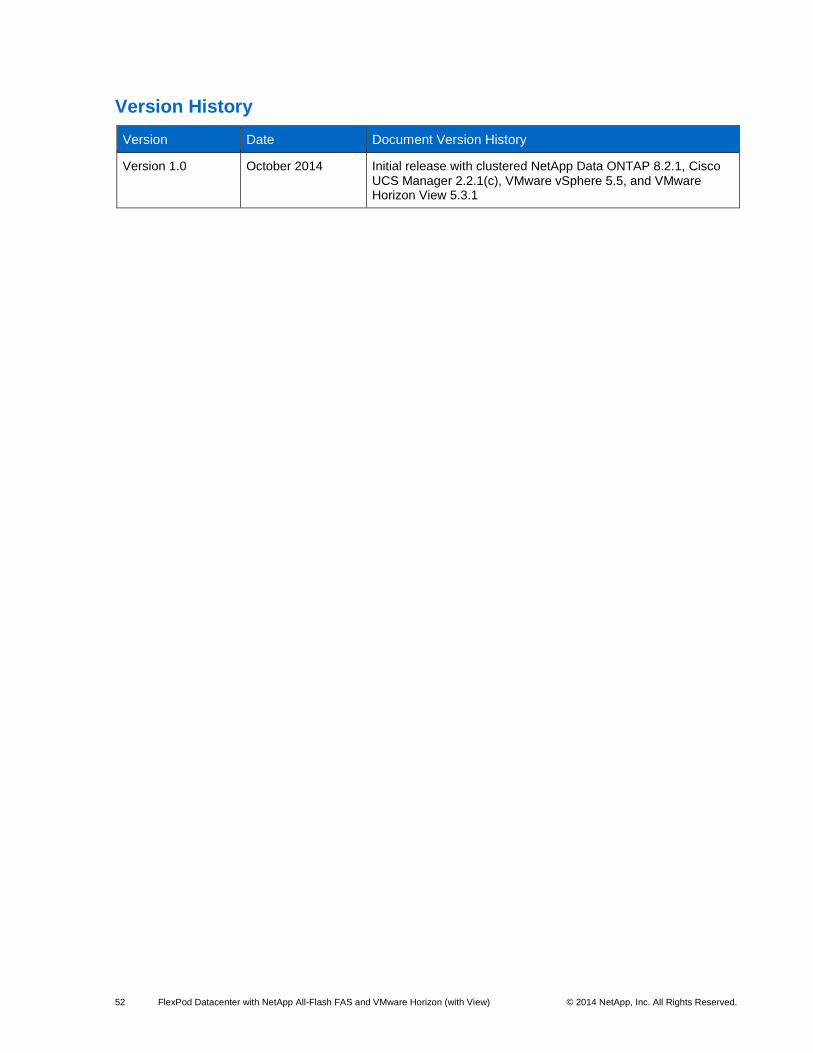
52 FlexPod Datacenter with NetApp All-Flash FAS and VMware Horizon (with View) © 2014 NetApp, Inc. All Rights Reserved.
Version History
Version Date Document Version History
Version 1.0 October 2014 Initial release with clustered NetApp Data ONTAP 8.2.1, Cisco UCS Manager 2.2.1(c), VMware vSphere 5.5, and VMware Horizon View 5.3.1
53 FlexPod Datacenter with NetApp All-Flash FAS and VMware Horizon (with View) © 2014 NetApp, Inc. All Rights Reserved.
Refer to the Interoperability Matrix Tool (IMT) on the NetApp Support site to validate that the exact product and feature versions described in this document are supported for your specific environment. The NetApp IMT defines the product components and versions that can be used to construct configurations that are supported by NetApp. Specific results depend on each customer's installation in accordance with published specifications.
Trademark Information
NetApp, the NetApp logo, Go Further, Faster, ASUP, AutoSupport, Campaign Express, Cloud ONTAP, Customer Fitness, Data ONTAP, DataMotion, Fitness, Flash Accel, Flash Cache, Flash Pool, FlashRay, FlexArray, FlexCache, FlexClone, FlexPod, FlexScale, FlexShare, FlexVol, FPolicy, GetSuccessful, LockVault, Manage ONTAP, Mars, MetroCluster, MultiStore, NetApp Insight, OnCommand, ONTAP, ONTAPI, RAID DP, SANtricity, SecureShare, Simplicity, Simulate ONTAP, Snap Creator, SnapCopy, SnapDrive, SnapIntegrator, SnapLock, SnapManager, SnapMirror, SnapMover, SnapProtect, SnapRestore, Snapshot, SnapValidator, SnapVault, StorageGRID, Tech OnTap, Unbound Cloud, and WAFL are trademarks or registered trademarks of NetApp, Inc., in the United States and/or other countries. A current list of NetApp trademarks is available on the Web at http://www.netapp.com/us/legal/netapptmlist.aspx.
Cisco and the Cisco logo are trademarks of Cisco in the U.S. and other countries. All other brands or products are trademarks or registered trademarks of their respective holders and should be treated as such.
NVA-1110-FP-DESIGN
Copyright Information
Copyright © 1994–2014 NetApp, Inc. All rights reserved. Printed in the U.S. No part of this document covered by copyright may be reproduced in any form or by any means—graphic, electronic, or mechanical, including photocopying, recording, taping, or storage in an electronic retrieval system—without prior written permission of the copyright owner.
Software derived from copyrighted NetApp material is subject to the following license and disclaimer:
THIS SOFTWARE IS PROVIDED BY NETAPP "AS IS" AND WITHOUT ANY EXPRESS OR IMPLIED WARRANTIES, INCLUDING, BUT NOT LIMITED TO, THE IMPLIED WARRANTIES OF MERCHANTABILITY AND FITNESS FOR A PARTICULAR PURPOSE, WHICH ARE HEREBY DISCLAIMED. IN NO EVENT SHALL NETAPP BE LIABLE FOR ANY DIRECT, INDIRECT, INCIDENTAL, SPECIAL, EXEMPLARY, OR CONSEQUENTIAL DAMAGES (INCLUDING, BUT NOT LIMITED TO, PROCUREMENT OF SUBSTITUTE GOODS OR SERVICES; LOSS OF USE, DATA, OR PROFITS; OR BUSINESS INTERRUPTION) HOWEVER CAUSED AND ON ANY THEORY OF LIABILITY, WHETHER IN CONTRACT, STRICT LIABILITY, OR TORT (INCLUDING NEGLIGENCE OR OTHERWISE) ARISING IN ANY WAY OUT OF THE USE OF THIS SOFTWARE, EVEN IF ADVISED OF THE POSSIBILITY OF SUCH DAMAGE.
NetApp reserves the right to change any products described herein at any time, and without notice. NetApp assumes no responsibility or liability arising from the use of products described herein, except as expressly agreed to in writing by NetApp. The use or purchase of this product does not convey a license under any patent rights, trademark rights, or any other intellectual property rights of NetApp.
The product described in this manual may be protected by one or more U.S. patents, foreign patents, or pending applications.
RESTRICTED RIGHTS LEGEND: Use, duplication, or disclosure by the government is subject to restrictions as set forth in subparagraph (c)(1)(ii) of the Rights in Technical Data and Computer Software clause at DFARS 252.277-7103 (October 1988) and FAR 52-227-19 (June 1987).