Embed Size (px)
Citation preview

Technical Report
FlexPod Express with VMware vSphere 5.1u1 Implementation Guide
Karthick Radhakrishnan, Arvind Ramakrishnan, Lindsey Street, NetApp
Jeffrey Fultz, Cisco
March 2014 | TR-4261

2 FlexPod Express with VMware vSphere 5.1u1 Implementation Guide © 2014 NetApp, Inc. All Rights Reserved.
TABLE OF CONTENTS
1 Overview ................................................................................................................................................ 7
2 Audience ................................................................................................................................................ 7
3 Architecture ........................................................................................................................................... 7
3.1 Small Configuration .........................................................................................................................................7
3.2 Medium Configuration .....................................................................................................................................8
4 Hardware Details ................................................................................................................................... 9
4.1 Small Configuration .........................................................................................................................................9
4.2 Medium Configuration ................................................................................................................................... 10
5 Software Details .................................................................................................................................. 10
6 Configuration Guidelines ................................................................................................................... 10
7 FlexPod Express Cabling Information .............................................................................................. 18
7.1 Small Configuration Cabling for Clustered Data ONTAP and 7-Mode .......................................................... 18
7.2 Medium Configuration Cabling Diagrams for Clustered Data ONTAP and 7-Mode ...................................... 21
8 Cisco Nexus 3048 Deployment Procedure ...................................................................................... 26
8.1 Initial Setup of the Cisco Nexus 3048 Switches ............................................................................................ 26
8.2 Software Upgrade (Optional) ........................................................................................................................ 27
8.3 Features ........................................................................................................................................................ 27
8.4 Global PortChannel Configuration ................................................................................................................ 27
8.5 Global Spanning-Tree Configuration ............................................................................................................. 28
8.6 Jumbo Frames .............................................................................................................................................. 28
8.7 VLAN Definitions ........................................................................................................................................... 28
8.8 Access and Management Port Descriptions ................................................................................................. 29
8.9 Server and Storage Management Interface Configuration ............................................................................ 29
8.10 Virtual PortChannel Global Configuration ..................................................................................................... 30
8.11 Storage PortChannels ................................................................................................................................... 31
8.12 Server Connections ...................................................................................................................................... 31
8.13 In-Band Management SVI Configuration ...................................................................................................... 32
8.14 Uplink to Existing Network Infrastructure ...................................................................................................... 33
9 NetApp FAS Storage Deployment Procedure .................................................................................. 33
9.1 NetApp FAS2200 Series Controller .............................................................................................................. 33
9.2 NetApp Hardware Universe .......................................................................................................................... 33
9.3 Clustered Data ONTAP 8.2 ........................................................................................................................... 34
3 FlexPod Express with VMware vSphere 5.1u1 Implementation Guide © 2014 NetApp, Inc. All Rights Reserved.
9.4 Cluster Creation in Clustered Data ONTAP .................................................................................................. 37
9.5 Cluster Join in Clustered Data ONTAP ......................................................................................................... 40
9.6 Log into the Cluster ....................................................................................................................................... 42
9.7 Zeroing All Spare Disks ................................................................................................................................ 42
9.8 Auto-Revert Setup for Cluster Management ................................................................................................. 42
9.9 IFGRP LACP in Clustered Data ONTAP ....................................................................................................... 42
9.10 VLANs in Clustered Data ONTAP ................................................................................................................. 42
9.11 Failover Group Management in Clustered Data ONTAP .............................................................................. 42
9.12 Assigning a Management Failover Group to the Cluster Management LIF ................................................... 43
9.13 Failover Group Node Management in Clustered Data ONTAP ..................................................................... 43
9.14 Assigning a Node Management Failover Group to the Node Management LIF ............................................ 43
9.15 Aggregates.................................................................................................................................................... 43
9.16 Service Processor ......................................................................................................................................... 43
9.17 Storage Failover in Clustered Data ONTAP .................................................................................................. 45
9.18 Jumbo Frames in Clustered Data ONTAP .................................................................................................... 45
9.19 NTP in Clustered Data ONTAP ..................................................................................................................... 45
9.20 SNMP in Clustered Data ONTAP .................................................................................................................. 46
9.21 SNMPv1 in Clustered Data ONTAP .............................................................................................................. 46
9.22 SNMPv3 in Clustered Data ONTAP .............................................................................................................. 46
9.23 AutoSupport HTTPS in Clustered Data ONTAP ........................................................................................... 46
9.24 Cisco Discovery Protocol in Clustered Data ONTAP .................................................................................... 47
9.25 Vserver.......................................................................................................................................................... 47
9.26 Creating Load-Sharing Mirror of the Vserver Root Volume in Clustered Data ONTAP ................................. 48
9.27 iSCSI Service in Clustered Data ONTAP ...................................................................................................... 48
9.28 HTTPS Access in Clustered Data ONTAP .................................................................................................... 48
9.29 NFSv3 in Clustered Data ONTAP ................................................................................................................. 49
9.30 NetApp FlexVol in Clustered Data ONTAP ................................................................................................... 49
9.31 Deduplication in Clustered Data ONTAP ...................................................................................................... 50
9.32 NFS Failover Group in Clustered Data ONTAP ............................................................................................ 50
9.33 NFS LIF in Clustered Data ONTAP ............................................................................................................... 50
9.34 Failover Group for Vserver Management in Clustered Data ONTAP ............................................................ 50
9.35 Adding an Infrastructure Vserver Administrator ............................................................................................ 50
9.36 Data ONTAP 8.2 Operating in 7-Mode ......................................................................................................... 50
9.37 Running the Setup Process .......................................................................................................................... 54
9.38 Upgrading the Service Processor on Each Node to the Latest Release ....................................................... 58
9.39 Aggregates in Data ONTAP 7-Mode ............................................................................................................. 58
4 FlexPod Express with VMware vSphere 5.1u1 Implementation Guide © 2014 NetApp, Inc. All Rights Reserved.
9.40 IFGRP LACP ................................................................................................................................................. 58
9.41 VLANs ........................................................................................................................................................... 58
9.42 IP Config ....................................................................................................................................................... 58
9.43 NFSv3 ........................................................................................................................................................... 59
9.44 Active-Active Controller Configuration .......................................................................................................... 59
9.45 Data ONTAP SecureAdmin........................................................................................................................... 59
9.46 Secure Shell .................................................................................................................................................. 60
9.47 SNMP ........................................................................................................................................................... 61
9.48 SNMPv1 ........................................................................................................................................................ 61
9.49 SNMPv3 ........................................................................................................................................................ 61
9.50 AutoSupport HTTPS ..................................................................................................................................... 61
9.51 Security Best Practices ................................................................................................................................. 61
9.52 Enabling Network Data Management Protocol ............................................................................................. 62
9.53 Creating NetApp FlexVol Volumes ................................................................................................................ 62
9.54 NFS Exports .................................................................................................................................................. 62
9.55 Enabling Cisco Discovery Protocol ............................................................................................................... 62
10 Cisco UCS C-Series Rack Servers Deployment Procedure ........................................................... 62
10.1 Performing Initial Cisco UCS C-Series Standalone Server Setup for Cisco IMC .......................................... 63
10.2 Configuring Cisco UCS C-Series RAID Settings ........................................................................................... 64
11 VMware ESXi Deployment Procedure .............................................................................................. 68
11.1 Logging into Cisco UCS C-Series Standalone Server Interface for Cisco IMC ............................................. 68
11.2 Setting Up the VMware ESXi Installation ...................................................................................................... 69
11.3 Installing VMware ESXi ................................................................................................................................. 69
11.4 Setting Up Management Networking for the VMware ESXi Hosts ................................................................ 69
11.5 Downloading the VMware vSphere Client and Remote Command Line ....................................................... 71
11.6 Logging into the VMware ESXi Hosts Using the VMware vSphere Client ..................................................... 71
11.7 Setting Up VMkernel Ports and the Virtual Switch ........................................................................................ 71
11.8 Mounting the Required Datastores ............................................................................................................... 72
11.9 Moving the Virtual Machine Swapfile Location .............................................................................................. 73
12 VMware vCenter 5.1 Update 1 Deployment Procedure ................................................................... 73
12.1 Building a VMware vCenter Virtual Machine ................................................................................................. 73
12.2 Installing VMware vCenter Server ................................................................................................................. 75
12.3 Setting Up VMware vCenter Server .............................................................................................................. 79
12.4 Setting Up a Microsoft Windows Template ................................................................................................... 81
13 NetApp Virtual Storage Console 4.2.1 Deployment Procedure ..................................................... 81
5 FlexPod Express with VMware vSphere 5.1u1 Implementation Guide © 2014 NetApp, Inc. All Rights Reserved.
13.1 NetApp VSC 4.2.1 Preinstallation Considerations ........................................................................................ 81
13.2 Installing NetApp VSC 4.2.1.......................................................................................................................... 81
13.3 Registering NetApp VSC with VMware vCenter Server ................................................................................ 83
13.4 Discovering and Adding Storage Resources................................................................................................. 84
13.5 Configuring Optimal Storage Settings for VMware ESXi Hosts..................................................................... 86
13.6 NetApp VSC 4.2.1 Provisioning and Cloning Setup (Data ONTAP 7-Mode Only) ........................................ 87
13.7 NetApp VSC 4.2.1 Backup and Recovery ..................................................................................................... 89
14 Bill of Materials ................................................................................................................................... 95
15 Quick Deployment of FlexPod Express with Cisco UCS Director ................................................. 97
LIST OF TABLES
Table 1) Small configuration details. ..............................................................................................................................9
Table 2) Medium configuration details. ......................................................................................................................... 10
Table 3) Software details. ............................................................................................................................................. 10
Table 4) VLANs. ........................................................................................................................................................... 11
Table 5) VMware virtual machines created. ................................................................................................................. 11
Table 6) Deployment guide variables for clustered Data ONTAP and 7-Mode implementations.................................. 11
Table 7) Cisco Nexus 3048 switch 1. ........................................................................................................................... 20
Table 8) Cisco Nexus 3048 switch 2. .......................................................................................................................... 20
Table 9) NetApp storage controller 1 (clustered Data ONTAP only). ........................................................................... 21
Table 10) NetApp storage controller 2 (clustered Data ONTAP only). ......................................................................... 21
Table 11) Cisco Nexus 3048 A cabling information. ..................................................................................................... 23
Table 12) Cisco Nexus 3048 B cabling information. ..................................................................................................... 24
Table 13) NetApp storage controller 1 (clustered Data ONTAP Only). ......................................................................... 25
Table 14) NetApp storage controller 2 (clustered Data ONTAP Only). ......................................................................... 25
Table 15) NetApp FAS2200 series controller prerequisites. ........................................................................................ 33
Table 16) Small configuration components. ................................................................................................................. 95
Table 17 Medium configuration components. ............................................................................................................... 96
LIST OF FIGURES
Figure 1) FlexPod Express small configuration. .............................................................................................................8
Figure 2) FlexPod Express medium configuration. .........................................................................................................9
Figure 3) Clustered Data ONTAP cabling diagram. ...................................................................................................... 19
Figure 4) Data ONTAP 7-Mode cabling diagram. ......................................................................................................... 19
Figure 5) Clustered Data ONTAP cabling diagram. ...................................................................................................... 22
Figure 6) Data ONTAP 7-Mode cabling diagram. ......................................................................................................... 23

6 FlexPod Express with VMware vSphere 5.1u1 Implementation Guide © 2014 NetApp, Inc. All Rights Reserved.
7 FlexPod Express with VMware vSphere 5.1u1 Implementation Guide © 2014 NetApp, Inc. All Rights Reserved.
1 Overview
The small and medium FlexPod® Express configurations are low-cost, standardized infrastructure
solutions developed to meet the needs of small and midsize businesses. The configurations have been
built and tested to deliver a cost-effective, high-value, and best practice architecture. Each configuration
provides a standardized base platform capable of running a number of business-critical applications while
providing scalability options to enable the infrastructure to grow with business demands.
Cisco UCS® Director delivers unified converged infrastructure management for administering computing,
networking, virtualization, and storage resources from a single web interface. For instructions on how to set up the Cisco UCS Director software, refer to http://www.cisco.com/c/en/us/solutions/collateral/data-center-virtualization/unified-computing/whitepaper-c11-731143.html.
2 Audience
This document describes the architecture and deployment procedures for both small and medium FlexPod Express configurations with a choice of NetApp clustered Data ONTAP
® or Data ONTAP
operating in 7-Mode. The intended audience for this document includes, but is not limited to, sales engineers, field consultants, professional services, IT managers, partner engineering, and customers who want to deploy FlexPod Express.
3 Architecture
Both the small and medium FlexPod Express configurations use Cisco UCS C-Series Rack Servers,
Cisco Nexus® switches, and NetApp FAS storage (clustered Data ONTAP switchless or Data ONTAP 7-
Mode). Although FlexPod Express supports an open ecosystem of virtualization and management
software solutions, the architecture described in this document specifically includes VMware vSphere®
virtualization and Cisco UCS Director. NetApp strongly recommends virtualization software and
infrastructure management software as part of every FlexPod Express deployment. Each configuration
uses the best practices for and between each component to enable a reliable, enterprise-class
infrastructure.
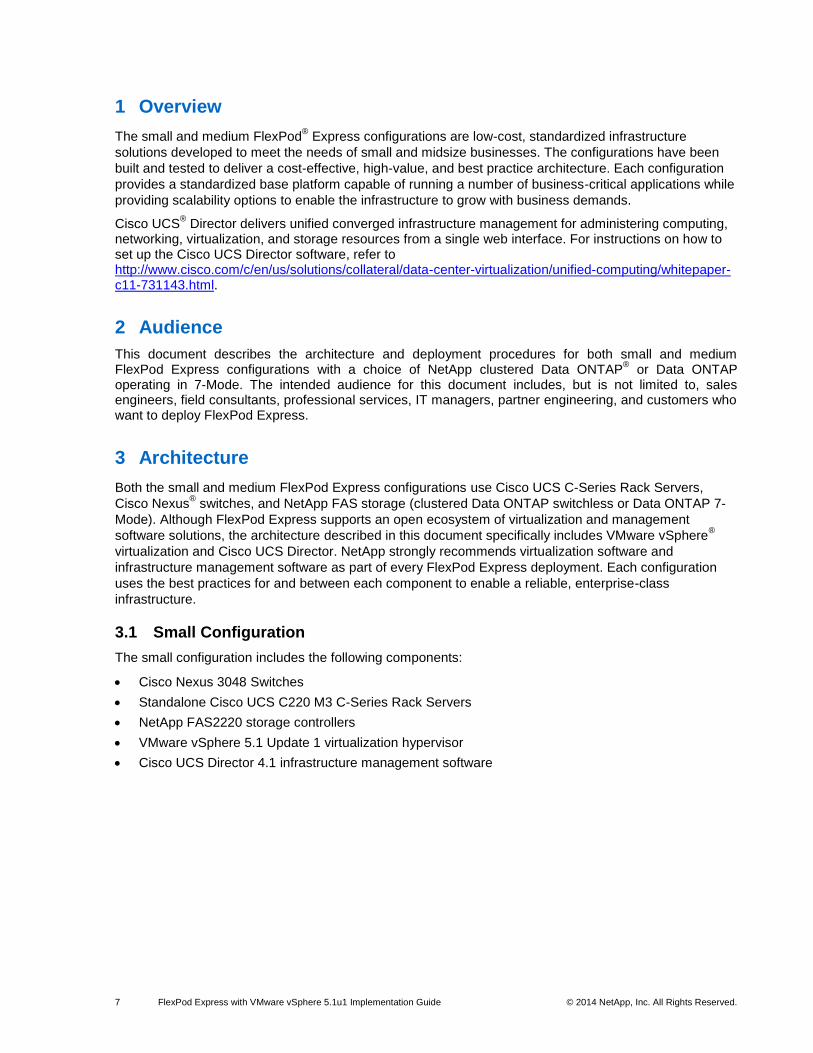
3.1 Small Configuration
The small configuration includes the following components:
Cisco Nexus 3048 Switches
Standalone Cisco UCS C220 M3 C-Series Rack Servers
NetApp FAS2220 storage controllers
VMware vSphere 5.1 Update 1 virtualization hypervisor
Cisco UCS Director 4.1 infrastructure management software
8 FlexPod Express with VMware vSphere 5.1u1 Implementation Guide © 2014 NetApp, Inc. All Rights Reserved.
Figure 1 shows the physical topology of the small FlexPod Express configuration.
Figure 1) FlexPod Express small configuration.
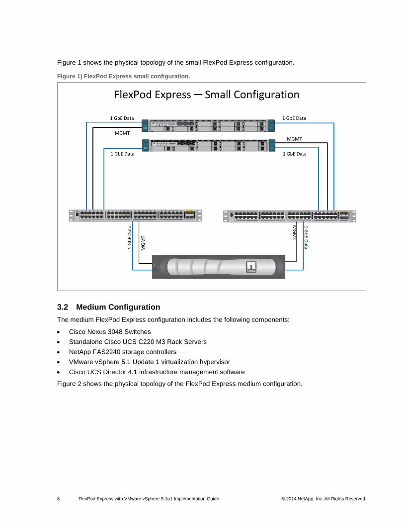
3.2 Medium Configuration
The medium FlexPod Express configuration includes the following components:
Cisco Nexus 3048 Switches
Standalone Cisco UCS C220 M3 Rack Servers
NetApp FAS2240 storage controllers
VMware vSphere 5.1 Update 1 virtualization hypervisor
Cisco UCS Director 4.1 infrastructure management software
Figure 2 shows the physical topology of the FlexPod Express medium configuration.
9 FlexPod Express with VMware vSphere 5.1u1 Implementation Guide © 2014 NetApp, Inc. All Rights Reserved.
Figure 2) FlexPod Express medium configuration.
4 Hardware Details
4.1 Small Configuration
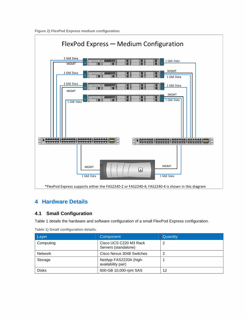
Table 1 details the hardware and software configuration of a small FlexPod Express configuration.
Table 1) Small configuration details.
Layer Component Quantity
Computing Cisco UCS C220 M3 Rack Servers (standalone)
2
Network Cisco Nexus 3048 Switches 2
Storage NetApp FAS2220A (high-availability pair)
1
Disks 600-GB 10,000-rpm SAS 12
10 FlexPod Express with VMware vSphere 5.1u1 Implementation Guide © 2014 NetApp, Inc. All Rights Reserved.
4.2 Medium Configuration
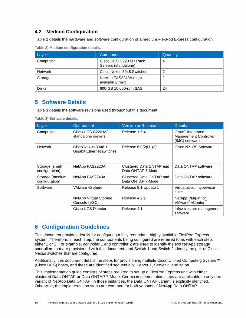
Table 2 details the hardware and software configuration of a medium FlexPod Express configuration.
Table 2) Medium configuration details.
Layer Component Quantity
Computing Cisco UCS C220 M3 Rack Servers (standalone)
4
Network Cisco Nexus 3048 Switches 2
Storage NetApp FAS2240A (high-availability pair)
1
Disks 600-GB 10,000-rpm SAS 24
5 Software Details
Table 3 details the software revisions used throughout this document.
Table 3) Software details.
Layer Component Version or Release Details Computing Cisco UCS C220 M3
standalone servers Release 1.5.4 Cisco
® Integrated
Management Controller (IMC) software
Network Cisco Nexus 3048 1 Gigabit Ethernet switches
Release 6.0(2)U1(3) Cisco NX-OS Software
Storage (small configuration)
NetApp FAS2220A Clustered Data ONTAP and Data ONTAP 7-Mode
Data ONTAP software
Storage (medium configuration)
NetApp FAS2240A Clustered Data ONTAP and Data ONTAP 7-Mode
Data ONTAP software
Software VMware vSphere Release 5.1 Update 1 Virtualization hypervisor suite
NetApp Virtual Storage Console (VSC)
Release 4.2.1 NetApp Plug-in for VMware
® vCenter
™
Cisco UCS Director Release 4.1 Infrastructure management software
6 Configuration Guidelines
This document provides details for configuring a fully redundant, highly available FlexPod Express system. Therefore, in each step, the components being configured are referred to as with each step, either 1 or 2. For example, controller 1 and controller 2 are used to identify the two NetApp storage controllers that are provisioned with this document, and Switch 1 and Switch 2 identify the pair of Cisco Nexus switches that are configured.
Additionally, this document details the steps for provisioning multiple Cisco Unified Computing System™ (Cisco UCS) hosts, and these are identified sequentially: Server 1, Server 2, and so on.
This implementation guide consists of steps required to set up a FlexPod Express unit with either clustered Data ONTAP or Data ONTAP 7-Mode. Certain implementation steps are applicable to only one variant of NetApp Data ONTAP; in those instances, the Data ONTAP variant is explicitly identified. Otherwise, the implementation steps are common for both variants of NetApp Data ONTAP.
11 FlexPod Express with VMware vSphere 5.1u1 Implementation Guide © 2014 NetApp, Inc. All Rights Reserved.
To indicate that you should include information pertinent to your environment in a given step,
<<var_text>> appears as part of the command structure. See the following example for the vlan
create command:
controller1>vlan create vif0 <<var_mgmt_vlan_id>>
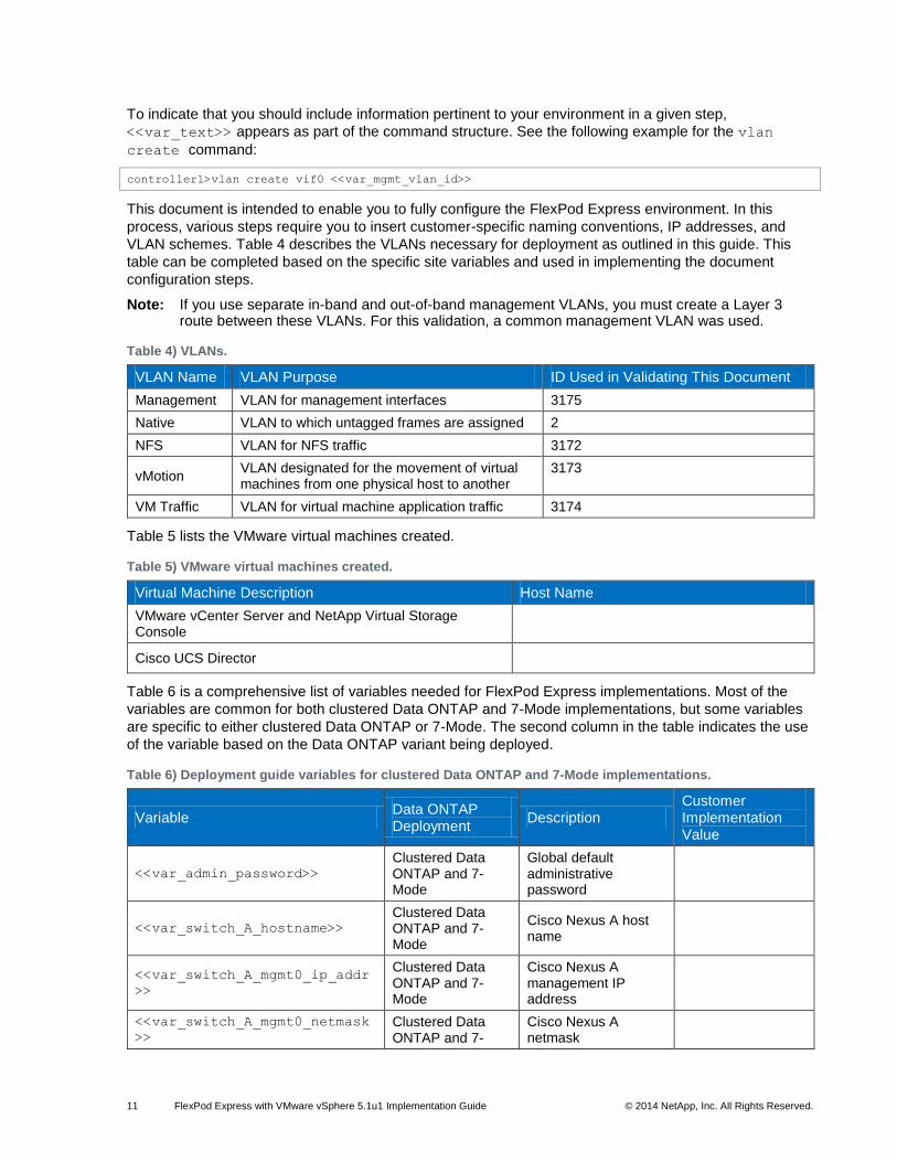
This document is intended to enable you to fully configure the FlexPod Express environment. In this
process, various steps require you to insert customer-specific naming conventions, IP addresses, and
VLAN schemes. Table 4 describes the VLANs necessary for deployment as outlined in this guide. This
table can be completed based on the specific site variables and used in implementing the document
configuration steps.
Note: If you use separate in-band and out-of-band management VLANs, you must create a Layer 3 route between these VLANs. For this validation, a common management VLAN was used.
Table 4) VLANs.
VLAN Name VLAN Purpose ID Used in Validating This Document
Management VLAN for management interfaces 3175
Native VLAN to which untagged frames are assigned 2
NFS VLAN for NFS traffic 3172
vMotion VLAN designated for the movement of virtual machines from one physical host to another
3173
VM Traffic VLAN for virtual machine application traffic 3174
Table 5 lists the VMware virtual machines created.
Table 5) VMware virtual machines created.
Virtual Machine Description Host Name
VMware vCenter Server and NetApp Virtual Storage Console
Cisco UCS Director
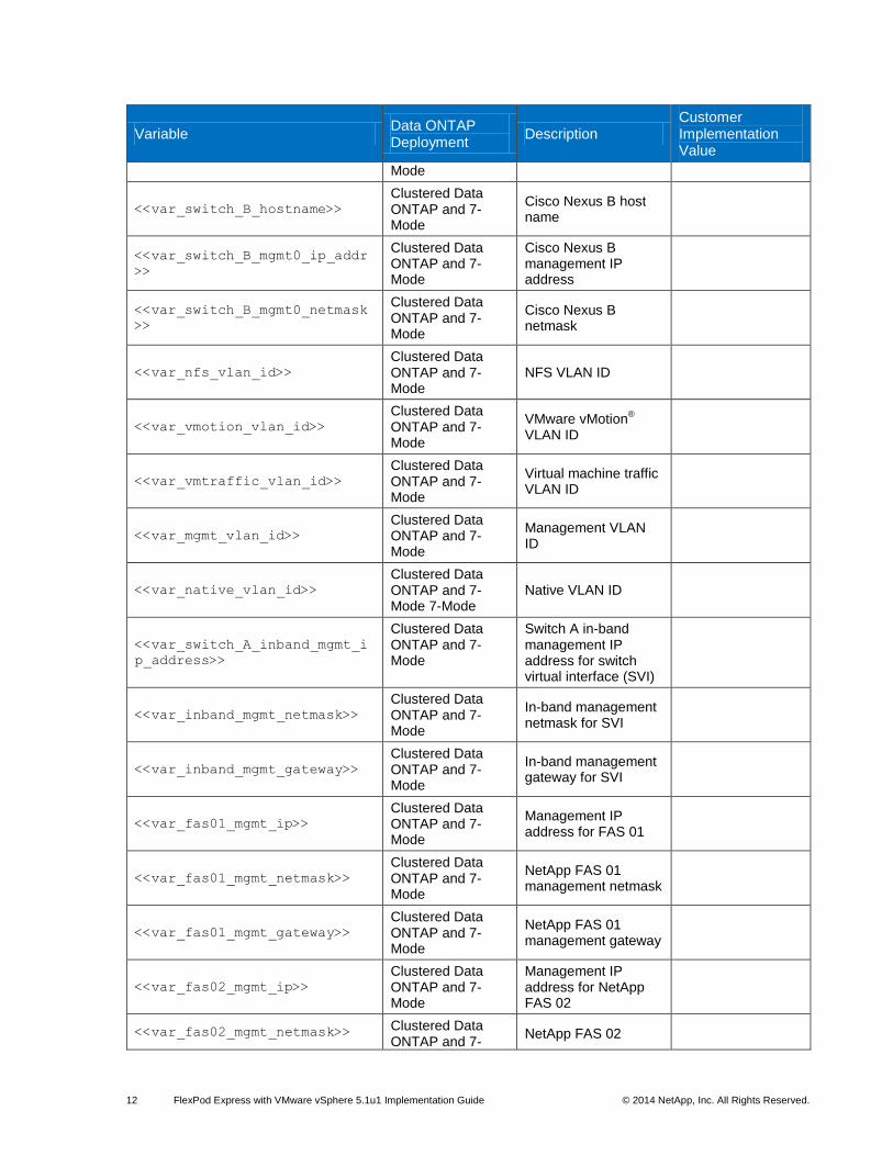
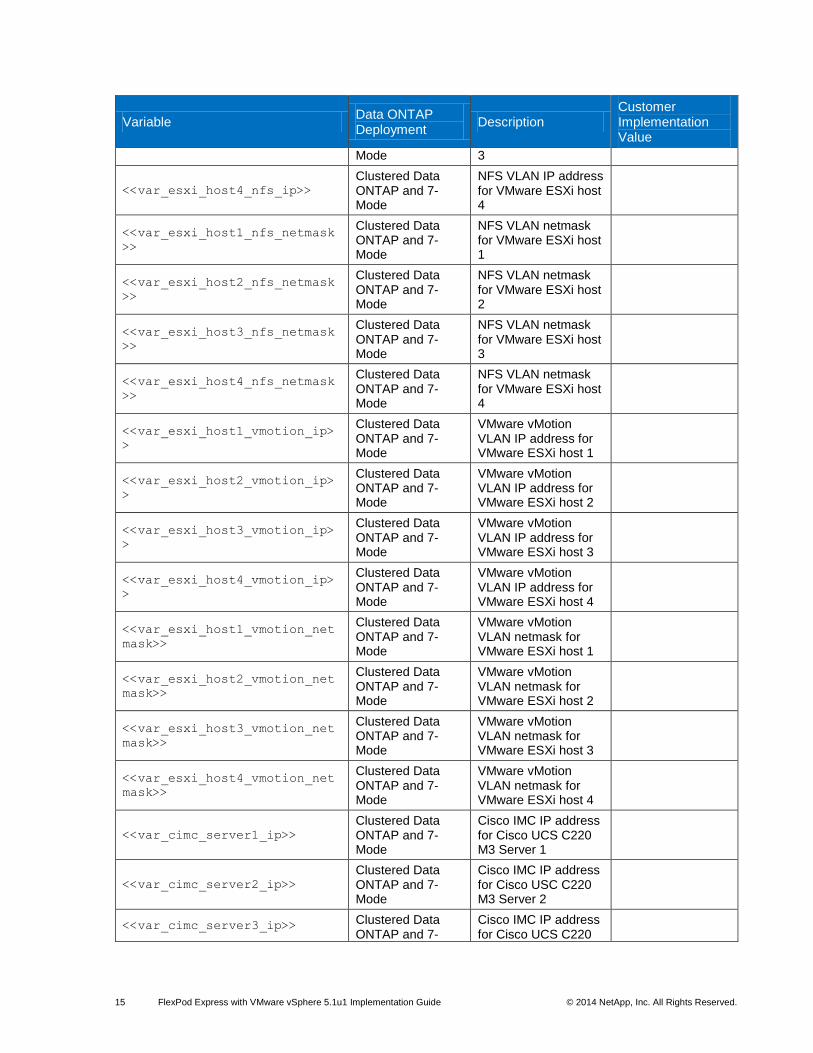
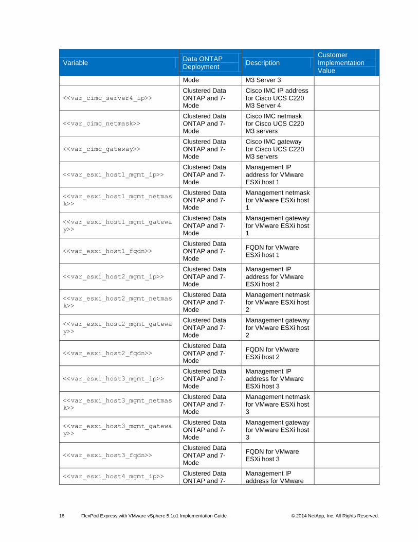
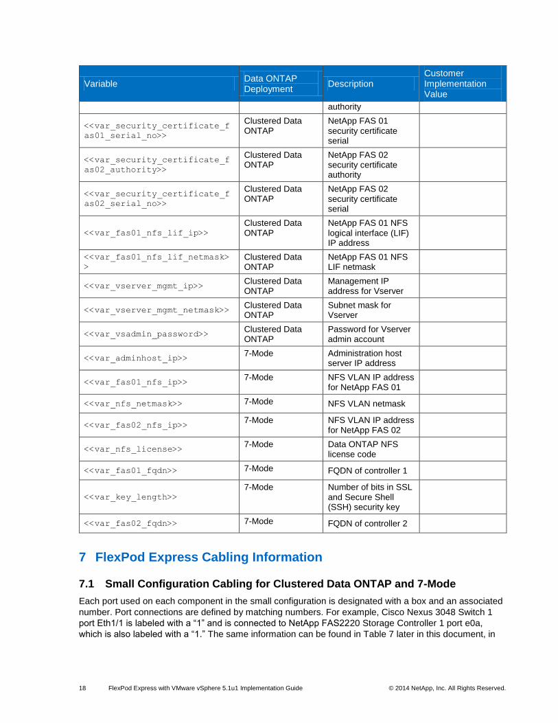
Table 6 is a comprehensive list of variables needed for FlexPod Express implementations. Most of the
variables are common for both clustered Data ONTAP and 7-Mode implementations, but some variables
are specific to either clustered Data ONTAP or 7-Mode. The second column in the table indicates the use
of the variable based on the Data ONTAP variant being deployed.
Table 6) Deployment guide variables for clustered Data ONTAP and 7-Mode implementations.
Variable Data ONTAP Deployment
Description Customer Implementation Value
<<var_admin_password>>
Clustered Data ONTAP and 7-Mode
Global default administrative password
<<var_switch_A_hostname>> Clustered Data ONTAP and 7-Mode
Cisco Nexus A host name
<<var_switch_A_mgmt0_ip_addr
>>
Clustered Data ONTAP and 7-Mode
Cisco Nexus A management IP address
<<var_switch_A_mgmt0_netmask
>>
Clustered Data ONTAP and 7-
Cisco Nexus A netmask
12 FlexPod Express with VMware vSphere 5.1u1 Implementation Guide © 2014 NetApp, Inc. All Rights Reserved.
Variable Data ONTAP Deployment
Description Customer Implementation Value
Mode
<<var_switch_B_hostname>>
Clustered Data ONTAP and 7-Mode
Cisco Nexus B host name
<<var_switch_B_mgmt0_ip_addr
>>
Clustered Data ONTAP and 7-Mode
Cisco Nexus B management IP address
<<var_switch_B_mgmt0_netmask
>>
Clustered Data ONTAP and 7-Mode
Cisco Nexus B netmask
<<var_nfs_vlan_id>>
Clustered Data ONTAP and 7-Mode
NFS VLAN ID
<<var_vmotion_vlan_id>>
Clustered Data ONTAP and 7-Mode
VMware vMotion®
VLAN ID
<<var_vmtraffic_vlan_id>>
Clustered Data ONTAP and 7-Mode
Virtual machine traffic VLAN ID
<<var_mgmt_vlan_id>>
Clustered Data ONTAP and 7-Mode
Management VLAN ID
<<var_native_vlan_id>>
Clustered Data ONTAP and 7-Mode 7-Mode
Native VLAN ID
<<var_switch_A_inband_mgmt_i
p_address>>
Clustered Data ONTAP and 7-Mode
Switch A in-band management IP address for switch virtual interface (SVI)
<<var_inband_mgmt_netmask>>
Clustered Data ONTAP and 7-Mode
In-band management netmask for SVI
<<var_inband_mgmt_gateway>>
Clustered Data ONTAP and 7-Mode
In-band management gateway for SVI
<<var_fas01_mgmt_ip>>
Clustered Data ONTAP and 7-Mode
Management IP address for FAS 01
<<var_fas01_mgmt_netmask>>
Clustered Data ONTAP and 7-Mode
NetApp FAS 01 management netmask
<<var_fas01_mgmt_gateway>>
Clustered Data ONTAP and 7-Mode
NetApp FAS 01 management gateway
<<var_fas02_mgmt_ip>>
Clustered Data ONTAP and 7-Mode
Management IP address for NetApp FAS 02
<<var_fas02_mgmt_netmask>> Clustered Data ONTAP and 7-
NetApp FAS 02
13 FlexPod Express with VMware vSphere 5.1u1 Implementation Guide © 2014 NetApp, Inc. All Rights Reserved.
Variable Data ONTAP Deployment
Description Customer Implementation Value
Mode management netmask
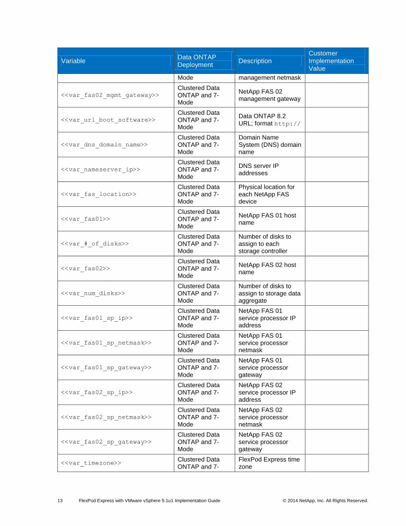
<<var_fas02_mgmt_gateway>>
Clustered Data ONTAP and 7-Mode
NetApp FAS 02 management gateway
<<var_url_boot_software>>
Clustered Data ONTAP and 7-Mode
Data ONTAP 8.2 URL; format http://
<<var_dns_domain_name>>
Clustered Data ONTAP and 7-Mode
Domain Name System (DNS) domain name
<<var_nameserver_ip>>
Clustered Data ONTAP and 7-Mode
DNS server IP addresses
<<var_fas_location>>
Clustered Data ONTAP and 7-Mode
Physical location for each NetApp FAS device
<<var_fas01>>
Clustered Data ONTAP and 7-Mode
NetApp FAS 01 host name
<<var_#_of_disks>>
Clustered Data ONTAP and 7-Mode
Number of disks to assign to each storage controller
<<var_fas02>>
Clustered Data ONTAP and 7-Mode
NetApp FAS 02 host name
<<var_num_disks>>
Clustered Data ONTAP and 7-Mode
Number of disks to assign to storage data aggregate
<<var_fas01_sp_ip>>
Clustered Data ONTAP and 7-Mode
NetApp FAS 01 service processor IP address
<<var_fas01_sp_netmask>>
Clustered Data ONTAP and 7-Mode
NetApp FAS 01 service processor netmask
<<var_fas01_sp_gateway>>
Clustered Data ONTAP and 7-Mode
NetApp FAS 01 service processor gateway
<<var_fas02_sp_ip>>
Clustered Data ONTAP and 7-Mode
NetApp FAS 02 service processor IP address
<<var_fas02_sp_netmask>>
Clustered Data ONTAP and 7-Mode
NetApp FAS 02 service processor netmask
<<var_fas02_sp_gateway>>
Clustered Data ONTAP and 7-Mode
NetApp FAS 02 service processor gateway
<<var_timezone>> Clustered Data ONTAP and 7-
FlexPod Express time zone
14 FlexPod Express with VMware vSphere 5.1u1 Implementation Guide © 2014 NetApp, Inc. All Rights Reserved.
Variable Data ONTAP Deployment
Description Customer Implementation Value
Mode
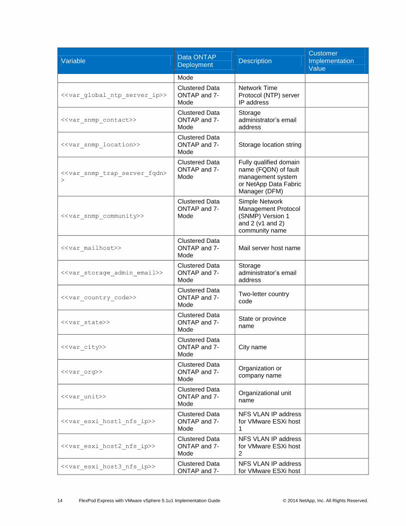
<<var_global_ntp_server_ip>>
Clustered Data ONTAP and 7-Mode
Network Time Protocol (NTP) server IP address
<<var_snmp_contact>>
Clustered Data ONTAP and 7-Mode
Storage administrator’s email address
<<var_snmp_location>>
Clustered Data ONTAP and 7-Mode
Storage location string
<<var_snmp_trap_server_fqdn>
>
Clustered Data ONTAP and 7-Mode
Fully qualified domain name (FQDN) of fault management system or NetApp Data Fabric Manager (DFM)
<<var_snmp_community>>
Clustered Data ONTAP and 7-Mode
Simple Network Management Protocol (SNMP) Version 1 and 2 (v1 and 2) community name
<<var_mailhost>>
Clustered Data ONTAP and 7-Mode
Mail server host name
<<var_storage_admin_email>>
Clustered Data ONTAP and 7-Mode
Storage administrator’s email address
<<var_country_code>>
Clustered Data ONTAP and 7-Mode
Two-letter country code
<<var_state>>
Clustered Data ONTAP and 7-Mode
State or province name
<<var_city>>
Clustered Data ONTAP and 7-Mode
City name
<<var_org>>
Clustered Data ONTAP and 7-Mode
Organization or company name
<<var_unit>>
Clustered Data ONTAP and 7-Mode
Organizational unit name
<<var_esxi_host1_nfs_ip>>
Clustered Data ONTAP and 7-Mode
NFS VLAN IP address for VMware ESXi host 1
<<var_esxi_host2_nfs_ip>>
Clustered Data ONTAP and 7-Mode
NFS VLAN IP address for VMware ESXi host 2
<<var_esxi_host3_nfs_ip>> Clustered Data ONTAP and 7-
NFS VLAN IP address for VMware ESXi host
15 FlexPod Express with VMware vSphere 5.1u1 Implementation Guide © 2014 NetApp, Inc. All Rights Reserved.
Variable Data ONTAP Deployment
Description Customer Implementation Value
Mode 3
<<var_esxi_host4_nfs_ip>>
Clustered Data ONTAP and 7-Mode
NFS VLAN IP address for VMware ESXi host 4
<<var_esxi_host1_nfs_netmask
>>
Clustered Data ONTAP and 7-Mode
NFS VLAN netmask for VMware ESXi host 1
<<var_esxi_host2_nfs_netmask
>>
Clustered Data ONTAP and 7-Mode
NFS VLAN netmask for VMware ESXi host 2
<<var_esxi_host3_nfs_netmask
>>
Clustered Data ONTAP and 7-Mode
NFS VLAN netmask for VMware ESXi host 3
<<var_esxi_host4_nfs_netmask
>>
Clustered Data ONTAP and 7-Mode
NFS VLAN netmask for VMware ESXi host 4
<<var_esxi_host1_vmotion_ip>
>
Clustered Data ONTAP and 7-Mode
VMware vMotion VLAN IP address for VMware ESXi host 1
<<var_esxi_host2_vmotion_ip>
>
Clustered Data ONTAP and 7-Mode
VMware vMotion VLAN IP address for VMware ESXi host 2
<<var_esxi_host3_vmotion_ip>
>
Clustered Data ONTAP and 7-Mode
VMware vMotion VLAN IP address for VMware ESXi host 3
<<var_esxi_host4_vmotion_ip>
>
Clustered Data ONTAP and 7-Mode
VMware vMotion VLAN IP address for VMware ESXi host 4
<<var_esxi_host1_vmotion_net
mask>>
Clustered Data ONTAP and 7-Mode
VMware vMotion VLAN netmask for VMware ESXi host 1
<<var_esxi_host2_vmotion_net
mask>>
Clustered Data ONTAP and 7-Mode
VMware vMotion VLAN netmask for VMware ESXi host 2
<<var_esxi_host3_vmotion_net
mask>>
Clustered Data ONTAP and 7-Mode
VMware vMotion VLAN netmask for VMware ESXi host 3
<<var_esxi_host4_vmotion_net
mask>>
Clustered Data ONTAP and 7-Mode
VMware vMotion VLAN netmask for VMware ESXi host 4
<<var_cimc_server1_ip>>
Clustered Data ONTAP and 7-Mode
Cisco IMC IP address for Cisco UCS C220 M3 Server 1
<<var_cimc_server2_ip>>
Clustered Data ONTAP and 7-Mode
Cisco IMC IP address for Cisco USC C220 M3 Server 2
<<var_cimc_server3_ip>> Clustered Data ONTAP and 7-
Cisco IMC IP address for Cisco UCS C220
16 FlexPod Express with VMware vSphere 5.1u1 Implementation Guide © 2014 NetApp, Inc. All Rights Reserved.
Variable Data ONTAP Deployment
Description Customer Implementation Value
Mode M3 Server 3
<<var_cimc_server4_ip>>
Clustered Data ONTAP and 7-Mode
Cisco IMC IP address for Cisco UCS C220 M3 Server 4
<<var_cimc_netmask>>
Clustered Data ONTAP and 7-Mode
Cisco IMC netmask for Cisco UCS C220 M3 servers
<<var_cimc_gateway>>
Clustered Data ONTAP and 7-Mode
Cisco IMC gateway for Cisco UCS C220 M3 servers
<<var_esxi_host1_mgmt_ip>> Clustered Data ONTAP and 7-Mode
Management IP address for VMware ESXi host 1
<<var_esxi_host1_mgmt_netmas
k>>
Clustered Data ONTAP and 7-Mode
Management netmask for VMware ESXi host 1
<<var_esxi_host1_mgmt_gatewa
y>>
Clustered Data ONTAP and 7-Mode
Management gateway for VMware ESXi host 1
<<var_esxi_host1_fqdn>> Clustered Data ONTAP and 7-Mode
FQDN for VMware ESXi host 1
<<var_esxi_host2_mgmt_ip>> Clustered Data ONTAP and 7-Mode
Management IP address for VMware ESXi host 2
<<var_esxi_host2_mgmt_netmas
k>>
Clustered Data ONTAP and 7-Mode
Management netmask for VMware ESXi host 2
<<var_esxi_host2_mgmt_gatewa
y>>
Clustered Data ONTAP and 7-Mode
Management gateway for VMware ESXi host 2
<<var_esxi_host2_fqdn>>
Clustered Data ONTAP and 7-Mode
FQDN for VMware ESXi host 2
<<var_esxi_host3_mgmt_ip>>
Clustered Data ONTAP and 7-Mode
Management IP address for VMware ESXi host 3
<<var_esxi_host3_mgmt_netmas
k>>
Clustered Data ONTAP and 7-Mode
Management netmask for VMware ESXi host 3
<<var_esxi_host3_mgmt_gatewa
y>>
Clustered Data ONTAP and 7-Mode
Management gateway for VMware ESXi host 3
<<var_esxi_host3_fqdn>>
Clustered Data ONTAP and 7-Mode
FQDN for VMware ESXi host 3
<<var_esxi_host4_mgmt_ip>> Clustered Data ONTAP and 7-
Management IP address for VMware

17 FlexPod Express with VMware vSphere 5.1u1 Implementation Guide © 2014 NetApp, Inc. All Rights Reserved.
Variable Data ONTAP Deployment
Description Customer Implementation Value
Mode ESXi host 4
<<var_esxi_host4_mgmt_netmas
k>>
Clustered Data ONTAP and 7-Mode
Management netmask for VMware ESXi host 4
<<var_esxi_host4_mgmt_gatewa
y>>
Clustered Data ONTAP and 7-Mode
Management gateway for VMware ESXi host 4
<<var_esxi_host4_fqdn>>
Clustered Data ONTAP and 7-Mode
FQDN for VMware ESXi host 4
<<var_clustername>> Clustered Data ONTAP
Storage cluster host name
<<var_cluster_base_license_k
ey>>
Clustered Data ONTAP
Cluster base license key
<<var_clustermgmt_ip>>
Clustered Data ONTAP
Cluster management IP address for the storage cluster
<<var_clustermgmt_netmask>>
Clustered Data ONTAP
Cluster management netmask for the storage cluster
<<var_clustermgmt_gateway>>
Clustered Data ONTAP
Cluster management gateway for the storage cluster
<<var_fas01_rootaggrname>> Clustered Data ONTAP
Root aggregate name of NetApp FAS 01
<<var_security_cert_vserver_
common_name>>
Clustered Data ONTAP
Infrastructure virtual server (Vserver) FQDN
<<var_security_cert_cluster_
common_name>>
Clustered Data ONTAP
Storage cluster FQDN
<<var_security_cert_fas01_co
mmon_name>>
Clustered Data ONTAP
NetApp FAS 01 FQDN
<<var_security_cert_fas02_co
mmon_name>>
Clustered Data ONTAP
NetApp FAS 02 FQDN
<<var_security_certificate_v
servser_authority>>
Clustered Data ONTAP
Infrastructure Vserver security certificate authority
<<var_security_certificate_v
server_serial_no>>
Clustered Data ONTAP
Infrastructure Vserver security certificate serial number
<<var_security_certificate_c
luster_authority>>
Clustered Data ONTAP
Storage cluster security certificate authority
<<var_security_certificate_c
luster_serial_no>>
Clustered Data ONTAP
Storage cluster security certificate serial number
<<var_security_certificate_f
as01_authority>>
Clustered Data ONTAP
NetApp FAS 01 security certificate
18 FlexPod Express with VMware vSphere 5.1u1 Implementation Guide © 2014 NetApp, Inc. All Rights Reserved.
Variable Data ONTAP Deployment
Description Customer Implementation Value
authority
<<var_security_certificate_f
as01_serial_no>>
Clustered Data ONTAP
NetApp FAS 01 security certificate serial
<<var_security_certificate_f
as02_authority>>
Clustered Data ONTAP
NetApp FAS 02 security certificate authority
<<var_security_certificate_f
as02_serial_no>>
Clustered Data ONTAP
NetApp FAS 02 security certificate serial
<<var_fas01_nfs_lif_ip>>
Clustered Data ONTAP
NetApp FAS 01 NFS logical interface (LIF) IP address
<<var_fas01_nfs_lif_netmask>
>
Clustered Data ONTAP
NetApp FAS 01 NFS LIF netmask
<<var_vserver_mgmt_ip>> Clustered Data ONTAP
Management IP address for Vserver
<<var_vserver_mgmt_netmask>> Clustered Data ONTAP
Subnet mask for Vserver
<<var_vsadmin_password>> Clustered Data ONTAP
Password for Vserver admin account
<<var_adminhost_ip>> 7-Mode Administration host
server IP address
<<var_fas01_nfs_ip>> 7-Mode NFS VLAN IP address
for NetApp FAS 01
<<var_nfs_netmask>> 7-Mode NFS VLAN netmask
<<var_fas02_nfs_ip>> 7-Mode NFS VLAN IP address
for NetApp FAS 02
<<var_nfs_license>> 7-Mode Data ONTAP NFS
license code
<<var_fas01_fqdn>> 7-Mode FQDN of controller 1
<<var_key_length>>
7-Mode Number of bits in SSL and Secure Shell (SSH) security key
<<var_fas02_fqdn>> 7-Mode FQDN of controller 2
7 FlexPod Express Cabling Information
7.1 Small Configuration Cabling for Clustered Data ONTAP and 7-Mode
Each port used on each component in the small configuration is designated with a box and an associated
number. Port connections are defined by matching numbers. For example, Cisco Nexus 3048 Switch 1
port Eth1/1 is labeled with a “1” and is connected to NetApp FAS2220 Storage Controller 1 port e0a,
which is also labeled with a “1.” The same information can be found in Table 7 later in this document, in

19 FlexPod Express with VMware vSphere 5.1u1 Implementation Guide © 2014 NetApp, Inc. All Rights Reserved.
the Cabling Code column. Figure 3 and Figure 4 show the cabling diagrams for clustered Data ONTAP
and 7-Mode, respectively.
Figure 3) Clustered Data ONTAP cabling diagram.
Figure 4) Data ONTAP 7-Mode cabling diagram.
Small Configuration Cabling Details for Clustered Data ONTAP and 7-Mode
Tables 7 through 10 detail the cabling connections for the small FlexPod Express configurations shown in
Figure 3 and Figure 4.

20 FlexPod Express with VMware vSphere 5.1u1 Implementation Guide © 2014 NetApp, Inc. All Rights Reserved.
Table 7) Cisco Nexus 3048 switch 1.
Local Device Local Port Remote Device Remote
Port
Cabling
Code
Cisco Nexus 3048 Switch 1
Eth1/1 NetApp FAS2220 Storage Controller 1 e0a
Eth1/2 NetApp FAS2220 Storage Controller 2 e0a
Eth1/3 NetApp FAS2220 Storage Controller 1 e0c
Eth1/4 NetApp FAS2220 Storage Controller 2 e0c
Eth1/13 Cisco UCS C220 M3 Standalone Server 1 e1a
Eth1/14 Cisco UCS C220 M3 Standalone Server 1 e1b
Eth1/15 Cisco UCS C220 M3 Standalone Server 2 e1a
Eth1/16 Cisco UCS C220 M3 Standalone Server 2 e1b
Eth1/25 Cisco Nexus 3048 Switch 2 Eth1/25
Eth1/26 Cisco Nexus 3048 Switch 2 Eth1/26
Eth1/37 Cisco UCS C220 M3 Standalone Server 1 Management port
Eth1/39 NetApp FAS2220 Storage Controller 1 Management port
Table 8) Cisco Nexus 3048 switch 2.
Local Device Local Port Remote Device Remote
Port
Cabling
Code
Cisco Nexus 3048 Switch 2
Eth1/1 NetApp FAS2220 Storage Controller 1 e0b
Eth1/2 NetApp FAS2220 Storage Controller 2 e0b
Eth1/3 NetApp FAS2220 Storage Controller 1 e0d
Eth1/4 NetApp FAS2220 Storage Controller 2 e0d
Eth1/13 Cisco UCS C220 M3 Standalone Server 1 e1c
Eth1/14 Cisco UCS C220 M3 Standalone Server 1 e1d
1
2
3
4
5
6
7
8
9
10
11
12
13
14
15
16
17
18
21 FlexPod Express with VMware vSphere 5.1u1 Implementation Guide © 2014 NetApp, Inc. All Rights Reserved.
Local Device Local Port Remote Device Remote
Port
Cabling
Code
Eth1/15 Cisco UCS C220 M3 Standalone Server 2 e1c
Eth1/16 Cisco UCS C220 M3 Standalone Server 2 e1d
Eth1/25 Cisco Nexus 3048 Switch 1 Eth1/25
Eth1/26 Cisco Nexus 3048 Switch 1 Eth1/26
Eth1/37 Cisco UCS C220 M3 Standalone Server 2 Management port
Eth1/39 NetApp FAS2220 Storage Controller 2 Management port
Table 9) NetApp storage controller 1 (clustered Data ONTAP only).
Local Device Local Port Remote Device Remote
Port
Cabling
Code
NetApp Storage Controller 1
e1a NetApp FAS2220 Storage Controller 2 e1a
e1b NetApp FAS2220 Storage Controller 2 e1b
Table 10) NetApp storage controller 2 (clustered Data ONTAP only).
Local Device Local Port Remote Device Remote
Port
Cabling
Code
NetApp Storage Controller 2
e1a NetApp FAS2220 Storage Controller 1 e1a
e1b NetApp FAS2220 Storage Controller 1 e1b
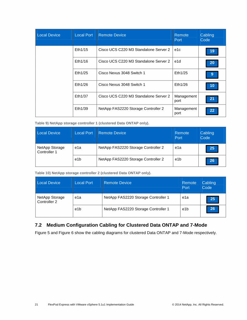
7.2 Medium Configuration Cabling for Clustered Data ONTAP and 7-Mode
Figure 5 and Figure 6 show the cabling diagrams for clustered Data ONTAP and 7-Mode respectively.
19
20
9
10
21
22
25
26
25
26

22 FlexPod Express with VMware vSphere 5.1u1 Implementation Guide © 2014 NetApp, Inc. All Rights Reserved.
Figure 5) Clustered Data ONTAP cabling diagram.

23 FlexPod Express with VMware vSphere 5.1u1 Implementation Guide © 2014 NetApp, Inc. All Rights Reserved.
Figure 6) Data ONTAP 7-Mode cabling diagram.
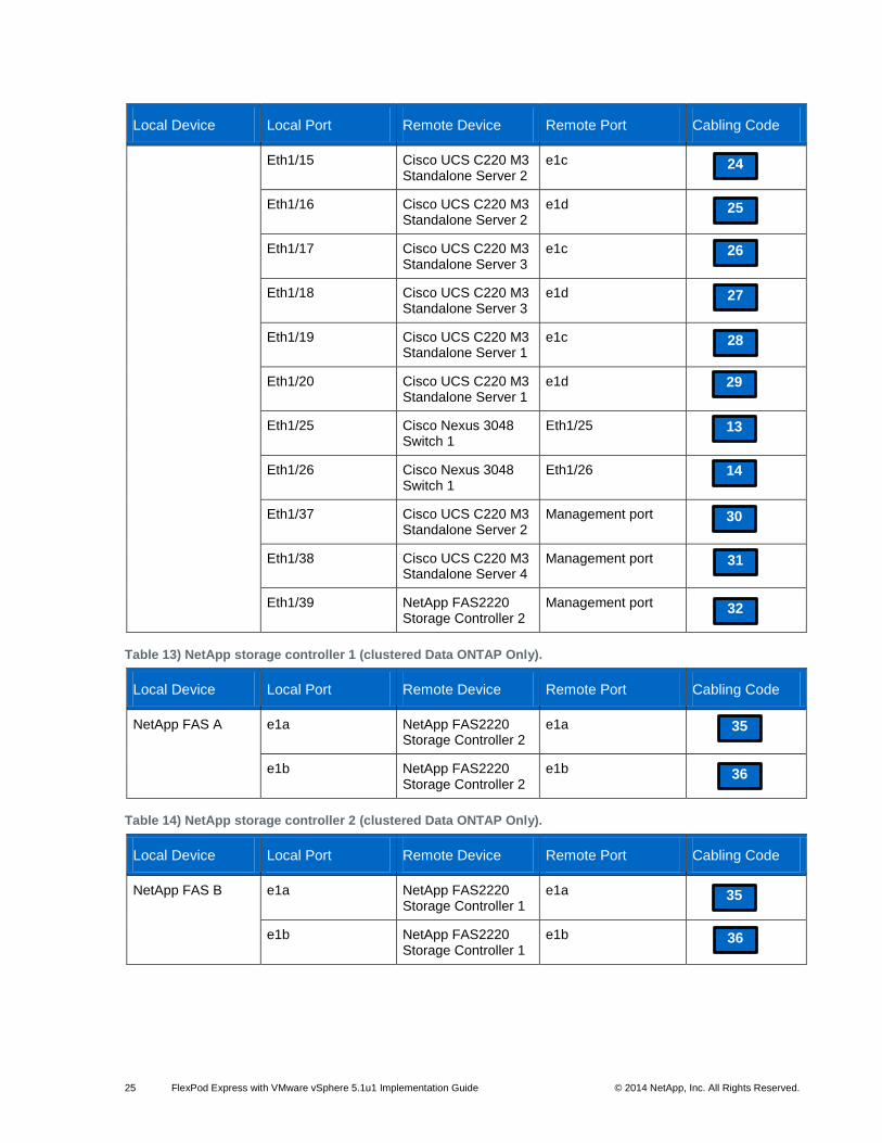
Medium Configuration Cabling Details for Clustered Data ONTAP and 7-Mode
Tables 11 through 14 detail the cabling connections for the medium FlexPod Express configurations
shown in Figure 5 and Figure 6.
Table 11) Cisco Nexus 3048 A cabling information.
Local Device Local Port Remote Device Remote Port Cabling Code
Cisco Nexus 3048 Switch 1
Eth1/1 NetApp FAS2220 Storage Controller 1
e0a
Eth1/2 NetApp FAS2220 Storage Controller 2
e0a
Eth1/3 NetApp FAS2220 Storage Controller 1
e0c
Eth1/4 NetApp FAS2220 Storage Controller 2
e0c
Eth1/13 Cisco UCS C220 M3 Standalone Server 1
e1a
1
2
3
4
5

24 FlexPod Express with VMware vSphere 5.1u1 Implementation Guide © 2014 NetApp, Inc. All Rights Reserved.
Local Device Local Port Remote Device Remote Port Cabling Code
Eth1/14 Cisco UCS C220 M3 Standalone Server 1
e1b
Eth1/15 Cisco UCS C220 M3 Standalone Server 2
e1a
Eth1/16 Cisco UCS C220 M3 Standalone Server 2
e1b
Eth1/17 Cisco UCS C220 M3 Standalone Server 3
e1a
Eth1/18 Cisco UCS C220 M3 Standalone Server 3
e1b
Eth1/19 Cisco UCS C220 M3 Standalone Server 1
e1a
Eth1/20 Cisco UCS C220 M3 Standalone Server 1
e1b
Eth1/25 Cisco Nexus 3048 Switch 2
Eth1/25
Eth1/26 Cisco Nexus 3048 Switch 2
Eth1/26
Eth1/37 Cisco UCS C220 M3 Standalone Server 1
Management port
Eth1/38 Cisco UCS C220 M3 Standalone Server 3
Management port
Eth1/39 NetApp FAS2220 Storage Controller 1
Management port
Table 12) Cisco Nexus 3048 B cabling information.
Local Device Local Port Remote Device Remote Port Cabling Code
Cisco Nexus 3048 Switch 2
Eth1/1 NetApp FAS2220 Storage Controller 1
e0b
Eth1/2 NetApp FAS2220 Storage Controller 2
e0b
Eth1/3 NetApp FAS2220 Storage Controller 1
e0d
Eth1/4 NetApp FAS2220 Storage Controller 2
e0d
Eth1/13 Cisco UCS C220 M3 Standalone Server 1
e1c
Eth1/14 Cisco UCS C220 M3 Standalone Server 1
e1d
6
7
8
9
10
11
12
13
14
15
16
17
18
19
20
21
22
23
25 FlexPod Express with VMware vSphere 5.1u1 Implementation Guide © 2014 NetApp, Inc. All Rights Reserved.
Local Device Local Port Remote Device Remote Port Cabling Code
Eth1/15 Cisco UCS C220 M3 Standalone Server 2
e1c
Eth1/16 Cisco UCS C220 M3 Standalone Server 2
e1d
Eth1/17 Cisco UCS C220 M3 Standalone Server 3
e1c
Eth1/18 Cisco UCS C220 M3 Standalone Server 3
e1d
Eth1/19 Cisco UCS C220 M3 Standalone Server 1
e1c
Eth1/20 Cisco UCS C220 M3 Standalone Server 1
e1d
Eth1/25 Cisco Nexus 3048 Switch 1
Eth1/25
Eth1/26 Cisco Nexus 3048 Switch 1
Eth1/26
Eth1/37 Cisco UCS C220 M3 Standalone Server 2
Management port
Eth1/38 Cisco UCS C220 M3 Standalone Server 4
Management port
Eth1/39 NetApp FAS2220 Storage Controller 2
Management port
Table 13) NetApp storage controller 1 (clustered Data ONTAP Only).
Local Device Local Port Remote Device Remote Port Cabling Code
NetApp FAS A e1a NetApp FAS2220 Storage Controller 2
e1a
e1b NetApp FAS2220 Storage Controller 2
e1b
Table 14) NetApp storage controller 2 (clustered Data ONTAP Only).
Local Device Local Port Remote Device Remote Port Cabling Code
NetApp FAS B e1a NetApp FAS2220 Storage Controller 1
e1a
e1b NetApp FAS2220 Storage Controller 1
e1b
24
25
26
27
28
29
13
14
30
31
32
35
36
35
36
26 FlexPod Express with VMware vSphere 5.1u1 Implementation Guide © 2014 NetApp, Inc. All Rights Reserved.
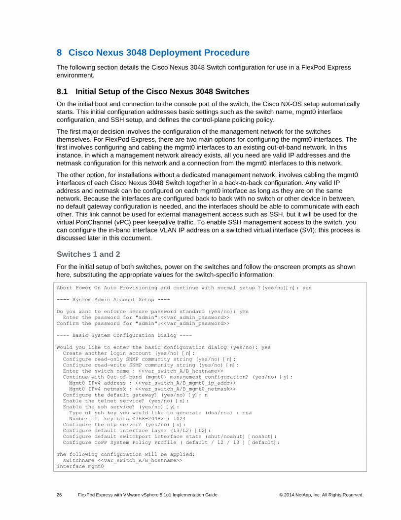
8 Cisco Nexus 3048 Deployment Procedure
The following section details the Cisco Nexus 3048 Switch configuration for use in a FlexPod Express
environment.
8.1 Initial Setup of the Cisco Nexus 3048 Switches
On the initial boot and connection to the console port of the switch, the Cisco NX-OS setup automatically
starts. This initial configuration addresses basic settings such as the switch name, mgmt0 interface
configuration, and SSH setup, and defines the control-plane policing policy.
The first major decision involves the configuration of the management network for the switches
themselves. For FlexPod Express, there are two main options for configuring the mgmt0 interfaces. The
first involves configuring and cabling the mgmt0 interfaces to an existing out-of-band network. In this
instance, in which a management network already exists, all you need are valid IP addresses and the
netmask configuration for this network and a connection from the mgmt0 interfaces to this network.
The other option, for installations without a dedicated management network, involves cabling the mgmt0
interfaces of each Cisco Nexus 3048 Switch together in a back-to-back configuration. Any valid IP
address and netmask can be configured on each mgmt0 interface as long as they are on the same
network. Because the interfaces are configured back to back with no switch or other device in between,
no default gateway configuration is needed, and the interfaces should be able to communicate with each
other. This link cannot be used for external management access such as SSH, but it will be used for the
virtual PortChannel (vPC) peer keepalive traffic. To enable SSH management access to the switch, you
can configure the in-band interface VLAN IP address on a switched virtual interface (SVI); this process is
discussed later in this document.
Switches 1 and 2
For the initial setup of both switches, power on the switches and follow the onscreen prompts as shown
here, substituting the appropriate values for the switch-specific information:
Abort Power On Auto Provisioning and continue with normal setup ?(yes/no)[n]: yes
---- System Admin Account Setup ----
Do you want to enforce secure password standard (yes/no): yes
Enter the password for "admin":<<var_admin_password>>
Confirm the password for "admin":<<var_admin_password>>
---- Basic System Configuration Dialog ----
Would you like to enter the basic configuration dialog (yes/no): yes
Create another login account (yes/no) [n]:
Configure read-only SNMP community string (yes/no) [n]:
Configure read-write SNMP community string (yes/no) [n]:
Enter the switch name : <<var_switch_A/B_hostname>>
Continue with Out-of-band (mgmt0) management configuration? (yes/no) [y]:
Mgmt0 IPv4 address : <<var_switch_A/B_mgmt0_ip_addr>>
Mgmt0 IPv4 netmask : <<var_switch_A/B_mgmt0_netmask>>
Configure the default gateway? (yes/no) [y]: n
Enable the telnet service? (yes/no) [n]:
Enable the ssh service? (yes/no) [y]:
Type of ssh key you would like to generate (dsa/rsa) : rsa
Number of key bits <768-2048> : 1024
Configure the ntp server? (yes/no) [n]:
Configure default interface layer (L3/L2) [L2]:
Configure default switchport interface state (shut/noshut) [noshut]:
Configure CoPP System Policy Profile ( default / l2 / l3 ) [default]:
The following configuration will be applied:
switchname <<var_switch_A/B_hostname>>
interface mgmt0
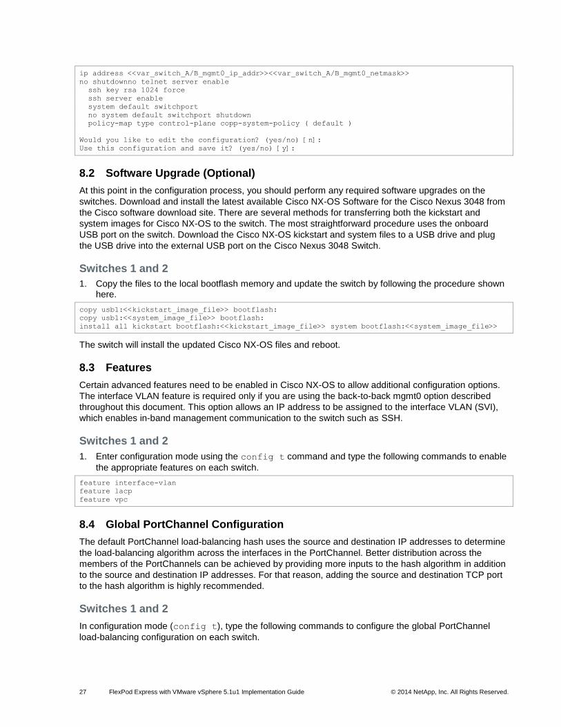
27 FlexPod Express with VMware vSphere 5.1u1 Implementation Guide © 2014 NetApp, Inc. All Rights Reserved.
ip address <<var_switch_A/B_mgmt0_ip_addr>><<var_switch_A/B_mgmt0_netmask>>
no shutdownno telnet server enable
ssh key rsa 1024 force
ssh server enable
system default switchport
no system default switchport shutdown
policy-map type control-plane copp-system-policy ( default )
Would you like to edit the configuration? (yes/no) [n]:
Use this configuration and save it? (yes/no) [y]:
8.2 Software Upgrade (Optional)
At this point in the configuration process, you should perform any required software upgrades on the
switches. Download and install the latest available Cisco NX-OS Software for the Cisco Nexus 3048 from
the Cisco software download site. There are several methods for transferring both the kickstart and
system images for Cisco NX-OS to the switch. The most straightforward procedure uses the onboard
USB port on the switch. Download the Cisco NX-OS kickstart and system files to a USB drive and plug
the USB drive into the external USB port on the Cisco Nexus 3048 Switch.
Switches 1 and 2
1. Copy the files to the local bootflash memory and update the switch by following the procedure shown here.
copy usb1:<<kickstart_image_file>> bootflash:
copy usb1:<<system_image_file>> bootflash:
install all kickstart bootflash:<<kickstart_image_file>> system bootflash:<<system_image_file>>
The switch will install the updated Cisco NX-OS files and reboot.
8.3 Features
Certain advanced features need to be enabled in Cisco NX-OS to allow additional configuration options.
The interface VLAN feature is required only if you are using the back-to-back mgmt0 option described
throughout this document. This option allows an IP address to be assigned to the interface VLAN (SVI),
which enables in-band management communication to the switch such as SSH.
Switches 1 and 2
1. Enter configuration mode using the config t command and type the following commands to enable
the appropriate features on each switch.
feature interface-vlan
feature lacp
feature vpc
8.4 Global PortChannel Configuration
The default PortChannel load-balancing hash uses the source and destination IP addresses to determine
the load-balancing algorithm across the interfaces in the PortChannel. Better distribution across the
members of the PortChannels can be achieved by providing more inputs to the hash algorithm in addition
to the source and destination IP addresses. For that reason, adding the source and destination TCP port
to the hash algorithm is highly recommended.
Switches 1 and 2
In configuration mode (config t), type the following commands to configure the global PortChannel
load-balancing configuration on each switch.
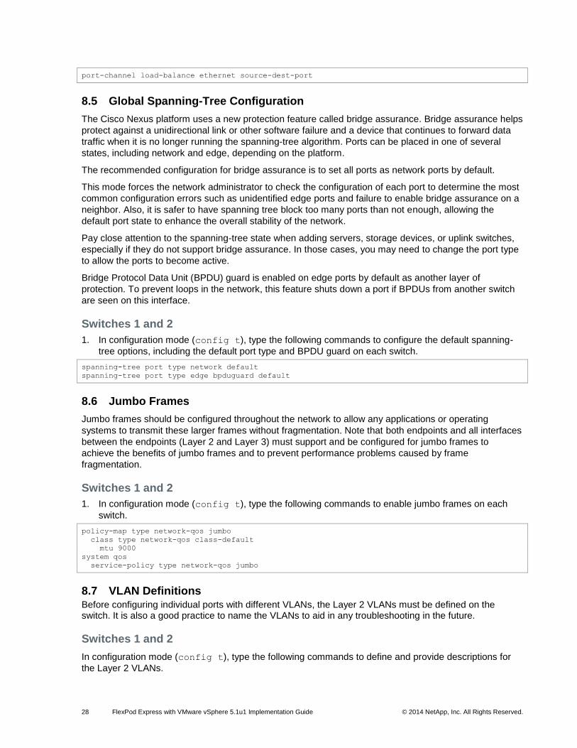
28 FlexPod Express with VMware vSphere 5.1u1 Implementation Guide © 2014 NetApp, Inc. All Rights Reserved.
port-channel load-balance ethernet source-dest-port
8.5 Global Spanning-Tree Configuration
The Cisco Nexus platform uses a new protection feature called bridge assurance. Bridge assurance helps
protect against a unidirectional link or other software failure and a device that continues to forward data
traffic when it is no longer running the spanning-tree algorithm. Ports can be placed in one of several
states, including network and edge, depending on the platform.
The recommended configuration for bridge assurance is to set all ports as network ports by default.
This mode forces the network administrator to check the configuration of each port to determine the most
common configuration errors such as unidentified edge ports and failure to enable bridge assurance on a
neighbor. Also, it is safer to have spanning tree block too many ports than not enough, allowing the
default port state to enhance the overall stability of the network.
Pay close attention to the spanning-tree state when adding servers, storage devices, or uplink switches,
especially if they do not support bridge assurance. In those cases, you may need to change the port type
to allow the ports to become active.
Bridge Protocol Data Unit (BPDU) guard is enabled on edge ports by default as another layer of
protection. To prevent loops in the network, this feature shuts down a port if BPDUs from another switch
are seen on this interface.
Switches 1 and 2
1. In configuration mode (config t), type the following commands to configure the default spanning-
tree options, including the default port type and BPDU guard on each switch.
spanning-tree port type network default
spanning-tree port type edge bpduguard default
8.6 Jumbo Frames
Jumbo frames should be configured throughout the network to allow any applications or operating
systems to transmit these larger frames without fragmentation. Note that both endpoints and all interfaces
between the endpoints (Layer 2 and Layer 3) must support and be configured for jumbo frames to
achieve the benefits of jumbo frames and to prevent performance problems caused by frame
fragmentation.
Switches 1 and 2
1. In configuration mode (config t), type the following commands to enable jumbo frames on each
switch.
policy-map type network-qos jumbo
class type network-qos class-default
mtu 9000
system qos
service-policy type network-qos jumbo
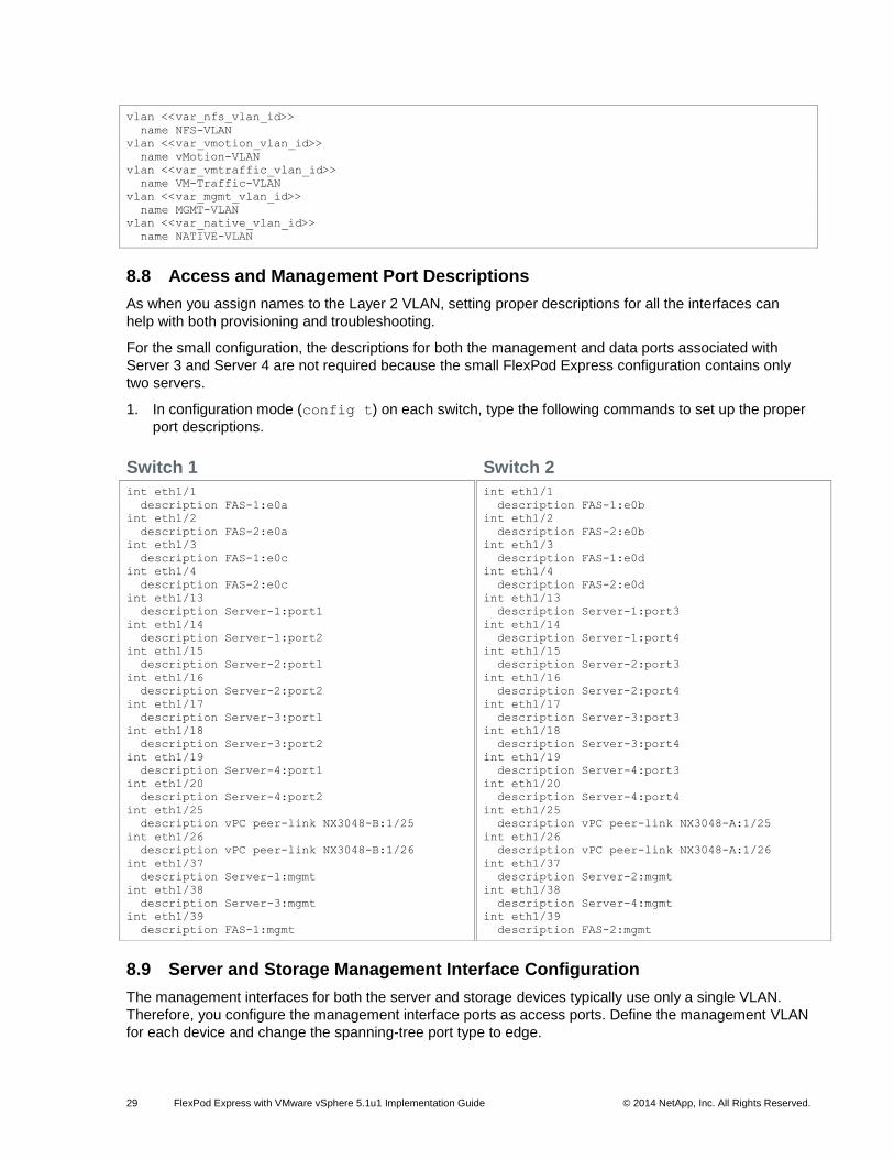
8.7 VLAN Definitions Before configuring individual ports with different VLANs, the Layer 2 VLANs must be defined on the switch. It is also a good practice to name the VLANs to aid in any troubleshooting in the future.
Switches 1 and 2
In configuration mode (config t), type the following commands to define and provide descriptions for
the Layer 2 VLANs.
29 FlexPod Express with VMware vSphere 5.1u1 Implementation Guide © 2014 NetApp, Inc. All Rights Reserved.
vlan <<var_nfs_vlan_id>>
name NFS-VLAN
vlan <<var_vmotion_vlan_id>>
name vMotion-VLAN
vlan <<var_vmtraffic_vlan_id>>
name VM-Traffic-VLAN
vlan <<var_mgmt_vlan_id>>
name MGMT-VLAN
vlan <<var_native_vlan_id>>
name NATIVE-VLAN
8.8 Access and Management Port Descriptions
As when you assign names to the Layer 2 VLAN, setting proper descriptions for all the interfaces can
help with both provisioning and troubleshooting.
For the small configuration, the descriptions for both the management and data ports associated with
Server 3 and Server 4 are not required because the small FlexPod Express configuration contains only
two servers.
1. In configuration mode (config t) on each switch, type the following commands to set up the proper
port descriptions.
Switch 1
int eth1/1
description FAS-1:e0a
int eth1/2
description FAS-2:e0a
int eth1/3
description FAS-1:e0c
int eth1/4
description FAS-2:e0c
int eth1/13
description Server-1:port1
int eth1/14
description Server-1:port2
int eth1/15
description Server-2:port1
int eth1/16
description Server-2:port2
int eth1/17
description Server-3:port1
int eth1/18
description Server-3:port2
int eth1/19
description Server-4:port1
int eth1/20
description Server-4:port2
int eth1/25
description vPC peer-link NX3048-B:1/25
int eth1/26
description vPC peer-link NX3048-B:1/26
int eth1/37
description Server-1:mgmt
int eth1/38
description Server-3:mgmt
int eth1/39
description FAS-1:mgmt
Switch 2
int eth1/1
description FAS-1:e0b
int eth1/2
description FAS-2:e0b
int eth1/3
description FAS-1:e0d
int eth1/4
description FAS-2:e0d
int eth1/13
description Server-1:port3
int eth1/14
description Server-1:port4
int eth1/15
description Server-2:port3
int eth1/16
description Server-2:port4
int eth1/17
description Server-3:port3
int eth1/18
description Server-3:port4
int eth1/19
description Server-4:port3
int eth1/20
description Server-4:port4
int eth1/25
description vPC peer-link NX3048-A:1/25
int eth1/26
description vPC peer-link NX3048-A:1/26
int eth1/37
description Server-2:mgmt
int eth1/38
description Server-4:mgmt
int eth1/39
description FAS-2:mgmt
8.9 Server and Storage Management Interface Configuration
The management interfaces for both the server and storage devices typically use only a single VLAN.
Therefore, you configure the management interface ports as access ports. Define the management VLAN
for each device and change the spanning-tree port type to edge.
30 FlexPod Express with VMware vSphere 5.1u1 Implementation Guide © 2014 NetApp, Inc. All Rights Reserved.
Switches 1 and 2
1. In configuration mode (config t), type the following commands to configure the port settings for the
management interfaces of both the servers and storage devices.
int eth1/37-39
switchport access vlan <<var_mgmt_vlan_id>>
spanning-tree port type edge
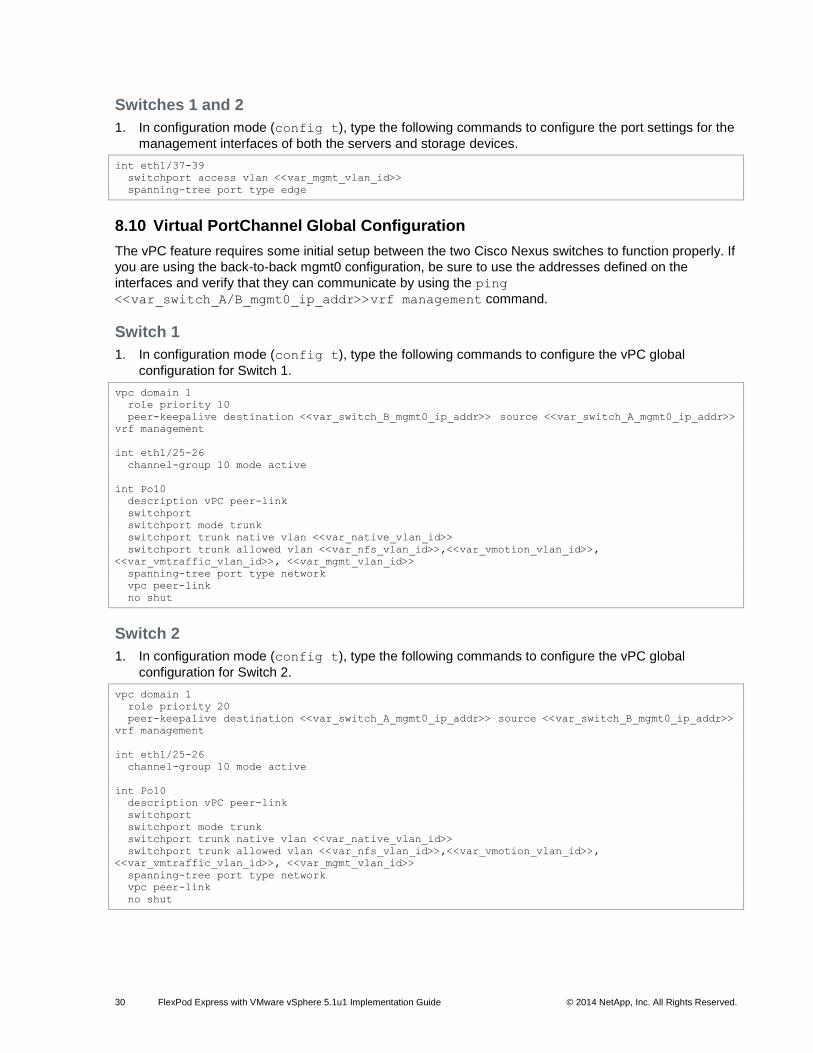
8.10 Virtual PortChannel Global Configuration
The vPC feature requires some initial setup between the two Cisco Nexus switches to function properly. If
you are using the back-to-back mgmt0 configuration, be sure to use the addresses defined on the
interfaces and verify that they can communicate by using the ping
<<var_switch_A/B_mgmt0_ip_addr>>vrf management command.
Switch 1
1. In configuration mode (config t), type the following commands to configure the vPC global
configuration for Switch 1.
vpc domain 1
role priority 10
peer-keepalive destination <<var_switch_B_mgmt0_ip_addr>> source <<var_switch_A_mgmt0_ip_addr>> vrf management
int eth1/25-26
channel-group 10 mode active
int Po10
description vPC peer-link
switchport
switchport mode trunk
switchport trunk native vlan <<var_native_vlan_id>>
switchport trunk allowed vlan <<var_nfs_vlan_id>>,<<var_vmotion_vlan_id>>,
<<var_vmtraffic_vlan_id>>, <<var_mgmt_vlan_id>>
spanning-tree port type network
vpc peer-link
no shut
Switch 2
1. In configuration mode (config t), type the following commands to configure the vPC global
configuration for Switch 2.
vpc domain 1
role priority 20
peer-keepalive destination <<var_switch_A_mgmt0_ip_addr>> source <<var_switch_B_mgmt0_ip_addr>>
vrf management
int eth1/25-26
channel-group 10 mode active
int Po10
description vPC peer-link
switchport
switchport mode trunk
switchport trunk native vlan <<var_native_vlan_id>>
switchport trunk allowed vlan <<var_nfs_vlan_id>>,<<var_vmotion_vlan_id>>,
<<var_vmtraffic_vlan_id>>, <<var_mgmt_vlan_id>>
spanning-tree port type network
vpc peer-link
no shut
31 FlexPod Express with VMware vSphere 5.1u1 Implementation Guide © 2014 NetApp, Inc. All Rights Reserved.
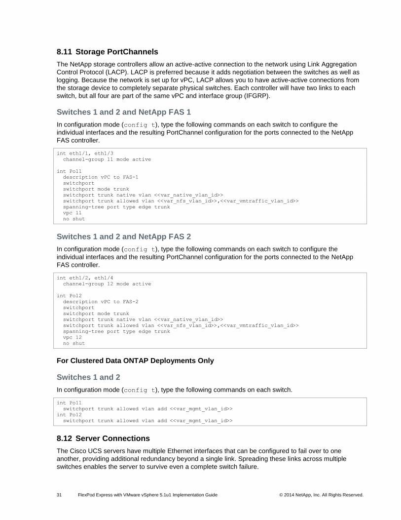
8.11 Storage PortChannels
The NetApp storage controllers allow an active-active connection to the network using Link Aggregation
Control Protocol (LACP). LACP is preferred because it adds negotiation between the switches as well as
logging. Because the network is set up for vPC, LACP allows you to have active-active connections from
the storage device to completely separate physical switches. Each controller will have two links to each
switch, but all four are part of the same vPC and interface group (IFGRP).
Switches 1 and 2 and NetApp FAS 1
In configuration mode (config t), type the following commands on each switch to configure the
individual interfaces and the resulting PortChannel configuration for the ports connected to the NetApp
FAS controller.
int eth1/1, eth1/3
channel-group 11 mode active
int Po11
description vPC to FAS-1
switchport
switchport mode trunk
switchport trunk native vlan <<var_native_vlan_id>>
switchport trunk allowed vlan <<var_nfs_vlan_id>>,<<var_vmtraffic_vlan_id>>
spanning-tree port type edge trunk
vpc 11
no shut
Switches 1 and 2 and NetApp FAS 2
In configuration mode (config t), type the following commands on each switch to configure the
individual interfaces and the resulting PortChannel configuration for the ports connected to the NetApp
FAS controller.
int eth1/2, eth1/4
channel-group 12 mode active
int Po12
description vPC to FAS-2
switchport
switchport mode trunk
switchport trunk native vlan <<var_native_vlan_id>>
switchport trunk allowed vlan <<var_nfs_vlan_id>>,<<var_vmtraffic_vlan_id>>
spanning-tree port type edge trunk
vpc 12
no shut
For Clustered Data ONTAP Deployments Only
Switches 1 and 2
In configuration mode (config t), type the following commands on each switch.
int Po11
switchport trunk allowed vlan add <<var_mgmt_vlan_id>>
int Po12
switchport trunk allowed vlan add <<var_mgmt_vlan_id>>
8.12 Server Connections
The Cisco UCS servers have multiple Ethernet interfaces that can be configured to fail over to one
another, providing additional redundancy beyond a single link. Spreading these links across multiple
switches enables the server to survive even a complete switch failure.
32 FlexPod Express with VMware vSphere 5.1u1 Implementation Guide © 2014 NetApp, Inc. All Rights Reserved.
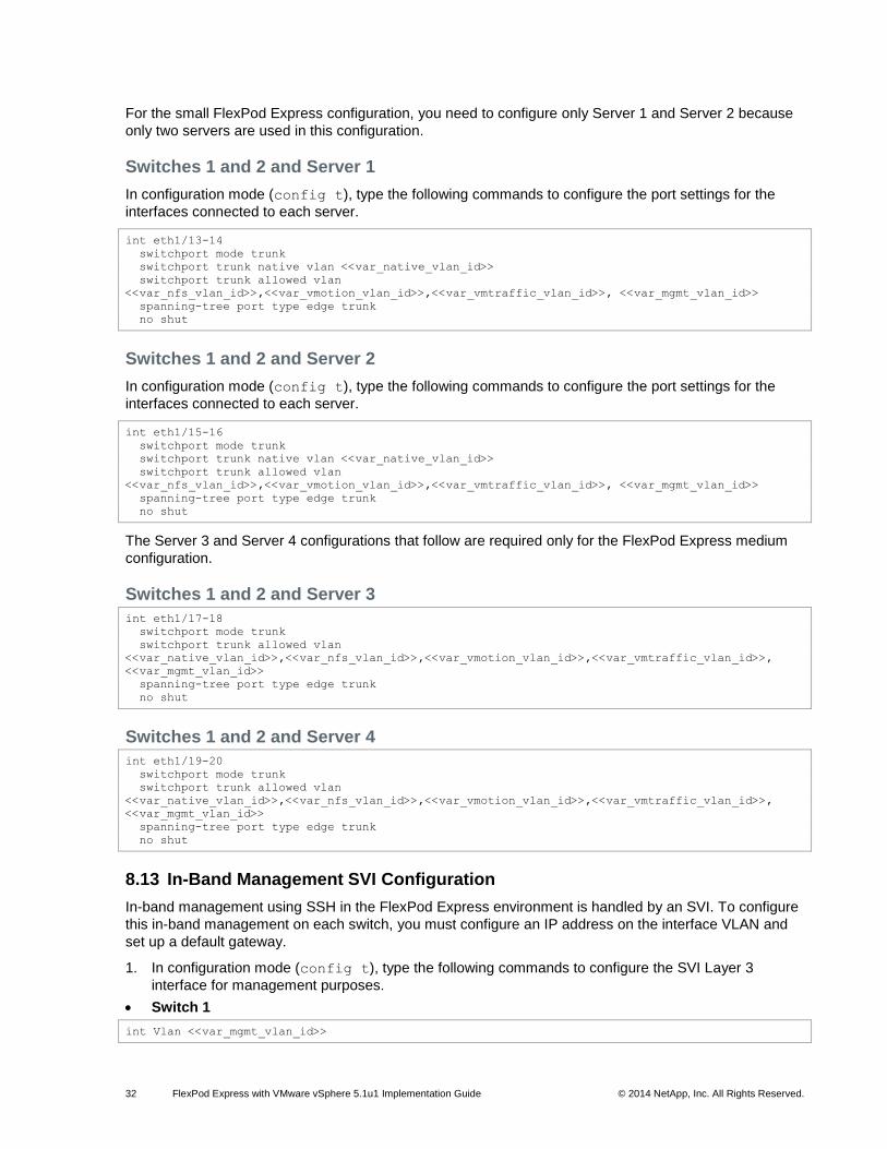
For the small FlexPod Express configuration, you need to configure only Server 1 and Server 2 because
only two servers are used in this configuration.
Switches 1 and 2 and Server 1
In configuration mode (config t), type the following commands to configure the port settings for the
interfaces connected to each server.
int eth1/13-14
switchport mode trunk
switchport trunk native vlan <<var_native_vlan_id>>
switchport trunk allowed vlan
<<var_nfs_vlan_id>>,<<var_vmotion_vlan_id>>,<<var_vmtraffic_vlan_id>>, <<var_mgmt_vlan_id>>
spanning-tree port type edge trunk
no shut
Switches 1 and 2 and Server 2
In configuration mode (config t), type the following commands to configure the port settings for the
interfaces connected to each server.
int eth1/15-16
switchport mode trunk
switchport trunk native vlan <<var_native_vlan_id>>
switchport trunk allowed vlan
<<var_nfs_vlan_id>>,<<var_vmotion_vlan_id>>,<<var_vmtraffic_vlan_id>>, <<var_mgmt_vlan_id>>
spanning-tree port type edge trunk
no shut
The Server 3 and Server 4 configurations that follow are required only for the FlexPod Express medium
configuration.
Switches 1 and 2 and Server 3
int eth1/17-18
switchport mode trunk
switchport trunk allowed vlan
<<var_native_vlan_id>>,<<var_nfs_vlan_id>>,<<var_vmotion_vlan_id>>,<<var_vmtraffic_vlan_id>>,
<<var_mgmt_vlan_id>>
spanning-tree port type edge trunk
no shut
Switches 1 and 2 and Server 4
int eth1/19-20
switchport mode trunk
switchport trunk allowed vlan
<<var_native_vlan_id>>,<<var_nfs_vlan_id>>,<<var_vmotion_vlan_id>>,<<var_vmtraffic_vlan_id>>,
<<var_mgmt_vlan_id>>
spanning-tree port type edge trunk
no shut
8.13 In-Band Management SVI Configuration
In-band management using SSH in the FlexPod Express environment is handled by an SVI. To configure
this in-band management on each switch, you must configure an IP address on the interface VLAN and
set up a default gateway.
1. In configuration mode (config t), type the following commands to configure the SVI Layer 3
interface for management purposes.
Switch 1
int Vlan <<var_mgmt_vlan_id>>
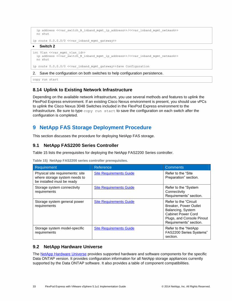
33 FlexPod Express with VMware vSphere 5.1u1 Implementation Guide © 2014 NetApp, Inc. All Rights Reserved.
ip address <<var_switch_A_inband_mgmt_ip_address>>/<<var_inband_mgmt_netmask>>
no shut
ip route 0.0.0.0/0 <<var_inband_mgmt_gateway>>
Switch 2
int Vlan <<var_mgmt_vlan_id>>
ip address <<var_switch_B_inband_mgmt_ip_address>>/<<var_inband_mgmt_netmask>>
no shut
ip route 0.0.0.0/0 <<var_inband_mgmt_gateway>>Save Configuration
2. Save the configuration on both switches to help configuration persistence.
copy run start
8.14 Uplink to Existing Network Infrastructure
Depending on the available network infrastructure, you use several methods and features to uplink the
FlexPod Express environment. If an existing Cisco Nexus environment is present, you should use vPCs
to uplink the Cisco Nexus 3048 Switches included in the FlexPod Express environment to the
infrastructure. Be sure to type copy run start to save the configuration on each switch after the
configuration is completed.
9 NetApp FAS Storage Deployment Procedure
This section discusses the procedure for deploying NetApp FAS storage.
9.1 NetApp FAS2200 Series Controller
Table 15 lists the prerequisites for deploying the NetApp FAS2200 Series controller.
Table 15) NetApp FAS2200 series controller prerequisites.
Requirement Reference Comments
Physical site requirements: site where storage system needs to be installed must be ready
Site Requirements Guide Refer to the “Site Preparation” section.
Storage system connectivity requirements
Site Requirements Guide Refer to the “System Connectivity Requirements” section.
Storage system general power requirements
Site Requirements Guide Refer to the “Circuit Breaker, Power Outlet Balancing, System Cabinet Power Cord Plugs, and Console Pinout Requirements” section.
Storage system model-specific requirements
Site Requirements Guide Refer to the “NetApp FAS2200 Series Systems” section.
9.2 NetApp Hardware Universe
The NetApp Hardware Universe provides supported hardware and software components for the specific
Data ONTAP version. It provides configuration information for all NetApp storage appliances currently
supported by the Data ONTAP software. It also provides a table of component compatibilities.

34 FlexPod Express with VMware vSphere 5.1u1 Implementation Guide © 2014 NetApp, Inc. All Rights Reserved.
1. Make sure that the hardware and software components are supported with the version of Data ONTAP that you plan to install by checking the NetApp Hardware Universe at the NetApp Support site.
2. Access the Hardware Universe application to view the system configuration guides. Select the Controllers tab to view the compatibility between Data ONTAP software versions and NetApp storage appliances with the desired specifications.
3. Alternatively, to compare components by storage appliance, click Compare Storage Systems.
Nodes 1 and 2
Follow the physical installation procedures for the controllers in the NetApp FAS2200 documentation at
the NetApp Support site.
9.3 Clustered Data ONTAP 8.2
These steps provide details for assigning disk ownership and performing disk initialization and
verification.
Node 1
1. Connect to the storage system console port. You should see a Loader-A prompt. However, if the storage system is in a reboot loop, press Ctrl-C to exit the autoboot loop when you see the following message:
Starting AUTOBOOT press Ctrl-C to abort…
2. From the Loader-A prompt, enter:
printenv
3. If the last-OS-booted-ver parameter is not set to 8.2, proceed to step 4 to load Data ONTAP 8.2
software. If Data ONTAP 8.2 is already loaded, proceed to step 16.
4. Allow the system to boot.
boot_ontap
5. Press Ctrl-C when the Press Ctrl-C for Boot Menu message appears.
Note: If Data ONTAP 8.2 is not the version of software being booted, proceed with the following steps to install new software. If Data ONTAP 8.2 is the version being booted, then select option 8 and yes (y) to reboot the node. Then proceed with step 15.
6. To install new software, select option 7.
7
7. Answer yes (y) to perform a nondisruptive upgrade.
y
8. Select e0M for the network port you want to use for the download.
e0M
9. Select yes (y) to reboot now.
y
10. Enter the IP address, netmask, and default gateway for e0M in their respective places.
<<var_fas01_mgmt_ip>> <<var_fas01_mgmt_netmask>> <<var_fas01_mgmt_gateway>>
11. Enter the URL at which the software is located.
<<var_url_boot_software>>

35 FlexPod Express with VMware vSphere 5.1u1 Implementation Guide © 2014 NetApp, Inc. All Rights Reserved.
12. Press Enter for the user name, indicating no user name.
Enter
13. Enter yes (y) to set the newly installed software as the default to be used for subsequent reboots.
y
14. Enter yes (y) to reboot the node.
y
Note: When installing new software, the system may perform firmware upgrades to the BIOS and adapter cards, causing reboots and possible stops at the Loader prompt. If these actions occur, the system may deviate from the procedure shown here.
15. Press Ctrl-C to exit autoboot when you see this message:
Starting AUTOBOOT press Ctrl-C to abort…
16. From the Loader-A prompt, enter:
printenv
Note: If bootarg.init.boot_clustered true is not listed, the system is not set to boot in clustered Data ONTAP.
17. If the system is not set to boot in clustered Data ONTAP, at the Loader prompt, enter the following command to make sure the system boots in clustered Data ONTAP:
setenv bootarg.init.boot_clustered true
setenv bootarg.bsdportname e0M
18. At the Loader-A prompt, enter:
autoboot
19. When you see Press Ctrl-C for Boot Menu, enter:
Ctrl - C
20. Select option 4 to perform a clean configuration and initialize all disks:
4
21. Answer yes (y) to the query Zero disks, reset config and install a new file
system:
y
22. Enter yes (y) to erase all the data on the disks:
y
Note: The initialization and creation of the root volume can take 75 minutes or more to complete, depending on the number of disks attached. After initialization is complete, the storage system reboots. You can continue to Node 2 configuration while the disks for Node 1 are being created.
Node 2
1. Connect to the storage system console port. You should see a Loader-A prompt. However, if the storage system is in a reboot loop, press Ctrl-C to exit the autoboot loop when you see this message:
Starting AUTOBOOT press Ctrl-C to abort…
2. From the Loader-A prompt, enter:
printenv

36 FlexPod Express with VMware vSphere 5.1u1 Implementation Guide © 2014 NetApp, Inc. All Rights Reserved.
3. If the last-OS-booted-ver parameter is not set to 8.2, proceed to step 4 to load Data ONTAP 8.2
software. If Data ONTAP 8.2 is already loaded, proceed to step 16.
4. Allow the system to boot.
boot_ontap
5. Press Ctrl-C when Press Ctrl-C for Boot Menu is displayed.
Ctrl-C
Note: If Data ONTAP 8.2 is not the version of software being booted, proceed with the following steps to install new software. If Data ONTAP 8.2 is the version being booted, then select option 8 and yes (y) to reboot the node. Then proceed with step 15.
6. To install new software, select option 7.
7
7. Answer yes (y) to perform a nondisruptive upgrade.
y
8. Select e0M for the network port you want to use for the download.
e0M
9. Select yes (y) to reboot now.
y
10. Enter the IP address, netmask, and default gateway for e0M in their respective places.
<<var_fas02_mgmt_ip>> <<var_fas02_mgmt_netmask>> <<var_fas02_mgmt_gateway>>
11. Enter the URL at which the software is located.
Note: You must be able to ping this web server.
<<var_url_boot_software>>
12. Press Enter for the user name, indicating no user name.
Enter
13. Select yes (y) to set the newly installed software as the default to be used for subsequent reboots.
y
14. Select yes (y) to reboot the node.
y
Note: When installing new software, the system may perform firmware upgrades to the BIOS and adapter cards, causing reboots and possible stops at the Loader prompt. If these actions occur, the system may deviate from the procedure shown here.
15. Press Ctrl-C to exit autoboot when you see this message:
Starting AUTOBOOT press Ctrl-C to abort…
16. From the Loader-A prompt, enter:
printenv
Note: If bootarg.init.boot_clustered true is not listed, the system is not set to boot in clustered Data ONTAP.
17. If the system is not set to boot in clustered Data ONTAP, at the Loader prompt, enter the following command to make sure that the system boots in clustered Data ONTAP:
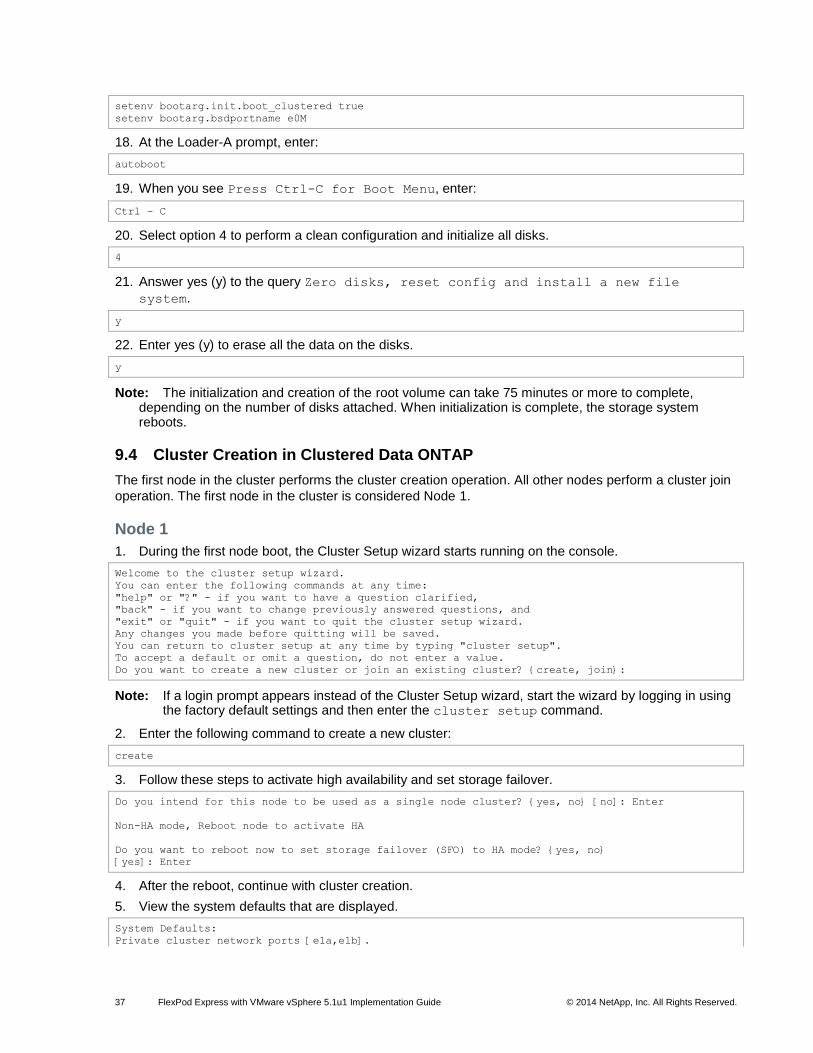
37 FlexPod Express with VMware vSphere 5.1u1 Implementation Guide © 2014 NetApp, Inc. All Rights Reserved.
setenv bootarg.init.boot_clustered true
setenv bootarg.bsdportname e0M
18. At the Loader-A prompt, enter:
autoboot
19. When you see Press Ctrl-C for Boot Menu, enter:
Ctrl – C
20. Select option 4 to perform a clean configuration and initialize all disks.
4
21. Answer yes (y) to the query Zero disks, reset config and install a new file
system.
y
22. Enter yes (y) to erase all the data on the disks.
y
Note: The initialization and creation of the root volume can take 75 minutes or more to complete, depending on the number of disks attached. When initialization is complete, the storage system reboots.
9.4 Cluster Creation in Clustered Data ONTAP
The first node in the cluster performs the cluster creation operation. All other nodes perform a cluster join
operation. The first node in the cluster is considered Node 1.
Node 1
1. During the first node boot, the Cluster Setup wizard starts running on the console.
Welcome to the cluster setup wizard.
You can enter the following commands at any time:
"help" or "?" - if you want to have a question clarified,
"back" - if you want to change previously answered questions, and
"exit" or "quit" - if you want to quit the cluster setup wizard.
Any changes you made before quitting will be saved.
You can return to cluster setup at any time by typing "cluster setup".
To accept a default or omit a question, do not enter a value.
Do you want to create a new cluster or join an existing cluster? {create, join}:
Note: If a login prompt appears instead of the Cluster Setup wizard, start the wizard by logging in using the factory default settings and then enter the cluster setup command.
2. Enter the following command to create a new cluster:
create
3. Follow these steps to activate high availability and set storage failover.
Do you intend for this node to be used as a single node cluster? {yes, no} [no]: Enter
Non-HA mode, Reboot node to activate HA
Do you want to reboot now to set storage failover (SFO) to HA mode? {yes, no}
[yes]: Enter
4. After the reboot, continue with cluster creation.
5. View the system defaults that are displayed.
System Defaults:
Private cluster network ports [e1a,e1b].

38 FlexPod Express with VMware vSphere 5.1u1 Implementation Guide © 2014 NetApp, Inc. All Rights Reserved.
Cluster port MTU values will be set to 9000.
Cluster interface IP addresses will be automatically generated.
The cluster will be connected using network switches.
Do you want to use these defaults? {yes, no} [yes]:
5. NetApp recommends accepting the system defaults. To accept the system defaults, press Enter.
Note: The cluster is created; this process can take a minute or two.
6. For the license key section, make sure that NFS is licensed during the setup process.
7. The steps to create a cluster are displayed.
Enter the cluster name: <<var_clustername>>
Enter the cluster base license key: <<var_cluster_base_license_key>>
Creating cluster <<var_clustername>>
Enter an additional license key []:
Note: For this validated architecture, you should install license keys for Fibre Channel Protocol (FCP) and NetApp SnapRestore
®, FlexClone
®, and SnapManager
® suite. After you finish entering the
license keys, press Enter.
Enter the cluster administrators (username “admin”) password: <<var_admin_password>>
Retype the password: <<var_admin_password>>
Enter the cluster management interface port [e0a]: e0M
Enter the cluster management interface IP address: <<var_clustermgmt_ip>>
Enter the cluster management interface netmask: <<var_clustermgmt_netmask>>
Enter the cluster management interface default gateway: <<var_clustermgmt_gateway>>
8. Enter the DNS domain name.
Enter the DNS domain names:<<var_dns_domain_name>>
Enter the name server IP addresses:<<var_nameserver_ip>>
Note: If you have more than one name server IP address, separate them with a comma.
9. Set up the node.
Where is the controller located []:<<var_fas_location>>
Enter the node management interface port [e0M]: Enter
Enter the node management interface IP address: <<var_fas01_mgmt_ip>>
Enter the node management interface netmask:<<var_fas01_mgmt_netmask>>
Enter the node management interface default gateway:<<var_fas01_mgmt_gateway>>
10. Press Enter to accept the AutoSupport™
message.
11. Log into the node and set the privilege mode to advanced.
set -privilege advanced
12. Enable the switchless cluster.
network options switchless-cluster modify true
13. Make sure the switchless cluster is enabled.
FAS2240-Cluster::*> network options switchless-cluster show
Enable Switchless Cluster: true
14. Set the privilege mode back to admin.
set -privilege admin
15. Reboot Node 1.
system node reboot –node <<var_fas01>>
Warning: Are you sure you want to reboot the node? {y|n}: y
16. When you see Press Ctrl-C for Boot Menu, enter:

39 FlexPod Express with VMware vSphere 5.1u1 Implementation Guide © 2014 NetApp, Inc. All Rights Reserved.
Ctrl – C
17. Select 5 to boot into maintenance mode.
5
18. When prompted Continue with boot?, enter yes (y).
19. To verify the high-availability status of your environment, run the following command:
ha-config show
Note: If either component is not in high-availability mode, use the ha-config modify command to put the component in high-availability mode.
20. Reboot the controller.
halt
21. At the Loader-A prompt, enter:
autoboot
22. Log in to the cluster.
23. Data ONTAP assigns disks to storage controllers automatically if the disk autoassign setting is turned
on. Use the storage disk option show -fields autoassign command to verify the
setting.
24. If disk autoassign is turned on, skip to the section 9.5, “Cluster Join in Clustered Data ONTAP.” Otherwise, continue with step 25.
25. Reboot Node 1.
system node reboot –node <<var_fas01>>
Warning: Are you sure you want to reboot the node? {y|n}: y
26. When you see Press Ctrl-C for Boot Menu, enter:
Ctrl – C
27. Select 5 to boot into maintenance mode.
5
28. When prompted Continue with boot?, enter yes (y).
29. To see how many disks are unowned, enter:
disk show -a
Note: No disks should be owned in this list.
30. Assign disks.
Note: For the FlexPod Express small configuration, <<var_#_of_disks>> should equal 9 for Controller 1.
Note: For the FlexPod Express medium configuration, <<var_#_of_disks>> should equal 21 for Controller 1.
disk assign –n <<var_#_of_disks>>
31. Reboot the controller.
halt
32. At the Loader-A prompt, enter:
autoboot
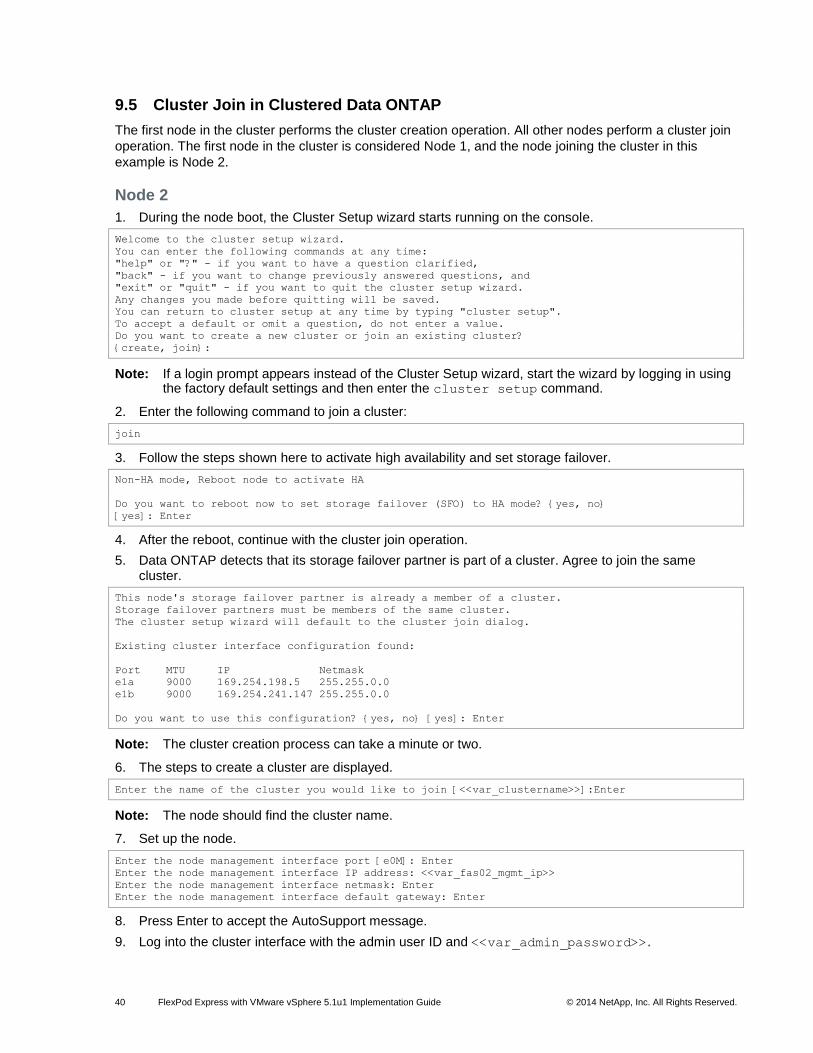
40 FlexPod Express with VMware vSphere 5.1u1 Implementation Guide © 2014 NetApp, Inc. All Rights Reserved.
9.5 Cluster Join in Clustered Data ONTAP
The first node in the cluster performs the cluster creation operation. All other nodes perform a cluster join
operation. The first node in the cluster is considered Node 1, and the node joining the cluster in this
example is Node 2.
Node 2
1. During the node boot, the Cluster Setup wizard starts running on the console.
Welcome to the cluster setup wizard.
You can enter the following commands at any time:
"help" or "?" - if you want to have a question clarified,
"back" - if you want to change previously answered questions, and
"exit" or "quit" - if you want to quit the cluster setup wizard.
Any changes you made before quitting will be saved.
You can return to cluster setup at any time by typing "cluster setup".
To accept a default or omit a question, do not enter a value.
Do you want to create a new cluster or join an existing cluster?
{create, join}:
Note: If a login prompt appears instead of the Cluster Setup wizard, start the wizard by logging in using the factory default settings and then enter the cluster setup command.
2. Enter the following command to join a cluster:
join
3. Follow the steps shown here to activate high availability and set storage failover.
Non-HA mode, Reboot node to activate HA
Do you want to reboot now to set storage failover (SFO) to HA mode? {yes, no}
[yes]: Enter
4. After the reboot, continue with the cluster join operation.
5. Data ONTAP detects that its storage failover partner is part of a cluster. Agree to join the same cluster.
This node's storage failover partner is already a member of a cluster.
Storage failover partners must be members of the same cluster.
The cluster setup wizard will default to the cluster join dialog.
Existing cluster interface configuration found:
Port MTU IP Netmask
e1a 9000 169.254.198.5 255.255.0.0
e1b 9000 169.254.241.147 255.255.0.0
Do you want to use this configuration? {yes, no} [yes]: Enter
Note: The cluster creation process can take a minute or two.
6. The steps to create a cluster are displayed.
Enter the name of the cluster you would like to join [<<var_clustername>>]:Enter
Note: The node should find the cluster name.
7. Set up the node.
Enter the node management interface port [e0M]: Enter
Enter the node management interface IP address: <<var_fas02_mgmt_ip>>
Enter the node management interface netmask: Enter
Enter the node management interface default gateway: Enter
8. Press Enter to accept the AutoSupport message.
9. Log into the cluster interface with the admin user ID and <<var_admin_password>>.

41 FlexPod Express with VMware vSphere 5.1u1 Implementation Guide © 2014 NetApp, Inc. All Rights Reserved.
10. Reboot Node 2.
system node reboot <<var_fas02>>
y
11. When you see Press Ctrl-C for Boot Menu, enter:
Ctrl – C
12. Select 5 to boot into maintenance mode.
5
13. At the question, Continue with boot?, enter:
y
14. To verify the high-availability status of your environment, enter:
ha-config show
Note: If either component is not in high-availability mode, use the ha-config modify command to put the components in high-availability mode.
15. Reboot the controller.
halt
16. At the Loader-A prompt, enter:
Autoboot
17. Log into the cluster.
18. Data ONTAP assigns disks to storage controllers automatically if the disk autoassign setting is turned
on. Use the storage disk option show -fields autoassign command to verify the setting.
19. If disk autoassign is turned on, skip to the section 9.6, “Log into the Cluster.” Otherwise, continue
with step 20.
20. Reboot Node 2.
system node reboot –node <<var_fas02>>
Warning: Are you sure you want to reboot the node? {y|n}: y
21. When you see Press Ctrl-C for Boot Menu, enter:
Ctrl – C
22. Select 5 to boot into maintenance mode.
5
23. When prompted Continue with boot?, enter yes (y).
24. To see how many disks are unowned, enter:
disk show -a
Note: No disks should be owned in this list.
25. Assign disks.
Note: For both the small and medium FlexPod Express configurations, <<var_#_of_disks>> should equal 3 for Controller 2.
disk assign –n <<var_#_of_disks>>
26. Reboot the controller.
halt
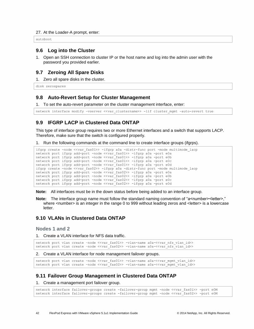
42 FlexPod Express with VMware vSphere 5.1u1 Implementation Guide © 2014 NetApp, Inc. All Rights Reserved.
27. At the Loader-A prompt, enter:
autoboot
9.6 Log into the Cluster
1. Open an SSH connection to cluster IP or the host name and log into the admin user with the password you provided earlier.
9.7 Zeroing All Spare Disks
1. Zero all spare disks in the cluster.
disk zerospares
9.8 Auto-Revert Setup for Cluster Management
1. To set the auto-revert parameter on the cluster management interface, enter:
network interface modify –vserver <<var_clustername>> -lif cluster_mgmt –auto-revert true
9.9 IFGRP LACP in Clustered Data ONTAP
This type of interface group requires two or more Ethernet interfaces and a switch that supports LACP.
Therefore, make sure that the switch is configured properly.
1. Run the following commands at the command line to create interface groups (ifgrps).
ifgrp create -node <<var_fas01>> -ifgrp a0a -distr-func port -mode multimode_lacp
network port ifgrp add-port -node <<var_fas01>> -ifgrp a0a -port e0a
network port ifgrp add-port -node <<var_fas01>> -ifgrp a0a -port e0b
network port ifgrp add-port -node <<var_fas01>> -ifgrp a0a -port e0c
network port ifgrp add-port -node <<var_fas01>> -ifgrp a0a -port e0d
ifgrp create -node <<var_fas02>> -ifgrp a0a -distr-func port -mode multimode_lacp
network port ifgrp add-port -node <<var_fas02>> -ifgrp a0a -port e0a
network port ifgrp add-port -node <<var_fas02>> -ifgrp a0a -port e0b
network port ifgrp add-port -node <<var_fas02>> -ifgrp a0a -port e0c
network port ifgrp add-port -node <<var_fas02>> -ifgrp a0a -port e0d
Note: All interfaces must be in the down status before being added to an interface group.
Note: The interface group name must follow the standard naming convention of “a<number><letter>,” where <number> is an integer in the range 0 to 999 without leading zeros and <letter> is a lowercase letter.
9.10 VLANs in Clustered Data ONTAP
Nodes 1 and 2
1. Create a VLAN interface for NFS data traffic.
network port vlan create –node <<var_fas01>> -vlan-name a0a-<<var_nfs_vlan_id>>
network port vlan create –node <<var_fas02>> -vlan-name a0a-<<var_nfs_vlan_id>>
2. Create a VLAN interface for node management failover groups.
network port vlan create –node <<var_fas01>> -vlan-name a0a-<<var_mgmt_vlan_id>>
network port vlan create –node <<var_fas02>> -vlan-name a0a-<<var_mgmt_vlan_id>>
9.11 Failover Group Management in Clustered Data ONTAP
1. Create a management port failover group.
network interface failover-groups create -failover-group mgmt -node <<var_fas01>> -port e0M
network interface failover-groups create -failover-group mgmt -node <<var_fas02>> -port e0M
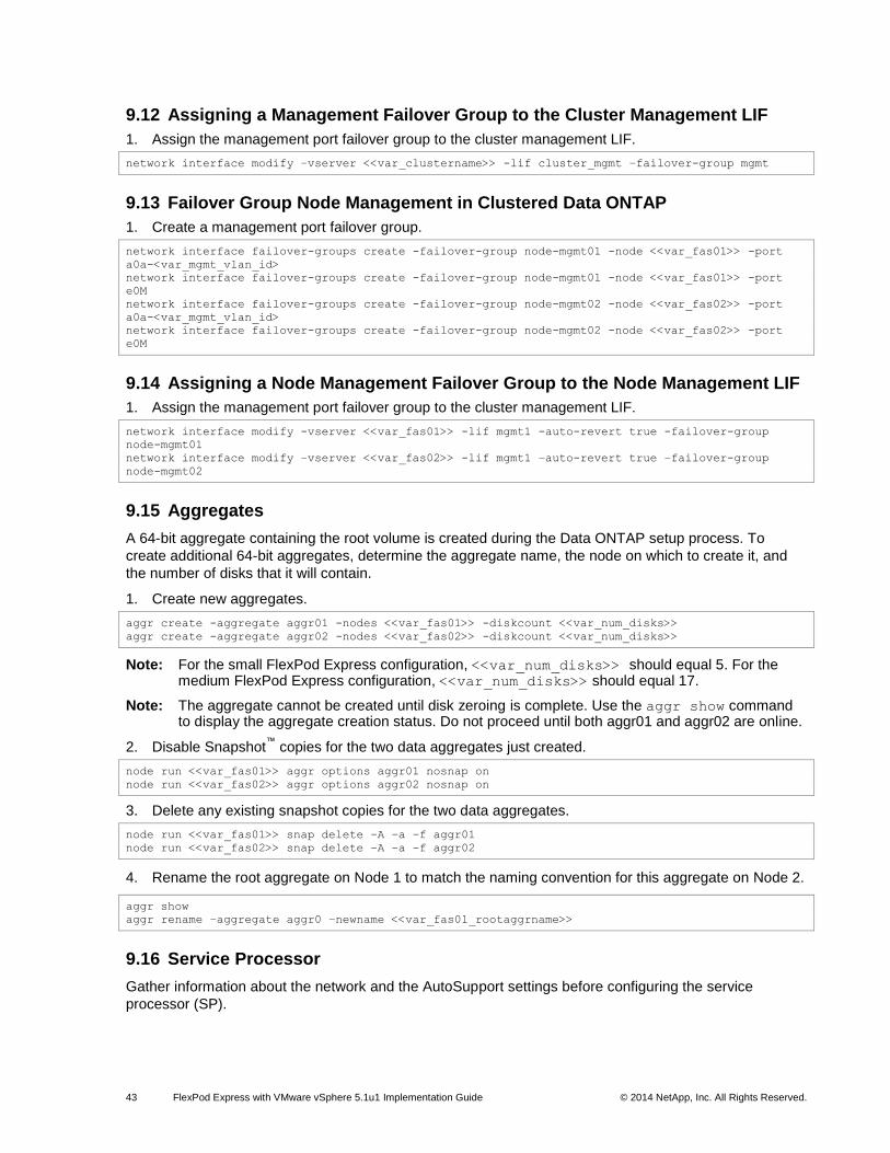
43 FlexPod Express with VMware vSphere 5.1u1 Implementation Guide © 2014 NetApp, Inc. All Rights Reserved.
9.12 Assigning a Management Failover Group to the Cluster Management LIF
1. Assign the management port failover group to the cluster management LIF.
network interface modify –vserver <<var_clustername>> -lif cluster_mgmt –failover-group mgmt
9.13 Failover Group Node Management in Clustered Data ONTAP
1. Create a management port failover group.
network interface failover-groups create -failover-group node-mgmt01 -node <<var_fas01>> -port
a0a-<var_mgmt_vlan_id>
network interface failover-groups create -failover-group node-mgmt01 -node <<var_fas01>> -port
e0M
network interface failover-groups create -failover-group node-mgmt02 -node <<var_fas02>> -port
a0a-<var_mgmt_vlan_id>
network interface failover-groups create -failover-group node-mgmt02 -node <<var_fas02>> -port
e0M
9.14 Assigning a Node Management Failover Group to the Node Management LIF
1. Assign the management port failover group to the cluster management LIF.
network interface modify -vserver <<var_fas01>> -lif mgmt1 -auto-revert true -failover-group
node-mgmt01
network interface modify –vserver <<var_fas02>> -lif mgmt1 –auto-revert true –failover-group
node-mgmt02
9.15 Aggregates
A 64-bit aggregate containing the root volume is created during the Data ONTAP setup process. To
create additional 64-bit aggregates, determine the aggregate name, the node on which to create it, and
the number of disks that it will contain.
1. Create new aggregates.
aggr create -aggregate aggr01 -nodes <<var_fas01>> -diskcount <<var_num_disks>>
aggr create -aggregate aggr02 -nodes <<var_fas02>> -diskcount <<var_num_disks>>
Note: For the small FlexPod Express configuration, <<var_num_disks>> should equal 5. For the medium FlexPod Express configuration, <<var_num_disks>> should equal 17.
Note: The aggregate cannot be created until disk zeroing is complete. Use the aggr show command to display the aggregate creation status. Do not proceed until both aggr01 and aggr02 are online.
2. Disable Snapshot™
copies for the two data aggregates just created.
node run <<var_fas01>> aggr options aggr01 nosnap on
node run <<var_fas02>> aggr options aggr02 nosnap on
3. Delete any existing snapshot copies for the two data aggregates.
node run <<var_fas01>> snap delete –A –a –f aggr01
node run <<var_fas02>> snap delete –A –a –f aggr02
4. Rename the root aggregate on Node 1 to match the naming convention for this aggregate on Node 2.
aggr show
aggr rename –aggregate aggr0 –newname <<var_fas01_rootaggrname>>
9.16 Service Processor
Gather information about the network and the AutoSupport settings before configuring the service
processor (SP).
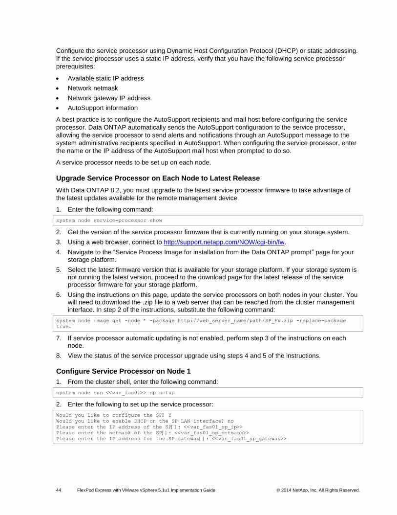
44 FlexPod Express with VMware vSphere 5.1u1 Implementation Guide © 2014 NetApp, Inc. All Rights Reserved.
Configure the service processor using Dynamic Host Configuration Protocol (DHCP) or static addressing.
If the service processor uses a static IP address, verify that you have the following service processor
prerequisites:
Available static IP address
Network netmask
Network gateway IP address
AutoSupport information
A best practice is to configure the AutoSupport recipients and mail host before configuring the service
processor. Data ONTAP automatically sends the AutoSupport configuration to the service processor,
allowing the service processor to send alerts and notifications through an AutoSupport message to the
system administrative recipients specified in AutoSupport. When configuring the service processor, enter
the name or the IP address of the AutoSupport mail host when prompted to do so.
A service processor needs to be set up on each node.
Upgrade Service Processor on Each Node to Latest Release
With Data ONTAP 8.2, you must upgrade to the latest service processor firmware to take advantage of
the latest updates available for the remote management device.
1. Enter the following command:
system node service-processor show
2. Get the version of the service processor firmware that is currently running on your storage system.
3. Using a web browser, connect to http://support.netapp.com/NOW/cgi-bin/fw.
4. Navigate to the “Service Process Image for installation from the Data ONTAP prompt” page for your storage platform.
5. Select the latest firmware version that is available for your storage platform. If your storage system is not running the latest version, proceed to the download page for the latest release of the service processor firmware for your storage platform.
6. Using the instructions on this page, update the service processors on both nodes in your cluster. You will need to download the .zip file to a web server that can be reached from the cluster management interface. In step 2 of the instructions, substitute the following command:
system node image get –node * -package http://web_server_name/path/SP_FW.zip -replace-package
true.
7. If service processor automatic updating is not enabled, perform step 3 of the instructions on each node.
8. View the status of the service processor upgrade using steps 4 and 5 of the instructions.
Configure Service Processor on Node 1
1. From the cluster shell, enter the following command:
system node run <<var_fas01>> sp setup
2. Enter the following to set up the service processor:
Would you like to configure the SP? Y
Would you like to enable DHCP on the SP LAN interface? no
Please enter the IP address of the SP[]: <<var_fas01_sp_ip>>
Please enter the netmask of the SP[]: <<var_fas01_sp_netmask>>
Please enter the IP address for the SP gateway[]: <<var_fas01_sp_gateway>>
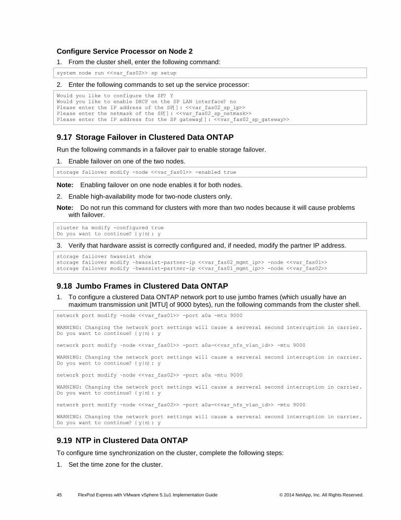
45 FlexPod Express with VMware vSphere 5.1u1 Implementation Guide © 2014 NetApp, Inc. All Rights Reserved.
Configure Service Processor on Node 2
1. From the cluster shell, enter the following command:
system node run <<var_fas02>> sp setup
2. Enter the following commands to set up the service processor:
Would you like to configure the SP? Y
Would you like to enable DHCP on the SP LAN interface? no
Please enter the IP address of the SP[]: <<var_fas02_sp_ip>>
Please enter the netmask of the SP[]: <<var_fas02_sp_netmask>>
Please enter the IP address for the SP gateway[]: <<var_fas02_sp_gateway>>
9.17 Storage Failover in Clustered Data ONTAP
Run the following commands in a failover pair to enable storage failover.
1. Enable failover on one of the two nodes.
storage failover modify -node <<var_fas01>> -enabled true
Note: Enabling failover on one node enables it for both nodes.
2. Enable high-availability mode for two-node clusters only.
Note: Do not run this command for clusters with more than two nodes because it will cause problems with failover.
cluster ha modify -configured true
Do you want to continue? {y|n}: y
3. Verify that hardware assist is correctly configured and, if needed, modify the partner IP address.
storage failover hwassist show
storage failover modify –hwassist-partner-ip <<var_fas02_mgmt_ip>> -node <<var_fas01>>
storage failover modify –hwassist-partner-ip <<var_fas01_mgmt_ip>> -node <<var_fas02>>
9.18 Jumbo Frames in Clustered Data ONTAP
1. To configure a clustered Data ONTAP network port to use jumbo frames (which usually have an maximum transmission unit [MTU] of 9000 bytes), run the following commands from the cluster shell.
network port modify -node <<var_fas01>> -port a0a -mtu 9000
WARNING: Changing the network port settings will cause a serveral second interruption in carrier.
Do you want to continue? {y|n}: y
network port modify –node <<var_fas01>> -port a0a-<<var_nfs_vlan_id>> -mtu 9000
WARNING: Changing the network port settings will cause a serveral second interruption in carrier.
Do you want to continue? {y|n}: y
network port modify –node <<var_fas02>> -port a0a -mtu 9000
WARNING: Changing the network port settings will cause a serveral second interruption in carrier.
Do you want to continue? {y|n}: y
network port modify –node <<var_fas02>> -port a0a-<<var_nfs_vlan_id>> -mtu 9000
WARNING: Changing the network port settings will cause a serveral second interruption in carrier.
Do you want to continue? {y|n}: y
9.19 NTP in Clustered Data ONTAP
To configure time synchronization on the cluster, complete the following steps:
1. Set the time zone for the cluster.
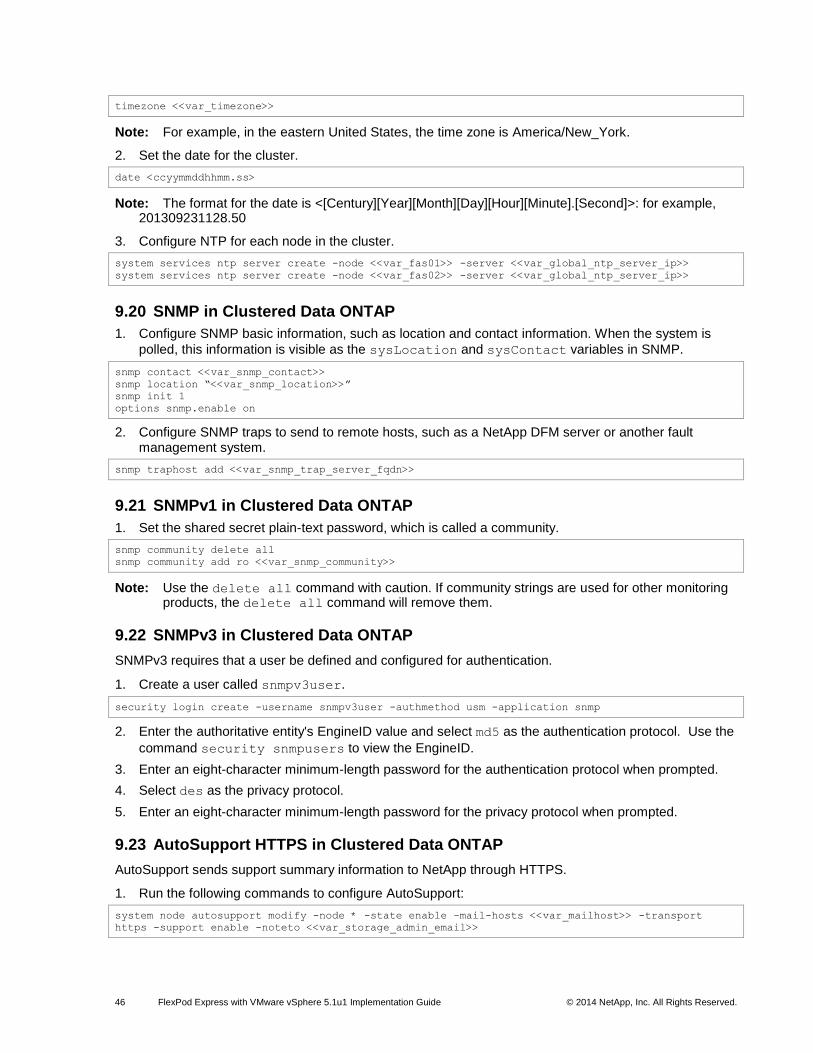
46 FlexPod Express with VMware vSphere 5.1u1 Implementation Guide © 2014 NetApp, Inc. All Rights Reserved.
timezone <<var_timezone>>
Note: For example, in the eastern United States, the time zone is America/New_York.
2. Set the date for the cluster.
date <ccyymmddhhmm.ss>
Note: The format for the date is <[Century][Year][Month][Day][Hour][Minute].[Second]>: for example, 201309231128.50
3. Configure NTP for each node in the cluster.
system services ntp server create -node <<var_fas01>> -server <<var_global_ntp_server_ip>>
system services ntp server create -node <<var_fas02>> -server <<var_global_ntp_server_ip>>
9.20 SNMP in Clustered Data ONTAP
1. Configure SNMP basic information, such as location and contact information. When the system is
polled, this information is visible as the sysLocation and sysContact variables in SNMP.
snmp contact <<var_snmp_contact>>
snmp location “<<var_snmp_location>>”
snmp init 1
options snmp.enable on
2. Configure SNMP traps to send to remote hosts, such as a NetApp DFM server or another fault management system.
snmp traphost add <<var_snmp_trap_server_fqdn>>
9.21 SNMPv1 in Clustered Data ONTAP
1. Set the shared secret plain-text password, which is called a community.
snmp community delete all
snmp community add ro <<var_snmp_community>>
Note: Use the delete all command with caution. If community strings are used for other monitoring products, the delete all command will remove them.
9.22 SNMPv3 in Clustered Data ONTAP
SNMPv3 requires that a user be defined and configured for authentication.
1. Create a user called snmpv3user.
security login create -username snmpv3user -authmethod usm -application snmp
2. Enter the authoritative entity's EngineID value and select md5 as the authentication protocol. Use the
command security snmpusers to view the EngineID.
3. Enter an eight-character minimum-length password for the authentication protocol when prompted.
4. Select des as the privacy protocol.
5. Enter an eight-character minimum-length password for the privacy protocol when prompted.
9.23 AutoSupport HTTPS in Clustered Data ONTAP
AutoSupport sends support summary information to NetApp through HTTPS.
1. Run the following commands to configure AutoSupport:
system node autosupport modify -node * -state enable –mail-hosts <<var_mailhost>> -transport
https -support enable -noteto <<var_storage_admin_email>>
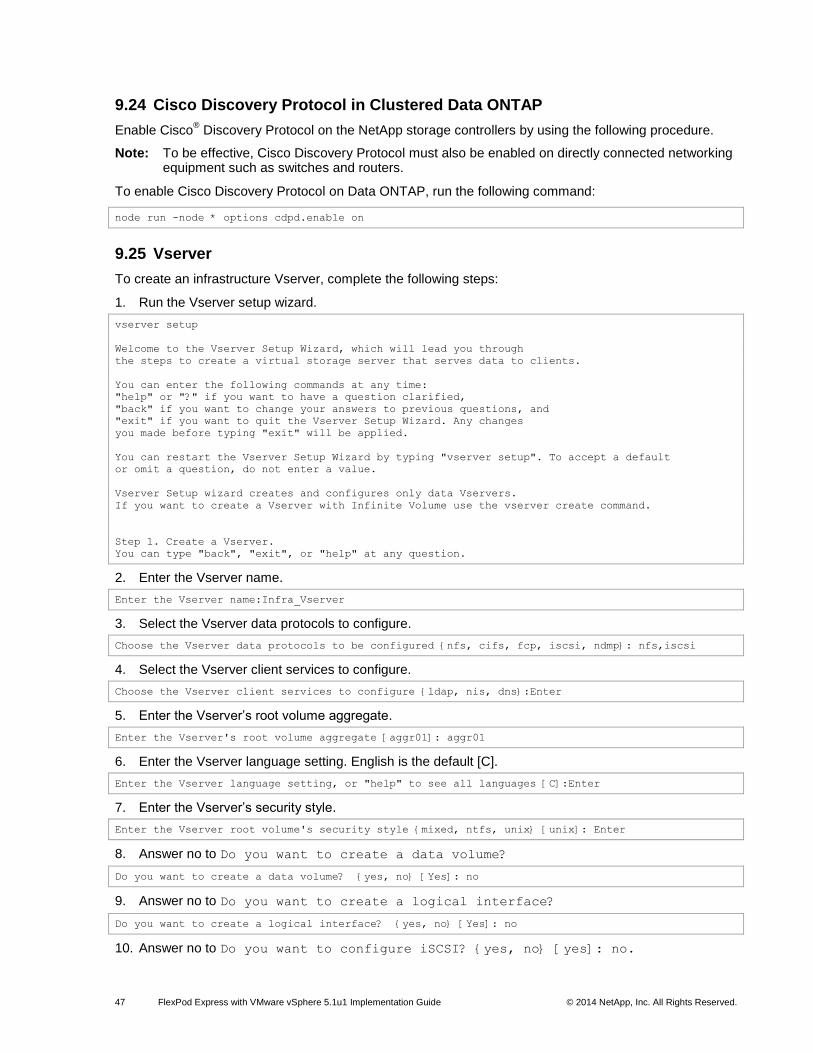
47 FlexPod Express with VMware vSphere 5.1u1 Implementation Guide © 2014 NetApp, Inc. All Rights Reserved.
9.24 Cisco Discovery Protocol in Clustered Data ONTAP
Enable Cisco® Discovery Protocol on the NetApp storage controllers by using the following procedure.
Note: To be effective, Cisco Discovery Protocol must also be enabled on directly connected networking equipment such as switches and routers.
To enable Cisco Discovery Protocol on Data ONTAP, run the following command:
node run -node * options cdpd.enable on
9.25 Vserver
To create an infrastructure Vserver, complete the following steps:
1. Run the Vserver setup wizard.
vserver setup
Welcome to the Vserver Setup Wizard, which will lead you through
the steps to create a virtual storage server that serves data to clients.
You can enter the following commands at any time:
"help" or "?" if you want to have a question clarified,
"back" if you want to change your answers to previous questions, and
"exit" if you want to quit the Vserver Setup Wizard. Any changes
you made before typing "exit" will be applied.
You can restart the Vserver Setup Wizard by typing "vserver setup". To accept a default
or omit a question, do not enter a value.
Vserver Setup wizard creates and configures only data Vservers.
If you want to create a Vserver with Infinite Volume use the vserver create command.
Step 1. Create a Vserver.
You can type "back", "exit", or "help" at any question.
2. Enter the Vserver name.
Enter the Vserver name:Infra_Vserver
3. Select the Vserver data protocols to configure.
Choose the Vserver data protocols to be configured {nfs, cifs, fcp, iscsi, ndmp}: nfs,iscsi
4. Select the Vserver client services to configure.
Choose the Vserver client services to configure {ldap, nis, dns}:Enter
5. Enter the Vserver’s root volume aggregate.
Enter the Vserver's root volume aggregate [aggr01]: aggr01
6. Enter the Vserver language setting. English is the default [C].
Enter the Vserver language setting, or "help" to see all languages [C]:Enter
7. Enter the Vserver’s security style.
Enter the Vserver root volume's security style {mixed, ntfs, unix} [unix]: Enter
8. Answer no to Do you want to create a data volume?
Do you want to create a data volume? {yes, no} [Yes]: no
9. Answer no to Do you want to create a logical interface?
Do you want to create a logical interface? {yes, no} [Yes]: no
10. Answer no to Do you want to configure iSCSI? {yes, no} [yes]: no.
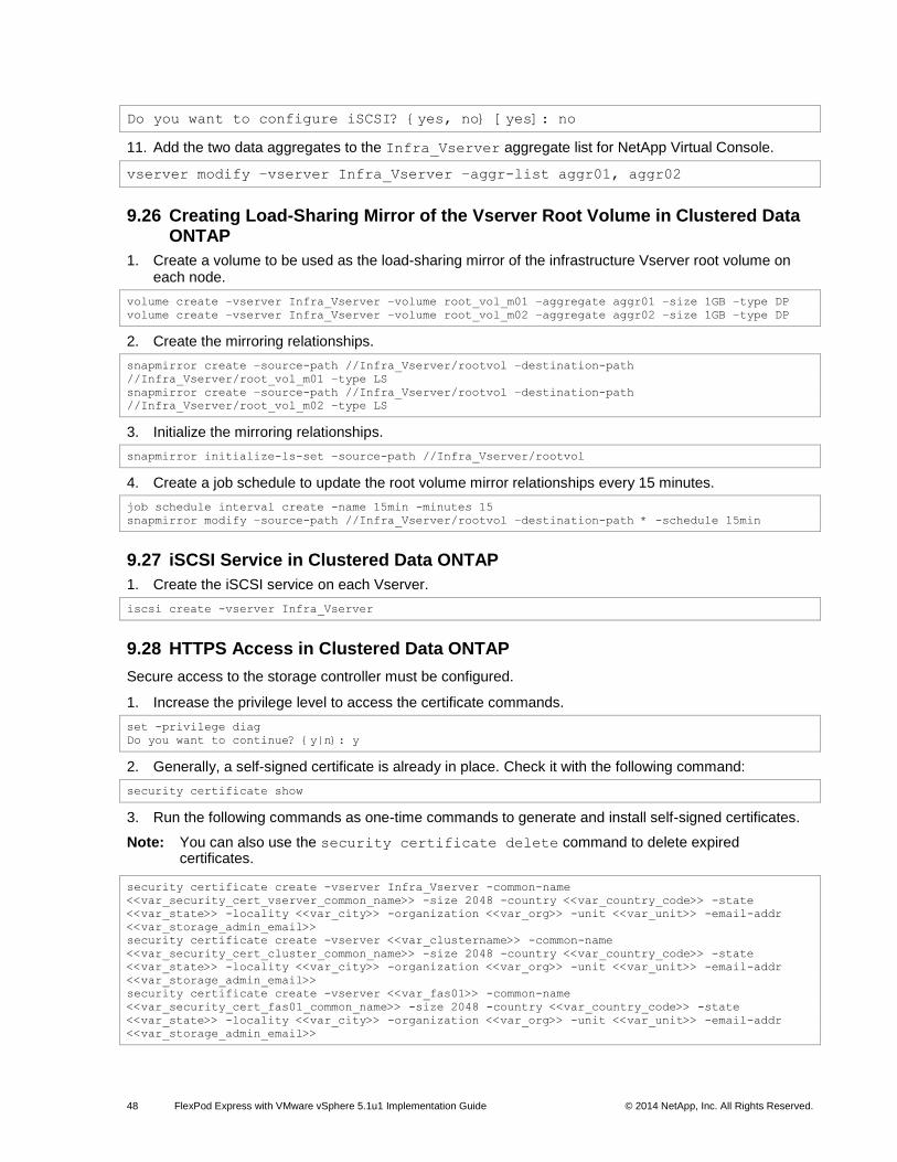
48 FlexPod Express with VMware vSphere 5.1u1 Implementation Guide © 2014 NetApp, Inc. All Rights Reserved.
Do you want to configure iSCSI? {yes, no} [yes]: no
11. Add the two data aggregates to the Infra_Vserver aggregate list for NetApp Virtual Console.
vserver modify –vserver Infra_Vserver –aggr-list aggr01, aggr02
9.26 Creating Load-Sharing Mirror of the Vserver Root Volume in Clustered Data ONTAP
1. Create a volume to be used as the load-sharing mirror of the infrastructure Vserver root volume on each node.
volume create –vserver Infra_Vserver –volume root_vol_m01 –aggregate aggr01 –size 1GB –type DP
volume create –vserver Infra_Vserver –volume root_vol_m02 –aggregate aggr02 –size 1GB –type DP
2. Create the mirroring relationships.
snapmirror create –source-path //Infra_Vserver/rootvol –destination-path
//Infra_Vserver/root_vol_m01 –type LS
snapmirror create –source-path //Infra_Vserver/rootvol –destination-path
//Infra_Vserver/root_vol_m02 –type LS
3. Initialize the mirroring relationships.
snapmirror initialize-ls-set –source-path //Infra_Vserver/rootvol
4. Create a job schedule to update the root volume mirror relationships every 15 minutes.
job schedule interval create -name 15min -minutes 15
snapmirror modify –source-path //Infra_Vserver/rootvol –destination-path * -schedule 15min
9.27 iSCSI Service in Clustered Data ONTAP
1. Create the iSCSI service on each Vserver.
iscsi create -vserver Infra_Vserver
9.28 HTTPS Access in Clustered Data ONTAP
Secure access to the storage controller must be configured.
1. Increase the privilege level to access the certificate commands.
set -privilege diag
Do you want to continue? {y|n}: y
2. Generally, a self-signed certificate is already in place. Check it with the following command:
security certificate show
3. Run the following commands as one-time commands to generate and install self-signed certificates.
Note: You can also use the security certificate delete command to delete expired certificates.
security certificate create -vserver Infra_Vserver -common-name
<<var_security_cert_vserver_common_name>> -size 2048 -country <<var_country_code>> -state
<<var_state>> -locality <<var_city>> -organization <<var_org>> -unit <<var_unit>> -email-addr
<<var_storage_admin_email>>
security certificate create -vserver <<var_clustername>> -common-name
<<var_security_cert_cluster_common_name>> -size 2048 -country <<var_country_code>> -state
<<var_state>> -locality <<var_city>> -organization <<var_org>> -unit <<var_unit>> -email-addr
<<var_storage_admin_email>>
security certificate create -vserver <<var_fas01>> -common-name
<<var_security_cert_fas01_common_name>> -size 2048 -country <<var_country_code>> -state
<<var_state>> -locality <<var_city>> -organization <<var_org>> -unit <<var_unit>> -email-addr
<<var_storage_admin_email>>
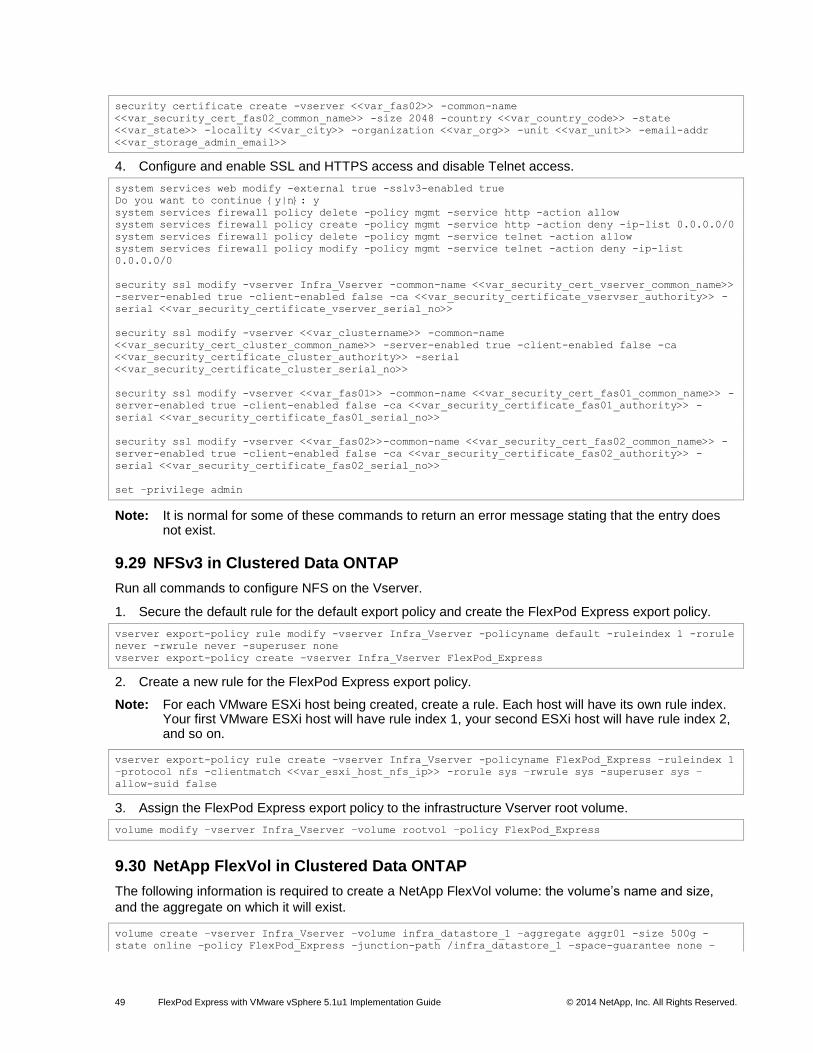
49 FlexPod Express with VMware vSphere 5.1u1 Implementation Guide © 2014 NetApp, Inc. All Rights Reserved.
security certificate create -vserver <<var_fas02>> -common-name
<<var_security_cert_fas02_common_name>> -size 2048 -country <<var_country_code>> -state
<<var_state>> -locality <<var_city>> -organization <<var_org>> -unit <<var_unit>> -email-addr
<<var_storage_admin_email>>
4. Configure and enable SSL and HTTPS access and disable Telnet access.
system services web modify -external true -sslv3-enabled true
Do you want to continue {y|n}: y
system services firewall policy delete -policy mgmt -service http -action allow
system services firewall policy create -policy mgmt -service http -action deny -ip-list 0.0.0.0/0
system services firewall policy delete -policy mgmt -service telnet -action allow
system services firewall policy modify -policy mgmt -service telnet -action deny -ip-list
0.0.0.0/0
security ssl modify -vserver Infra_Vserver -common-name <<var_security_cert_vserver_common_name>>
-server-enabled true -client-enabled false -ca <<var_security_certificate_vservser_authority>> -
serial <<var_security_certificate_vserver_serial_no>>
security ssl modify -vserver <<var_clustername>> -common-name
<<var_security_cert_cluster_common_name>> -server-enabled true -client-enabled false -ca
<<var_security_certificate_cluster_authority>> -serial
<<var_security_certificate_cluster_serial_no>>
security ssl modify -vserver <<var_fas01>> -common-name <<var_security_cert_fas01_common_name>> -
server-enabled true -client-enabled false -ca <<var_security_certificate_fas01_authority>> -
serial <<var_security_certificate_fas01_serial_no>>
security ssl modify -vserver <<var_fas02>>-common-name <<var_security_cert_fas02_common_name>> -
server-enabled true -client-enabled false -ca <<var_security_certificate_fas02_authority>> -
serial <<var_security_certificate_fas02_serial_no>>
set –privilege admin
Note: It is normal for some of these commands to return an error message stating that the entry does not exist.
9.29 NFSv3 in Clustered Data ONTAP
Run all commands to configure NFS on the Vserver.
1. Secure the default rule for the default export policy and create the FlexPod Express export policy.
vserver export-policy rule modify -vserver Infra_Vserver -policyname default -ruleindex 1 -rorule
never -rwrule never -superuser none
vserver export-policy create –vserver Infra_Vserver FlexPod_Express
2. Create a new rule for the FlexPod Express export policy.
Note: For each VMware ESXi host being created, create a rule. Each host will have its own rule index. Your first VMware ESXi host will have rule index 1, your second ESXi host will have rule index 2, and so on.
vserver export-policy rule create –vserver Infra_Vserver -policyname FlexPod_Express –ruleindex 1
–protocol nfs -clientmatch <<var_esxi_host_nfs_ip>> -rorule sys –rwrule sys -superuser sys –
allow-suid false
3. Assign the FlexPod Express export policy to the infrastructure Vserver root volume.
volume modify –vserver Infra_Vserver –volume rootvol –policy FlexPod_Express
9.30 NetApp FlexVol in Clustered Data ONTAP
The following information is required to create a NetApp FlexVol volume: the volume’s name and size,
and the aggregate on which it will exist.
volume create –vserver Infra_Vserver –volume infra_datastore_1 –aggregate aggr01 -size 500g -
state online –policy FlexPod_Express –junction-path /infra_datastore_1 –space-guarantee none –

50 FlexPod Express with VMware vSphere 5.1u1 Implementation Guide © 2014 NetApp, Inc. All Rights Reserved.
percent-snapshot-space 0
volume create –vserver Infra_Vserver –volume infra_swap –aggregate aggr01 -size 100g -state
online –policy FlexPod_Express –junction-path /infra_swap –space-guarantee none –percent-
snapshot-space 0 –snapshot-policy none
snapmirror update-ls-set –source-path //Infra_Vserver/rootvol
9.31 Deduplication in Clustered Data ONTAP
1. Enable deduplication on the appropriate volumes.
volume efficiency on –vserver Infra_Vserver -volume infra_datastore_1
9.32 NFS Failover Group in Clustered Data ONTAP
1. Create an NFS port failover group.
network interface failover-groups create -failover-group nfs -node <<var_fas01>> -port a0a-
<<var_nfs_vlan_id>>
network interface failover-groups create -failover-group nfs -node <<var_fas02>> -port a0a-
<<var_nfs_vlan_id>>
9.33 NFS LIF in Clustered Data ONTAP
1. Create an NFS LIF.
network interface create -vserver Infra_Vserver -lif nfs_lif01 -role data -data-protocol nfs -
home-node <<var_fas01>> -home-port a0a-<<var_nfs_vlan_id>> –address <<var_fas01_nfs_lif_ip>> -
netmask <<var_fas01_nfs_lif_netmask>> -status-admin up –failover-policy nextavail –firewall-
policy data –auto-revert true –failover-group nfs
9.34 Failover Group for Vserver Management in Clustered Data ONTAP
2. Create a management port failover group.
network interface failover-groups create -failover-group vs_mgmt01 -node <<var_fas01>> -port a0a-
<var_mgmt_vlan_id>
network interface failover-groups create -failover-group vs_mgmt01 -node <<var_fas02>> -port a0a-
<var_mgmt_vlan_id>
9.35 Adding an Infrastructure Vserver Administrator
1. Add the infrastructure Vserver administrator and Vserver administration LIF in the out-of-band management network with the following commands:
network interface create –vserver Infra_Vserver –lif vsmgmt –role data –data-protocol none –home-
node <<var_fas02>> -home-port a0a-<<var_mgmt_vlan_id>> –address <<var_vserver_mgmt_ip>> -netmask
<<var_vserver_mgmt_netmask>> -status-admin up –failover-policy nextavail –firewall-policy mgmt –
auto-revert true –failover-group vs_mgmt01
network routing-groups route create –vserver Infra_Vserver –routing-group d<<var_clustermgmt_ip>>
-destination 0.0.0.0/0 –gateway <<var_clustermgmt_gateway>>
security login password –username vsadmin –vserver Infra_Vserver
Enter a new password: <<var_vsadmin_password>>
Enter it again: <<var_vsadmin_password>>
security login unlock –username vsadmin –vserver Infra_Vserver
9.36 Data ONTAP 8.2 Operating in 7-Mode
These steps provide details for assigning disk ownership and disk initialization and verification.

51 FlexPod Express with VMware vSphere 5.1u1 Implementation Guide © 2014 NetApp, Inc. All Rights Reserved.
Node 1
1. Connect to the storage system console port. You should see the Loader-A prompt. However, if the storage system is in a reboot loop, press Ctrl-C to exit the autoboot loop when you see this message:
Starting AUTOBOOT press Ctrl-C to abort…
2. From the Loader-A prompt, enter:
printenv
3. If the last-OS-booted-ver parameter is not set to 8.2, proceed to step 4 to load Data ONTAP 8.2
software. If Data ONTAP 8.2 is already loaded, proceed to step 16.
4. Allow the system to boot.
boot_ontap
5. Press Ctrl-C when the Press Ctrl-C for Boot Menu message appears.
Note: If Data ONTAP 8.2 is not the version of software being booted, proceed with the following steps to install new software. If Data ONTAP 8.2 is the version being booted, then select option 8 and yes (y) to reboot the node. Then proceed to step 15.
6. To install new software, select option 7.
7
7. Answer yes (y) to perform a nondisruptive upgrade.
y
8. Select e0M for the network port you want to use for the download.
e0M
9. Select yes (y) to reboot now.
y
10. Enter the IP address, netmask, and default gateway for e0M in their respective places.
<<var_fas01_mgmt_ip>> <<var_fas01_mgmt_netmask>> <<var_fas01_mgmt_gateway>>
11. Enter the URL at which the software is located.
<<var_url_boot_software>>
12. Press Enter for the user name, indicating no user name.
Enter
13. Enter yes (y) to set the newly installed software as the default to be used for subsequent reboots.
y
14. Enter yes (y) to reboot the node.
y
Note: When installing new software, the system may perform firmware upgrades to the BIOS and adapter cards, causing reboots and possible stops at the Loader prompt. If these actions occur, the system may deviate from the procedure shown here.
15. Press Ctrl-C to exit autoboot when you see this message:
Starting AUTOBOOT press Ctrl-C to abort…
16. From the Loader-A prompt, enter:
printenv

52 FlexPod Express with VMware vSphere 5.1u1 Implementation Guide © 2014 NetApp, Inc. All Rights Reserved.
Note: If bootarg.init.boot_clustered true is listed, the system is not set to boot in Data ONTAP 7-Mode.
17. If the system is not set to boot in Data ONTAP 7-Mode, at the Loader prompt enter the following command to make sure that the system boots in Data ONTAP 7-Mode:
unsetenv bootarg.init.boot_clustered
setenv bootarg.bsdportname e0M
18. At the Loader-A prompt, enter:
autoboot
19. When you see Press Ctrl-C for Boot Menu, enter:
Ctrl - C
20. Select option 4 to perform a clean configuration and initialize all disks.
4
21. Answer yes (y) to Zero disks, reset config and install a new file system.
y
22. Enter yes (y) to erase all the data on the disks.
y
Note: The initialization and creation of the root volume can take 75 minutes or more to complete, depending on the number of disks attached. After initialization is complete, the storage system reboots. You can continue to Node 2 configuration while the disks for Node 1 are being created.
Node 2
1. Connect to the storage system console port. You should see the Loader-A prompt. However, if the storage system is in a reboot loop, press Ctrl-C to exit the autoboot loop when you see this message:
Starting AUTOBOOT press Ctrl-C to abort…
2. From the Loader-A prompt, enter:
printenv
3. If the last-OS-booted-ver parameter is not set to 8.2, proceed to step 4 to load Data ONTAP 8.2
software. If Data ONTAP 8.2 is already loaded, proceed to step 16.
4. Allow the system to boot.
boot_ontap
5. Press Ctrl-C when Press Ctrl-C for Boot Menu is displayed.
Ctrl-C
Note: If Data ONTAP 8.2 is not the version of software being booted, proceed with the following steps to install new software. If Data ONTAP 8.2 is the version being booted, then select option 8 and yes (y) to reboot the node. Then proceed with step 15.
6. To install new software, select option 7.
7
7. Answer yes (y) to perform a nondisruptive upgrade.
y
8. Select e0M for the network port you want to use for the download.
e0M

53 FlexPod Express with VMware vSphere 5.1u1 Implementation Guide © 2014 NetApp, Inc. All Rights Reserved.
9. Select yes (y) to reboot now.
y
10. Enter the IP address, netmask, and default gateway for e0M in their respective places.
<<var_fas02_mgmt_ip>> <<var_fas02_mgmt_netmask>> <<var_fas02_mgmt_gateway>>
11. Enter the URL at which the software is located.
Note: You must be able to ping this web server.
<<var_url_boot_software>>
12. Press Enter for the user name, indicating no user name.
Enter
13. Select yes (y) to set the newly installed software as the default to be used for subsequent reboots.
y
14. Select yes (y) to reboot the node.
y
Note: When installing new software, the system may perform firmware upgrades to the BIOS and adapter cards, causing reboots and possible stops at the Loader prompt. If these actions occur, the system may deviate from the procedure shown here.
15. Press Ctrl-C to exit autoboot when you see this message:
Starting AUTOBOOT press Ctrl-C to abort…
16. From the Loader-A prompt, enter:
printenv
Note: If bootarg.init.boot_clustered true is listed, the system is not set to boot in Data ONTAP 7-Mode.
17. If the system is not set to boot in Data ONTAP 7-Mode, at the Loader prompt enter the following command to make sure that the system boots in Data ONTAP 7-Mode:
unsetenv bootarg.init.boot_clustered
setenv bootarg.bsdportname e0M
18. At the Loader-A prompt, enter:
autoboot
19. When you see Press Ctrl-C for Boot Menu, enter:
Ctrl – C
20. Select option 4 to perform a clean configuration and initialize all disks.
4
21. Answer yes (y) to Zero disks, reset config and install a new file system.
y
22. Enter yes (y) to erase all the data on the disks.
y
Note: The initialization and creation of the root volume can take 75 minutes or more to complete, depending on the number of disks attached. When initialization is complete, the storage system reboots.
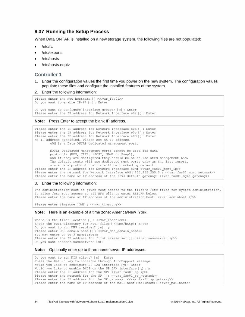
54 FlexPod Express with VMware vSphere 5.1u1 Implementation Guide © 2014 NetApp, Inc. All Rights Reserved.
9.37 Running the Setup Process
When Data ONTAP is installed on a new storage system, the following files are not populated:
/etc/rc
/etc/exports
/etc/hosts
/etc/hosts.equiv
Controller 1
1. Enter the configuration values the first time you power on the new system. The configuration values populate these files and configure the installed features of the system.
2. Enter the following information:
Please enter the new hostname []:<<var_fas01>>
Do you want to enable IPv6? [n]: Enter
Do you want to configure interface groups? [n]: Enter
Please enter the IP address for Network Interface e0a []: Enter
Note: Press Enter to accept the blank IP address.
Please enter the IP address for Network Interface e0b []: Enter
Please enter the IP address for Network Interface e0c []: Enter
Please enter the IP address for Network Interface e0d []: Enter
No IP address specified. Please set an IP address.
e0M is a Data ONTAP dedicated management port.
NOTE: Dedicated management ports cannot be used for data
protocols (NFS, CIFS, iSCSI, NDMP or Snap*),
and if they are configured they should be on an isolated management LAN.
The default route will use dedicated mgmt ports only as the last resort,
since data protocol traffic will be blocked by default.
Please enter the IP address for Network Interface e0M: <<var_fas01_mgmt_ip>>
Please enter the netmask for Network Interface e0M [255.255.255.0]: <<var_fas01_mgmt_netmask>>
Please enter the name or IP address of the IPv4 default gateway: <<var_fas01_mgmt_gateway>>
3. Enter the following information:
The administration host is given root access to the filer's /etc files for system administration.
To allow /etc root access to all NFS clients enter RETURN below.
Please enter the name or IP address of the administration host: <<var_adminhost_ip>>
Please enter timezone [GMT]: <<var_timezone>>
Note: Here is an example of a time zone: America/New_York.
Where is the filer located? []: <<var_location>>
Enter the root directory for HTTP files [/home/http]: Enter
Do you want to run DNS resolver? [n]: y
Please enter DNS domain name []: <<var_dns_domain_name>>
You may enter up to 3 nameservers
Please enter the IP address for first nameserver []: <<var_nameserver_ip>>
Do you want another nameserver? [n]:
Note: Optionally enter up to three name server IP addresses.
Do you want to run NIS client? [n]: Enter
Press the Return key to continue through AutoSupport message
Would you like to configure SP LAN interface [y]: Enter
Would you like to enable DHCP on the SP LAN interface [y]: n
Please enter the IP address for the SP: <<var_fas01_sp_ip>>
Please enter the netmask for the SP []: <<var_fas01_sp_netmask>>
Please enter the IP address for the SP gateway: <<var_fas01_sp_gateway>>
Please enter the name or IP address of the mail host [mailhost]: <<var_mailhost>>

55 FlexPod Express with VMware vSphere 5.1u1 Implementation Guide © 2014 NetApp, Inc. All Rights Reserved.
New password: <<var_admin_password>>
Retype new password <<var_admin_password>>
4. Enter the root password to log into Controller 1.
5. Reboot Controller 1.
reboot
6. When you see Press Ctrl-C for Boot Menu, enter:
Ctrl – C
7. Select 5 to boot into maintenance mode.
5
8. At the question, Continue with boot?, enter:
y
9. To verify the high-availability status of your environment, enter:
ha-config show
Note: If either component is not in high-availability mode, use the ha-config modify command to put the components in high-availability mode.
10. Reboot the controller:
halt
11. At the Loader-A prompt, enter:
autoboot
12. Log into the controller.
13. Data ONTAP assigns disks to storage controllers automatically if the disk autoassign setting is turned
on. Use the options disk.auto_assign command to verify the setting.
14. If disk autoassign is turned on, proceed with Controller 2; otherwise, continue with step 15.
15. Reboot the controller.
reboot
16. When you see Press Ctrl-C for Boot Menu, enter:
Ctrl – C
17. Select 5 to boot into maintenance mode.
5
18. When prompted Continue with boot?, enter yes (y).
19. To see how many disks are unowned, enter:
disk show -a
Note: No disks should be owned in this list.
20. Assign disks.
Note: For the small FlexPod Express configuration, <<var_#_of_disks>> should equal 9 for Controller 1.
Note: For the medium FlexPod Express configuration, <<var_#_of_disks>> should equal 21 for Controller 1.
disk assign –n <<var_#_of_disks>>
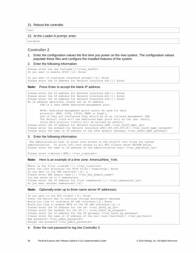
56 FlexPod Express with VMware vSphere 5.1u1 Implementation Guide © 2014 NetApp, Inc. All Rights Reserved.
21. Reboot the controller.
halt
22. At the Loader-A prompt, enter:
autoboot
Controller 2
1. Enter the configuration values the first time you power on the new system. The configuration values populate these files and configure the installed features of the system.
2. Enter the following information:
Please enter the new hostname []:<<var_fas02>>
Do you want to enable IPv6? [n]: Enter
Do you want to configure interface groups? [n]: Enter
Please enter the IP address for Network Interface e0a []: Enter
Note: Press Enter to accept the blank IP address.
Please enter the IP address for Network Interface e0b []: Enter
Please enter the IP address for Network Interface e0c []: Enter
Please enter the IP address for Network Interface e0d []: Enter
No IP address specified. Please set an IP address.
e0M is a Data ONTAP dedicated management port.
NOTE: Dedicated management ports cannot be used for data
protocols (NFS, CIFS, iSCSI, NDMP or Snap*),
and if they are configured they should be on an isolated management LAN.
The default route will use dedicated mgmt ports only as the last resort,
since data protocol traffic will be blocked by default.
Please enter the IP address for Network Interface e0M: <<var_fas02_mgmt_ip>>
Please enter the netmask for Network Interface e0M [255.255.255.0]: <<var_fas02_mgmt_netmask>>
Please enter the name or IP address of the IPv4 default gateway: <<var_fas02_mgmt_gateway>>
3. Enter the following information:
The administration host is given root access to the filer's /etc files for system
administration. To allow /etc root access to all NFS clients enter RETURN below.
Please enter the name or IP address of the administration host: <<var_adminhost_ip>>
Please enter timezone [GMT]: <<var_timezone>>
Note: Here is an example of a time zone: America/New_York.
Where is the filer located? []: <<var_location>>
Enter the root directory for HTTP files [/home/http]: Enter
Do you want to run DNS resolver? [n]: y
Please enter DNS domain name []: <<var_dns_domain_name>>
You may enter up to 3 nameservers
Please enter the IP address for first nameserver []: <<var_nameserver_ip>>
Do you want another nameserver? [n]:
Note: Optionally enter up to three name server IP addresses.
Do you want to run NIS client? [n]: Enter
Press the Return key to continue through AutoSupport message
Would you like to configure SP LAN interface [y]: Enter
Would you like to enable DHCP on the SP LAN interface [y]: n
Please enter the IP address for the SP: <<var_fas02_sp_ip>>
Please enter the netmask for the SP []: <<var_fas02_sp_netmask>>
Please enter the IP address for the SP gateway: <<var_fas02_sp_gateway>>
Please enter the name or IP address of the mail host [mailhost]: <<var_mailhost>>
New password: <<var_admin_password>>
Retype new password <<var_admin_password>>
4. Enter the root password to log into Controller 2.

57 FlexPod Express with VMware vSphere 5.1u1 Implementation Guide © 2014 NetApp, Inc. All Rights Reserved.
5. Reboot Controller 2.
reboot
6. When you see Press Ctrl-C for Boot Menu, enter:
Ctrl – C
7. Select 5 to boot into maintenance mode.
5
8. At the question, Continue with boot?, enter:
y
9. To verify the high-availability status of your environment, enter:
ha-config show
Note: If either component is not in high-availability mode, use the ha-config modify command to put the components in high-availability mode.
10. Reboot the controller:
halt
11. At the Loader-A prompt, enter:
autoboot
12. Log into the controller.
13. Data ONTAP assigns disks to storage controllers automatically if the disk autoassign setting is turned
on. Use the options disk.auto_assign command to verify the setting.
14. If disk autoassign is turned on, proceed with Controller 2; otherwise, continue with step 15.
15. Reboot the controller.
reboot
16. When you see Press Ctrl-C for Boot Menu, enter:
Ctrl – C
17. Select 5 to boot into maintenance mode.
5
18. When prompted Continue with boot?, enter yes (y).
19. To see how many disks are unowned, enter:
disk show -a
Note: No disks should be owned in this list.
20. Assign disks.
Note: For both the small and medium FlexPod Express configurations, <<var_#_of_disks>> should equal 3 for Controller 2.
disk assign –n <<var_#_of_disks>>
21. Reboot the controller.
halt
22. At the Loader-A prompt, enter:
autoboot
58 FlexPod Express with VMware vSphere 5.1u1 Implementation Guide © 2014 NetApp, Inc. All Rights Reserved.
9.38 Upgrading the Service Processor on Each Node to the Latest Release
With Data ONTAP 8.2, you must upgrade to the latest service processor firmware to take advantage of
the latest updates available for the remote management device.
1. Using a web browser, connect to http://support.netapp.com/NOW/cgi-bin/fw.
2. Navigate to the “Service Process Image for installation from the Data ONTAP prompt” page for your storage platform.
3. Proceed to the Download page for the latest release of the service processor firmware for your storage platform.
Using the instructions on this page, update the service processors on both controllers. You will need to
download the .zip file to a web server that can be reached from the management interfaces of the
controllers.
9.39 Aggregates in Data ONTAP 7-Mode
An aggregate containing the root volume is created during the Data ONTAP setup process. To create
additional aggregates, determine the aggregate name, the node on which to create it, and the number of
disks it will contain.
Controller 1
1. Run the following command to create a new aggregate:
aggr create aggr1 <<var_num_disks>>
Note: For the small ExpressPod configuration, <<var_num_disks>> should equal 5. For the medium ExpressPod configuration, <<var_num_disks>> should equal 17.
Note: You do not need to create aggr1 on Controller 2 because the aggregate is set up as a high-availability pair.
9.40 IFGRP LACP
This type of interface group requires two or more Ethernet interfaces and a switch that supports LACP, so
make sure that the switch is configured properly.
Controllers 1 and 2
1. Run the following command on the command line and also add it to the /etc/rc file so that it is activated when the system is booted:
ifgrp create lacp ifgrp0 –b ip e0a e0b e0c e0d
wrfile -a /etc/rc "ifgrp create lacp ifgrp0 –b ip e0a e0b e0c e0d"
Note: All interfaces must be in down status before being added to an interface group.
9.41 VLANs
Controllers 1 and 2
1. Enter the following command to create a VLAN interface for NFS data traffic.
vlan create ifgrp0 <<var_nfs_vlan_id>>
wrfile -a /etc/rc "vlan create ifgrp0 <<var_nfs_vlan_id>>"
9.42 IP Config
1. Run the following commands on the command line.

59 FlexPod Express with VMware vSphere 5.1u1 Implementation Guide © 2014 NetApp, Inc. All Rights Reserved.
Controller 1
ifconfig ifgrp0-<<var_nfs_vlan_id>> <<var_fas01_nfs_ip>> netmask <<var_nfs_netmask>> mtusize 9000
partner ifgrp0-<<var_nfs_vlan_id>>
wrfile –a /etc/rc " ifconfig ifgrp0-<<var_nfs_vlan_id>> << var_fas01_nfs_ip >> netmask
<<var_nfs_netmask>> mtusize 9000 partner ifgrp0-<<var_nfs_vlan_id>>"
Controller 2
ifconfig ifgrp0-<<var_nfs_vlan_id>> <<var_fas02_nfs_ip>> netmask <<var_nfs_netmask>> mtusize 9000
partner ifgrp0-<<var_nfs_vlan_id>>
wrfile –a /etc/rc " ifconfig ifgrp0-<<var_nfs_vlan_id>> << var_fas02_nfs_ip
>> netmask <<var_nfs_netmask>> mtusize 9000 partner ifgrp0-<<var_nfs_vlan_id>>"
9.43 NFSv3
Controllers 1 and 2
1. Add a license for NFS.
license add <<var_nfs_license>>
2. Set the following recommended options that enable NFS Version 3.
options nfs.tcp.enable on
options nfs.udp.enable off
options nfs.v3.enable on
3. Enable NFS.
nfs on
9.44 Active-Active Controller Configuration
Controllers 1 and 2
Enable two storage controllers to an active-active configuration.
1. Enable high availability.
options cf.mode ha
2. Reboot each storage controller.
reboot
3. Log back into both controllers.
Controller 1
1. Enable failover on controller 1 if it is not enabled already.
cf enable
9.45 Data ONTAP SecureAdmin
Secure API access to the storage controller must be configured.
Controller 1
1. Enter the following one-time command to generate the certificates used by the web services for the API.
secureadmin setup ssl
SSL Setup has already been done before. Do you want to proceed? [no] y

60 FlexPod Express with VMware vSphere 5.1u1 Implementation Guide © 2014 NetApp, Inc. All Rights Reserved.
Country Name (2 letter code) [US]: <<var_country_code>>
State or Province Name (full name) [California]: <<var_state>>
Locality Name (city, town, etc.) [Santa Clara]: <<var_city>>
Organization Name (company) [Your Company]: <<var_org>>
Organization Unit Name (division): <<var_unit>>
Common Name (fully qualified domain name) [<<var_fas01_fqdn>>]: Enter
Administrator email: <<var_storage_admin_email>>
Days until expires [5475] : Enter
Key length (bits) [512] : <<var_key_length>>
Note: NetApp recommends that your key length be 1024.
After the initialization, the certificate signing request (CSR) is available in the file /etc/keymgr/csr/secureadmin_tmp.pem.
2. Configure and enable SSL and HTTPS for API access using the following options.
options httpd.access none
options httpd.admin.enable off
options httpd.admin.ssl.enable on
options ssl.enable on
Controller 2
1. Enter the following one-time command to generate the certificates used by the web services for the API.
secureadmin setup ssl
SSL Setup has already been done before. Do you want to proceed? [no] y
Country Name (2 letter code) [US]: <<var_country_code>>
State or Province Name (full name) [California]: <<var_state>>
Locality Name (city, town, etc.) [Santa Clara]: <<var_city>>
Organization Name (company) [Your Company]: <<var_org>>
Organization Unit Name (division): <<var_unit>>
Common Name (fully qualified domain name) [<<var_fas02_fqdn>>]: Enter
Administrator email: <<var_storage_admin_email>>
Days until expires [5475] : Enter
Key length (bits) [512] : <<var_key_length>>
Note: NetApp recommends that your key length be 1024.
After the initialization, the CSR is available in the file /etc/keymgr/csr/secureadmin_tmp.pem.
2. Configure and enable SSL and HTTPS for API access using the following options.
options httpd.access none
options httpd.admin.enable off
options httpd.admin.ssl.enable on
options ssl.enable on
9.46 Secure Shell
SSH must be configured and enabled.
Controllers 1 and 2
1. Use the following one-time command to generate host keys.
secureadmin disable ssh
secureadmin setup –f -q ssh 768 512 1024
2. Use the following options to configure and enable SSH.
options ssh.idle.timeout 60
options autologout.telnet.timeout 5
61 FlexPod Express with VMware vSphere 5.1u1 Implementation Guide © 2014 NetApp, Inc. All Rights Reserved.
9.47 SNMP
Controllers 1 and 2
1. Run the following commands to configure SNMP basic information, such as local and contact
information. When the system is polled, this information is displayed as the sysLocation and
sysContact variables in SNMP.
snmp contact “<<var_snmp_contact>>”
snmp location “<<var_snmp_location>>”
snmp init 1
options snmp.enable on
2. Configure SNMP traps to send them to remote hosts, such as a NetApp DFM server or another fault management system.
snmp traphost add <<var_snmp_trap_server_fqdn>>
9.48 SNMPv1
Controllers 1 and 2
1. Set the shared secret plain-text password, which is called a community.
snmp community delete all
snmp community add ro <<var_snmp_community>>
Note: Use the delete all command with caution. If community strings are used for other monitoring products, the delete all command will remove them.
9.49 SNMPv3
SNMPv3 requires a user to be defined and configured for authentication.
Controllers 1 and 2
1. Create a user called snmpv3user.
useradmin role add snmp_requests -a login-snmp
useradmin group add snmp_managers -r snmp_requests
useradmin user add snmpv3user -g snmp_managers
New Password: <<var_password>>
Retype new password: <<var_password>>
9.50 AutoSupport HTTPS
AutoSupport sends support summary information to NetApp through HTTPS.
Controllers 1 and 2
1. Run the following commands to configure AutoSupport:
options autosupport.noteto <<var_storage_admin_email>>
9.51 Security Best Practices
Apply the following commands according to local security policies.
Controllers 1 and 2
1. Run the following commands to enhance security on the storage controller:
options rsh.access none

62 FlexPod Express with VMware vSphere 5.1u1 Implementation Guide © 2014 NetApp, Inc. All Rights Reserved.
options webdav.enable off
options security.passwd.rules.maximum 14
options security.passwd.rules.minimum.symbol 1
options security.passwd.lockout.numtries 6
options autologout.console.timeout 5
9.52 Enabling Network Data Management Protocol
Controllers 1 and 2
1. Run the following commands to enable Network Data Management Protocol (NDMP).
options ndmpd.enable on
9.53 Creating NetApp FlexVol Volumes
Controller 1
1. Create two volumes on Controller 1 using the following commands:
vol create infra_swap –s none aggr1 100g
snap reserve infra_swap 0
snap sched infra_swap 0 0 0
vol create infra_datastore_1 –s none aggr1 500g
snap reserve infra_datastore_1 0
sis on /vol/ infra_datastore_1
9.54 NFS Exports
Controller 1
1. Use the following commands to create NFS exports:
exportfs –p
sec=sys,rw=<<var_esxi1_nfs_ip>>:<<var_esxi2_nfs_ip>>:<<var_esxi3_nfs_ip>>:<<var_esxi4_nfs_ip>>,ro
ot=<<var_esxi1_nfs_ip>>:<<var_esxi2_nfs_ip>>:<<var_esxi3_nfs_ip>>:<<var_esxi4_nfs_ip>>,nosuid
/vol/infra_swap
exportfs –p
sec=sys,rw=<<var_esxi1_nfs_ip>>:<<var_esxi2_nfs_ip>>:<<var_esxi3_nfs_ip>>:<<var_esxi4_nfs_ip>>,ro
ot=<<var_esxi1_nfs_ip>>:<<var_esxi2_nfs_ip>>:<<var_esxi3_nfs_ip>>:<<var_esxi4_nfs_ip>>,nosuid
/vol/infra_datastore_1
9.55 Enabling Cisco Discovery Protocol
Use the following steps to enable Cisco Discovery Protocol on Controller 1 and 2.
Controllers 1 and 2
1. Enable Cisco Discovery Protocol.
options cdpd.enable on
10 Cisco UCS C-Series Rack Servers Deployment Procedure
This section provides detailed steps for configuring a Cisco UCS C-Series standalone server for use in
either the small or medium FlexPod Express configurations.
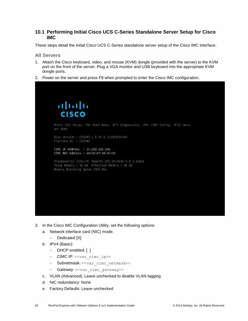
63 FlexPod Express with VMware vSphere 5.1u1 Implementation Guide © 2014 NetApp, Inc. All Rights Reserved.
10.1 Performing Initial Cisco UCS C-Series Standalone Server Setup for Cisco IMC
These steps detail the initial Cisco UCS C-Series standalone server setup of the Cisco IMC interface.
All Servers
1. Attach the Cisco keyboard, video, and mouse (KVM) dongle (provided with the server) to the KVM port on the front of the server. Plug a VGA monitor and USB keyboard into the appropriate KVM dongle ports.
2. Power on the server and press F8 when prompted to enter the Cisco IMC configuration.
3. In the Cisco IMC Configuration Utility, set the following options:
a. Network interface card (NIC) mode:
Dedicated [X]
b. IPV4 (Basic):
DHCP enabled: [ ]
CIMC IP: <<var_cimc_ip>>
Subnetmask: <<var_cimc_netmask>>
Gateway: <<var_cimc_gateway>>
c. VLAN (Advanced): Leave unchecked to disable VLAN tagging
d. NIC redundancy: None
e. Factory Defaults: Leave unchecked
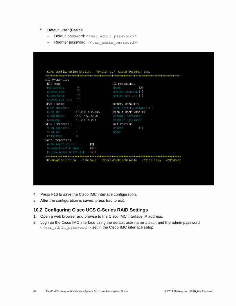
64 FlexPod Express with VMware vSphere 5.1u1 Implementation Guide © 2014 NetApp, Inc. All Rights Reserved.
f. Default User (Basic):
Default password: <<var_admin_password>>
Reenter password: <<var_admin_password>>
4. Press F10 to save the Cisco IMC interface configuration.
5. After the configuration is saved, press Esc to exit.
10.2 Configuring Cisco UCS C-Series RAID Settings
1. Open a web browser and browse to the Cisco IMC interface IP address.
2. Log into the Cisco IMC interface using the default user name admin and the admin password
<<var_admin_password>> set in the Cisco IMC interface setup.

65 FlexPod Express with VMware vSphere 5.1u1 Implementation Guide © 2014 NetApp, Inc. All Rights Reserved.
3. After you are successfully logged in, click the Server tab and then choose Summary. Choose Launch KVM Console. The virtual KVM window will open.
4. Select Virtual Media at the top of the window.
5. Click Add Image.
6. Browse to the location of the Server Configuration Utility ISO image and select it. Click Open.
7. Select the Mapped checkbox next to the selected ISO image to map the image to the server.
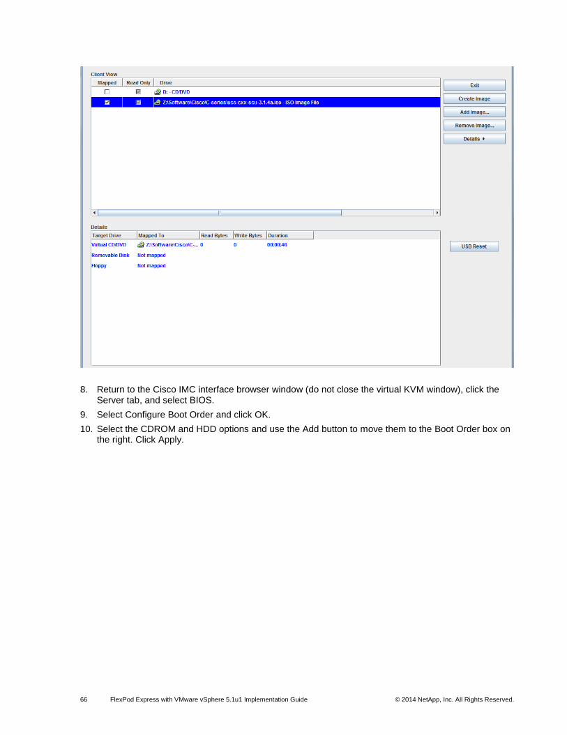
66 FlexPod Express with VMware vSphere 5.1u1 Implementation Guide © 2014 NetApp, Inc. All Rights Reserved.
8. Return to the Cisco IMC interface browser window (do not close the virtual KVM window), click the Server tab, and select BIOS.
9. Select Configure Boot Order and click OK.
10. Select the CDROM and HDD options and use the Add button to move them to the Boot Order box on the right. Click Apply.
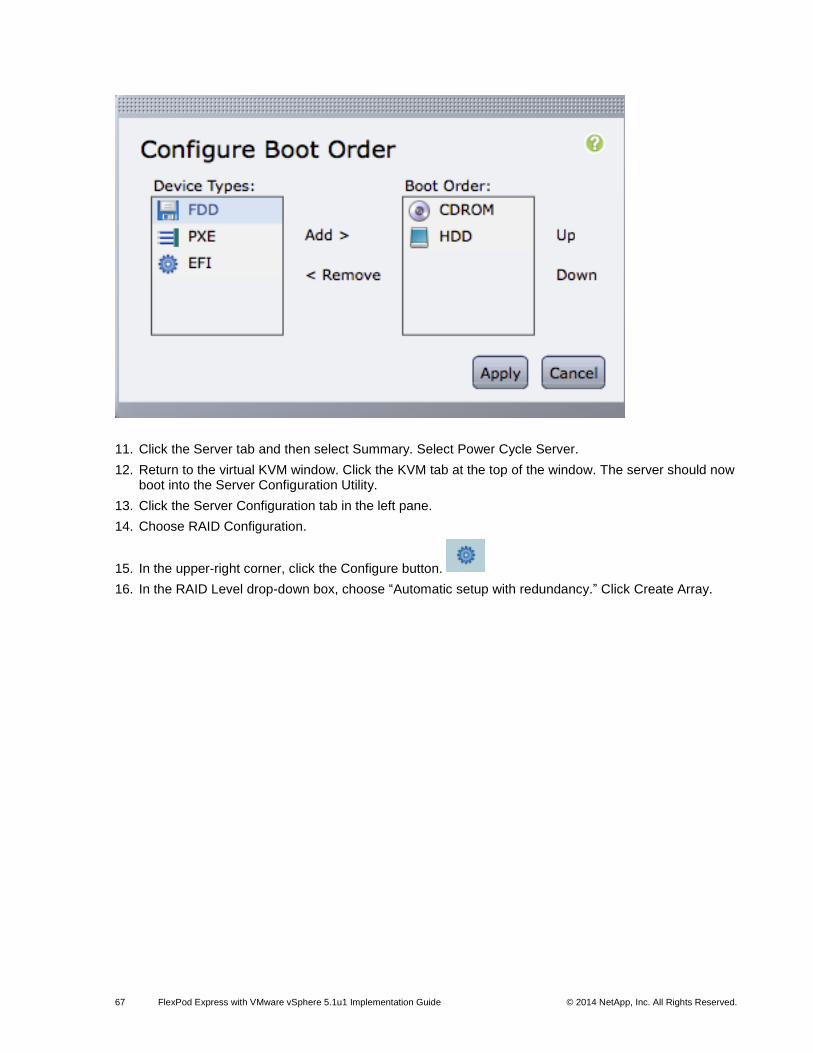
67 FlexPod Express with VMware vSphere 5.1u1 Implementation Guide © 2014 NetApp, Inc. All Rights Reserved.
11. Click the Server tab and then select Summary. Select Power Cycle Server.
12. Return to the virtual KVM window. Click the KVM tab at the top of the window. The server should now boot into the Server Configuration Utility.
13. Click the Server Configuration tab in the left pane.
14. Choose RAID Configuration.
15. In the upper-right corner, click the Configure button.
16. In the RAID Level drop-down box, choose “Automatic setup with redundancy.” Click Create Array.
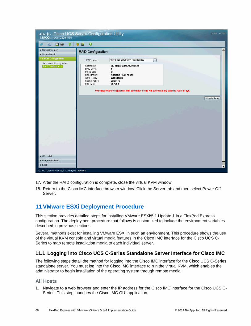
68 FlexPod Express with VMware vSphere 5.1u1 Implementation Guide © 2014 NetApp, Inc. All Rights Reserved.
17. After the RAID configuration is complete, close the virtual KVM window.
18. Return to the Cisco IMC interface browser window. Click the Server tab and then select Power Off Server.
11 VMware ESXi Deployment Procedure
This section provides detailed steps for installing VMware ESXi\5.1 Update 1 in a FlexPod Express
configuration. The deployment procedure that follows is customized to include the environment variables
described in previous sections.
Several methods exist for installing VMware ESXi in such an environment. This procedure shows the use
of the virtual KVM console and virtual media features in the Cisco IMC interface for the Cisco UCS C-
Series to map remote installation media to each individual server.
11.1 Logging into Cisco UCS C-Series Standalone Server Interface for Cisco IMC
The following steps detail the method for logging into the Cisco IMC interface for the Cisco UCS C-Series
standalone server. You must log into the Cisco IMC interface to run the virtual KVM, which enables the
administrator to begin installation of the operating system through remote media.
All Hosts
1. Navigate to a web browser and enter the IP address for the Cisco IMC interface for the Cisco UCS C-Series. This step launches the Cisco IMC GUI application.
69 FlexPod Express with VMware vSphere 5.1u1 Implementation Guide © 2014 NetApp, Inc. All Rights Reserved.
2. Log into the Cisco IMC GUI with the admin user name and credentials.
3. In the main menu, select the Server tab.
4. Click Launch KVM Console.
11.2 Setting Up the VMware ESXi Installation
This section details the steps required to prepare the server for OS installation.
All Hosts
1. From the virtual KVM console, select the Virtual Media tab.
2. Select Add Image in the right pane.
3. Browse to the VMware ESXi 5.1 installer ISO image file and click Open.
4. Map the image that you just added by selecting Mapped.
5. To boot the server, select the KVM tab.
6. On the Cisco IMC interface Summary tab, select Power On Server and then click OK.
11.3 Installing VMware ESXi
The following steps show how to install VMware ESXi on each host’s local RAID drive.
All Hosts
1. When it boots, the machine detects the presence of the VMware ESXi installation media.
2. Select the VMware ESXi Installer from the menu that appears.
3. After the installer has finished loading, press Enter to continue with the installation.
4. After reading the end-user license agreement (EULA), press F11 to accept the agreement and continue with the installation.
5. Select the local RAID drive that was set up previously as the installation location for VMware ESXi and press Enter to continue with the installation.
6. Select the appropriate keyboard layout and press Enter to continue.
7. Enter and confirm the root password and press Enter to continue.
8. The installer warns you that existing partitions will be removed on the volume. Press F11 to continue with the installation.
9. After the installation is complete, clear the Mapped option to unmap the VMware ESXi installation image on the virtual media tab of the KVM console to make sure that the server reboots into VMware ESXi and not the installer.
10. The Virtual Media window may warn you that it is preferable to eject the media from the guest system. Because you cannot do this (and the media is read-only), unmap the image anyway by clicking Yes.
11. On the KVM tab, press Enter to reboot the server.
11.4 Setting Up Management Networking for the VMware ESXi Hosts
The following steps show how to add the management network for each VMware ESXi host.
All Hosts
1. After the server is finished rebooting, press F2 to select the option to customize the system.
2. Log in with root as the login name and the root password previously entered during installation.
3. Select the Configure Management Network option.
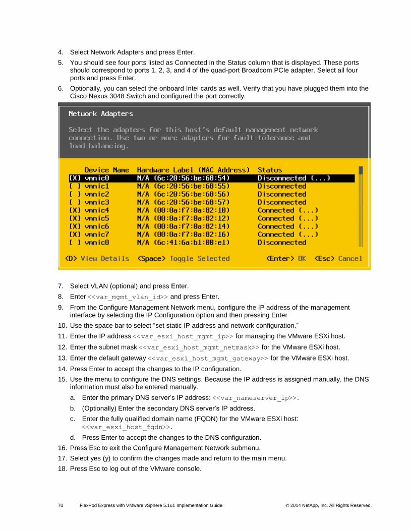
70 FlexPod Express with VMware vSphere 5.1u1 Implementation Guide © 2014 NetApp, Inc. All Rights Reserved.
4. Select Network Adapters and press Enter.
5. You should see four ports listed as Connected in the Status column that is displayed. These ports should correspond to ports 1, 2, 3, and 4 of the quad-port Broadcom PCIe adapter. Select all four ports and press Enter.
6. Optionally, you can select the onboard Intel cards as well. Verify that you have plugged them into the Cisco Nexus 3048 Switch and configured the port correctly.
7. Select VLAN (optional) and press Enter.
8. Enter <<var_mgmt_vlan_id>> and press Enter.
9. From the Configure Management Network menu, configure the IP address of the management interface by selecting the IP Configuration option and then pressing Enter
10. Use the space bar to select “set static IP address and network configuration.”
11. Enter the IP address <<var_esxi_host_mgmt_ip>> for managing the VMware ESXi host.
12. Enter the subnet mask <<var_esxi_host_mgmt_netmask>> for the VMware ESXi host.
13. Enter the default gateway <<var_esxi_host_mgmt_gateway>> for the VMware ESXi host.
14. Press Enter to accept the changes to the IP configuration.
15. Use the menu to configure the DNS settings. Because the IP address is assigned manually, the DNS information must also be entered manually.
a. Enter the primary DNS server’s IP address: <<var_nameserver_ip>>.
b. (Optionally) Enter the secondary DNS server’s IP address.
c. Enter the fully qualified domain name (FQDN) for the VMware ESXi host:
<<var_esxi_host_fqdn>>.
d. Press Enter to accept the changes to the DNS configuration.
16. Press Esc to exit the Configure Management Network submenu.
17. Select yes (y) to confirm the changes made and return to the main menu.
18. Press Esc to log out of the VMware console.
71 FlexPod Express with VMware vSphere 5.1u1 Implementation Guide © 2014 NetApp, Inc. All Rights Reserved.
11.5 Downloading the VMware vSphere Client and Remote Command Line
The following steps provide details for downloading the VMware vSphere Client and installing the remote
command line.
1. Open a web browser on a management workstation and navigate to the management IP address of one of the VMware ESXi hosts.
2. Download and install both the VMware vSphere Client and the Microsoft Windows version of the VMware vSphere remote command line.
11.6 Logging into the VMware ESXi Hosts Using the VMware vSphere Client
These steps provide details for logging into each VMware ESXi host using the VMware vSphere Client.
All Hosts
1. Open the recently downloaded VMware vSphere Client and enter the IP address of the host to which
are you trying to connect: <<var_esxi_host_mgmt_ip>>.
2. Enter root for the user name.
3. Enter the root password.
4. Click Login to connect.
11.7 Setting Up VMkernel Ports and the Virtual Switch
The following steps provide details for setting up VMkernel ports and virtual switches.
All Hosts
1. In the VMware vSphere Client, select the host in the left pane.
2. Select the Configuration tab.
3. Select the Networking link in the Hardware box.
4. Select the Properties link in the right field on vSwitch0.
5. Select the vSwitch configuration and click Edit.
6. On the General tab, change the MTU value to 9000.
7. On the NIC Teaming tab, change all adapters so that they are active adapters by clicking each individual adapter and using the Move Up button at the right.
8. Close the properties for vSwitch0 by clicking OK.
9. Select the Management Network configuration and click Edit.
10. Verify that the Management Traffic checkbox is checked.
11. Finalize the edits for the management network by clicking OK.
12. Select the VM Network configuration and click Edit.
13. Change the Network label to MGMT-Network and enter <<var_mgmt_vlan_id>> in the VLAN ID
(Optional) field.
14. Finalize the edits for the virtual machine network by clicking OK.
15. Click Add to add a network element.
16. Select Virtual Machine.
17. Enter NFS-Network for Network Label and <<var_nfs_vlan_id>> for VLAN ID.
18. Click Next.
19. Click Finish.
72 FlexPod Express with VMware vSphere 5.1u1 Implementation Guide © 2014 NetApp, Inc. All Rights Reserved.
20. Click Add to add a network element.
21. Select the VMkernel radio button and click Next.
22. Change the Network label to VMkernel-NFS and enter <<var_nfs_vlan_id>> in the VLAN ID
(Optional) field.
23. Continue with NFS VMkernel creation by clicking Next.
24. Enter <<var_esxi_host_nfs_ip>> <<var_esxi_host_nfs_netmask>> for the NFS VLAN
interface for the host.
25. Continue with the NFS VMkernel creation by clicking Next.
26. Finalize the creation of the NFS VMkernel interface by clicking Finish.
27. Select the VMkernel-NFS configuration and click Edit.
28. Change the MTU value to 9000.
29. Finalize the edits for VMkernel-NFS Network by clicking OK.
30. Click Add to add a network element.
31. Select the VMkernel radio button and click Next.
32. Change the Network label to VMkernel-vMotion and enter <<var_vmotion_vlan_id>> in the
VLAN ID (Optional) field.
33. Select the checkbox to use this port group for vMotion.
34. Continue with the vMotion VMkernel creation by clicking Next.
35. Enter <<var_esxi_host_vmotion_ip>> <<var_esxi_host_vmotion_netmask>> for the
vMotion VLAN interface for the host.
36. Continue with the vMotion VMkernel creation by clicking Next.
37. Finalize the creation of the vMotion VMkernel interface by clicking Finish.
38. Select the VMkernel-vMotion configuration and click Edit.
39. Change the MTU value to 9000.
40. Finalize the edits for the VMkernel-vMotion network by clicking OK.
41. Click Add to add a network element.
42. Leave “Virtual Machine connection type” selected and click Next.
43. Change the Network label to VM-Network and enter << var_vmtraffic_vlan_id >> in the VLAN
ID (Optional) field.
44. Click Next.
45. Click Finish.
46. Close the dialog box to finalize the VMware ESXi host network setup.
11.8 Mounting the Required Datastores
This step provides details for mounting the required datastores.
All Hosts
1. On each VMware vSphere Client, select the host in the left pane.
2. Select the Configuration tab to enable configurations.
3. Click the Storage link in the Hardware box.
4. In the right panel, in the Datastore section, click Add Storage.
5. The Add Storage wizard appears. Select the Network File System button and click Next.
6. Enter the server IP address:
73 FlexPod Express with VMware vSphere 5.1u1 Implementation Guide © 2014 NetApp, Inc. All Rights Reserved.
For clustered Data ONTAP deployments, enter <<var_fas01_nfs_lif_ip>>.
For 7-Mode Data ONTAP deployments, enter <<var_fas01_nfs_ip>>.
7. Enter the path for the NFS export:
For clustered Data ONTAP deployments, enter /infra_datastore_1.
For 7-Mode Data ONTAP deployments, enter /vol/infra_datastore_1.
8. Verify that the “Mount NFS read only” checkbox is cleared.
9. Enter the datastore name: infra_datastore_1.
10. Continue with NFS datastore creation by clicking Next.
11. Finalize the creation of the NFS datastore by clicking Finish.
12. In the right panel, in the Datastore section, click Add Storage.
13. The Add Storage wizard appears. Select the Network File System button and click Next.
14. Enter the server IP address:
For clustered Data ONTAP deployments, enter <<var_fas01_nfs_lif_ip>>.
For 7-Mode Data ONTAP deployments, enter <<var_fas01_nfs_ip>>.
15. Enter the path for the NFS export:
a. For clustered Data ONTAP deployments, enter /infra_swap.
b. For 7-Mode Data ONTAP deployments, enter /vol/infra_swap.
16. Verify that the “Mount NFS read only” checkbox is cleared.
17. Enter the datastore name: infra_swap.
18. Continue with NFS datastore creation by clicking Next.
19. Finalize the creation of the NFS datastore by clicking Finish.
11.9 Moving the Virtual Machine Swapfile Location
These steps provide details for moving the virtual machine swapfile location.
All Hosts
1. Select the host in the left pane in VMware vSphere Client.
2. Select the Configuration tab to enable configuration.
3. Click the Virtual Machine Swapfile Location link in the Software box.
4. Click Edit in the right pane.
5. Select the “Store the swapfile in a swapfile datastore selected below” button.
6. Select the infra_swap datastore.
7. Finalize the movement of the swapfile location by clicking OK.
12 VMware vCenter 5.1 Update 1 Deployment Procedure
The steps in this section provide detailed instructions for installing VMware vCenter 5.1 Update 1 in a
FlexPod environment.
12.1 Building a VMware vCenter Virtual Machine
One Server Only
1. Use the VMware vSphere Client to log into a VMware ESXi host.
74 FlexPod Express with VMware vSphere 5.1u1 Implementation Guide © 2014 NetApp, Inc. All Rights Reserved.
2. In the VMware vSphere Client, select the host in the left pane.
3. Right-click the host and select New Virtual Machine.
4. Select Custom and click Next.
5. Enter a name for the virtual machine. Click Next.
6. Select infra_datastore_1. Click Next.
7. Select Virtual Machine Version: 8. Click Next.
8. Verify that the Microsoft Windows option and Microsoft® Windows Server 2008
® R2 (64-bit) version
are selected. Click Next.
9. Select two virtual sockets and one core per virtual socket. Click Next.
10. Select 4GB of memory. Click Next.
11. Select two NICs total.
12. For NIC 1, select the MGMT-Network option and the VMXNET 3 adapter.
13. For NIC 2, select the NFS-Network option and the VMXNET 3 adapter.
14. Click Next.
15. Keep the LSI Logic SAS option for the SCSI controller selected. Click Next.
16. Keep the Create a New Virtual Disk option selected. Click Next.
17. Make the disk size at least 60 GB. Click Next.
18. Click Next.
19. Select the checkbox for Edit the Virtual Machine Settings Before Completion. Click Continue.
20. Click the Options tab.
21. Select Boot Options.
22. Select the Force BIOS Setup checkbox.
23. Click Finish.
24. In the left pane, expand the host field by clicking the plus sign (+).
25. Right-click the newly created vCenter virtual machine and click Open Console.
26. Click the third button (green right arrow) to power on the virtual machine.
27. Click the ninth button (CD with a wrench) to map the Microsoft Windows Server 2008 R2 SP1 ISO, and then select Connect to ISO Image on Local Disk.
28. Navigate to the Microsoft Windows Server 2008 R2 SP1 ISO, select it, and click Open.
29. Click in the BIOS Setup Utility window and use the right arrow key to navigate to the Boot menu. Use the down arrow key to select CD-ROM Drive. Press the plus (+) key twice to move CD-ROM Drive to the top of the list. Press F10 and Enter to save the selection and exit the BIOS Setup Utility.
30. The Microsoft Windows Installer boots. Select the appropriate language, time and currency formats, and keyboard. Click Next.
31. Click Install Now.
32. Make sure that the Microsoft Windows Server 2008 R2 Standard (Full Installation) option is selected. Click Next.
33. Read and accept the license terms and click Next.
34. Select Custom (advanced). Make sure that Disk 0 Unallocated Space is selected. Click Next to allow the Microsoft Windows installation to complete.
35. After the Microsoft Windows installation is complete and the virtual machine has rebooted, click OK to set the Administrator password.
36. Enter and confirm the Administrator password and click the blue arrow to log in. Click OK to confirm the password change.
75 FlexPod Express with VMware vSphere 5.1u1 Implementation Guide © 2014 NetApp, Inc. All Rights Reserved.
37. After logging into the virtual machine desktop, from the virtual machine console window, select the virtual machine menu. Under Guest, select Install/Upgrade VMware Tools. Click OK.
38. If you are prompted to eject the Microsoft Windows installation media before running the setup for the VMware tools, click OK; then click OK again.
39. In the dialog box, select “Run setup64.exe.”
40. In the VMware Tools installer window, click Next.
41. Verify that Typical is selected and click Next.
42. Click Install.
43. If you are prompted to trust software from VMware, select the checkbox to always trust VMware software; then click Install.
44. Click Finish.
45. Click Yes to restart the virtual machine.
46. After the reboot is complete, select the virtual machine menu. Under Guest, select Send Ctrl+Alt+Del and then enter the password to log into the virtual machine.
47. Set the time zone for the virtual machine, IP address, gateway, and host name.
Note: A reboot is required.
48. If necessary, activate Microsoft Windows.
49. Log back into the virtual machine and download and install all required Microsoft Windows updates.
Note: This process requires several reboots.
50. From the Microsoft Windows task bar, click Server Manager. Click Configure Remote Desktop.
51. In the System Properties window, select “Allow connections from computers running any version of Remote Desktop(less secure).” Click OK.
52. Log back into the VMware vCenter virtual machine and add the virtual machine to the Microsoft Windows Active Directory domain.
Note: A reboot is required.
12.2 Installing VMware vCenter Server
vCenter Server VM
To install VMware vCenter Server on the VMware vCenter Server virtual machine, complete the following
steps:
1. In the VMware vCenter Server console, click the ninth button (CD with a wrench) to map the VMware vCenter ISO and select Connect to ISO Image on Local Disk.
2. Navigate to the VMware vCenter 5.1 Update 1 (VIMSetup) ISO, select it, and click Open.
3. In the dialog box, click “Run autorun.exe.”
4. In the VMware vCenter Installer window, make sure that VMware vCenter Simple Install is selected and click Install.

76 FlexPod Express with VMware vSphere 5.1u1 Implementation Guide © 2014 NetApp, Inc. All Rights Reserved.
5. Click Next to install VMware vCenter Single Sign On.
6. Click Next.
7. Accept the terms of the license agreement and click Next.
8. Enter and confirm <<var_admin_password>> for admin@System-Domain. Click Next.
9. Click Next.
10. Select “Install a local Microsoft SQL Server 2008 R2 Express instance” and click Next.
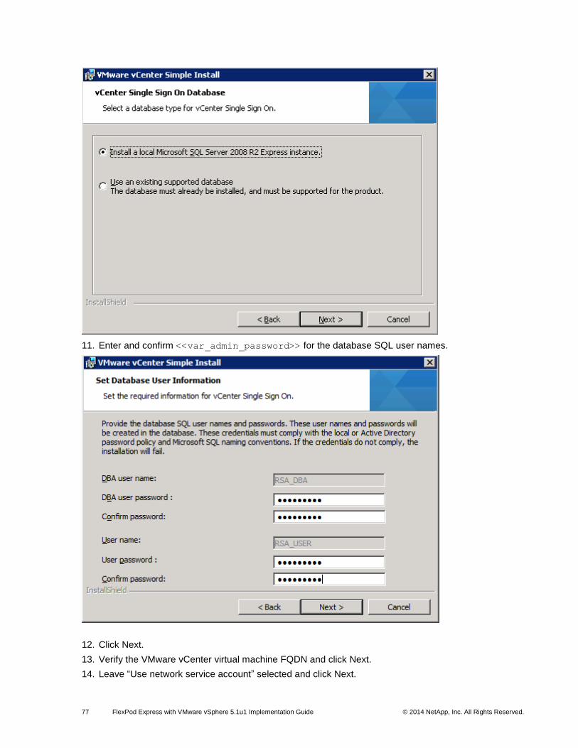
77 FlexPod Express with VMware vSphere 5.1u1 Implementation Guide © 2014 NetApp, Inc. All Rights Reserved.
11. Enter and confirm <<var_admin_password>> for the database SQL user names.
12. Click Next.
13. Verify the VMware vCenter virtual machine FQDN and click Next.
14. Leave “Use network service account” selected and click Next.
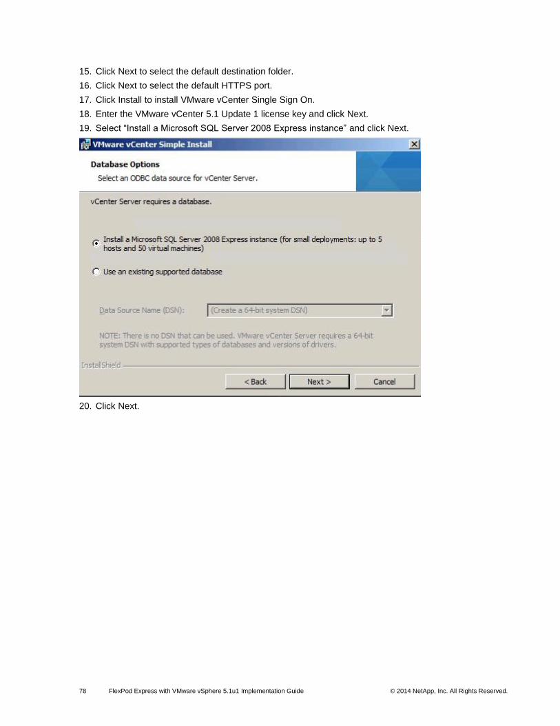
78 FlexPod Express with VMware vSphere 5.1u1 Implementation Guide © 2014 NetApp, Inc. All Rights Reserved.
15. Click Next to select the default destination folder.
16. Click Next to select the default HTTPS port.
17. Click Install to install VMware vCenter Single Sign On.
18. Enter the VMware vCenter 5.1 Update 1 license key and click Next.
19. Select “Install a Microsoft SQL Server 2008 Express instance” and click Next.
20. Click Next.
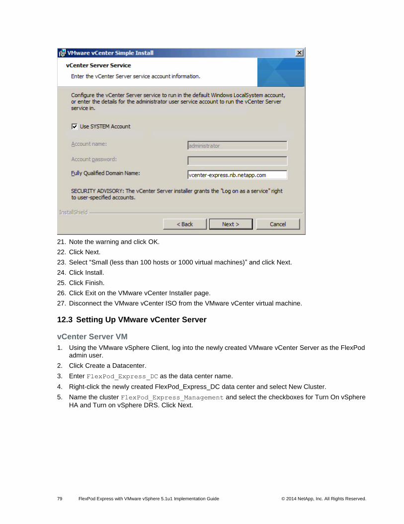
79 FlexPod Express with VMware vSphere 5.1u1 Implementation Guide © 2014 NetApp, Inc. All Rights Reserved.
21. Note the warning and click OK.
22. Click Next.
23. Select “Small (less than 100 hosts or 1000 virtual machines)” and click Next.
24. Click Install.
25. Click Finish.
26. Click Exit on the VMware vCenter Installer page.
27. Disconnect the VMware vCenter ISO from the VMware vCenter virtual machine.
12.3 Setting Up VMware vCenter Server
vCenter Server VM
1. Using the VMware vSphere Client, log into the newly created VMware vCenter Server as the FlexPod admin user.
2. Click Create a Datacenter.
3. Enter FlexPod_Express_DC as the data center name.
4. Right-click the newly created FlexPod_Express_DC data center and select New Cluster.
5. Name the cluster FlexPod_Express_Management and select the checkboxes for Turn On vSphere
HA and Turn on vSphere DRS. Click Next.
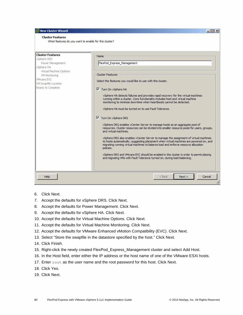
80 FlexPod Express with VMware vSphere 5.1u1 Implementation Guide © 2014 NetApp, Inc. All Rights Reserved.
6. Click Next.
7. Accept the defaults for vSphere DRS. Click Next.
8. Accept the defaults for Power Management. Click Next.
9. Accept the defaults for vSphere HA. Click Next.
10. Accept the defaults for Virtual Machine Options. Click Next.
11. Accept the defaults for Virtual Machine Monitoring. Click Next.
12. Accept the defaults for VMware Enhanced vMotion Compatibility (EVC). Click Next.
13. Select “Store the swapfile in the datastore specified by the host.” Click Next.
14. Click Finish.
15. Right-click the newly created FlexPod_Express_Management cluster and select Add Host.
16. In the Host field, enter either the IP address or the host name of one of the VMware ESXi hosts.
17. Enter root as the user name and the root password for this host. Click Next.
18. Click Yes.
19. Click Next.
81 FlexPod Express with VMware vSphere 5.1u1 Implementation Guide © 2014 NetApp, Inc. All Rights Reserved.
20. Select “Assign a New License Key to this host.” Select Enter Key and enter a VMware vSphere license key.
21. Click OK and then click Next.
22. Click Next.
23. Click Next.
24. Click Finish. The host should now be added to the cluster.
25. Using the preceding instructions, add the remaining individual VMware ESXi hosts to the cluster.
Note: Two VMware ESXi hosts will be added to the cluster for the small FlexPod Express configuration. Four VMware ESXi hosts will added to the cluster for the medium FlexPod Express configuration.
12.4 Setting Up a Microsoft Windows Template
To create a Microsoft Windows template, complete the following steps.
1. To create a Microsoft Windows virtual machine, perform steps 1 through 51 in the section 12.1.
2. Log into the VMware vCenter virtual machine and right-click the virtual machine that was created in step 1. Choose Template > Clone to Template.
3. Enter the name w2k8-template for the clone virtual machine.
4. Select the cluster FlexPod_Express_DC as the target host or cluster on which to run the virtual machine. Click Next.
5. Select infra_datastore_1. Click Next.
6. Click Finish.
13 NetApp Virtual Storage Console 4.2.1 Deployment Procedure
13.1 NetApp VSC 4.2.1 Preinstallation Considerations
The following licenses are required for NetApp VSC on storage systems that run clustered Data ONTAP
8.2:
Protocol licenses (NFS and FCP)
NetApp FlexClone (for provisioning and cloning only)
NetApp SnapRestore (for backup and recovery)
NetApp SnapManager suite
13.2 Installing NetApp VSC 4.2.1
To install the NetApp VSC 4.2.1 software, complete the following steps:
1. Log into the VMware vCenter virtual machine.
2. Configure jumbo frames on the network adapter in the NFS network. Open Server Manager and click
View Network Connections. Right-click the network connection in the <<var_nfs_vlan_id>> VLAN
and select Properties. Click Configure. Select the Advanced tab. Select the Jumbo Packet property and use the pull-down menu to select Jumbo 9000. Click OK. Close the Network Connections window and close Server Manager.
3. Download the x64 version of the NetApp VSC 4.2.1 from the NetApp Support site.
4. Right-click the file downloaded in step 3 and select Run as Administrator.
5. On the Installation wizard Welcome page, click Next.
6. Select the checkbox to accept the message. Click Next.
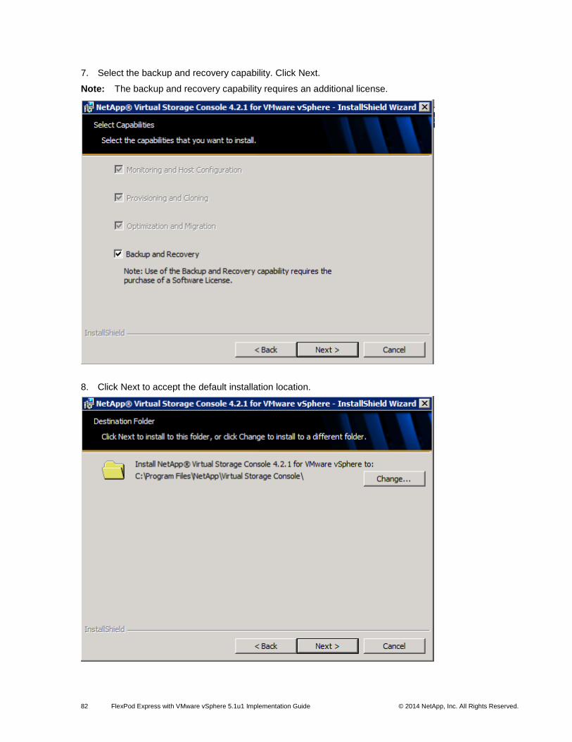
82 FlexPod Express with VMware vSphere 5.1u1 Implementation Guide © 2014 NetApp, Inc. All Rights Reserved.
7. Select the backup and recovery capability. Click Next.
Note: The backup and recovery capability requires an additional license.
8. Click Next to accept the default installation location.

83 FlexPod Express with VMware vSphere 5.1u1 Implementation Guide © 2014 NetApp, Inc. All Rights Reserved.
9. Click Install.
10. Click Finish.
13.3 Registering NetApp VSC with VMware vCenter Server
To register the NetApp VSC with the VMware vCenter Server, complete the following steps.
1. A browser window with the registration URL opens automatically when the installation phase is complete.
2. Click “Continue to this website (not recommended).”
3. In the Plug-in Service Information section, from the drop-down list, select the local IP address that the VMware vCenter Server uses to access the NetApp VSC server from the drop-down list.
4. In the VMware vCenter Server Information section, enter the host name or IP address, user name (FlexPod admin user), and user password for the VMware vCenter Server. Click Register to complete the registration.

84 FlexPod Express with VMware vSphere 5.1u1 Implementation Guide © 2014 NetApp, Inc. All Rights Reserved.
13.4 Discovering and Adding Storage Resources
To discover storage resources for the Monitoring and Host Configuration and the Provisioning and
Cloning capabilities, complete the following steps.
1. Using the VMware vSphere Client, log into the VMware vCenter Server as the FlexPod admin user. If the VMware vSphere Client was previously opened, close it and then reopen it.
2. If an SSL certificate warning from the NetApp VSC is displayed, select the checkbox to install the certificate and then click Ignore.
3. Select the Home tab at the left of the VMware vSphere Client window.
4. Under Solutions and Applications, click the NetApp icon.
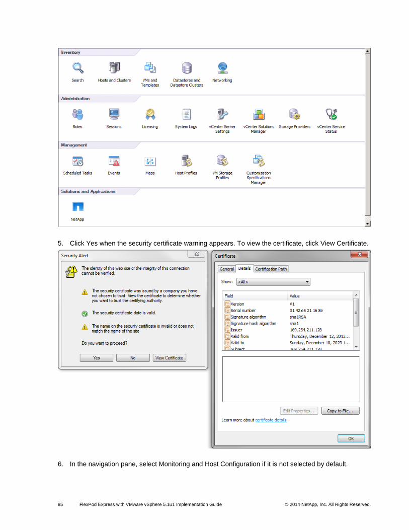
85 FlexPod Express with VMware vSphere 5.1u1 Implementation Guide © 2014 NetApp, Inc. All Rights Reserved.
5. Click Yes when the security certificate warning appears. To view the certificate, click View Certificate.
6. In the navigation pane, select Monitoring and Host Configuration if it is not selected by default.
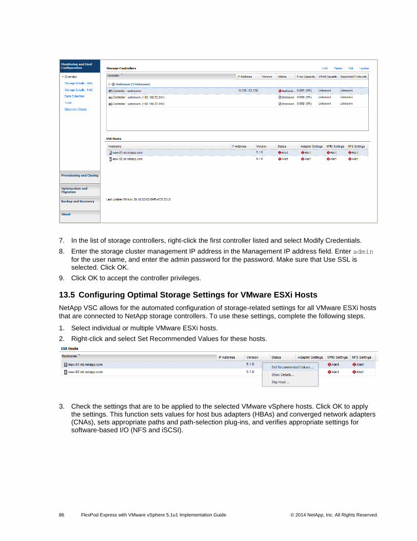
86 FlexPod Express with VMware vSphere 5.1u1 Implementation Guide © 2014 NetApp, Inc. All Rights Reserved.
7. In the list of storage controllers, right-click the first controller listed and select Modify Credentials.
8. Enter the storage cluster management IP address in the Management IP address field. Enter admin
for the user name, and enter the admin password for the password. Make sure that Use SSL is selected. Click OK.
9. Click OK to accept the controller privileges.
13.5 Configuring Optimal Storage Settings for VMware ESXi Hosts
NetApp VSC allows for the automated configuration of storage-related settings for all VMware ESXi hosts
that are connected to NetApp storage controllers. To use these settings, complete the following steps.
1. Select individual or multiple VMware ESXi hosts.
2. Right-click and select Set Recommended Values for these hosts.
3. Check the settings that are to be applied to the selected VMware vSphere hosts. Click OK to apply the settings. This function sets values for host bus adapters (HBAs) and converged network adapters (CNAs), sets appropriate paths and path-selection plug-ins, and verifies appropriate settings for software-based I/O (NFS and iSCSI).
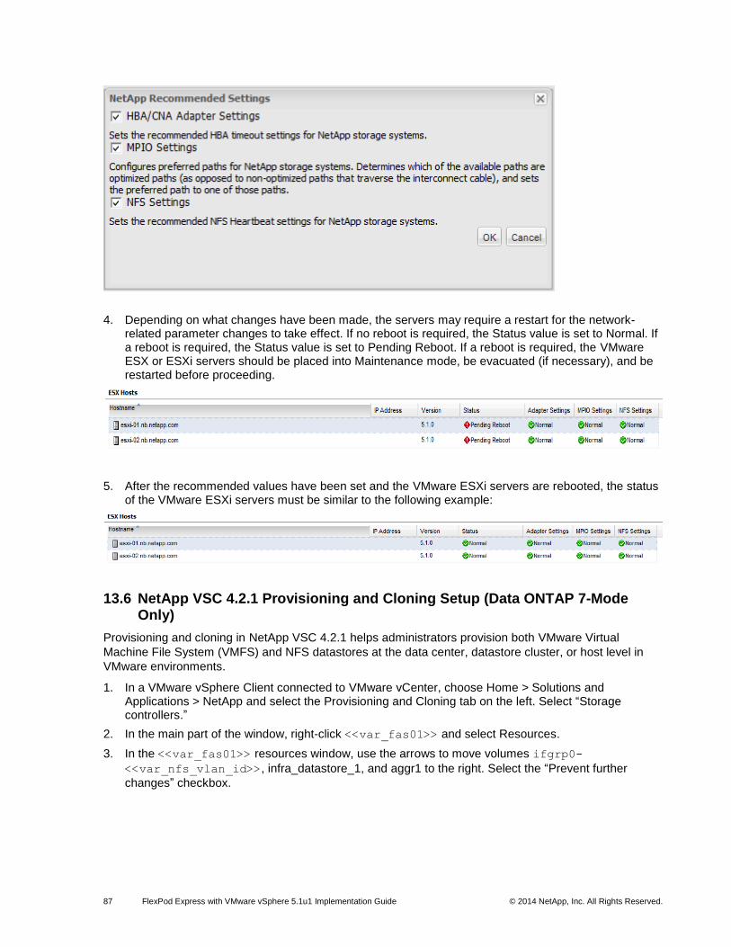
87 FlexPod Express with VMware vSphere 5.1u1 Implementation Guide © 2014 NetApp, Inc. All Rights Reserved.
4. Depending on what changes have been made, the servers may require a restart for the network-related parameter changes to take effect. If no reboot is required, the Status value is set to Normal. If a reboot is required, the Status value is set to Pending Reboot. If a reboot is required, the VMware ESX or ESXi servers should be placed into Maintenance mode, be evacuated (if necessary), and be restarted before proceeding.
5. After the recommended values have been set and the VMware ESXi servers are rebooted, the status of the VMware ESXi servers must be similar to the following example:
13.6 NetApp VSC 4.2.1 Provisioning and Cloning Setup (Data ONTAP 7-Mode Only)
Provisioning and cloning in NetApp VSC 4.2.1 helps administrators provision both VMware Virtual
Machine File System (VMFS) and NFS datastores at the data center, datastore cluster, or host level in
VMware environments.
1. In a VMware vSphere Client connected to VMware vCenter, choose Home > Solutions and Applications > NetApp and select the Provisioning and Cloning tab on the left. Select “Storage controllers.”
2. In the main part of the window, right-click <<var_fas01>> and select Resources.
3. In the <<var_fas01>> resources window, use the arrows to move volumes ifgrp0-
<<var_nfs_vlan_id>>, infra_datastore_1, and aggr1 to the right. Select the “Prevent further
changes” checkbox.

88 FlexPod Express with VMware vSphere 5.1u1 Implementation Guide © 2014 NetApp, Inc. All Rights Reserved.
4. Click Save.
5. In the main window, right-click <<var_fas02>> and select Resources.
6. In the <<var_fas02>> resources window, use the arrows to move ifgrp0-
<<var_nfs_vlan_id>> to the right. Select the “Prevent further changes” checkbox.

89 FlexPod Express with VMware vSphere 5.1u1 Implementation Guide © 2014 NetApp, Inc. All Rights Reserved.
7. Click Save.
13.7 NetApp VSC 4.2.1 Backup and Recovery
Prerequisites to use Backup and Recovery Capability
Before you begin using the NetApp VSC Backup and Recovery capability to schedule backups and
restore your datastores, virtual machines, and virtual disk files, you must make sure that the storage
systems that contain the datastores and virtual machines for which you are creating backups have valid
storage credentials in the Monitoring and Host Configuration section.
If you are planning to use the NetApp SnapMirror® update option, add all the destination storage systems
with valid storage credentials to the Monitoring and Host Configuration section.
Backup and Recovery Configuration
The following steps detail the procedure to configure a backup job for a datastore.
1. Click Backup and Recovery and then select Backup.
2. Click Add. The Backup wizard appears.
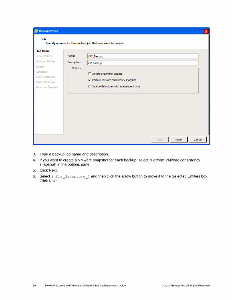
90 FlexPod Express with VMware vSphere 5.1u1 Implementation Guide © 2014 NetApp, Inc. All Rights Reserved.
3. Type a backup job name and description.
4. If you want to create a VMware snapshot for each backup, select “Perform VMware consistency snapshot” in the options pane.
5. Click Next.
6. Select infra_datastore_1 and then click the arrow button to move it to the Selected Entities box.
Click Next.

91 FlexPod Express with VMware vSphere 5.1u1 Implementation Guide © 2014 NetApp, Inc. All Rights Reserved.
7. Select one or more backup scripts if available and click Next.

92 FlexPod Express with VMware vSphere 5.1u1 Implementation Guide © 2014 NetApp, Inc. All Rights Reserved.
8. Select the hourly, daily, weekly, or monthly schedule that you want for this backup job and click Next.

93 FlexPod Express with VMware vSphere 5.1u1 Implementation Guide © 2014 NetApp, Inc. All Rights Reserved.
9. Use the default VMware vCenter credentials or type the user name and password for the VMware vCenter Server and click Next.
10. Specify backup retention details based on your requirements. Enter an e-mail address to receive e-mail alerts. You can add multiple e-mail addresses by using semicolons to separate e-mail addresses. Click Next.
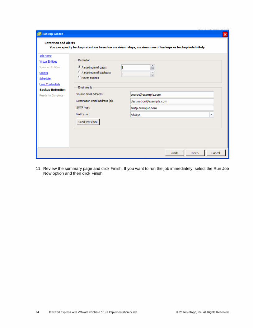
94 FlexPod Express with VMware vSphere 5.1u1 Implementation Guide © 2014 NetApp, Inc. All Rights Reserved.
11. Review the summary page and click Finish. If you want to run the job immediately, select the Run Job Now option and then click Finish.

95 FlexPod Express with VMware vSphere 5.1u1 Implementation Guide © 2014 NetApp, Inc. All Rights Reserved.
12. In the storage cluster interface, automatic snapshot copies of the volume can be disabled by typing the following command:
volume modify –volume infra_datastore_1 –snapshot-policy none
13. To delete any existing automatic snapshot copies that have been created on the volume, type the following command:
volume snapshot show –volume infra_datastore_1
volume snapshot delete –volume infra_datastore_1 <snapshot name>
14 Bill of Materials
This section details the hardware and software components used in validating both the small and medium
FlexPod Express configurations included in this document.
Small Configuration
Table 16) Small configuration components.
Part Number Product Description Quantity Required
Cisco Components
UCSC-C220-M3S UCS C220 M3 SFF w/o CPU, mem, HDD, PCIe, PSU, w/ rail kit
2
UCS-CPU-E52650B 2.60 GHz E5-2650 v2/95W 8C/20MB Cache/DDR3 1866MHz
4
UCS-MR-1X082RY-A 8GB DDR3-1600-MHz RDIMM/PC3- 32

96 FlexPod Express with VMware vSphere 5.1u1 Implementation Guide © 2014 NetApp, Inc. All Rights Reserved.
Part Number Product Description Quantity Required
12800/dual rank/1.35v
A03-D600GA2 600GB 6Gb SAS 10K RPM SFF HDD/hot plug/drive sled mounted
4
CAB-C13-C14-AC Power cord, C13 to C14 (recessed receptacle), 10A
4
UCSC-PSU-450W 450W power supply for C-series rack servers
4
UCSC-RAID-11-C220 Cisco UCS RAID SAS 2008M-8i Mezz Card for C220 (0/1/10/5/50)
2
N2XX-ABPCI03-M3 Broadcom 5709 Quad Port 1Gb w/TOE iSCSI for M3 Servers
2
UCS-SD-16G 16GB SD Card module for UCS Servers 4
N20-BBLKD UCS 2.5 inch HDD blanking panel 12
UCSC-HS-C220M3 Heat Sink for UCS C220 M3 Rack Server 4
UCSC-PCIF-01F Full height PCIe filler for C-Series 2
UCSC-PCIF-01H Half height PCIe filler for UCS 2
UCSC-RAIL1 Rail Kit for C220, C22, C24 rack servers 2
CON-SNT-C220M3SF SMARTNET 8X5XNBD UCS C220 M3 SFF w/o
2
NetApp Components
FAS2220-R6 1
FAS2220A-12X600-R6 FAS2220,HA,12x600GB,10k,Dual CNTLR
1
FAS2220A-HA-SW-R6 FAS2220A,HA CFO Software 2
SW-2220A-ONTAP8-P SW, Data ONTAP Essentials,2220A,-P 2
SW-CIFS-C SW,CIFS,-C 2
SW-FCP-C SW,FCP,-C 2
SW-ISCSI-C SW, iSCSI,-C 2
SW-NFS-C SW,NFS,-C 2
X5518A-R6 Rack Mount Kit,FAS2020/40,R6 1
X800-42U-R6 Cabinet Component Power Cable,R6 2
Use NetApp QuoteEdge to determine part number
SupportEdge Standard, Premium or equivalent service from an authorized support services partner
1
1
1SupportEdge Premium required for cooperative support.
Medium Configuration
Table 17) Medium configuration components.
Part Number Product Description Quantity Required
Cisco Components
UCSC-C220-M3S UCS C220 M3 SFF w/o CPU, mem, HDD, PCIe, PSU, w/ rail kit
4
UCS-CPU-E52650B 2.60 GHz E5-2650 v2/95W 8C/20MB 8
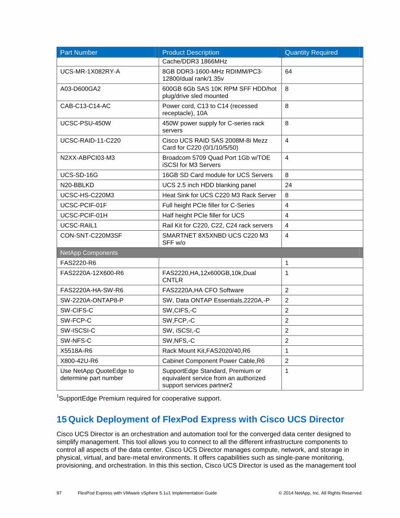
97 FlexPod Express with VMware vSphere 5.1u1 Implementation Guide © 2014 NetApp, Inc. All Rights Reserved.
Part Number Product Description Quantity Required
Cache/DDR3 1866MHz
UCS-MR-1X082RY-A 8GB DDR3-1600-MHz RDIMM/PC3-12800/dual rank/1.35v
64
A03-D600GA2 600GB 6Gb SAS 10K RPM SFF HDD/hot plug/drive sled mounted
8
CAB-C13-C14-AC Power cord, C13 to C14 (recessed receptacle), 10A
8
UCSC-PSU-450W 450W power supply for C-series rack servers
8
UCSC-RAID-11-C220 Cisco UCS RAID SAS 2008M-8i Mezz Card for C220 (0/1/10/5/50)
4
N2XX-ABPCI03-M3 Broadcom 5709 Quad Port 1Gb w/TOE iSCSI for M3 Servers
4
UCS-SD-16G 16GB SD Card module for UCS Servers 8
N20-BBLKD UCS 2.5 inch HDD blanking panel 24
UCSC-HS-C220M3 Heat Sink for UCS C220 M3 Rack Server 8
UCSC-PCIF-01F Full height PCIe filler for C-Series 4
UCSC-PCIF-01H Half height PCIe filler for UCS 4
UCSC-RAIL1 Rail Kit for C220, C22, C24 rack servers 4
CON-SNT-C220M3SF SMARTNET 8X5XNBD UCS C220 M3 SFF w/o
4
NetApp Components
FAS2220-R6 1
FAS2220A-12X600-R6 FAS2220,HA,12x600GB,10k,Dual CNTLR
1
FAS2220A-HA-SW-R6 FAS2220A,HA CFO Software 2
SW-2220A-ONTAP8-P SW, Data ONTAP Essentials,2220A,-P 2
SW-CIFS-C SW,CIFS,-C 2
SW-FCP-C SW,FCP,-C 2
SW-ISCSI-C SW, iSCSI,-C 2
SW-NFS-C SW,NFS,-C 2
X5518A-R6 Rack Mount Kit,FAS2020/40,R6 1
X800-42U-R6 Cabinet Component Power Cable,R6 2
Use NetApp QuoteEdge to determine part number
SupportEdge Standard, Premium or equivalent service from an authorized support services partner2
1
1SupportEdge Premium required for cooperative support.
15 Quick Deployment of FlexPod Express with Cisco UCS Director
Cisco UCS Director is an orchestration and automation tool for the converged data center designed to
simplify management. This tool allows you to connect to all the different infrastructure components to
control all aspects of the data center. Cisco UCS Director manages compute, network, and storage in
physical, virtual, and bare-metal environments. It offers capabilities such as single-pane monitoring,
provisioning, and orchestration. In this this section, Cisco UCS Director is used as the management tool

98 FlexPod Express with VMware vSphere 5.1u1 Implementation Guide © 2014 NetApp, Inc. All Rights Reserved.
for our FlexPod Express cloud. For instructions on how to set up the Cisco UCS Director software and to
quickly deploy a VM deployment self-service portal, refer to
http://www.cisco.com/c/en/us/solutions/collateral/data-center-virtualization/unified-computing/whitepaper-
c11-731143.html.
Refer to the Interoperability Matrix Tool (IMT) on the NetApp Support site to validate that the exact product and feature versions described in this document are supported for your specific environment. The NetApp IMT defines the product components and versions that can be used to construct configurations that are supported by NetApp. Specific results depend on each customer's installation in accordance with published specifications.
NetApp provides no representations or warranties regarding the accuracy, reliability, or serviceability of any information or recommendations provided in this publication, or with respect to any results that may be obtained by the use of the information or observance of any recommendations provided herein. The information in this document is distributed AS IS, and the use of this information or the implementation of any recommendations or techniques herein is a customer’s responsibility and depends on the customer’s ability to evaluate and integrate them into the customer’s operational environment. This document and the information contained herein may be used solely in connection with the NetApp products discussed in this document.
© 2014 NetApp, Inc. All rights reserved. No portions of this document may be reproduced without prior written consent of NetApp, Inc. Specifications are subject to change without notice. NetApp, the NetApp logo, Go further, faster, AutoSupport, Data ONTAP, FlexClone, FlexPod, FlexVol, SnapManager, SnapMirror, SnapRestore, and Snapshot are trademarks or registered trademarks of NetApp, Inc. in the United States and/or other countries. Cisco, Cisco Nexus, and Cisco UCS are registered trademarks and Cisco Unified Computing System is a trademark of Cisco Systems. Active Directory, Microsoft, SQL Server, Windows, and Windows Server are registered trademarks of Microsoft Corporation. ESX, vMotion, VMware, and VMware vSphere are registered trademarks and ESXi and vCenter are trademarks of VMware, Inc. Intel is a registered trademark of Intel Corporation. All other brands or products are trademarks or registered trademarks of their respective holders and should be treated as such. TR-4261-0314