Embed Size (px)
Citation preview
TECHNICAL PAPER
BOP Tethering and Motion
Measurements – Enabling Safe
Subsea Well Decommissioning
J. Lodhia
AOG March 2019


BOP Tethering and Motion Measurements – Enabling Safe Subsea Well Decommissioning
14th March 2019
J Lodhia
Learn more at www.2hoffshore.com
3 of 21
Contents
▪ Subsea well P&A challenges
▪ Benefits of BOP tether system
▪ Specification of BOP tether system
▪ In-field measurements to validate response
▪ Conclusions
Learn more at www.2hoffshore.com
4 of 21
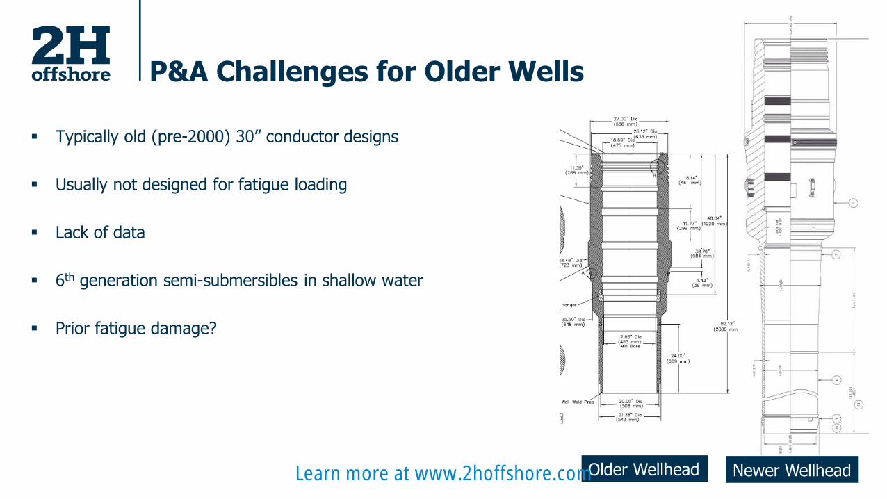
P&A Challenges for Older Wells
▪ Typically old (pre-2000) 30” conductor designs
▪ Usually not designed for fatigue loading
▪ Lack of data
▪ 6th generation semi-submersibles in shallow water
▪ Prior fatigue damage?
Older Wellhead Newer WellheadLearn more at www.2hoffshore.com
5 of 21
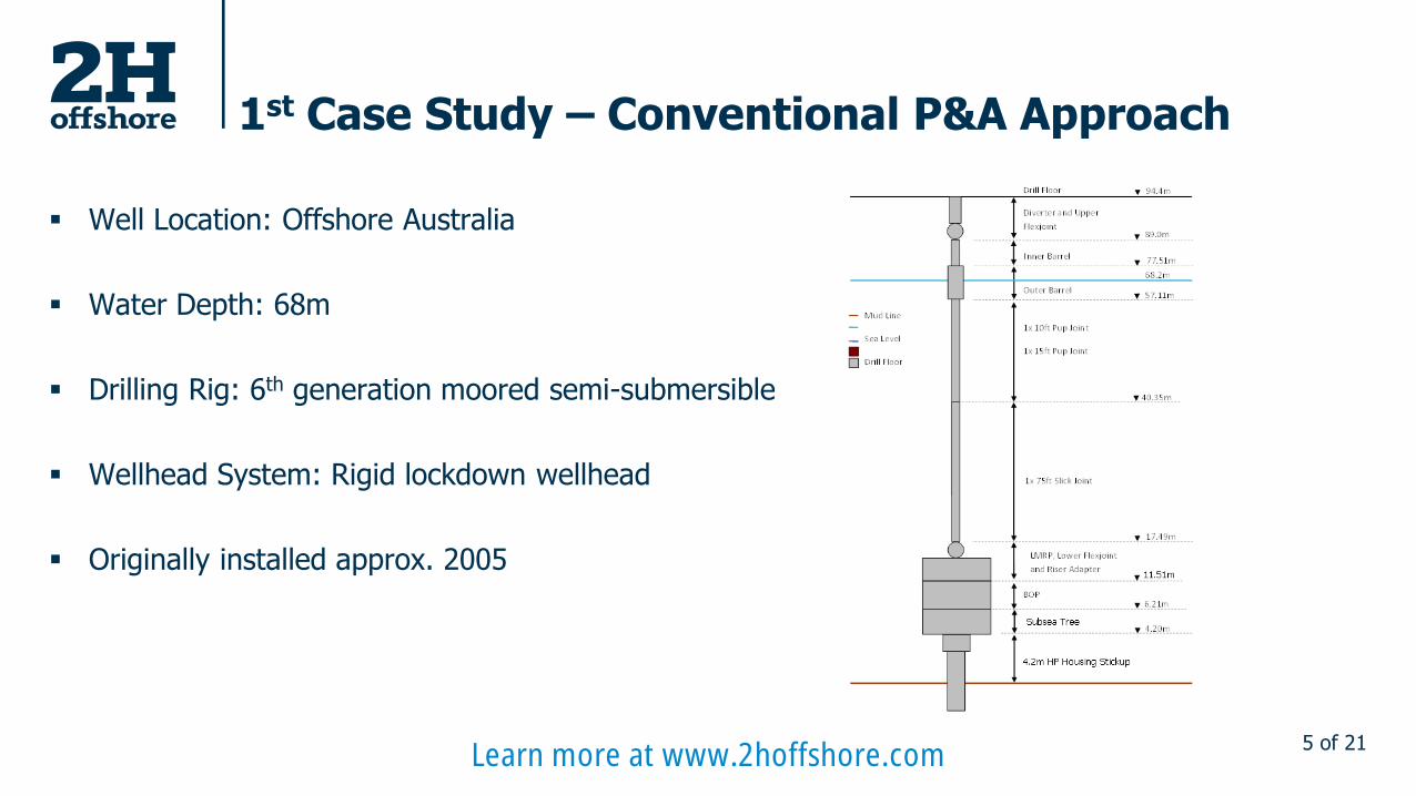
1st Case Study – Conventional P&A Approach
▪ Well Location: Offshore Australia
▪ Water Depth: 68m
▪ Drilling Rig: 6th generation moored semi-submersible
▪ Wellhead System: Rigid lockdown wellhead
▪ Originally installed approx. 2005
Learn more at www.2hoffshore.com

6 of 21
Wellhead & Conductor Stack-up
▪ 30” x 1.0” Conductor
▪ 20”x13-3/8” Surface Casing
▪ Conductor and surface casing cemented to mudline
▪ Combined wet weight of LMRP + BOP + Subsea Tree = 232.7Te
▪ 25 day duration = 250 days target life (0.68 years) FOS=10
LP Housing:0.97m
3.35m
Mud Line Mud
HP Housing: 1.72m
11.51m
2.48m 2.38m
0m
Cement
-8.09m
30x1.5” LP Hsg Extension Joint
6.21m
4.20m
BOP: 5.30m
Subsea Tree: 2.01m
17.49m
Riser Adapter, Lower Flex Joint and LMRP: 5.98m
30x1” XOver Joint 30x1” Intermediate Joint
1 x 30” x 1.50” Conductor Joint
-19.57m
-31.05m
-42.63m
20x 13-3/8” Surface Casing
10-3/4” x 9-5/8” Casing
13-3/8” Casing Shoe -565.1m
Surface Casing TOC 0m
-4.00m Base of HD90 Quick Stab Box
-5.90m Top 13-3/8” BTC Connector
9-5/8” Casing Shoe -1630.1m
-1596.3m 7” Tubing Packer
Learn more at www.2hoffshore.com
7 of 21
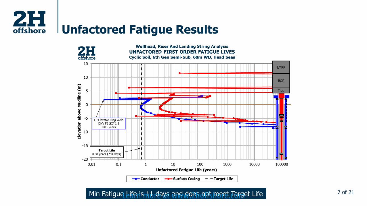
Unfactored Fatigue Results
Min Fatigue Life is 11 days and does not meet Target LifeLearn more at www.2hoffshore.com
8 of 21
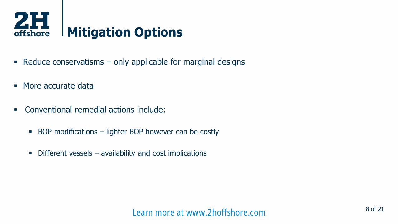
Mitigation Options
▪ Reduce conservatisms – only applicable for marginal designs
▪ More accurate data
▪ Conventional remedial actions include:
▪ BOP modifications – lighter BOP however can be costly
▪ Different vessels – availability and cost implications
Learn more at www.2hoffshore.com
9 of 21
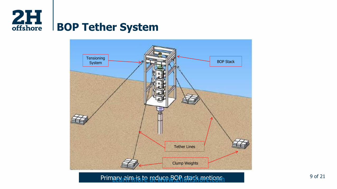
BOP Tether System
Clump Weights
BOP StackTensioning
System
Tether Lines
Primary aim is to reduce BOP stack motionsLearn more at www.2hoffshore.com
10 of 21
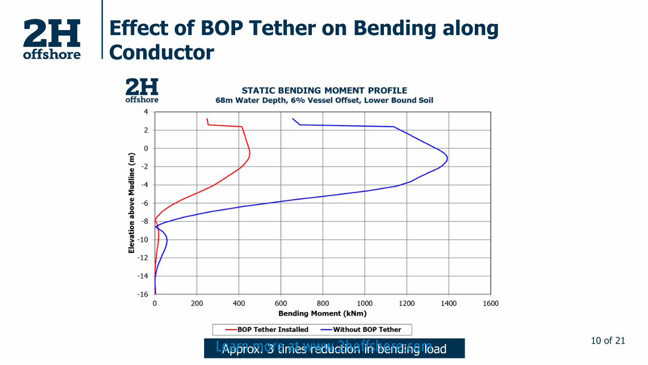
Effect of BOP Tether on Bending along Conductor
Approx. 3 times reduction in bending loadLearn more at www.2hoffshore.com
11 of 21
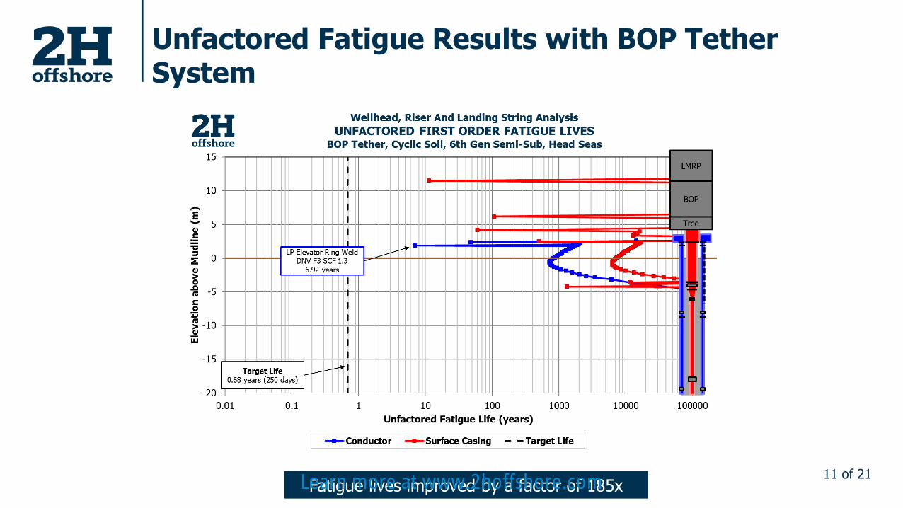
Unfactored Fatigue Results with BOP Tether System
Fatigue lives improved by a factor of 185xLearn more at www.2hoffshore.com

12 of 21
Specifying BOP Tether SystemKey Considerations
▪ Consider how any change in the design will affect the overall tether wire stiffness:
▪ Clump weight position
▪ Tether wire length
▪ Tether wire OD / Maximum Breaking Force
▪ How does tether wire pre-tension impact the efficiency of the system?
▪ Monitoring system can provide further assurance
▪ Bottom clump weight stability on seabed
▪ Axial loading resistance on conductor – Any additional axial load?
Learn more at www.2hoffshore.com
13 of 21
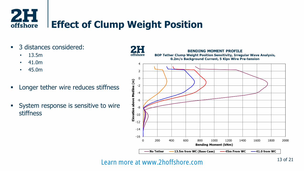
Effect of Clump Weight Position
▪ 3 distances considered:• 13.5m
• 41.0m
• 45.0m
▪ Longer tether wire reduces stiffness
▪ System response is sensitive to wire stiffness
Learn more at www.2hoffshore.com

14 of 21
Effect of Tether Pre-tension & Wire OD
▪ Tether wire OD reduced – Wire stiffness reduces by 87%
▪ 3 pre-tensions considered:• 5 kips
• 10 kips
• 15 kips
▪ Clump weight positions remains constant
▪ Wire pre-tension has little effect on system response
▪ System response is sensitive to wire stiffness
Learn more at www.2hoffshore.com

15 of 21
Final Fatigue Results with BOP Tether System
Learn more at www.2hoffshore.com
16 of 21
2nd Case Study – Monitoring BOP Stack Motions
▪ Well Location: Offshore Australia
▪ Subsea well utilised a BOP tether system
▪ Motion monitoring equipment installed subsea onto the BOP frame and subsea tree
▪ Monitoring equipment recorded the BOP stack and subsea tree movement and accelerations
▪ Data available pre- and post-BOP tether system installation for multiple deployments
Learn more at www.2hoffshore.com
17 of 21
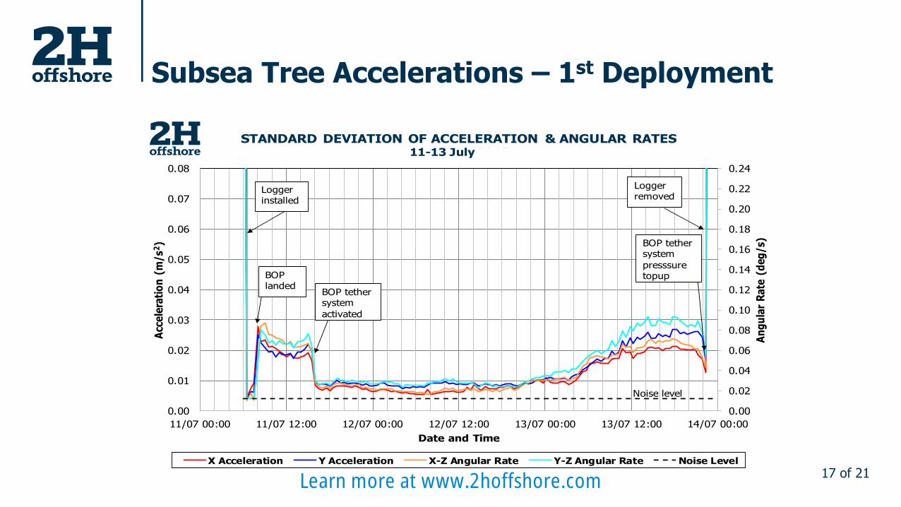
Subsea Tree Accelerations – 1st Deployment
0.00
0.02
0.04
0.06
0.08
0.10
0.12
0.14
0.16
0.18
0.20
0.22
0.24
0.00
0.01
0.02
0.03
0.04
0.05
0.06
0.07
0.08
11/07 00:00 11/07 12:00 12/07 00:00 12/07 12:00 13/07 00:00 13/07 12:00 14/07 00:00
An
gu
lar
Ra
te (
de
g/
s)
Acc
ele
rati
on
(m
/s2
)
Date and Time
Cooper Energy Sole-4 Tree Monitoring
STANDARD DEVIATION OF ACCELERATION & ANGULAR RATES11-13 July 2018
X Acceleration Y Acceleration X-Z Angular Rate Y-Z Angular Rate Noise Level
Logger installed
Loggerremoved
BOP landed
BOP tether system
activated
BOP tether system
presssuretopup
Noise level
Learn more at www.2hoffshore.com
18 of 21
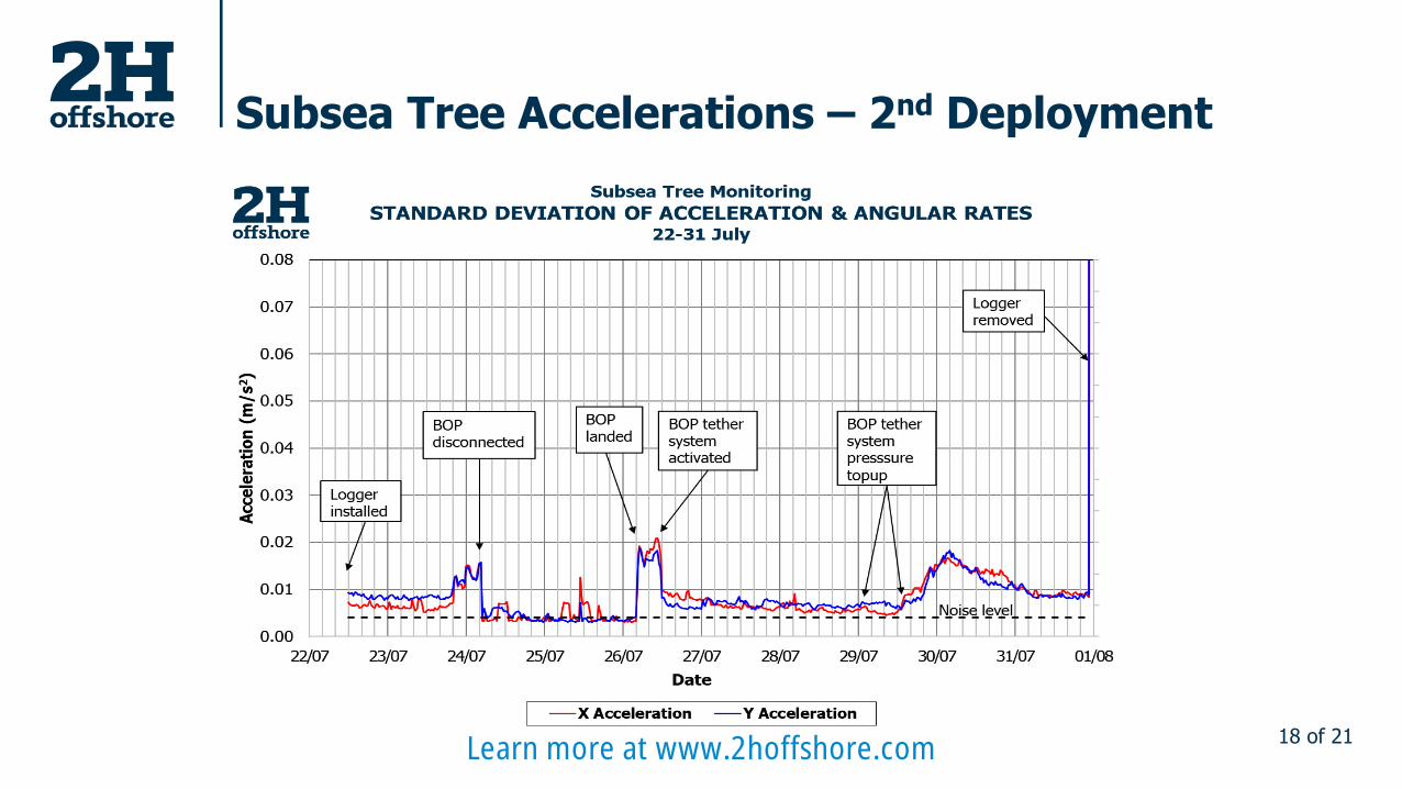
Subsea Tree Accelerations – 2nd Deployment
Learn more at www.2hoffshore.com
19 of 21
Observations From In-field Measurements
▪ Use of the BOP tether system provided 2.5x reduction in motions
▪ Consistent reduction in BOP stack motions observed over multiple deployments
▪ The observed reduction in motions directly leads to improved fatigue performance
Learn more at www.2hoffshore.com
20 of 21
Summary
▪ Use of 5/6th generation rig for subsea well P&A decommissioning may lead to fatigue complications
▪ Standard remedial actions may be insufficient or too costly
▪ BOP tether system offers a direct improvement on wellhead fatigue by reducing BOP stack motions
▪ Must consider wire stiffness when designing the BOP tether system
▪ In-field motion measurements confirm the effectiveness of a BOP tether system in reducing stack motions
Learn more at www.2hoffshore.com

Questions?
Learn more at www.2hoffshore.com