Embed Size (px)
Citation preview
ONLINE MARINE ENGINEERING
In Field Mooring Analysis Report FOR VESSEL BARGE AMT DISCOVERER AND WATERDEPTH 30M
Project
TEST MOORING PROJECT DEMO RUN WITH MIDLINE BOUY
Client NONE
Issue Date 08/02/2010
Report reference number: Demo-08-Feb-10-29087 Report Prepared by: Online Marine Engineering www.transportanalysis.com
Report template revision: R.2.0

In-Field Mooring Analysis Report TEST MOORING PROJECT DEMO RUN WITH MIDLINE BOUY
Page Date
: :
2 of 13 08/02/2010
ONLINE MARINE
ENGINEERING
TABLE OF CONTENTS 1.0� GENERAL ..................................................................................................................................... 4�
1.1� Introduction ................................................................................................................................ 4�
1.2� Scope ......................................................................................................................................... 4�
1.3� Design Criteria ........................................................................................................................... 4�
1.4� Cargo characteristics ................................................................................................................. 7�
1.5� Barge Characteristic .................................................................................................................. 7�
2.0� SUMMARY OF RESULTS AND CONCLUSIONS ........................................................................ 9�
2.1� Summary of Results .................................................................................................................. 9�
2.2� Conclusions ............................................................................................................................... 9�
3.0� COMPUTER MODEL .................................................................................................................. 10�
3.1� General .................................................................................................................................... 10�
3.2� Description of the barge model ................................................................................................ 10�
3.3� Description of the mooring Model ............................................................................................ 10�
4.0� MOORING ANALYSIS ................................................................................................................ 12�
4.1� Static loads .............................................................................................................................. 12�
4.2� First order motions ................................................................................................................... 12�
4.3� Single Line characteristics ....................................................................................................... 12�
4.4� Mooring line loads .................................................................................................................... 12�
Attachment 1: Computer Output

In-Field Mooring Analysis Report TEST MOORING PROJECT DEMO RUN WITH MIDLINE BOUY
Page Date
: :
3 of 13 08/02/2010
ONLINE MARINE
ENGINEERING
References 1. "General Guidelines for Marine Transportation”. Noble Denton International Limited, Rep No.
0030/NDI/JR Rev. 2, April 2005. 2. "Rules for planning and executing marine operations", DNV, 1999, incl. ADDENDUM 2000 3. "Design and Analysis of Stationkeeping Systems for Floating Structures", API, RP-2SK 3rd Edition,
October 2005, incl. ADDENDUM AUG.2009. 4. "Online Moses Reference Manual”, UltraMarine

In-Field Mooring Analysis Report TEST MOORING PROJECT DEMO RUN WITH MIDLINE BOUY
Page Date
: :
4 of 13 08/02/2010
ONLINE MARINE
ENGINEERING
1.0 GENERAL
1.1 Introduction This report presents a mooring analysis for the vessel Barge AMT Discoverer at the Test Mooring Project on request of None. The report presents the used input data, a description of the method and a report of the analysis. Here the user can write a section which will be included in the introduction of the report. - Please use plain text. - HTML codes can not be used This Demo run shows the ability of the model to analyse a mooring spread using midline bouys. The analysis include wind This report has been created by Online Marine Engineering. It is the responsibility of the client to perform a quality check on the input and output to assure that the results are correct before they will be used for an operation.
1.2 Scope The scope of this work is to determine the mooring capacity of the Barge AMT Discoverer at work for the Test Mooring Project project. The amt_Disc will be moored with 4 caternary mooring legs in waterdepths of 30m.
The following loads will be applied at intervals of 15 degrees heading around the vessel.
- Wind forces - Wave drift forces - First Order motions of Vessel
The analysis will be performed with two tidal current load cases of constant heading and strength. The following two environmental conditions will be analysed :
- Operational Condition - Survival Condition
The mooring has been analysed using a quasi static approach including dynamic motions of the vessel. The model used includes a full 3-D representation of the mooring and the vessel. The hydrodynamic forces and motions of the vessel have been calculated using 3-D Diffraction
1.3 Design Criteria The following project specific mooring design criteria will be used taking into account the risks associated to this type of work and possible consequence of a mooring failure. Line tension Factor of Safety The following line tension factor of safety have been found: Guideline Intact Condition Damaged Analysis DNV Guidelines, ref 2 1.5x1.3 = 1.95 1.3x1.0 = 1.30 Quasi-Static API Guideline, ref 3 2.0 1.43 Quasi-Static API Guideline, ref 3 1.67 1.25 Dynamic
Table 1.1 Line tension Factor of Safety For both guidelines the FoS relates to the condition of the mooring intact or damaged. Furthermore the API defines a lower FoS when a Dynamic analysis is used which in general gives a better prediction of the line tensions. Up to a waterdepth of 300 m it can be assumed that the Quasi-static approach including the dynamics of the vessel represents an accurate prediction of the line tensions.
1. Intact conditions Quasi-static analysis including vessel dynamics

In-Field Mooring Analysis Report TEST MOORING PROJECT DEMO RUN WITH MIDLINE BOUY
Page Date
: :
5 of 13 08/02/2010
ONLINE MARINE
ENGINEERING
The following factor of safety on the line Minimum Breaking Load (MBL) will be used: - Condition: Operational: FoS = 2 - Condition: Survival: FoS = 1.67
2. Damaged condition
Design for damaged conditions can be considered not Applicable, if the planned duration of the operation from the final point of no return and the end of the operation is less than 72 hrs. According to DNV “Rules for Planning and Execution of marine Operations”, [Ref.2] design for a one broken line condition is not required if: • The mooring period is less than 72 hours. • Sufficient tug capacity is available to repair the mooring
Anchor load The maximum allowable anchor load will be based on the Ultimate Holding Load (UHL) divided by a factor of safety. API recommends a factor of safety between 0.8 and 1.0 based on the level of analysis.
The following factor of safety on the anchor Ultimate Holding Limit (UHL) will be used: - Condition: Operational: FoS = 1 - Condition: Survival: FoS = 0.8
Uplift Angle Uplift could seriously reduce the capacity of the anchor and should normally be limited to 10 degree. Maximum uplift angle: 10 degree Static plus dynamics. The uplift angle will not be checked in this analysis. By inspection of the line catenaries it can be seen if the allowable Uplift on the anchor is exceeded for the set tension limits based on the line strength.
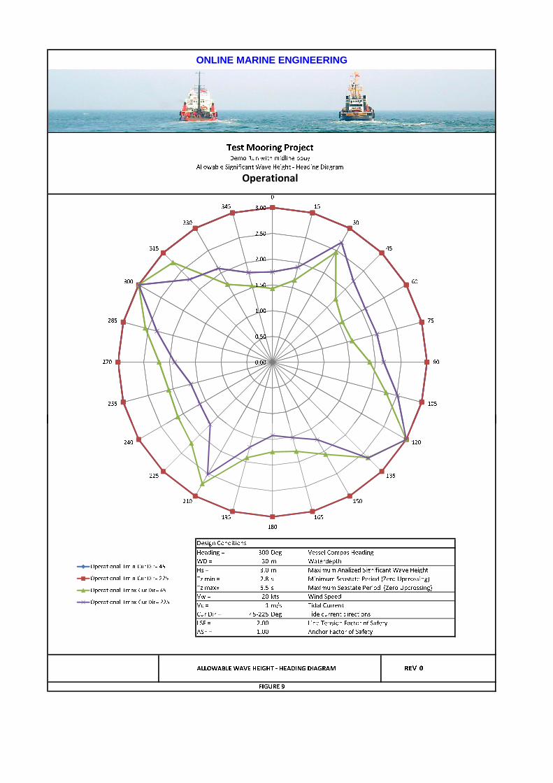
1.3.1 Environmental conditions The mooring will checked for two design conditions as defined in this section. For each heading the environment will be applied including the motions of the vessel and the allowable wave height at limiting mooring system utilisation will be reported. Wind will be assumed to work in the same direction as the wave at a constant force. The wind and wave environment will be combined with a tidal current with two fixed directions. The following describes the used environment in more detail: Environmental conditions Operational Survival Wind speed 20 kts mean (2 min) 40 kts mean (2 min) Maximum Analyzed Significant wave height (Hs) 3 m 4 m Minimum Peak Period (Tp) 4 s 7.21 s Minimum Zero Up-crossing Period (Tz) 2.84 s 5.12 s Minimum Gamma Factor (-) 1 1 Maximum Peak Period (Tp) 7.75 s 10.95 s Maximum Zero Up-crossing Period (Tz) 5.51 s 7.78 s Maximum Gamma Factor (-) 1 1 Current (Vc) 1 m/s 1 m/s Water depth 30 m 30 m
Table 1.1 Environmental conditions Seastate To represent the seastate a ISSC spectrum has been used with a cos2 spreading. For each design condition two seasate periods have been investigated and the allowable significant wave height will be reported for each heading. Design Wind Wind profile based on ABS. Design wind assumed to be defined at 10m above sealevel. Current Wind driven current has not been included.

In-Field Mooring Analysis Report TEST MOORING PROJECT DEMO RUN WITH MIDLINE BOUY
Page Date
: :
6 of 13 08/02/2010
ONLINE MARINE
ENGINEERING
Tidal current with a strength of 1 m/s coming from compass bearing 45 and 225 degree has been included. Waterdepth The mooring analysis have been done for the following waterdepth: Waterdepth = 30 m Heading The vessel will be moored at a heading of 300 degree.
1.4 Mooring Specification The following table presents the characteristics of the anchors that have been used for this study. ID Name UHC ULL Depth
- - Ton Deg m
01 First 300.0 10.00 30.00
02 Second 300.0 5.00 30.00
Table 1.2 Anchor characteristics Legend: UHC Ultimate Holding Capacity of the anchor ULL Allowable anchor Uplift angle Depth Waterdepth at anchor location The following table presents the characteristics of the mooring lines that has been used for this study. ID Name Anchor
Segments Clump Weight
Clump Offset
Size Dry Weight
Buoyancy Length MBL
- - No Name - Ton m mm kg/m kg/m m Ton
01 Line1 1 First 01 -50 10 50 12 5 250 250
02 0 0 50 13 5 150 250
02 Line2 2 Second 01 0 0 50 12 5 500 250
Table 1.2 Mooring lines characteristics Legend: Clump Weight Weight of Clump weight at start of line segment. Clump Offset Length of pennant wire connecting clump weight to mooring line Size Diameter of steel wire or chain Dry Weight Weight of anchor line per meter in air Buoyancy Buoyancy of anchor line per meter Length Length of segment (First Segment attached to winch) MBL Segment Minimum Breaking Load

In-Field Mooring Analysis Report TEST MOORING PROJECT DEMO RUN WITH MIDLINE BOUY
Page Date
: :
7 of 13 08/02/2010
ONLINE MARINE
ENGINEERING
The following table present the definition of the fair leaders and the mooring lines. Fairleaders Line Attached to fairleader
ID Name X Y Z Line ID
Line Name
Direction Distance Minimum Tension
- - m m m - - Deg m Ton
01 SBF -50.00 15.00 0.00 1 Line1 45.0 300.0 5.0
02 SBA 50.00 15.00 0.00 2 Line2 135.0 300.0 5.0
03 PSF -50.00 -15.00 0.00 2 Line2 -45.0 300.0 5.0
04 PSA 50.00 -15.00 0.00 1 Line1 -135.0 300.0 5.0
Table 1.3 Fair Leader and Mooring Spread Definition Legend: Name Name of fairleader. X Fairleader local vessel X coordinate Y Fairleader local vessel X coordinate Z Fairleader position above vessel deck Line ID ID of line attached to fair leader Line Name Name of line attached to fair leader Direction Line pay-out direction from fairleader in local vessel coordinate system Distance Line pay-out distance from fairleader in horizontal direction
1.5 Cargo characteristics The following table presents the characteristics of the additional cargo that has been modelled for this analysis. If no table is visible than no additional cargo has been modelled. No Name Weight LCG TCG VCG Roll
Radius Pitch
Radius Length Width Height
- Ton m m m m m m m m
1 0 3136.0 0.00 0.00 5.00 12.00 12.00 40.00 30.00 10.00
Total 3136.0 0.00 0.00 5.00
Table 1.4 Cargo characteristics Legend:
LCG = Longitudinal Centre of Gravity (From Midship to aft) TCG = Transverse Centre of Gravity (From Barge centreline to Starboard) VCG = Vertical Centre of Gravity (z) (From Barge deck upwards) Roll Radius = Roll Radius of Inertia Pitch Radius = Pitch Radius of Inertia Length = Length of Cargo Width = Width of cargo
1.6 Barge Characteristic The following vessel have been used: Name = Barge AMT Discoverer Model name = amt_Disc Length = 91.7 m Width = 30 m Depth = 7.6 m

In-Field Mooring Analysis Report TEST MOORING PROJECT DEMO RUN WITH MIDLINE BOUY
Page Date
: :
8 of 13 08/02/2010
ONLINE MARINE
ENGINEERING
Lightship = 2325.00 Ton with VCG at 4.40 m above keel
In-Field Mooring Analysis Report TEST MOORING PROJECT DEMO RUN WITH MIDLINE BOUY
Page Date
: :
9 of 13 08/02/2010
ONLINE MARINE
ENGINEERING
2.0 SUMMARY OF RESULTS AND CONCLUSIONS
2.1 Summary of Results The Mooring of the Barge AMT Discoverer for project TEST MOORING PROJECT has been checked for the environments and criteria as set in this report.
2.2 Conclusions The mooring analysis for the condition defined as OPERATIONAL revealed that all requirements as defined have been met. The mooring analysis for the condition defined as SURVIVAL revealed that all requirements as defined have been met.
In-Field Mooring Analysis Report TEST MOORING PROJECT DEMO RUN WITH MIDLINE BOUY
Page Date
: :
10 of 13 08/02/2010
ONLINE MARINE
ENGINEERING
3.0 COMPUTER MODEL
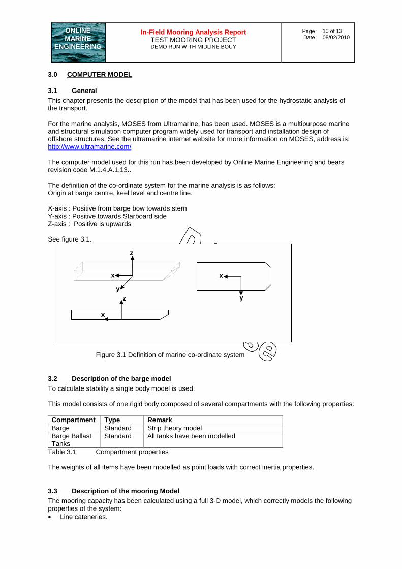
3.1 General This chapter presents the description of the model that has been used for the hydrostatic analysis of the transport. For the marine analysis, MOSES from Ultramarine, has been used. MOSES is a multipurpose marine and structural simulation computer program widely used for transport and installation design of offshore structures. See the ultramarine internet website for more information on MOSES, address is: http://www.ultramarine.com/ The computer model used for this run has been developed by Online Marine Engineering and bears revision code M.1.4.A.1.13.. The definition of the co-ordinate system for the marine analysis is as follows: Origin at barge centre, keel level and centre line. X-axis : Positive from barge bow towards stern Y-axis : Positive towards Starboard side Z-axis : Positive is upwards See figure 3.1.
Figure 3.1 Definition of marine co-ordinate system
3.2 Description of the barge model To calculate stability a single body model is used. This model consists of one rigid body composed of several compartments with the following properties: Compartment Type Remark Barge Standard Strip theory model Barge Ballast Tanks
Standard All tanks have been modelled
Table 3.1 Compartment properties The weights of all items have been modelled as point loads with correct inertia properties.
3.3 Description of the mooring Model The mooring capacity has been calculated using a full 3-D model, which correctly models the following properties of the system: • Line cateneries.
x
y
x
z
x
y
z
In-Field Mooring Analysis Report TEST MOORING PROJECT DEMO RUN WITH MIDLINE BOUY
Page Date
: :
11 of 13 08/02/2010
ONLINE MARINE
ENGINEERING
• Vessel submerged surface • Vessel Wind area • Hydrodynamic database computed using diffraction theory The following loads are calculated: Static Loads Wind load Current load Mean Wave drift loads Dynamic loads Wave induced motion around mean position. Wind and current loads have been calculated using Morrison’s equation and default drag coefficients as function of Reynolds. Dynamic loads have been calculated by superimposing the wave induced first order motions onto the static mean position.

In-Field Mooring Analysis Report TEST MOORING PROJECT DEMO RUN WITH MIDLINE BOUY
Page Date
: :
12 of 13 08/02/2010
ONLINE MARINE
ENGINEERING
4.0 MOORING ANALYSIS
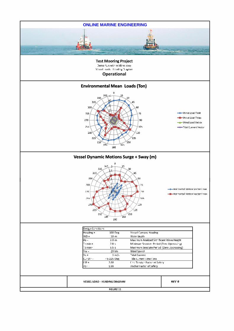
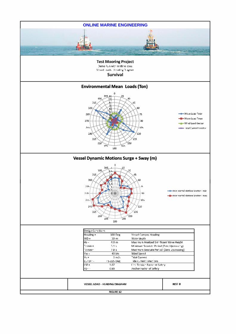
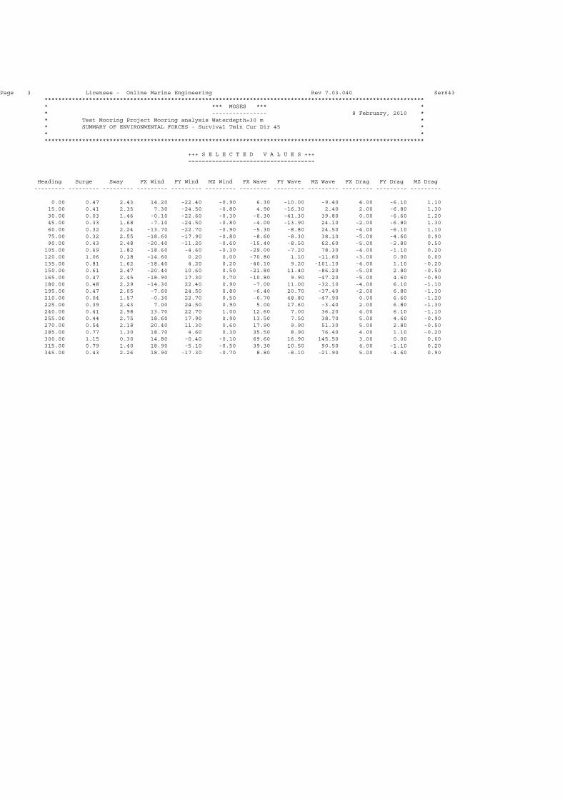
4.1 Static loads The static loads have been calculated for the applied directions. In attachment 1, figure 11 and 12 presents the wind and wave mean loads for the analysed conditions. Please note, the current drag has been given here for all headings, while the analysis only used the current forces for the specified headings. Numerical values of the loads can also be found in attachment 1 for all modelled environments.
4.2 First order motions The wave inducted first order motions in all directions are applied to the mooring lines to determine the dynamic loads. In attachment 1, figure 11 and 12 presents the combined surge and sway vector per heading for the analysed conditions. Figure 13 through 38 present the motion transfer functions based on the performed frequency domain motion analysis. The data base used for the motion analysis has been based on 3-D Diffraction. Numerical values of the motions can also be found in attachment 1 for all modelled environments. .
4.3 Single Line characteristics The single line characteristics can be found in attachment 1.
4.4 Mooring Operational limit Figure 9 and 10 in attachment 1 presents the mooring operational wave height limit based on the set criteria for all analysed headings.

In-Field Mooring Analysis Report TEST MOORING PROJECT DEMO RUN WITH MIDLINE BOUY
Page Date
: :
13 of 13 08/02/2010
ONLINE MARINE
ENGINEERING
ATTACHMENT 1: COMPUTER OUTPUT

Page 1 Licensee - Online Marine Engineering Rev 7.03.040 Ser643 *************************************************************************************************************** * *** MOSES *** * * ---------------- 8 February, 2010 * * User: Demo NO.: 1 - Test Mooring Project * * Barge Compartments * * * ***************************************************************************************************************
+++ C O M P A R T M E N T P R O P E R T I E S +++ ===================================================
Results Are Reported In Body System
Process is DEFAULT: Units Are Degrees, Meters, and M-Tons Unless Specified
Fill Specific /--- Ballast ---/ /------ % Full --------/ Sounding Name Type Gravity Maximum Current Max. Min. Curr. --------
CP2 CORRECT 1.0247 939.3 0.0 0.00 0.00 0.00 0.000 CP3 CORRECT 1.0247 939.3 0.0 0.00 0.00 0.00 0.000 CP4 CORRECT 1.0247 939.3 0.0 0.00 0.00 0.00 0.000 CP5 CORRECT 1.0247 939.3 0.0 0.00 0.00 0.00 0.000 CS2 CORRECT 1.0247 939.3 0.0 0.00 0.00 0.00 0.000 CS3 CORRECT 1.0247 939.3 0.0 0.00 0.00 0.00 0.000 CS4 CORRECT 1.0247 939.3 0.0 0.00 0.00 0.00 0.000 CS5 CORRECT 1.0247 939.3 0.0 0.00 0.00 0.00 0.000 P1 CORRECT 1.0247 830.5 0.0 0.00 0.00 0.00 0.000 S1 CORRECT 1.0247 830.5 0.0 0.00 0.00 0.00 0.000 WP2 CORRECT 1.0247 939.3 0.0 0.00 0.00 0.00 0.000 WP3 CORRECT 1.0247 939.3 0.0 0.00 0.00 0.00 0.000 WP4 CORRECT 1.0247 939.3 0.0 0.00 0.00 0.00 0.000 WP5 CORRECT 1.0247 939.3 0.0 0.00 0.00 0.00 0.000 WP6 CORRECT 1.0247 828.8 0.0 0.00 0.00 0.00 0.000 WS2 CORRECT 1.0247 939.3 0.0 0.00 0.00 0.00 0.000 WS3 CORRECT 1.0247 939.3 0.0 0.00 0.00 0.00 0.000 WS4 CORRECT 1.0247 939.3 0.0 0.00 0.00 0.00 0.000 WS5 CORRECT 1.0247 939.3 0.0 0.00 0.00 0.00 0.000 WS6 CORRECT 1.0247 828.8 0.0 0.00 0.00 0.00 0.000

Page 2 Licensee - Online Marine Engineering Rev 7.03.040 Ser643 *************************************************************************************************************** * *** MOSES *** * * ---------------- 8 February, 2010 * * User: Demo NO.: 1 - Test Mooring Project * * BALLAST PLAN VESSEL amt_Disc L= 91.70m B= 30m D= 7.60m * * * ***************************************************************************************************************
+++ B U O Y A N C Y A N D W E I G H T F O R M O D E L +++ =================================================================
Process is DEFAULT: Units Are Degrees, Meters, and M-Tons Unless Specified
Results Are Reported In Body System
Draft = 2.28 Roll Angle = 0.00 Pitch Angle = 0.00
Wet Radii Of Gyration About CG
K-X = 11.82 K-Y = 20.36 K-Z = 19.96
GMT = 26.35 GML = 251.32
/-- Center of Gravity ---/ Sounding % Full Name Weight ---X--- ---Y--- ---Z--- -------- --------
---------------- Part AMT_DISC ------------ --- Contents --- CP2 21.78 -27.68 -3.81 0.09 0.18 2.32 CP3 11.69 -11.58 -3.81 0.05 0.09 1.24 CP4 1.60 4.52 -3.80 0.01 0.01 0.17 CS2 21.78 -27.68 3.81 0.09 0.18 2.32 CS3 11.69 -11.58 3.81 0.05 0.09 1.24 CS4 1.60 4.52 3.80 0.01 0.01 0.17 P1 27.42 -36.68 -7.62 0.68 1.10 3.30 S1 27.42 -36.68 7.62 0.68 1.10 3.30 WP2 21.78 -27.68 -11.43 0.09 0.18 2.32 WP3 11.69 -11.58 -11.43 0.05 0.09 1.24 WP4 1.60 4.52 -11.42 0.01 0.01 0.17 WS2 21.78 -27.68 11.43 0.09 0.18 2.32 WS3 11.69 -11.58 11.43 0.05 0.09 1.24 WS4 1.60 4.52 11.42 0.01 0.01 0.17 ---------------- Part CARGO1 ------------ LOAD_GRO 3136.00 0.12 0.00 12.60 ---------------- Part LIGHTSHI ------------ LOAD_GRO 2325.00 1.51 0.00 4.40 ---------------- Part MODEL ------------ ======== ======== ======= ======= ======= Total 5656.11 -0.19 0.00 8.80 Buoyancy 5656.11 -0.19 0.00 1.16

Page 3 Licensee - Online Marine Engineering Rev 7.03.040 Ser643 *************************************************************************************************************** * *** MOSES *** * * ---------------- 8 February, 2010 * * User: Demo NO.: 1 - Test Mooring Project * * BALLAST PLAN VESSEL amt_Disc L= 91.70m B= 30m D= 7.60m * * * ***************************************************************************************************************
+++ C O M P A R T M E N T P R O P E R T I E S +++ ===================================================
Results Are Reported In Body System
Process is DEFAULT: Units Are Degrees, Meters, and M-Tons Unless Specified
Fill Specific /--- Ballast ---/ /------ % Full --------/ Sounding Name Type Gravity Maximum Current Max. Min. Curr. --------
CP2 CORRECT 1.0247 939.3 21.8 2.32 0.00 2.32 0.177 CP3 CORRECT 1.0247 939.3 11.7 1.24 0.00 1.24 0.095 CP4 CORRECT 1.0247 939.3 1.6 0.17 0.00 0.17 0.013 CP5 CORRECT 1.0247 939.3 0.0 0.00 0.00 0.00 0.000 CS2 CORRECT 1.0247 939.3 21.8 2.32 0.00 2.32 0.177 CS3 CORRECT 1.0247 939.3 11.7 1.24 0.00 1.24 0.095 CS4 CORRECT 1.0247 939.3 1.6 0.17 0.00 0.17 0.013 CS5 CORRECT 1.0247 939.3 0.0 0.00 0.00 0.00 0.000 P1 CORRECT 1.0247 830.5 27.4 3.30 0.00 3.30 1.100 S1 CORRECT 1.0247 830.5 27.4 3.30 0.00 3.30 1.100 WP2 CORRECT 1.0247 939.3 21.8 2.32 0.00 2.32 0.177 WP3 CORRECT 1.0247 939.3 11.7 1.24 0.00 1.24 0.095 WP4 CORRECT 1.0247 939.3 1.6 0.17 0.00 0.17 0.013 WP5 CORRECT 1.0247 939.3 0.0 0.00 0.00 0.00 0.000 WP6 CORRECT 1.0247 828.8 0.0 0.00 0.00 0.00 0.000 WS2 CORRECT 1.0247 939.3 21.8 2.32 0.00 2.32 0.177 WS3 CORRECT 1.0247 939.3 11.7 1.24 0.00 1.24 0.095 WS4 CORRECT 1.0247 939.3 1.6 0.17 0.00 0.17 0.013 WS5 CORRECT 1.0247 939.3 0.0 0.00 0.00 0.00 0.000 WS6 CORRECT 1.0247 828.8 0.0 0.00 0.00 0.00 0.000
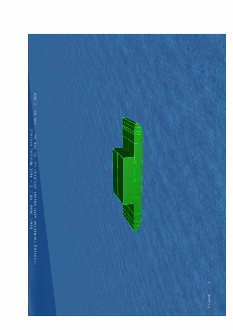

FIGURE 2
User: Demo NO.: 1 - Test Mooring Project
Floating Condition with Vessel amt_Disc L= 91.70m B= 30m D= 7.60m

FIGURE 3
User: Demo NO.: 1 - Test Mooring Project
Floating Condition with Vessel amt_Disc L= 91.70m B= 30m D= 7.60m

FIGURE 4
User: Demo NO.: 1 - Test Mooring Project
Floating Condition with Vessel amt_Disc L= 91.70m B= 30m D= 7.60m
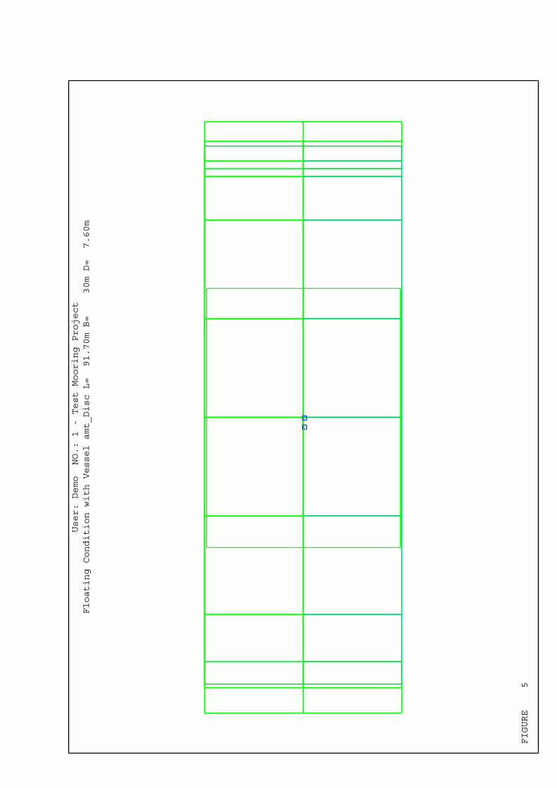
FIGURE 5
User: Demo NO.: 1 - Test Mooring Project
Floating Condition with Vessel amt_Disc L= 91.70m B= 30m D= 7.60m

FIGURE 6
User: Demo NO.: 1 - Test Mooring Project
BALLAST TANKS
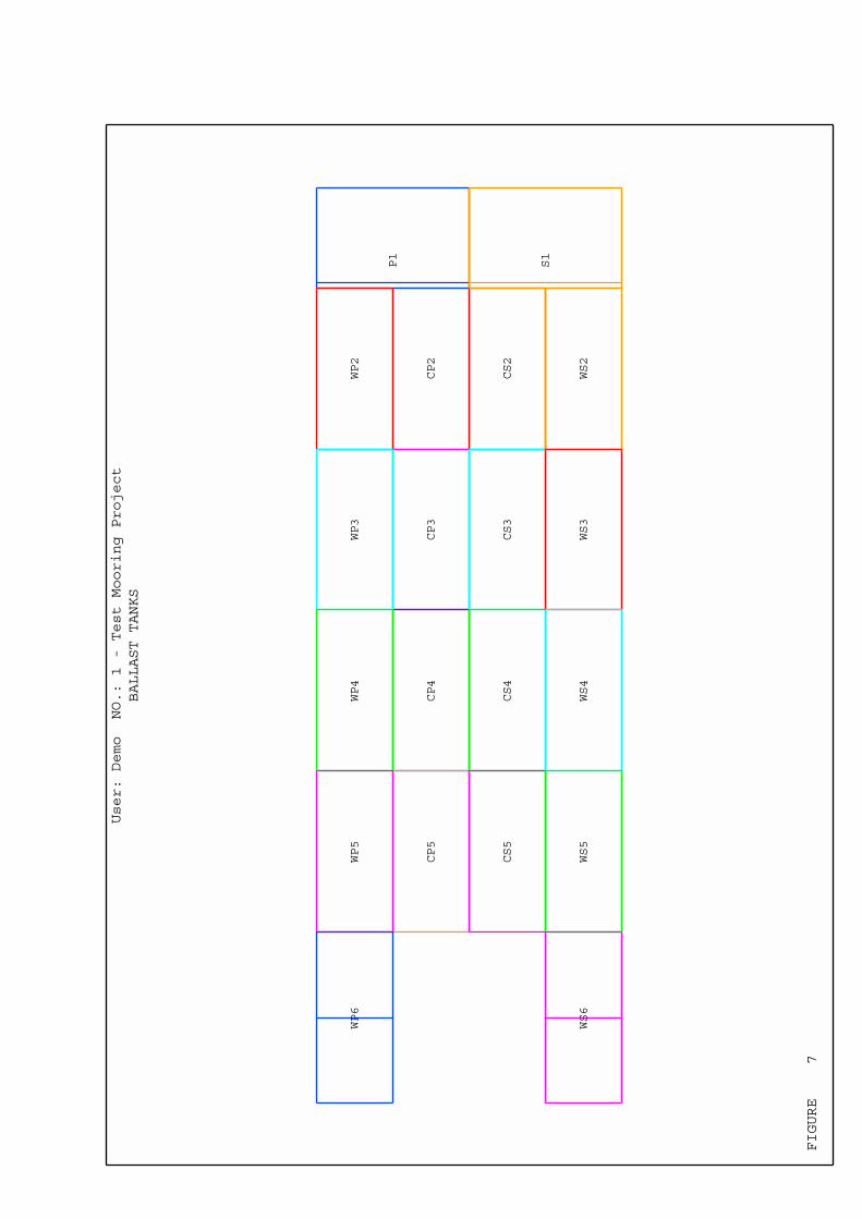
FIGURE 7
CP2
CP3
CP4
CP5
CS2
CS3
CS4
CS5
P1
S1
WP2
WP3
WP4
WP5
WP6
WS2
WS3
WS4
WS5
WS6
User: Demo NO.: 1 - Test Mooring Project
BALLAST TANKS
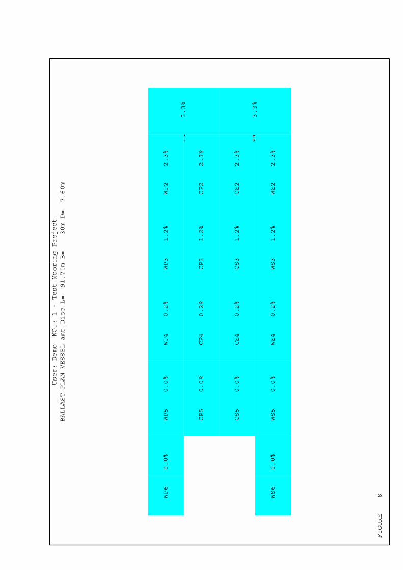
FIGURE 8
CP2 2.3%
CP3 1.2%
CP4 0.2%
CP5 0.0%
CS2 2.3%
CS3 1.2%
CS4 0.2%
CS5 0.0%
P1 3.3%
S1 3.3%
WP2 2.3%
WP3 1.2%
WP4 0.2%
WP5 0.0%
WP6 0.0%
WS2 2.3%
WS3 1.2%
WS4 0.2%
WS5 0.0%
WS6 0.0%
User: Demo NO.: 1 - Test Mooring Project
BALLAST PLAN VESSEL amt_Disc L= 91.70m B= 30m D= 7.60m
ONLINE MARINE ENGINEERING
������������ �������������������������������
�������������� ��������������������������
���������
����
����
����
����
����
����
����
�
��
��
��
��
�
�
������
��
���
���
���
���
���
��������������
�������� � ��� !���������"���������
���� � � �������"���
���� �# � $�%��������&����� ���������������
'&����� (#) � $�������������*�����+,����-"�������.
'&���%� /#/ � $�%������������*������+,����-"�������.
!��� ( 0�� ����"����
!��� 1 �2� '�����������
�������� 3/�((/ ��� '�������������������
45�� (# 4���'������5������� �� ���
�5�� 1# �������5������� �� ���
������������������� ������������� ��� �
�������
����
����
����
����
����
����
����
�
��
��
��
��
�
�
���
���
���
���
���
���
��
���
���
���
���
��
���
���
���
���
���
� ��������������������������
� ���������������������������
� ��������������������������
� ���������������������������

ONLINE MARINE ENGINEERING
������������ �������������������������������
�������������� ��������������������������
��� � �
����
����
����
����
����
����
����
����
����
�
��
��
��
��
�
�
������
��
���
���
���
���
���
��������������
�������� � ��� !���������"���������
���� � � �������"���
���� 3# � $�%��������&����� ���������������
'&����� /#1 � $�������������*�����+,����-"�������.
'&���%� 6#) � $�%������������*������+,����-"�������.
!��� 3 0�� ����"����
!��� 1 �2� '�����������
�������� 3/�((/ ��� '�������������������
45�� 1#76 4���'������5������� �� ���
�5�� #) �������5������� �� ���
������������������� ������������� ��� �
��������
����
����
����
����
����
����
����
����
����
�
��
��
��
��
�
�
���
���
���
���
���
���
��
���
���
���
���
��
���
���
���
���
���
��� � �������������������
��� � ��������������������
��� � �������������������
��� � ��������������������
ONLINE MARINE ENGINEERING
�������������� ��������������������������
!������4��������������������
���������
���
�
���
�
���
��
��
�����
���
������
������������� ����������������������
�
��
��
��
��
��
���
��
��
��
�
�
���
���
���
������
�����
���
���
���
���
��
���
���
���
������
������������ ���������������
!� ��"��#�����
!� ��"��#�����
!��#�"��#�$�%���
��#�����������$�%���
��������������
�������� � ��� !���������"���������
���� � � �������"���
���� �# � $�%��������&����� ���������������
'&����� (#) � $�������������*�����+,����-"�������.
'&���%� /#/ � $�%������������*������+,����-"�������.
!��� ( 0�� ����"����
!��� 1 �2� '�����������
�������� 3/�((/ ��� '�������������������
45�� (# 4���'������5������� �� ���
�5�� 1# �������5������� �� ���
������������ ������������� ��� �
��������
�
���
�
���
�
���
�
���
��
��
��
�
�
���
���
���
������
�����
���
���
���
���
��
���
���
���
������
������������� ����������������������
&���'������(������$�%��������
&���'������(������$�%��������
�
��
��
��
��
��
���
��
��
��
�
�
���
���
���
������
�����
���
���
���
���
��
���
���
���
������
������������ ���������������
!� ��"��#�����
!� ��"��#�����
!��#�"��#�$�%���
��#�����������$�%���
ONLINE MARINE ENGINEERING
�������������� ��������������������������
!������4��������������������
��� � �
�
��
��
��
��
��
��
�
��
���
��
��
��
�
�
���
���
���
������
�����
���
���
���
���
��
���
���
���
������
������������ ���������������
!� ��"��#�����
!� ��"��#�����
!��#�"��#�$�%���
��#�����������$�%���
� �
�
���
�
���
�
���
��
��
�����
���
������
������������� ����������������������
��������������
�������� � ��� !���������"���������
���� � � �������"���
���� 3# � $�%��������&����� ���������������
'&����� /#1 � $�������������*�����+,����-"�������.
'&���%� 6#) � $�%������������*������+,����-"�������.
!��� 3 0�� ����"����
!��� 1 �2� '�����������
�������� 3/�((/ ��� '�������������������
45�� 1#76 4���'������5������� �� ���
�5�� #) �������5������� �� ���
������������ ������������� ��� �
��������
�
��
��
��
��
��
��
�
��
���
��
��
��
�
�
���
���
���
������
�����
���
���
���
���
��
���
���
���
������
������������ ���������������
!� ��"��#�����
!� ��"��#�����
!��#�"��#�$�%���
��#�����������$�%���
�
���
�
���
�
���
�
���
�
���
��
��
��
�
�
���
���
���
������
�����
���
���
���
���
��
���
���
���
������
������������� ����������������������
&���'������(������$�%��������
&���'������(������$�%��������

Page 1 Licensee - Online Marine Engineering Rev 7.03.040 Ser643 *************************************************************************************************************** * *** MOSES *** * * ---------------- 8 February, 2010 * * Test Mooring Project * * Mooring Model * * * ***************************************************************************************************************
+++ B U O Y A N C Y A N D W E I G H T F O R M O D E L +++ =================================================================
Process is DEFAULT: Units Are Degrees, Meters, and M-Tons Unless Specified
Results Are Reported In Body System
Draft = 2.28 Roll Angle = 0.00 Pitch Angle = 0.00
Wet Radii Of Gyration About CG
K-X = 11.82 K-Y = 20.36 K-Z = 19.96
GMT = 26.35 GML = 251.32
/-- Center of Gravity ---/ Sounding % Full Name Weight ---X--- ---Y--- ---Z--- -------- --------
---------------- Part AMT_DISC ------------ --- Contents --- CP2 21.78 -27.68 -3.81 0.09 0.18 2.32 CP3 11.69 -11.58 -3.81 0.05 0.09 1.24 CP4 1.60 4.52 -3.80 0.01 0.01 0.17 CS2 21.78 -27.68 3.81 0.09 0.18 2.32 CS3 11.69 -11.58 3.81 0.05 0.09 1.24 CS4 1.60 4.52 3.80 0.01 0.01 0.17 P1 27.42 -36.68 -7.62 0.68 1.10 3.30 S1 27.42 -36.68 7.62 0.68 1.10 3.30 WP2 21.78 -27.68 -11.43 0.09 0.18 2.32 WP3 11.69 -11.58 -11.43 0.05 0.09 1.24 WP4 1.60 4.52 -11.42 0.01 0.01 0.17 WS2 21.78 -27.68 11.43 0.09 0.18 2.32 WS3 11.69 -11.58 11.43 0.05 0.09 1.24 WS4 1.60 4.52 11.42 0.01 0.01 0.17 ---------------- Part CARGO1 ------------ LOAD_GRO 3136.00 0.12 0.00 12.60 ---------------- Part LIGHTSHI ------------ LOAD_GRO 2325.00 1.51 0.00 4.40 ---------------- Part MODEL ------------ ======== ======== ======= ======= ======= Total 5656.11 -0.19 0.00 8.80 Buoyancy 5656.11 -0.19 0.00 1.16

Page 2 Licensee - Online Marine Engineering Rev 7.03.040 Ser643 *************************************************************************************************************** * *** MOSES *** * * ---------------- 8 February, 2010 * * Test Mooring Project * * Mooring pattern for Waterdepth 30 m * * * ***************************************************************************************************************
+++ C U R R E N T S Y S T E M C O N F I G U R A T I O N +++ ===============================================================
Process is DEFAULT: Units Are Degrees, Meters, and M-Tons Unless Specified
Location and Net Force at Body Origin
Body X Y Z RX RY RZ -------- --------- --------- --------- --------- --------- ---------
MODEL Location 0.00 0.00 -2.28 0.00 0.00 -210.00 N Force 0.00 0.00 -4.07 0 0 -6
Page 3 Licensee - Online Marine Engineering Rev 7.03.040 Ser643 *************************************************************************************************************** * *** MOSES *** * * ---------------- 8 February, 2010 * * Test Mooring Project * * Mooring pattern for Waterdepth 30 m * * * ***************************************************************************************************************
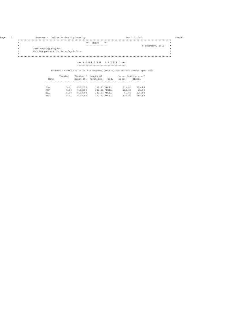
+++ M O O R I N G S P R E A D +++ ===================================
Process is DEFAULT: Units Are Degrees, Meters, and M-Tons Unless Specified
Tension Tension / Length of /----- Heading ----/ Name Break St. First Seg. Body Local Global -------- ---------- ---------- ---------- -------- --------- ----------
PSA 5.01 0.02050 152.73 MODEL 315.00 105.00 PSF 5.00 0.02000 303.11 MODEL 225.00 15.00 SBA 5.00 0.02000 303.11 MODEL 45.00 195.00 SBF 5.01 0.02050 152.73 MODEL 135.00 285.00

Page 4 Licensee - Online Marine Engineering Rev 7.03.040 Ser643 *************************************************************************************************************** * *** MOSES *** * * ---------------- 8 February, 2010 * * Test Mooring Project * * Mooring pattern for Waterdepth 30 m * * * ***************************************************************************************************************
+++ M O O R I N G L I N E S +++ =================================
Process is DEFAULT: Units Are Degrees, Meters, and M-Tons Unless Specified
Horiz. Length of Line on /----- Top ------/ /---- Anchor -----/ Name Distance First Seg Bottom Tension Ratio Hori Pull Vert Pull -------- --------- --------- --------- --------- --------- --------- ---------
PSA 300.00 152.73 0.00 5.01 0.0205 4.96 0.39 PSF 300.00 303.11 39.40 5.00 0.0200 4.82 0.00 SBA 300.00 303.11 39.40 5.00 0.0200 4.82 0.00 SBF 300.00 152.73 0.00 5.01 0.0205 4.96 0.39
Page 5 Licensee - Online Marine Engineering Rev 7.03.040 Ser643 *************************************************************************************************************** * *** MOSES *** * * ---------------- 8 February, 2010 * * Test Mooring Project * * Mooring pattern for Waterdepth 30 m * * * ***************************************************************************************************************
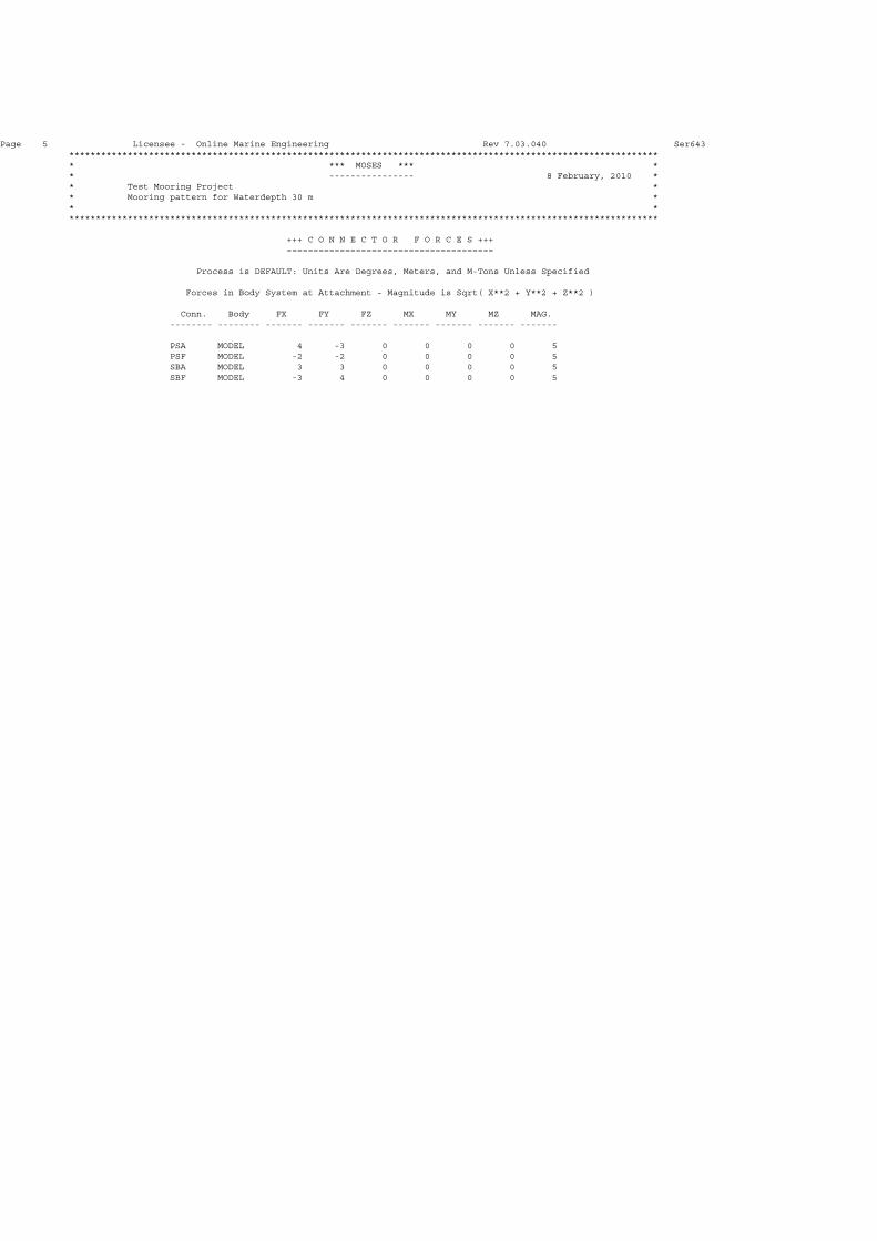
+++ C O N N E C T O R F O R C E S +++ =======================================
Process is DEFAULT: Units Are Degrees, Meters, and M-Tons Unless Specified
Forces in Body System at Attachment - Magnitude is Sqrt( X**2 + Y**2 + Z**2 )
Conn. Body FX FY FZ MX MY MZ MAG. -------- -------- ------- ------- ------- ------- ------- ------- -------
PSA MODEL 4 -3 0 0 0 0 5 PSF MODEL -2 -2 0 0 0 0 5 SBA MODEL 3 3 0 0 0 0 5 SBF MODEL -3 4 0 0 0 0 5

Page 6 Licensee - Online Marine Engineering Rev 7.03.040 Ser643 *************************************************************************************************************** * *** MOSES *** * * ---------------- 8 February, 2010 * * Test Mooring Project * * Mooring pattern for Waterdepth 30 m * * * ***************************************************************************************************************
+++ C O N N E C T O R G E O M E T R Y +++ ===========================================
Results in The First Body System
Process is DEFAULT: Units Are Degrees, Meters, and M-Tons Unless Specified
Length of /------------ Connection -------------/ Name Class Status First Seg. Body X Y Z -------- -------- -------- ---------- -------- --------- ---------- ---------
PSA ~LINE1 Active 152.73 MODEL 50.12 -15.00 7.60 GROUND -113.55 327.83 -30.00 PSF ~LINE2 Active 303.11 MODEL -49.88 -15.00 7.60 GROUND 340.48 65.70 -30.00 SBA ~LINE2 Active 303.11 MODEL 50.12 15.00 7.60 GROUND -340.68 -65.58 -30.00 SBF ~LINE1 Active 152.73 MODEL -49.88 15.00 7.60 GROUND 113.34 -327.71 -30.00

Page 7 Licensee - Online Marine Engineering Rev 7.03.040 Ser643 *************************************************************************************************************** * *** MOSES *** * * ---------------- 8 February, 2010 * * Test Mooring Project * * Dynamic run with HS= 1.0 m * * * ***************************************************************************************************************
+++ B U O Y A N C Y A N D W E I G H T F O R M O D E L +++ =================================================================
Process is DEFAULT: Units Are Degrees, Meters, and M-Tons Unless Specified
Results Are Reported In Body System
Draft = 2.28 Roll Angle = 0.00 Pitch Angle = 0.00
Wet Radii Of Gyration About CG
K-X = 11.82 K-Y = 20.36 K-Z = 19.96
GMT = 26.35 GML = 251.32
/-- Center of Gravity ---/ Sounding % Full Name Weight ---X--- ---Y--- ---Z--- -------- --------
---------------- Part AMT_DISC ------------ --- Contents --- CP2 21.78 -27.68 -3.81 0.09 0.18 2.32 CP3 11.69 -11.58 -3.81 0.05 0.09 1.24 CP4 1.60 4.52 -3.80 0.01 0.01 0.17 CS2 21.78 -27.68 3.81 0.09 0.18 2.32 CS3 11.69 -11.58 3.81 0.05 0.09 1.24 CS4 1.60 4.52 3.80 0.01 0.01 0.17 P1 27.42 -36.68 -7.62 0.68 1.10 3.30 S1 27.42 -36.68 7.62 0.68 1.10 3.30 WP2 21.78 -27.68 -11.43 0.09 0.18 2.32 WP3 11.69 -11.58 -11.43 0.05 0.09 1.24 WP4 1.60 4.52 -11.42 0.01 0.01 0.17 WS2 21.78 -27.68 11.43 0.09 0.18 2.32 WS3 11.69 -11.58 11.43 0.05 0.09 1.24 WS4 1.60 4.52 11.42 0.01 0.01 0.17 ---------------- Part CARGO1 ------------ LOAD_GRO 3136.00 0.12 0.00 12.60 ---------------- Part LIGHTSHI ------------ LOAD_GRO 2325.00 1.51 0.00 4.40 ---------------- Part MODEL ------------ ======== ======== ======= ======= ======= Total 5656.11 -0.19 0.00 8.80 Buoyancy 5656.11 -0.19 0.00 1.16

Page 8 Licensee - Online Marine Engineering Rev 7.03.040 Ser643 *************************************************************************************************************** * *** MOSES *** * * ---------------- 8 February, 2010 * * Test Mooring Project * * Dynamic run with HS= 1.0 m at Cargo CoG * * * ***************************************************************************************************************
+++ P R O P E R T I E S O F L I N E S B F +++ ===================================================
Process is DEFAULT: Units Are Degrees, Meters, and M-Tons Unless Specified
Line Class = ~LINE1 Water Depth = 31 Length of First Segment = 153
/- 1st Connection -/ H. Dist. /--- Horizontal ---/ /------------ Tension ------------/ /--- Anchor ----/ Line on Height Ab Net Force X Force DF/DX Ten Top Max T/TB Cri Break Crit. Seg V. Pull H. Pull Bottom Anchor Applied --------- --------- --------- --------- --------- --------- --------- --------- --------- --------- --------- ---------
145.02 0.01 0.00 0.41 0.002 250.00 1 0.00 0.01 123.53 25.00 0.51 269.17 0.30 0.01 0.51 0.002 250.00 1 0.00 0.30 94.26 25.00 0.68 295.81 1.19 0.18 1.28 0.005 250.00 2 0.00 1.19 47.27 25.00 0.91 299.14 2.68 1.14 2.73 0.011 250.00 2 0.01 2.68 0.00 25.00 1.11 299.97 4.76 5.93 4.81 0.020 250.00 2 0.36 4.76 0.00 25.00 1.31 300.22 7.43 18.82 7.48 0.031 250.00 2 0.81 7.43 0.00 25.00 1.58 300.34 10.70 38.94 10.76 0.044 250.00 2 1.36 10.70 0.00 25.00 1.91 300.42 14.57 57.72 14.63 0.059 250.00 2 2.01 14.57 0.00 25.00 2.31 300.49 19.02 69.93 19.10 0.077 250.00 2 2.77 19.02 0.00 25.00 2.76 300.56 24.08 76.61 24.16 0.098 250.00 2 3.62 24.08 0.00 25.00 3.27 300.63 29.73 80.08 29.82 0.121 250.00 2 4.57 29.73 0.00 25.00 3.84 300.71 35.97 81.89 36.08 0.146 250.00 2 5.62 35.97 0.00 25.00 4.47 300.79 42.81 82.86 42.93 0.174 250.00 2 6.77 42.81 0.00 25.00 5.16 300.88 50.24 83.38 50.38 0.204 250.00 2 8.03 50.24 0.00 25.00 5.91 300.97 58.26 83.67 58.42 0.237 250.00 2 9.38 58.26 0.00 25.00 6.72 301.08 66.88 83.82 67.06 0.272 250.00 2 10.83 66.88 0.00 25.00 7.59 301.19 76.10 83.89 76.30 0.309 250.00 2 12.38 76.10 0.00 25.00 8.52 301.30 85.91 83.91 86.13 0.349 250.00 2 14.02 85.91 0.00 25.00 9.50 301.43 96.31 83.90 96.56 0.391 250.00 2 15.77 96.31 0.00 25.00 10.55 301.56 107.31 83.87 107.58 0.436 250.00 2 17.61 107.31 0.00 25.00 11.65 301.70 118.91 83.82 119.20 0.483 250.00 2 19.55 118.91 0.00 25.00 12.82 301.84 131.09 83.76 131.42 0.532 250.00 2 21.59 131.09 0.00 25.00 14.04 302.00 143.88 83.69 144.23 0.584 250.00 2 23.73 143.88 0.00 25.00 15.32 302.16 157.25 83.62 157.64 0.638 250.00 2 25.96 157.25 0.00 25.00 16.66 302.32 171.22 83.54 171.64 0.695 250.00 2 28.30 171.22 0.00 25.00 18.05 302.50 185.79 83.45 186.24 0.754 250.00 2 30.72 185.79 0.00 25.00 19.51 302.68 200.95 83.36 201.43 0.815 250.00 2 33.25 200.95 0.00 25.00 21.02 302.87 216.71 83.27 217.22 0.879 250.00 2 35.86 216.71 0.00 25.00 22.59 303.06 233.06 83.17 233.61 0.946 250.00 2 38.58 233.06 0.00 25.00 24.22 303.27 250.00 83.06 250.59 1.014 250.00 2 41.39 250.00 0.00 25.00 25.90
Page 9 Licensee - Online Marine Engineering Rev 7.03.040 Ser643 *************************************************************************************************************** * *** MOSES *** * * ---------------- 8 February, 2010 * * Test Mooring Project * * Dynamic run with HS= 1.0 m at Cargo CoG * * * ***************************************************************************************************************
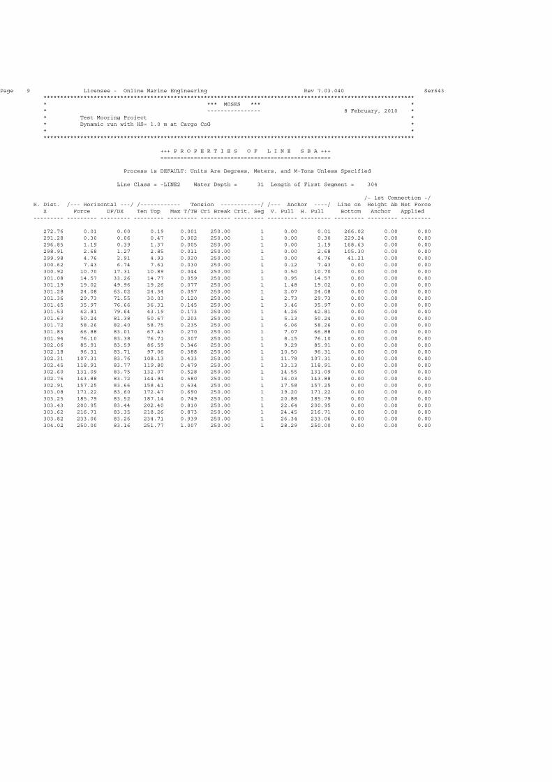
+++ P R O P E R T I E S O F L I N E S B A +++ ===================================================
Process is DEFAULT: Units Are Degrees, Meters, and M-Tons Unless Specified
Line Class = ~LINE2 Water Depth = 31 Length of First Segment = 304
/- 1st Connection -/ H. Dist. /--- Horizontal ---/ /------------ Tension ------------/ /--- Anchor ----/ Line on Height Ab Net Force X Force DF/DX Ten Top Max T/TB Cri Break Crit. Seg V. Pull H. Pull Bottom Anchor Applied --------- --------- --------- --------- --------- --------- --------- --------- --------- --------- --------- ---------
272.76 0.01 0.00 0.19 0.001 250.00 1 0.00 0.01 266.02 0.00 0.00 291.28 0.30 0.06 0.47 0.002 250.00 1 0.00 0.30 229.24 0.00 0.00 296.85 1.19 0.39 1.37 0.005 250.00 1 0.00 1.19 168.63 0.00 0.00 298.91 2.68 1.27 2.85 0.011 250.00 1 0.00 2.68 105.30 0.00 0.00 299.98 4.76 2.91 4.93 0.020 250.00 1 0.00 4.76 41.21 0.00 0.00 300.62 7.43 6.74 7.61 0.030 250.00 1 0.12 7.43 0.00 0.00 0.00 300.92 10.70 17.31 10.89 0.044 250.00 1 0.50 10.70 0.00 0.00 0.00 301.08 14.57 33.26 14.77 0.059 250.00 1 0.95 14.57 0.00 0.00 0.00 301.19 19.02 49.96 19.26 0.077 250.00 1 1.48 19.02 0.00 0.00 0.00 301.28 24.08 63.02 24.34 0.097 250.00 1 2.07 24.08 0.00 0.00 0.00 301.36 29.73 71.55 30.03 0.120 250.00 1 2.73 29.73 0.00 0.00 0.00 301.45 35.97 76.66 36.31 0.145 250.00 1 3.46 35.97 0.00 0.00 0.00 301.53 42.81 79.64 43.19 0.173 250.00 1 4.26 42.81 0.00 0.00 0.00 301.63 50.24 81.38 50.67 0.203 250.00 1 5.13 50.24 0.00 0.00 0.00 301.72 58.26 82.40 58.75 0.235 250.00 1 6.06 58.26 0.00 0.00 0.00 301.83 66.88 83.01 67.43 0.270 250.00 1 7.07 66.88 0.00 0.00 0.00 301.94 76.10 83.38 76.71 0.307 250.00 1 8.15 76.10 0.00 0.00 0.00 302.06 85.91 83.59 86.59 0.346 250.00 1 9.29 85.91 0.00 0.00 0.00 302.18 96.31 83.71 97.06 0.388 250.00 1 10.50 96.31 0.00 0.00 0.00 302.31 107.31 83.76 108.13 0.433 250.00 1 11.78 107.31 0.00 0.00 0.00 302.45 118.91 83.77 119.80 0.479 250.00 1 13.13 118.91 0.00 0.00 0.00 302.60 131.09 83.75 132.07 0.528 250.00 1 14.55 131.09 0.00 0.00 0.00 302.75 143.88 83.72 144.94 0.580 250.00 1 16.03 143.88 0.00 0.00 0.00 302.91 157.25 83.66 158.41 0.634 250.00 1 17.58 157.25 0.00 0.00 0.00 303.08 171.22 83.60 172.47 0.690 250.00 1 19.20 171.22 0.00 0.00 0.00 303.25 185.79 83.52 187.14 0.749 250.00 1 20.88 185.79 0.00 0.00 0.00 303.43 200.95 83.44 202.40 0.810 250.00 1 22.64 200.95 0.00 0.00 0.00 303.62 216.71 83.35 218.26 0.873 250.00 1 24.45 216.71 0.00 0.00 0.00 303.82 233.06 83.26 234.71 0.939 250.00 1 26.34 233.06 0.00 0.00 0.00 304.02 250.00 83.16 251.77 1.007 250.00 1 28.29 250.00 0.00 0.00 0.00

Page 10 Licensee - Online Marine Engineering Rev 7.03.040 Ser643 *************************************************************************************************************** * *** MOSES *** * * ---------------- 8 February, 2010 * * Test Mooring Project * * Dynamic run with HS= 1.0 m at Cargo CoG * * * ***************************************************************************************************************
+++ P R O P E R T I E S O F L I N E P S F +++ ===================================================
Process is DEFAULT: Units Are Degrees, Meters, and M-Tons Unless Specified
Line Class = ~LINE2 Water Depth = 31 Length of First Segment = 304
/- 1st Connection -/ H. Dist. /--- Horizontal ---/ /------------ Tension ------------/ /--- Anchor ----/ Line on Height Ab Net Force X Force DF/DX Ten Top Max T/TB Cri Break Crit. Seg V. Pull H. Pull Bottom Anchor Applied --------- --------- --------- --------- --------- --------- --------- --------- --------- --------- --------- ---------
272.76 0.01 0.00 0.19 0.001 250.00 1 0.00 0.01 266.02 0.00 0.00 291.28 0.30 0.06 0.47 0.002 250.00 1 0.00 0.30 229.24 0.00 0.00 296.85 1.19 0.39 1.37 0.005 250.00 1 0.00 1.19 168.63 0.00 0.00 298.91 2.68 1.27 2.85 0.011 250.00 1 0.00 2.68 105.30 0.00 0.00 299.98 4.76 2.91 4.93 0.020 250.00 1 0.00 4.76 41.21 0.00 0.00 300.62 7.43 6.74 7.61 0.030 250.00 1 0.12 7.43 0.00 0.00 0.00 300.92 10.70 17.31 10.89 0.044 250.00 1 0.50 10.70 0.00 0.00 0.00 301.08 14.57 33.26 14.77 0.059 250.00 1 0.95 14.57 0.00 0.00 0.00 301.19 19.02 49.96 19.26 0.077 250.00 1 1.48 19.02 0.00 0.00 0.00 301.28 24.08 63.02 24.34 0.097 250.00 1 2.07 24.08 0.00 0.00 0.00 301.36 29.73 71.55 30.03 0.120 250.00 1 2.73 29.73 0.00 0.00 0.00 301.45 35.97 76.66 36.31 0.145 250.00 1 3.46 35.97 0.00 0.00 0.00 301.53 42.81 79.64 43.19 0.173 250.00 1 4.26 42.81 0.00 0.00 0.00 301.63 50.24 81.38 50.67 0.203 250.00 1 5.13 50.24 0.00 0.00 0.00 301.72 58.26 82.40 58.75 0.235 250.00 1 6.06 58.26 0.00 0.00 0.00 301.83 66.88 83.01 67.43 0.270 250.00 1 7.07 66.88 0.00 0.00 0.00 301.94 76.10 83.38 76.71 0.307 250.00 1 8.15 76.10 0.00 0.00 0.00 302.06 85.91 83.59 86.59 0.346 250.00 1 9.29 85.91 0.00 0.00 0.00 302.18 96.31 83.71 97.06 0.388 250.00 1 10.50 96.31 0.00 0.00 0.00 302.31 107.31 83.76 108.13 0.433 250.00 1 11.78 107.31 0.00 0.00 0.00 302.45 118.91 83.77 119.80 0.479 250.00 1 13.13 118.91 0.00 0.00 0.00 302.60 131.09 83.75 132.07 0.528 250.00 1 14.55 131.09 0.00 0.00 0.00 302.75 143.88 83.72 144.94 0.580 250.00 1 16.03 143.88 0.00 0.00 0.00 302.91 157.25 83.66 158.41 0.634 250.00 1 17.58 157.25 0.00 0.00 0.00 303.08 171.22 83.60 172.47 0.690 250.00 1 19.20 171.22 0.00 0.00 0.00 303.25 185.79 83.52 187.14 0.749 250.00 1 20.88 185.79 0.00 0.00 0.00 303.43 200.95 83.44 202.40 0.810 250.00 1 22.64 200.95 0.00 0.00 0.00 303.62 216.71 83.35 218.26 0.873 250.00 1 24.45 216.71 0.00 0.00 0.00 303.82 233.06 83.26 234.71 0.939 250.00 1 26.34 233.06 0.00 0.00 0.00 304.02 250.00 83.16 251.77 1.007 250.00 1 28.29 250.00 0.00 0.00 0.00

Page 11 Licensee - Online Marine Engineering Rev 7.03.040 Ser643 *************************************************************************************************************** * *** MOSES *** * * ---------------- 8 February, 2010 * * Test Mooring Project * * Dynamic run with HS= 1.0 m at Cargo CoG * * * ***************************************************************************************************************
+++ P R O P E R T I E S O F L I N E P S A +++ ===================================================
Process is DEFAULT: Units Are Degrees, Meters, and M-Tons Unless Specified
Line Class = ~LINE1 Water Depth = 31 Length of First Segment = 153
/- 1st Connection -/ H. Dist. /--- Horizontal ---/ /------------ Tension ------------/ /--- Anchor ----/ Line on Height Ab Net Force X Force DF/DX Ten Top Max T/TB Cri Break Crit. Seg V. Pull H. Pull Bottom Anchor Applied --------- --------- --------- --------- --------- --------- --------- --------- --------- --------- --------- ---------
145.02 0.01 0.00 0.41 0.002 250.00 1 0.00 0.01 123.53 25.00 0.51 269.17 0.30 0.01 0.51 0.002 250.00 1 0.00 0.30 94.26 25.00 0.68 295.81 1.19 0.18 1.28 0.005 250.00 2 0.00 1.19 47.27 25.00 0.91 299.14 2.68 1.14 2.73 0.011 250.00 2 0.01 2.68 0.00 25.00 1.11 299.97 4.76 5.93 4.81 0.020 250.00 2 0.36 4.76 0.00 25.00 1.31 300.22 7.43 18.82 7.48 0.031 250.00 2 0.81 7.43 0.00 25.00 1.58 300.34 10.70 38.94 10.76 0.044 250.00 2 1.36 10.70 0.00 25.00 1.91 300.42 14.57 57.72 14.63 0.059 250.00 2 2.01 14.57 0.00 25.00 2.31 300.49 19.02 69.93 19.10 0.077 250.00 2 2.77 19.02 0.00 25.00 2.76 300.56 24.08 76.61 24.16 0.098 250.00 2 3.62 24.08 0.00 25.00 3.27 300.63 29.73 80.08 29.82 0.121 250.00 2 4.57 29.73 0.00 25.00 3.84 300.71 35.97 81.89 36.08 0.146 250.00 2 5.62 35.97 0.00 25.00 4.47 300.79 42.81 82.86 42.93 0.174 250.00 2 6.77 42.81 0.00 25.00 5.16 300.88 50.24 83.38 50.38 0.204 250.00 2 8.03 50.24 0.00 25.00 5.91 300.97 58.26 83.67 58.42 0.237 250.00 2 9.38 58.26 0.00 25.00 6.72 301.08 66.88 83.82 67.06 0.272 250.00 2 10.83 66.88 0.00 25.00 7.59 301.19 76.10 83.89 76.30 0.309 250.00 2 12.38 76.10 0.00 25.00 8.52 301.30 85.91 83.91 86.13 0.349 250.00 2 14.02 85.91 0.00 25.00 9.50 301.43 96.31 83.90 96.56 0.391 250.00 2 15.77 96.31 0.00 25.00 10.55 301.56 107.31 83.87 107.58 0.436 250.00 2 17.61 107.31 0.00 25.00 11.65 301.70 118.91 83.82 119.20 0.483 250.00 2 19.55 118.91 0.00 25.00 12.82 301.84 131.09 83.76 131.42 0.532 250.00 2 21.59 131.09 0.00 25.00 14.04 302.00 143.88 83.69 144.23 0.584 250.00 2 23.73 143.88 0.00 25.00 15.32 302.16 157.25 83.62 157.64 0.638 250.00 2 25.96 157.25 0.00 25.00 16.66 302.32 171.22 83.54 171.64 0.695 250.00 2 28.30 171.22 0.00 25.00 18.05 302.50 185.79 83.45 186.24 0.754 250.00 2 30.72 185.79 0.00 25.00 19.51 302.68 200.95 83.36 201.43 0.815 250.00 2 33.25 200.95 0.00 25.00 21.02 302.87 216.71 83.27 217.22 0.879 250.00 2 35.86 216.71 0.00 25.00 22.59 303.06 233.06 83.17 233.61 0.946 250.00 2 38.58 233.06 0.00 25.00 24.22 303.27 250.00 83.06 250.59 1.014 250.00 2 41.39 250.00 0.00 25.00 25.90
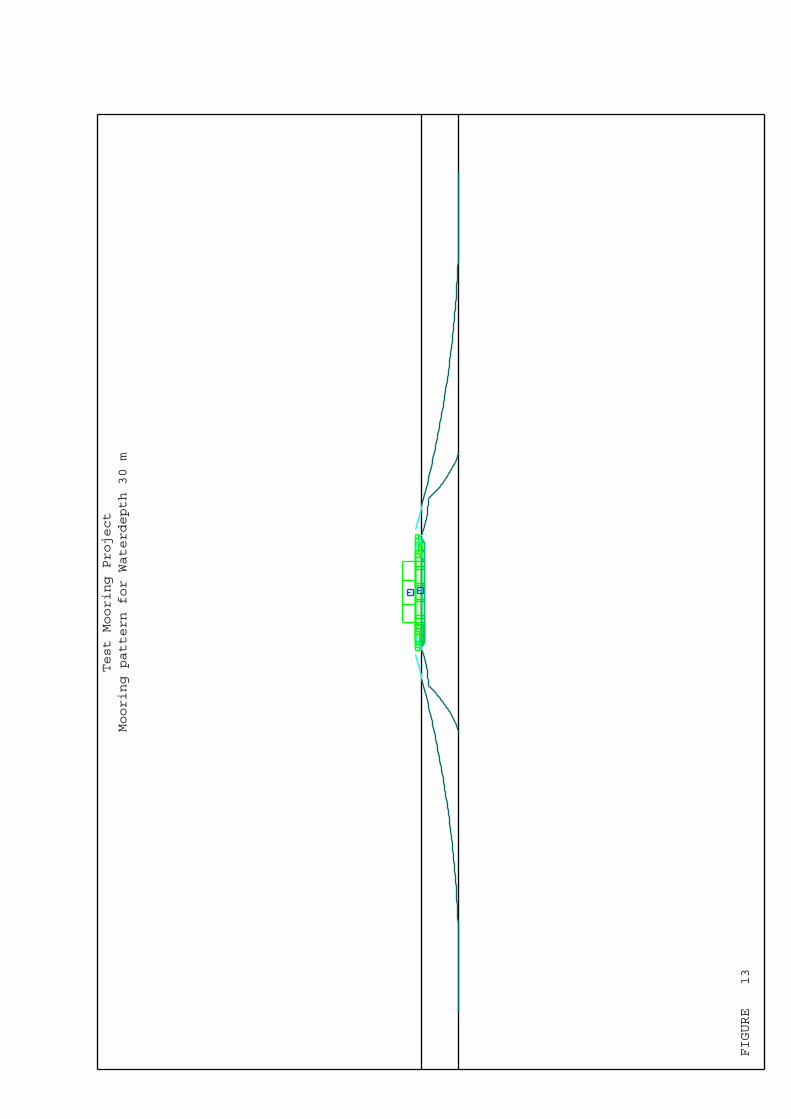
FIGURE 13
Test Mooring Project
Mooring pattern for Waterdepth 30 m
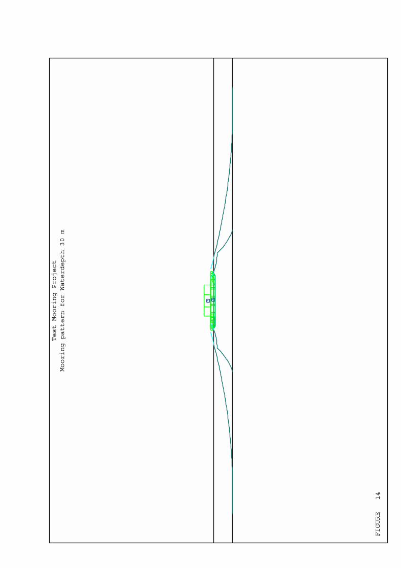
FIGURE 14
Test Mooring Project
Mooring pattern for Waterdepth 30 m
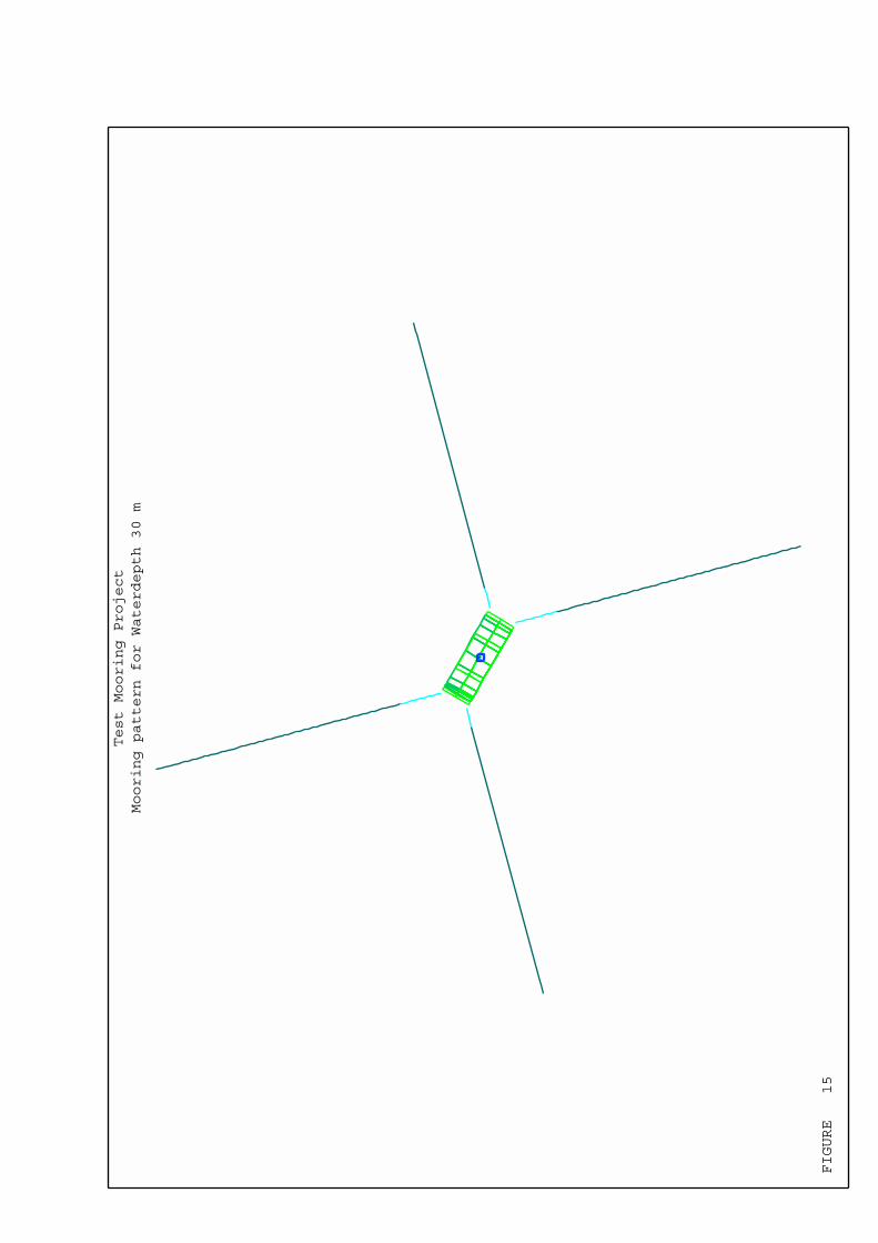
FIGURE 15
Test Mooring Project
Mooring pattern for Waterdepth 30 m

FIGURE 16
Test Mooring Project
Mooring pattern for Waterdepth 30 m
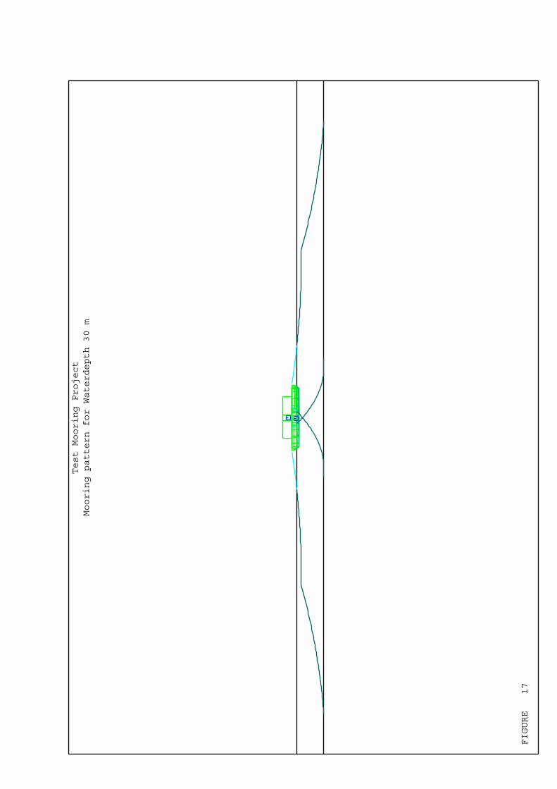
FIGURE 17
Test Mooring Project
Mooring pattern for Waterdepth 30 m

FIGURE 18
Surge
Sway
Heave
Roll
Pitch
Yaw
Response Amplitude Operators Heading 270 = Cargo CoG
14.9
8.8
12.7
16.6
20.5
24.4
28.3
32.2
36.1
40
Period (s)
00.581.161.742.322.93.484.064.645.225.8m/m
00.250.50.7511.251.51.7522.252.5Deg/m
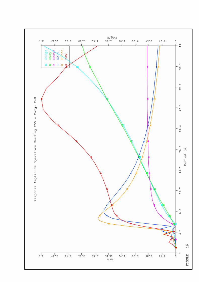
FIGURE 19
Surge
Sway
Heave
Roll
Pitch
Yaw
Response Amplitude Operators Heading 255 = Cargo CoG
14.9
8.8
12.7
16.6
20.5
24.4
28.3
32.2
36.1
40
Period (s)
00.430.861.291.722.152.583.013.443.874.3m/m
00.270.540.811.081.351.621.892.162.432.7Deg/m

FIGURE 20
Surge
Sway
Heave
Roll
Pitch
Yaw
Response Amplitude Operators Heading 240 = Cargo CoG
14.9
8.8
12.7
16.6
20.5
24.4
28.3
32.2
36.1
40
Period (s)
00.420.841.261.682.12.522.943.363.784.2m/m
00.260.520.781.041.31.561.822.082.342.6Deg/m

FIGURE 21
Surge
Sway
Heave
Roll
Pitch
Yaw
Response Amplitude Operators Heading 225 = Cargo CoG
14.9
8.8
12.7
16.6
20.5
24.4
28.3
32.2
36.1
40
Period (s)
00.470.941.411.882.352.823.293.764.234.7m/m
00.250.50.7511.251.51.7522.252.5Deg/m

FIGURE 22
Surge
Sway
Heave
Roll
Pitch
Yaw
Response Amplitude Operators Heading 210 = Cargo CoG
14.9
8.8
12.7
16.6
20.5
24.4
28.3
32.2
36.1
40
Period (s)
00.470.941.411.882.352.823.293.764.234.7m/m
00.270.540.811.081.351.621.892.162.432.7Deg/m

FIGURE 23
Surge
Sway
Heave
Roll
Pitch
Yaw
Response Amplitude Operators Heading 195 = Cargo CoG
14.9
8.8
12.7
16.6
20.5
24.4
28.3
32.2
36.1
40
Period (s)
00.440.881.321.762.22.643.083.523.964.4m/m
00.250.50.7511.251.51.7522.252.5Deg/m

FIGURE 24
Surge
Sway
Heave
Roll
Pitch
Yaw
Response Amplitude Operators Heading 180 = Cargo CoG
14.9
8.8
12.7
16.6
20.5
24.4
28.3
32.2
36.1
40
Period (s)
00.551.11.652.22.753.33.854.44.955.5m/m
00.210.420.630.841.051.261.471.681.892.1Deg/m

FIGURE 25
Surge
Sway
Heave
Roll
Pitch
Yaw
Response Amplitude Operators Heading 165 = Cargo CoG
14.9
8.8
12.7
16.6
20.5
24.4
28.3
32.2
36.1
40
Period (s)
00.651.31.952.63.253.94.555.25.856.5m/m
00.240.480.720.961.21.441.681.922.162.4Deg/m

FIGURE 26
Surge
Sway
Heave
Roll
Pitch
Yaw
Response Amplitude Operators Heading 150 = Cargo CoG
14.9
8.8
12.7
16.6
20.5
24.4
28.3
32.2
36.1
40
Period (s)
00.711.422.132.843.554.264.975.686.397.1m/m
00.210.420.630.841.051.261.471.681.892.1Deg/m
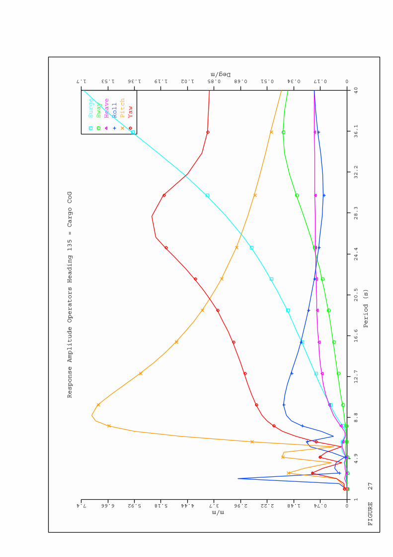
FIGURE 27
Surge
Sway
Heave
Roll
Pitch
Yaw
Response Amplitude Operators Heading 135 = Cargo CoG
14.9
8.8
12.7
16.6
20.5
24.4
28.3
32.2
36.1
40
Period (s)
00.741.482.222.963.74.445.185.926.667.4m/m
00.170.340.510.680.851.021.191.361.531.7Deg/m

FIGURE 28
Surge
Sway
Heave
Roll
Pitch
Yaw
Response Amplitude Operators Heading 120 = Cargo CoG
14.9
8.8
12.7
16.6
20.5
24.4
28.3
32.2
36.1
40
Period (s)
00.731.462.192.923.654.385.115.846.577.3m/m
00.170.340.510.680.851.021.191.361.531.7Deg/m
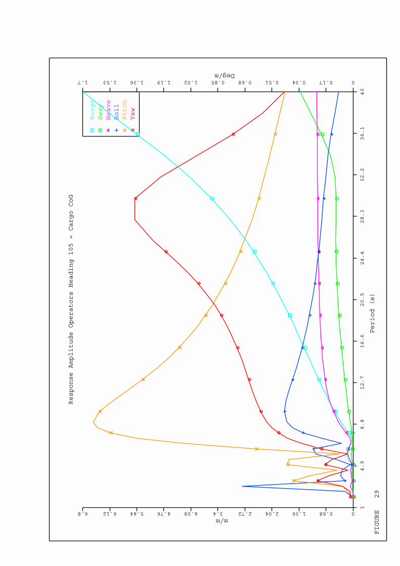
FIGURE 29
Surge
Sway
Heave
Roll
Pitch
Yaw
Response Amplitude Operators Heading 105 = Cargo CoG
14.9
8.8
12.7
16.6
20.5
24.4
28.3
32.2
36.1
40
Period (s)
00.681.362.042.723.44.084.765.446.126.8m/m
00.170.340.510.680.851.021.191.361.531.7Deg/m

FIGURE 30
Surge
Sway
Heave
Roll
Pitch
Yaw
Response Amplitude Operators Heading 090 = Cargo CoG
14.9
8.8
12.7
16.6
20.5
24.4
28.3
32.2
36.1
40
Period (s)
00.591.181.772.362.953.544.134.725.315.9m/m
00.240.480.720.961.21.441.681.922.162.4Deg/m
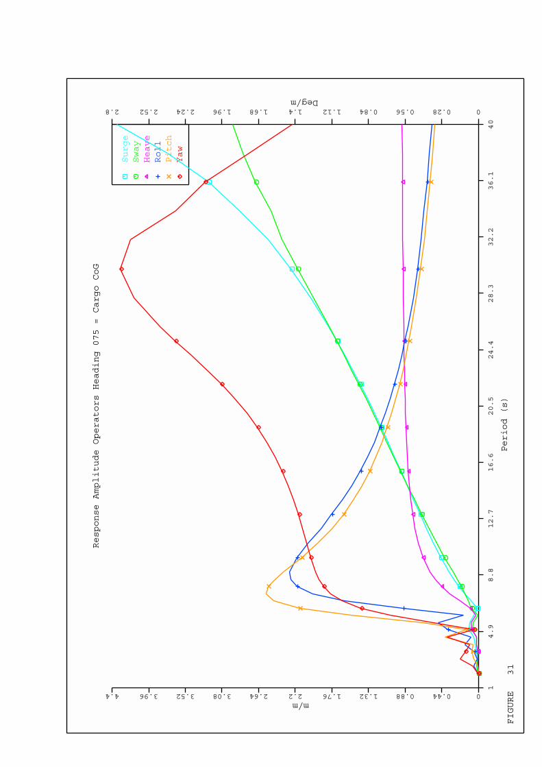
FIGURE 31
Surge
Sway
Heave
Roll
Pitch
Yaw
Response Amplitude Operators Heading 075 = Cargo CoG
14.9
8.8
12.7
16.6
20.5
24.4
28.3
32.2
36.1
40
Period (s)
00.440.881.321.762.22.643.083.523.964.4m/m
00.280.560.841.121.41.681.962.242.522.8Deg/m
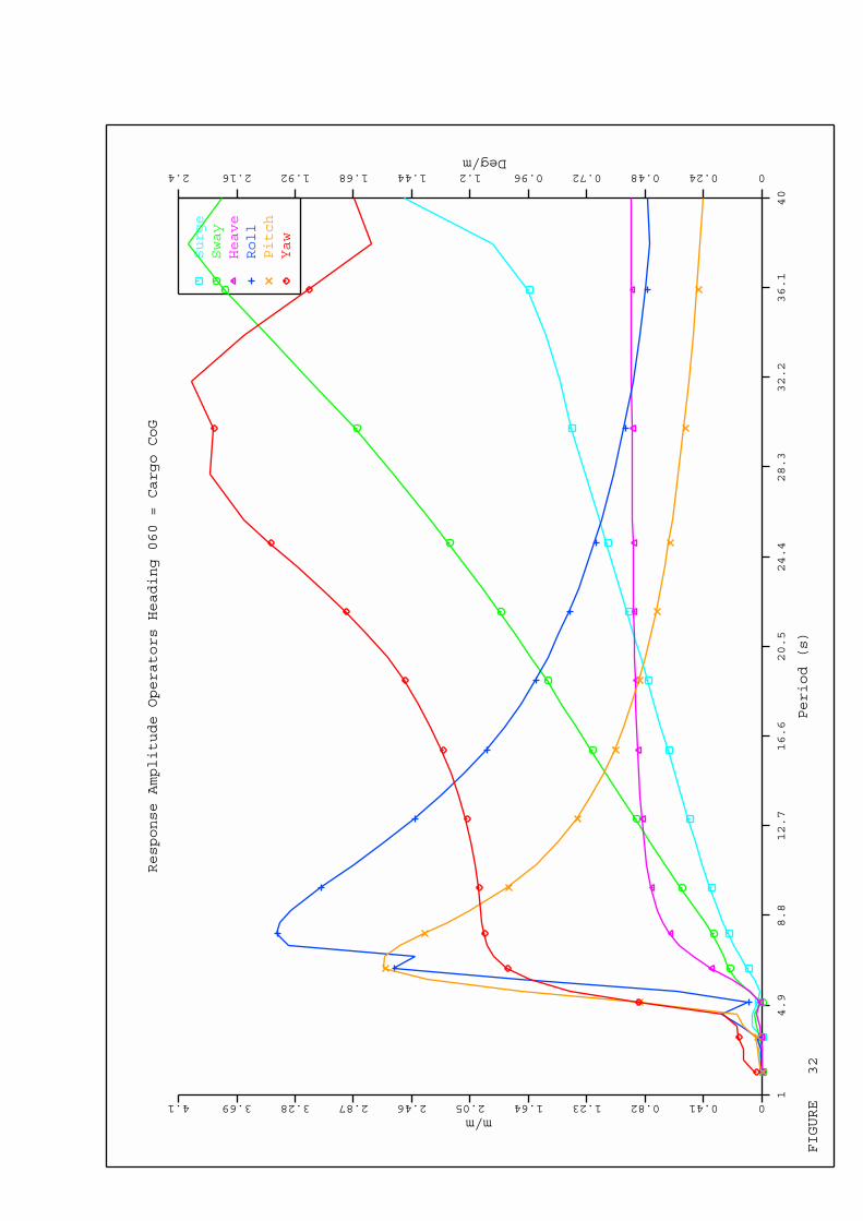
FIGURE 32
Surge
Sway
Heave
Roll
Pitch
Yaw
Response Amplitude Operators Heading 060 = Cargo CoG
14.9
8.8
12.7
16.6
20.5
24.4
28.3
32.2
36.1
40
Period (s)
00.410.821.231.642.052.462.873.283.694.1m/m
00.240.480.720.961.21.441.681.922.162.4Deg/m

FIGURE 33
Surge
Sway
Heave
Roll
Pitch
Yaw
Response Amplitude Operators Heading 045 = Cargo CoG
14.9
8.8
12.7
16.6
20.5
24.4
28.3
32.2
36.1
40
Period (s)
00.470.941.411.882.352.823.293.764.234.7m/m
00.250.50.7511.251.51.7522.252.5Deg/m

FIGURE 34
Surge
Sway
Heave
Roll
Pitch
Yaw
Response Amplitude Operators Heading 030 = Cargo CoG
14.9
8.8
12.7
16.6
20.5
24.4
28.3
32.2
36.1
40
Period (s)
00.470.941.411.882.352.823.293.764.234.7m/m
00.270.540.811.081.351.621.892.162.432.7Deg/m

FIGURE 35
Surge
Sway
Heave
Roll
Pitch
Yaw
Response Amplitude Operators Heading 015 = Cargo CoG
14.9
8.8
12.7
16.6
20.5
24.4
28.3
32.2
36.1
40
Period (s)
00.440.881.321.762.22.643.083.523.964.4m/m
00.250.50.7511.251.51.7522.252.5Deg/m

FIGURE 36
Surge
Sway
Heave
Roll
Pitch
Yaw
Response Amplitude Operators Heading 000 = Cargo CoG
14.9
8.8
12.7
16.6
20.5
24.4
28.3
32.2
36.1
40
Period (s)
00.541.081.622.162.73.243.784.324.865.4m/m
00.210.420.630.841.051.261.471.681.892.1Deg/m

FIGURE 37
Surge
Sway
Heave
Roll
Pitch
Yaw
Response Amplitude Operators Heading 345 = Cargo CoG
14.9
8.8
12.7
16.6
20.5
24.4
28.3
32.2
36.1
40
Period (s)
00.631.261.892.523.153.784.415.045.676.3m/m
00.240.480.720.961.21.441.681.922.162.4Deg/m

FIGURE 38
Surge
Sway
Heave
Roll
Pitch
Yaw
Response Amplitude Operators Heading 330 = Cargo CoG
14.9
8.8
12.7
16.6
20.5
24.4
28.3
32.2
36.1
40
Period (s)
00.691.382.072.763.454.144.835.526.216.9m/m
00.210.420.630.841.051.261.471.681.892.1Deg/m
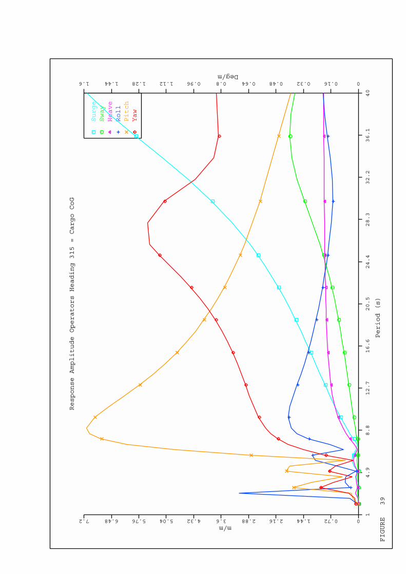
FIGURE 39
Surge
Sway
Heave
Roll
Pitch
Yaw
Response Amplitude Operators Heading 315 = Cargo CoG
14.9
8.8
12.7
16.6
20.5
24.4
28.3
32.2
36.1
40
Period (s)
00.721.442.162.883.64.325.045.766.487.2m/m
00.160.320.480.640.80.961.121.281.441.6Deg/m
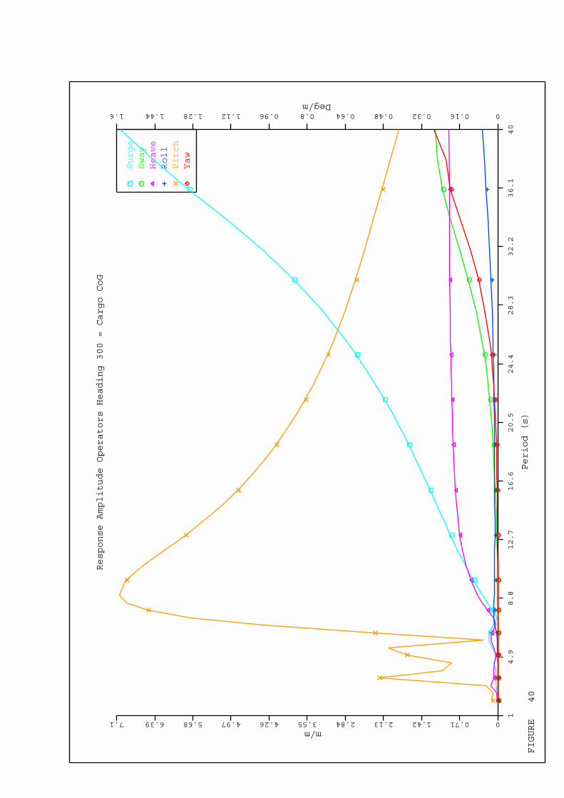
FIGURE 40
Surge
Sway
Heave
Roll
Pitch
Yaw
Response Amplitude Operators Heading 300 = Cargo CoG
14.9
8.8
12.7
16.6
20.5
24.4
28.3
32.2
36.1
40
Period (s)
00.711.422.132.843.554.264.975.686.397.1m/m
00.160.320.480.640.80.961.121.281.441.6Deg/m
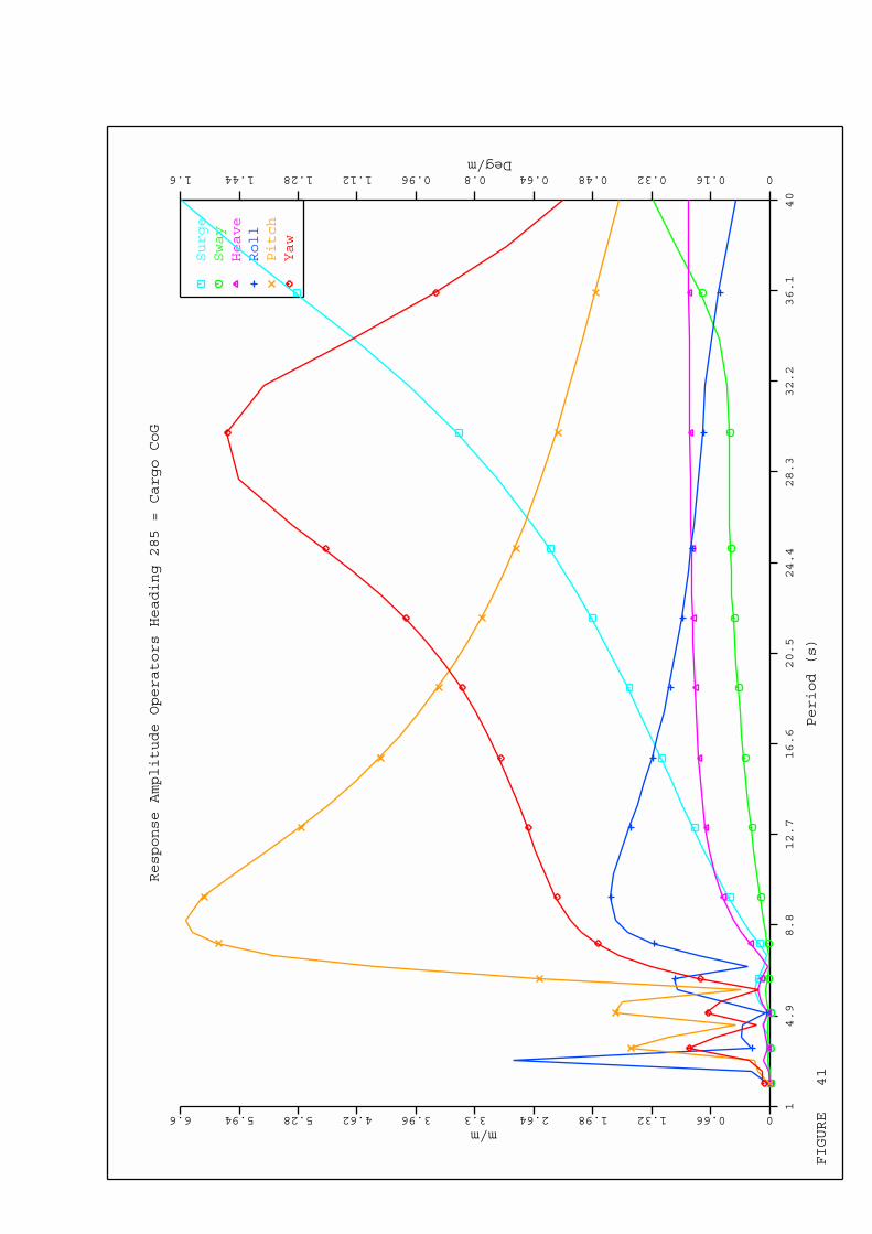
FIGURE 41
Surge
Sway
Heave
Roll
Pitch
Yaw
Response Amplitude Operators Heading 285 = Cargo CoG
14.9
8.8
12.7
16.6
20.5
24.4
28.3
32.2
36.1
40
Period (s)
00.661.321.982.643.33.964.625.285.946.6m/m
00.160.320.480.640.80.961.121.281.441.6Deg/m

Page 1 Licensee - Online Marine Engineering Rev 7.03.040 Ser643 *************************************************************************************************************** * *** MOSES *** * * ---------------- 8 February, 2010 * * Test Mooring Project Mooring analysis Waterdepth=30 m Survival+ Tmax * * SUMMARY OF Dynamic Line Utilisation factors * * * ***************************************************************************************************************
+++ S E L E C T E D V A L U E S +++ =====================================
Heading E1 T+ C1 E1 T+ C2 E1 T- C1 E1 T- C2 E2 T+ C1 E2 T+ C2 E2 T- C1 E2 T- C2 --------- --------- --------- --------- --------- --------- --------- --------- ---------
0.00 3.00 3.00 1.43 1.75 1.56 1.65 1.09 0.85 15.00 3.00 3.00 1.64 1.91 1.86 2.06 1.14 1.16 30.00 3.00 3.00 2.46 2.68 2.87 3.18 1.64 2.02 45.00 3.00 3.00 1.74 2.22 1.71 1.96 1.01 1.35 60.00 3.00 3.00 1.57 2.08 1.45 1.75 0.90 1.19 75.00 3.00 3.00 1.60 2.10 1.59 1.79 1.25 1.40 90.00 3.00 3.00 1.89 2.16 1.95 2.06 1.14 1.20 105.00 3.00 3.00 2.28 2.52 2.58 2.80 1.17 1.65 120.00 3.00 3.00 3.00 3.00 4.00 4.00 2.00 2.34 135.00 3.00 3.00 2.62 2.63 3.04 3.07 1.60 1.38 150.00 3.00 3.00 2.07 1.74 2.32 2.14 1.42 1.03 165.00 3.00 3.00 1.79 1.52 1.76 1.61 0.95 0.93 180.00 3.00 3.00 1.74 1.42 1.64 1.56 0.88 1.09 195.00 3.00 3.00 1.92 1.71 2.10 1.93 1.17 1.15 210.00 3.00 3.00 2.73 2.52 3.12 2.93 2.10 1.70 225.00 3.00 3.00 2.23 1.71 1.92 1.65 1.34 1.00 240.00 3.00 3.00 2.12 1.63 1.77 1.47 1.30 0.89 255.00 3.00 3.00 2.09 1.64 1.83 1.59 1.34 1.22 270.00 3.00 3.00 2.20 1.90 2.11 1.98 1.21 1.18 285.00 3.00 3.00 2.56 2.32 2.86 2.63 1.65 1.19 300.00 3.00 3.00 3.00 3.00 4.00 3.75 2.32 1.81 315.00 3.00 3.00 2.73 2.27 3.01 2.61 1.46 1.53 330.00 3.00 3.00 1.74 2.10 2.10 2.39 1.02 1.38 345.00 3.00 3.00 1.53 1.80 1.59 1.79 0.90 0.93
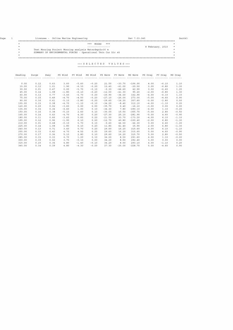
Page 1 Licensee - Online Marine Engineering Rev 7.03.040 Ser643 *************************************************************************************************************** * *** MOSES *** * * ---------------- 8 February, 2010 * * Test Mooring Project Mooring analysis Waterdepth=30 m * * SUMMARY OF ENVIRONMENTAL FORCES - Operational Tmin Cur Dir 45 * * * ***************************************************************************************************************
+++ S E L E C T E D V A L U E S +++ =====================================
Heading Surge Sway FX Wind FY Wind MZ Wind FX Wave FY Wave MZ Wave FX Drag FY Drag MZ Drag --------- --------- --------- --------- --------- --------- --------- --------- --------- --------- --------- ---------
0.00 0.12 0.63 3.60 -5.60 -0.20 21.50 -33.70 -106.90 4.00 -6.10 1.10 15.00 0.12 1.01 1.90 -6.10 -0.20 12.40 -41.00 -20.50 2.00 -6.80 1.30 30.00 0.01 0.47 0.00 -5.70 -0.10 -0.30 -44.60 42.90 0.00 -6.60 1.20 45.00 0.14 1.08 -1.80 -6.10 -0.20 -12.00 -41.30 95.20 -2.00 -6.80 1.30 60.00 0.13 0.77 -3.50 -5.70 -0.20 -20.90 -34.50 162.90 -4.00 -6.10 1.10 75.00 0.15 0.49 -4.70 -4.50 -0.20 -27.10 -26.00 273.00 -5.00 -4.60 0.90 90.00 0.16 0.41 -5.10 -2.80 -0.20 -29.60 -16.20 357.60 -5.00 -2.80 0.50 105.00 0.15 0.38 -4.70 -1.10 -0.10 -34.20 -8.40 312.10 -4.00 -1.10 0.20 120.00 0.15 0.02 -3.60 0.00 0.00 -35.70 0.40 -16.10 -3.00 0.00 0.00 135.00 0.15 0.34 -4.60 1.00 0.10 -34.30 7.80 -290.10 -4.00 1.10 -0.20 150.00 0.16 0.38 -5.10 2.60 0.10 -30.00 15.50 -355.70 -5.00 2.80 -0.50 165.00 0.14 0.43 -4.70 4.30 0.20 -27.30 25.10 -281.90 -5.00 4.60 -0.90 180.00 0.11 0.66 -3.60 5.60 0.20 -21.50 33.70 -173.20 -4.00 6.10 -1.10 195.00 0.12 0.96 -1.90 6.10 0.20 -12.70 40.80 -100.40 -2.00 6.80 -1.30 210.00 0.01 0.48 -0.10 5.70 0.10 -0.60 44.50 -44.30 0.00 6.60 -1.20 225.00 0.14 1.08 1.80 6.10 0.20 11.80 41.40 15.90 2.00 6.80 -1.30 240.00 0.13 0.71 3.40 5.70 0.20 29.60 16.20 315.60 4.00 6.10 -1.10 255.00 0.15 0.42 4.70 4.50 0.20 29.60 16.20 315.60 5.00 4.60 -0.90 270.00 0.17 0.36 5.10 2.80 0.10 29.60 16.20 315.70 5.00 2.80 -0.50 285.00 0.15 0.33 4.70 1.20 0.10 34.20 8.50 291.60 4.00 1.10 -0.20 300.00 0.15 0.02 3.70 -0.10 0.00 34.20 8.50 292.40 3.00 0.00 0.00 315.00 0.15 0.34 4.80 -1.40 -0.10 34.20 8.50 293.10 4.00 -1.10 0.20 345.00 0.14 0.39 4.80 -4.30 -0.20 27.30 -25.00 -228.70 5.00 -4.60 0.90

Page 2 Licensee - Online Marine Engineering Rev 7.03.040 Ser643 *************************************************************************************************************** * *** MOSES *** * * ---------------- 8 February, 2010 * * Test Mooring Project Mooring analysis Waterdepth=30 m * * SUMMARY OF ENVIRONMENTAL FORCES - Operational Tmax Cur Dir 45 * * * ***************************************************************************************************************
+++ S E L E C T E D V A L U E S +++ =====================================
Heading Surge Sway FX Wind FY Wind MZ Wind FX Wave FY Wave MZ Wave FX Drag FY Drag MZ Drag --------- --------- --------- --------- --------- --------- --------- --------- --------- --------- --------- ---------
0.00 0.56 1.94 3.50 -5.70 -0.20 4.90 -8.10 -5.40 4.00 -6.10 1.10 15.00 0.47 2.00 1.70 -6.10 -0.20 3.50 -12.30 3.30 2.00 -6.80 1.30 30.00 0.08 1.47 0.00 -5.60 -0.10 -0.20 -29.00 27.80 0.00 -6.60 1.20 45.00 0.38 1.64 -1.70 -6.10 -0.20 -3.90 -13.70 22.50 -2.00 -6.80 1.30 60.00 0.48 2.31 -3.40 -5.70 -0.20 -5.80 -9.80 25.20 -4.00 -6.10 1.10 75.00 0.48 2.57 -4.60 -4.50 -0.20 -8.30 -8.10 33.40 -5.00 -4.60 0.90 90.00 0.55 2.62 -5.10 -2.80 -0.20 -13.60 -7.60 49.50 -5.00 -2.80 0.50 105.00 0.80 1.83 -4.70 -1.20 -0.10 -21.50 -5.40 51.40 -4.00 -1.10 0.20 120.00 1.07 0.15 -3.60 0.10 0.00 -37.80 0.50 -4.80 -3.00 0.00 0.00 135.00 0.88 1.86 -4.70 1.20 0.10 -28.40 7.10 -67.50 -4.00 1.10 -0.20 150.00 0.68 2.34 -5.10 2.80 0.10 -16.30 8.90 -58.50 -5.00 2.80 -0.50 165.00 0.64 2.30 -4.70 4.40 0.20 -10.50 9.90 -42.00 -5.00 4.60 -0.90 180.00 0.63 2.22 -3.50 5.60 0.20 -7.40 11.90 -31.80 -4.00 6.10 -1.10 195.00 0.56 2.08 -1.80 6.10 0.20 -5.00 16.70 -28.20 -2.00 6.80 -1.30 210.00 0.11 1.63 -0.10 5.70 0.10 -0.50 35.40 -34.70 0.00 6.60 -1.20 225.00 0.47 2.68 1.70 6.10 0.20 6.30 22.60 -6.30 2.00 6.80 -1.30 240.00 0.65 2.91 3.40 5.70 0.30 17.20 9.60 41.70 4.00 6.10 -1.10 255.00 0.70 2.56 4.60 4.50 0.20 16.60 9.30 40.30 5.00 4.60 -0.90 270.00 0.75 2.06 5.10 2.90 0.10 18.50 10.30 44.90 5.00 2.80 -0.50 285.00 0.88 1.25 4.70 1.20 0.10 26.90 7.00 50.90 4.00 1.10 -0.20 300.00 1.04 0.17 3.60 0.00 0.00 37.10 9.50 68.90 3.00 0.00 0.00 315.00 0.90 1.56 4.70 -1.30 -0.10 30.70 8.10 59.00 4.00 -1.10 0.20 345.00 0.61 1.86 4.70 -4.40 -0.20 7.70 -7.20 -15.90 5.00 -4.60 0.90
Page 3 Licensee - Online Marine Engineering Rev 7.03.040 Ser643 *************************************************************************************************************** * *** MOSES *** * * ---------------- 8 February, 2010 * * Test Mooring Project Mooring analysis Waterdepth=30 m * * SUMMARY OF ENVIRONMENTAL FORCES - Survival Tmin Cur Dir 45 * * * ***************************************************************************************************************
+++ S E L E C T E D V A L U E S +++ =====================================
Heading Surge Sway FX Wind FY Wind MZ Wind FX Wave FY Wave MZ Wave FX Drag FY Drag MZ Drag --------- --------- --------- --------- --------- --------- --------- --------- --------- --------- --------- ---------
0.00 0.47 2.43 14.20 -22.40 -0.90 6.30 -10.00 -9.40 4.00 -6.10 1.10 15.00 0.41 2.35 7.30 -24.50 -0.80 4.90 -16.30 2.40 2.00 -6.80 1.30 30.00 0.03 1.46 -0.10 -22.60 -0.30 -0.30 -41.30 39.80 0.00 -6.60 1.20 45.00 0.33 1.68 -7.10 -24.50 -0.80 -4.00 -13.90 24.10 -2.00 -6.80 1.30 60.00 0.32 2.24 -13.70 -22.70 -0.90 -5.30 -8.80 24.50 -4.00 -6.10 1.10 75.00 0.32 2.55 -18.60 -17.90 -0.80 -8.60 -8.30 38.10 -5.00 -4.60 0.90 90.00 0.43 2.48 -20.40 -11.20 -0.60 -15.40 -8.50 62.60 -5.00 -2.80 0.50 105.00 0.69 1.82 -18.60 -4.60 -0.30 -29.00 -7.20 78.30 -4.00 -1.10 0.20 120.00 1.06 0.18 -14.60 0.20 0.00 -70.80 1.10 -11.60 -3.00 0.00 0.00 135.00 0.81 1.62 -18.40 4.20 0.20 -40.10 9.20 -101.10 -4.00 1.10 -0.20 150.00 0.61 2.47 -20.40 10.60 0.50 -21.80 11.40 -86.20 -5.00 2.80 -0.50 165.00 0.47 2.45 -18.90 17.30 0.70 -10.80 9.90 -47.20 -5.00 4.60 -0.90 180.00 0.48 2.29 -14.30 22.40 0.90 -7.00 11.00 -32.10 -4.00 6.10 -1.10 195.00 0.47 2.05 -7.60 24.50 0.80 -6.40 20.70 -37.40 -2.00 6.80 -1.30 210.00 0.04 1.57 -0.30 22.70 0.50 -0.70 48.80 -47.90 0.00 6.60 -1.20 225.00 0.39 2.43 7.00 24.50 0.90 5.00 17.60 -3.40 2.00 6.80 -1.30 240.00 0.41 2.98 13.70 22.70 1.00 12.60 7.00 36.20 4.00 6.10 -1.10 255.00 0.44 2.75 18.60 17.90 0.90 13.50 7.50 38.70 5.00 4.60 -0.90 270.00 0.54 2.18 20.40 11.30 0.60 17.90 9.90 51.30 5.00 2.80 -0.50 285.00 0.77 1.30 18.70 4.60 0.30 35.50 8.90 76.40 4.00 1.10 -0.20 300.00 1.15 0.30 14.80 -0.40 -0.10 69.60 16.90 145.50 3.00 0.00 0.00 315.00 0.79 1.40 18.90 -5.10 -0.50 39.30 10.50 90.50 4.00 -1.10 0.20 345.00 0.43 2.26 18.90 -17.30 -0.70 8.80 -8.10 -21.90 5.00 -4.60 0.90
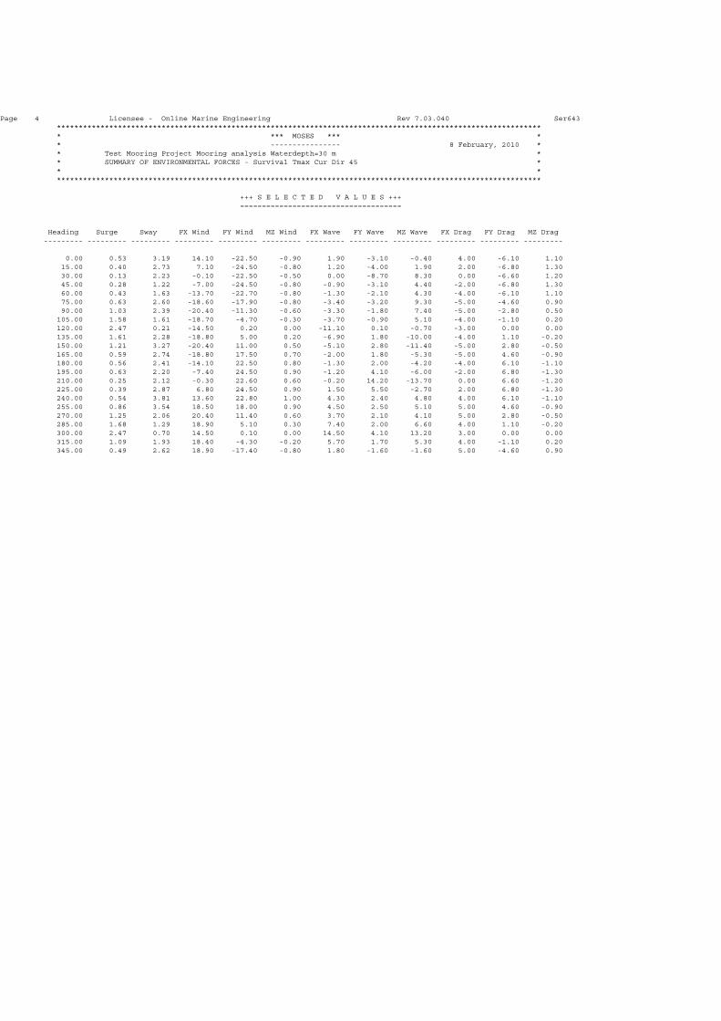
Page 4 Licensee - Online Marine Engineering Rev 7.03.040 Ser643 *************************************************************************************************************** * *** MOSES *** * * ---------------- 8 February, 2010 * * Test Mooring Project Mooring analysis Waterdepth=30 m * * SUMMARY OF ENVIRONMENTAL FORCES - Survival Tmax Cur Dir 45 * * * ***************************************************************************************************************
+++ S E L E C T E D V A L U E S +++ =====================================
Heading Surge Sway FX Wind FY Wind MZ Wind FX Wave FY Wave MZ Wave FX Drag FY Drag MZ Drag --------- --------- --------- --------- --------- --------- --------- --------- --------- --------- --------- ---------
0.00 0.53 3.19 14.10 -22.50 -0.90 1.90 -3.10 -0.40 4.00 -6.10 1.10 15.00 0.40 2.73 7.10 -24.50 -0.80 1.20 -4.00 1.90 2.00 -6.80 1.30 30.00 0.13 2.23 -0.10 -22.50 -0.50 0.00 -8.70 8.30 0.00 -6.60 1.20 45.00 0.28 1.22 -7.00 -24.50 -0.80 -0.90 -3.10 4.40 -2.00 -6.80 1.30 60.00 0.43 1.63 -13.70 -22.70 -0.80 -1.30 -2.10 4.30 -4.00 -6.10 1.10 75.00 0.63 2.60 -18.60 -17.90 -0.80 -3.40 -3.20 9.30 -5.00 -4.60 0.90 90.00 1.03 2.39 -20.40 -11.30 -0.60 -3.30 -1.80 7.40 -5.00 -2.80 0.50 105.00 1.58 1.61 -18.70 -4.70 -0.30 -3.70 -0.90 5.10 -4.00 -1.10 0.20 120.00 2.47 0.21 -14.50 0.20 0.00 -11.10 0.10 -0.70 -3.00 0.00 0.00 135.00 1.61 2.28 -18.80 5.00 0.20 -6.90 1.80 -10.00 -4.00 1.10 -0.20 150.00 1.21 3.27 -20.40 11.00 0.50 -5.10 2.80 -11.40 -5.00 2.80 -0.50 165.00 0.59 2.74 -18.80 17.50 0.70 -2.00 1.80 -5.30 -5.00 4.60 -0.90 180.00 0.56 2.41 -14.10 22.50 0.80 -1.30 2.00 -4.20 -4.00 6.10 -1.10 195.00 0.63 2.20 -7.40 24.50 0.90 -1.20 4.10 -6.00 -2.00 6.80 -1.30 210.00 0.25 2.12 -0.30 22.60 0.60 -0.20 14.20 -13.70 0.00 6.60 -1.20 225.00 0.39 2.87 6.80 24.50 0.90 1.50 5.50 -2.70 2.00 6.80 -1.30 240.00 0.54 3.81 13.60 22.80 1.00 4.30 2.40 4.80 4.00 6.10 -1.10 255.00 0.86 3.54 18.50 18.00 0.90 4.50 2.50 5.10 5.00 4.60 -0.90 270.00 1.25 2.06 20.40 11.40 0.60 3.70 2.10 4.10 5.00 2.80 -0.50 285.00 1.68 1.29 18.90 5.10 0.30 7.40 2.00 6.60 4.00 1.10 -0.20 300.00 2.47 0.70 14.50 0.10 0.00 14.50 4.10 13.20 3.00 0.00 0.00 315.00 1.09 1.93 18.40 -4.30 -0.20 5.70 1.70 5.30 4.00 -1.10 0.20 345.00 0.49 2.62 18.90 -17.40 -0.80 1.80 -1.60 -1.60 5.00 -4.60 0.90