Embed Size (px)
Citation preview
1
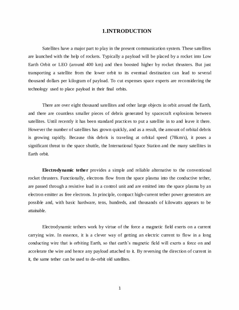
1.INTRODUCTION
Satellites have a major part to play in the present communication system. These satellites
are launched with the help of rockets. Typically a payload will be placed by a rocket into Low
Earth Orbit or LEO (around 400 km) and then boosted higher by rocket thrusters. But just
transporting a satellite from the lower orbit to its eventual destination can lead to several
thousand dollars per kilogram of payload. To cut expenses space experts are reconsidering the
technology used to place payload in their final orbits.
There are over eight thousand satellites and other large objects in orbit around the Earth,
and there are countless smaller pieces of debris generated by spacecraft explosions between
satellites. Until recently it has been standard practices to put a satellite in to and leave it there.
However the number of satellites has grown quickly, and as a result, the amount of orbital debris
is growing rapidly. Because this debris is traveling at orbital speed (78km/s), it poses a
significant threat to the space shuttle, the International Space Station and the many satellites in
Earth orbit.
Electrodynamic tether provides a simple and reliable alternative to the conventional
rocket thrusters. Functionally, electrons flow from the space plasma into the conductive tether,
are passed through a resistive load in a control unit and are emitted into the space plasma by an
electron emitter as free electrons. In principle, compact high-current tether power generators are
possible and, with basic hardware, tens, hundreds, and thousands of kilowatts appears to be
attainable.
Electrodynamic tethers work by virtue of the force a magnetic field exerts on a current
carrying wire. In essence, it is a clever way of getting an electric current to flow in a long
conducting wire that is orbiting Earth, so that earth’s magnetic field will exerts a force on and
accelerate the wire and hence any payload attached to it. By reversing the direction of current in
it, the same tether can be used to de-orbit old satellites.
2
Electrodynamic tethers have strong potential for providing propellantless propulsion to
spacecraft in low-Earth orbit for applications such as satellite de-orbit orbit boosting, and station
keeping. The tether, however, is not a rigid rod held above or below the spacecraft. It is a very
long, thin cable, and has little or no flexural rigidity. The transverse electrodynamic forces
therefore cause the tether to bow and to swing away from the local vertical. Gravity gradient
forces produce a restoring force that pulls the tether back towards the local vertical, but this
results in a pendulum-like motion. Because the direction of the geomagnetic field varies as the
tether orbits the Earth, the direction and magnitude of the electrodynamic forces also varies, and
so this pendulum motion develops into complex librations in both the in-plane and out-of-plane
directions. Due to coupling between the in plane motion and longitudinal elastic oscillations, as
well as coupling between in-plane and out-of-plane motions, an electrodynamic tether operated
at a constant current will continually add energy to the libration motions, causing the libration
amplitudes to build until the tether begins rotating or oscillating wildly. In addition, orbital
variations in the strength and magnitude of the electrodynamic force will drive transverse,
higher-order oscillations in the tether which can lead to the unstable growth of "skip-rope"
modes.
3
2. REVIEW OF EXISTING ROCKET PROPULSION MECHANISM
The existing rocket propulsion mechanism derives energy from rocket fuels. Hydrogen
peroxide is one of the commonly used rocket fuels. The disadvantage of these rocket fuels is that
it produces low thrust. Kerosene is a liquid propellant, requires cryogenic systems for their
implementation. Nuclear energy can be used as a propellant. But it produces radiations, which
are very harmful.
There are several disadvantages in dealing with liquid propulsion systems. Spills or leaks
or several hazardous problems occur in it. Usually requires more volume due to lower average
propellant density and the relatively inefficient. A few propellants give toxic vapors or fumes.
Even in solid propellant system there are many backlogs such as these propellants are
largely prone to explosion and exhaust gases are usually toxic. Some propellants or propellant
ingredients can deteriorate.
An electrodynamic tether overcoming all such difficulties and risks with its unique
features put forward is a better option.
4
3. HISTORY
Tsiolkovsky once proposed a tower so tall that it reached into space, so that it would be
held there by the rotation of the Earth. However, there was no realistic way to build it. To try to
solve the problems in Komsomolskaya Pravda, another Russian, Yuri Artsutanov, wrote in
greater detail about the idea of a tensile cable to be deployed from a geosynchronous sate llite
downwards towards the ground, and upwards away keeping the cable balanced. This is the space
elevatoridea, a type of synchronous tether that would rotate with the Earth. However, given the
materials, this too was impractical on Earth.
In the 1970s Jerome Pearson explored synchronous tethers further, and in particular
analysed the lunar elevator, and this was found to be possible with materials then existing.
In 1977 Hans Moravec and later Robert L. Forward investigated the physics of
synchronous and non synchronous skyhook tethers, and performed detailed simulations of
tapered tethers that could pick objects off and place objects onto the Moon, Mars and other
planets, with little, or even a net gain of energy.
In 1979 the USA NASA examined the feasibility of the idea and gave direction to the
study of tethered systems, especially tethered satellites. In 2000, the NASA and Boeing
considered a HASTOL concept where a tether would take payloads from a hypersonic aircraft (at
half of orbital velocity) to orbit.
Since then, a series of interesting space tether applications have been proposed and
analysed. Particularly in the last decade, the study of space tether has received significant
attention from researchers covering a broad range of applications. Some examples of
applications have considerable promise including the deployment and retrieval of subsatellites,
aerobraking, electrodynamic boost, deorbit of satellites, and momentum-transfer with libration
and rotation analysis.
5
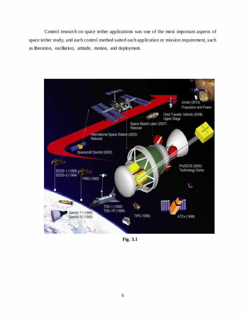
Control research on space tether applications was one of the most important aspects of
space tether study, and each control method suited each application or mission requirement, such
as liberation, oscillation, attitude, motion, and deployment.
Fig. 3.1
6
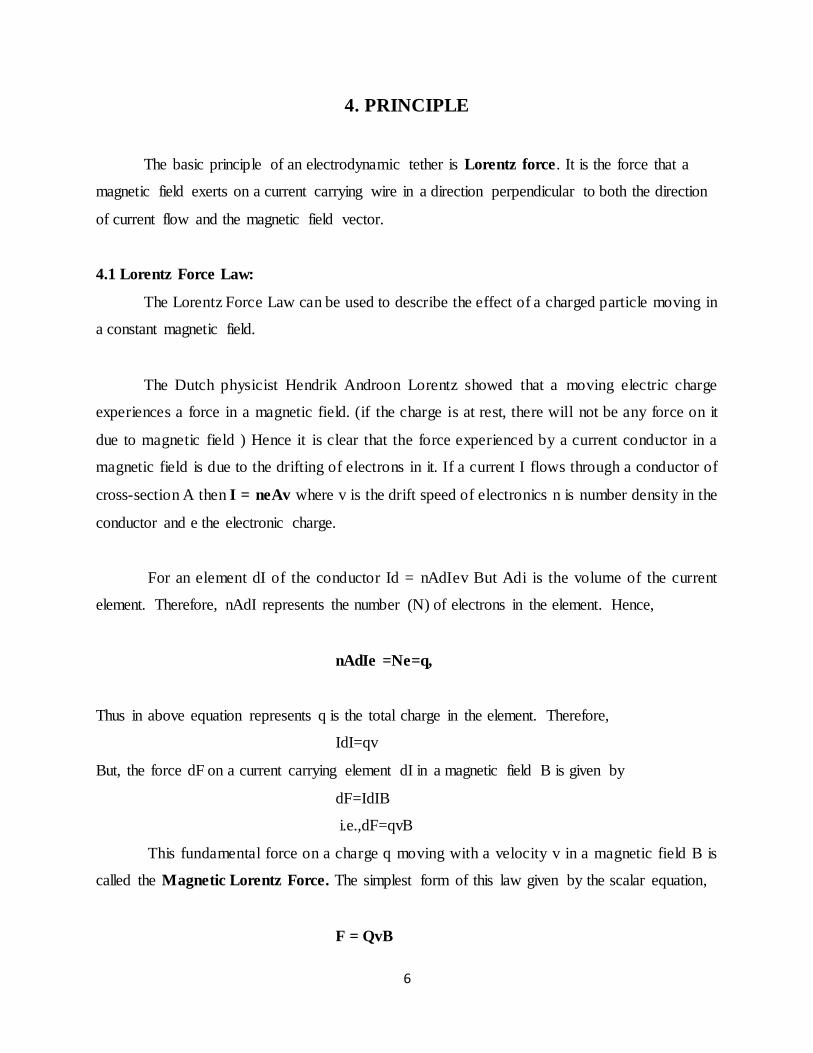
4. PRINCIPLE
The basic principle of an electrodynamic tether is Lorentz force. It is the force that a
magnetic field exerts on a current carrying wire in a direction perpendicular to both the direction
of current flow and the magnetic field vector.
4.1 Lorentz Force Law:
The Lorentz Force Law can be used to describe the effect of a charged particle moving in
a constant magnetic field.
The Dutch physicist Hendrik Androon Lorentz showed that a moving electric charge
experiences a force in a magnetic field. (if the charge is at rest, there will not be any force on it
due to magnetic field ) Hence it is clear that the force experienced by a current conductor in a
magnetic field is due to the drifting of electrons in it. If a current I flows through a conductor of
cross-section A then I = neAv where v is the drift speed of electronics n is number density in the
conductor and e the electronic charge.
For an element dI of the conductor Id = nAdIev But Adi is the volume of the current
element. Therefore, nAdI represents the number (N) of electrons in the element. Hence,
nAdIe =Ne=q,
Thus in above equation represents q is the total charge in the element. Therefore,
IdI=qv
But, the force dF on a current carrying element dI in a magnetic field B is given by
dF=IdIB
i.e.,dF=qvB
This fundamental force on a charge q moving with a velocity v in a magnetic field B is
called the Magnetic Lorentz Force. The simplest form of this law given by the scalar equation,
F = QvB
7
‘F’ is the force acting on the particle (vector)
‘V’ is the velocity of the particle (vector)
‘Q’ is charge of particle (scalar)
‘B’ is magnetic field (vector).
NOTE: In this case is for v and B perpendicular to each other otherwise use F = QvB (sin (X) )
where X is the angle between v and B, when v and B are perpendicular X =90 deg. So sin (x) =1.
Fleming’s left hand rule comes in to play here to figure out which way the force is acting.
4.2 Fleming’s Left Hand Rule:
For a charged particle moving (velocity v) in a magnetic field (field B) the direction of
the resultant force (force F) can be found by: middle finger of left hand in direction of current
index finger of left hand in direction of field B, thumb now points in direction of the force or
motion F. The force will always be perpendicular to the plane of vector v and B no matter what
the angle between v and B is.
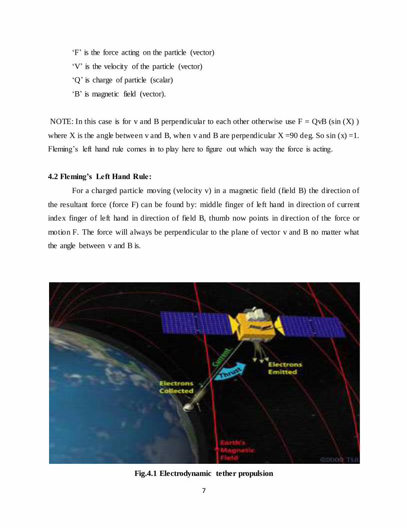
Fig.4.1 Electrodynamic tether propulsion
8
5. WORKING
Electrodynamic tethers (EDTs) are long conducting wires, such as one deployed from a
tether satellite, which can operate on electromagnetic principles, by converting their kinetic
energy to electrical energy(as generators), and vice versa (as motors). Electric potential is
generated across a conductive tether by its motion through the Earth's magnetic field.
As part of a tether propulsion system, crafts can use long, strong conductors (though not
all tethers are conductive) to change the orbits of spacecraft. The electrodynamic tether is made
from aluminium alloy and typically between 5 and 20 kilometers long. It extends downwards
from an orbiting platform. Aluminium alloy is used since it is strong, lightweight, inexpensive
and easily machined. It can be used either to accelerate or brake an orbiting spacecraft. When
direct current is pumped through the tether, it exerts a force against the magnetic field, and the
tether accelerates the spacecraft.
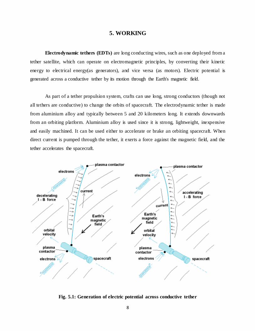
Fig. 5.1: Generation of electric potential across conductive tether
9
The gravity gradient field (also known as tidal force) will tend to orient the tether in a
vertical position. If the tether is orbiting around the Earth, it will be crossing the earth’s magnetic
field lines orbital velocity (7-8 km/s). The motion of the conductor across the magnetic field
induces a voltage along the length of the tether. The voltage thus created along its length can be
up to several hundred volts per kilometer.
In an electrodynamic tether drag system such as the terminator Tether, the tether can be
used to reduce the orbit of the spacecraft to which it is attached. If the system has a means for
collecting electrons from the ionospheric plasma at one end of the tether and expelling them back
in to the plasma at the other end of the tether, the voltage can drive a current along the tether.
This current bill, in turn, interacts with the Earth’s magnetic field to cause a Lorentz JXB force,
which will oppose the motion of the tether and whatever it is attached to. This electrodynamics
drag force will decrease the orbit of the tether and its host spacecraft. Essentially, the tether
converts the orbital energy of the host spacecraft in to electrical power, which is dissipated as
ohmic heating in the tether.
In an electrodynamic propulsion system, the tether can be used to boost the orbit of the
spacecraft. If a power supply is added to the tether system and used to drive current in the
direction opposite to that which it normally wants to flow, the tether can push against the Earth’s
magnetic field to raise the spacecraft’s orbit. The major advantage of this technique compared to
the other space propulsion system is that it doesn’t require any propellant. It uses Earth’s
magnetic field as its reaction mass. By eliminating the need to launch large amounts of
propellant in to orbit, electrodynamic tethers can greatly reduce the cost of in-space propulsion.
The tether is dragged through the atmosphere ionosheric plasma. The rarefied medium of
electrons through which the whole set up is traveling at a speed of 7-8km/s. In so doing, the 5-
km. long aluminium wire extracts electrons from the plasma at the end farthest from the payload
and carries them to the near end (plasma chamber tests have verified that thin bare wires can
collect current from plasma). There a specially designed devise known as a hollow cathode
emitter expels the electrons, to ensure their return to space currents in the circuit. Ordinarily, a
uniform magnetic field acting on a current-bearing loop of wire yields a net force of zero, since
that cancels the force on one side of the loop on the other side, in which the current is flowing in
10
the opposite direction However, since the tethered system is not mechanically attached to the
plasma. The magnetic force on the plasma current in the space does not cancel the forces on the
tether. And so the tether experiences a net force.
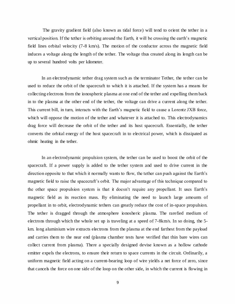
As the tether cuts across the magnetic field, its bias voltage is positive at the end farthest
from Earth and negative at the near end. This polarization is due to the action of Lorentz force on
the electrons in the tether. Thus the natural upward current flow due to the (negatively charged)
electrons in the ionosphere being attracted to the tethers far and then returned to the plasma at the
near end. Aided by, the hollow cathode emitter. The hollow cathode is vital without it, the wire’s
charge distribution would quickly reach equilibrium and no current would flow. Switching on the
hollow cathode causes a small tungsten tube to heat up and fill with xenon gas from small tank.
Electrons from the tether interacted with the heated gas to create ion plasma. At the far end of the
tube a ‘keeper electrode’ is present, which is positively charged with respect to the tube. Draw
the electrons and expels them to space. (the xenon ions, mean while are collected by the hollow
cathode and used to provide additional heating). The rapid discharge of electrons invites new
electrons to follow from the tether and out through the hollow cathode. Earth’s magnetic field
exerts a drag force on a current carrying tether, decelerating it and the payload and rapidly
lowering their orbit. Eventually they re-enter Earth’s atmosphere.
Fig. 5.2
11
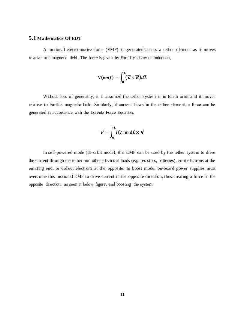
5.1 Mathematics Of EDT
A motional electromotive force (EMF) is generated across a tether element as it moves
relative to a magnetic field. The force is given by Faraday's Law of Induction,
V(𝒆𝒎𝒇) = ∫ (�⃗⃗� × �⃗⃗� )𝒅�⃗⃗� 𝑳
𝟎
Without loss of generality, it is assumed the tether system is in Earth orbit and it moves
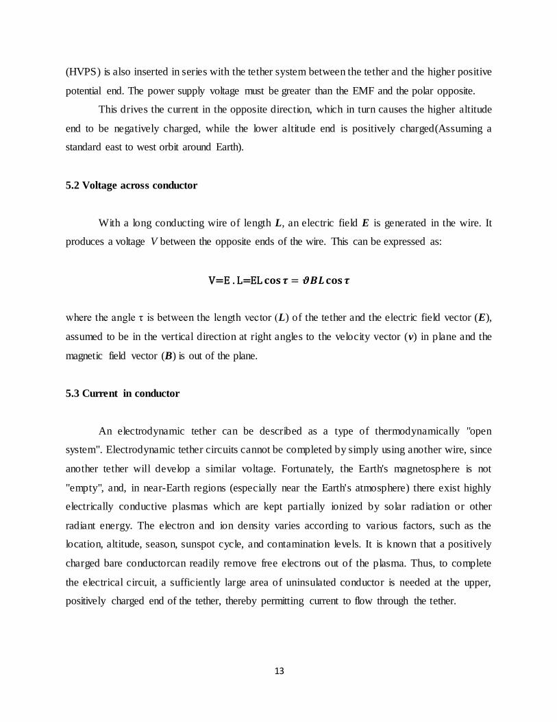
relative to Earth’s magnetic field. Similarly, if current flows in the tether element, a force can be
generated in accordance with the Lorentz Force Equation,
�⃗⃗� = ∫ 𝑰(𝑳)m d�⃗⃗� 𝑳
𝟎
× �⃗⃗�
In self-powered mode (de-orbit mode), this EMF can be used by the tether system to drive
the current through the tether and other electrical loads (e.g. resistors, batteries), emit electrons at the
emitting end, or collect electrons at the opposite. In boost mode, on-board power supplies must
overcome this motional EMF to drive current in the opposite direction, thus creating a force in the
opposite direction, as seen in below figure, and boosting the system.

12
Fig. 5.3 Illustratin of EDT concept
At 300-km altitude, the Earth’s magnetic field, in the north-south direction, is
approximately 0.18 – 0.32 Gauss up to ~40º inclination, and the orbital velocity with respect to
the local plasma is about 7500 m/s. This results in a Vemf range of 35 – 250 V/km along the 5-
km length of tether. This EMF dictates the potential difference across the bare tether which
controls where electrons are collected and / or repelled. Here, the ProSEDS de-boost tether
system is configured to enable electron collection to the positively biased higher altitude section
of the bare tether, and returned to the ionosphere at the lower altitude end. This flow of electrons
through the length of the tether in the presence of the Earth’s magnetic field creates a force that
produces a drag thrust that helps de-orbit the system, as given by the above equation. The boost
mode is similar to the de-orbit mode, except for the fact that a High Voltage Power Supply
13
(HVPS) is also inserted in series with the tether system between the tether and the higher positive
potential end. The power supply voltage must be greater than the EMF and the polar opposite.
This drives the current in the opposite direction, which in turn causes the higher altitude
end to be negatively charged, while the lower altitude end is positively charged(Assuming a
standard east to west orbit around Earth).
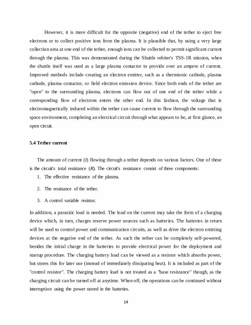
5.2 Voltage across conductor
With a long conducting wire of length L, an electric field E is generated in the wire. It
produces a voltage V between the opposite ends of the wire. This can be expressed as:
V=E . L=EL 𝐜𝐨𝐬 𝝉 = 𝝑𝑩𝑳𝐜𝐨𝐬𝝉
where the angle τ is between the length vector (L) of the tether and the electric field vector (E),
assumed to be in the vertical direction at right angles to the velocity vector (v) in plane and the
magnetic field vector (B) is out of the plane.
5.3 Current in conductor
An electrodynamic tether can be described as a type of thermodynamically "open
system". Electrodynamic tether circuits cannot be completed by simply using another wire, since
another tether will develop a similar voltage. Fortunately, the Earth's magnetosphere is not
"empty", and, in near-Earth regions (especially near the Earth's atmosphere) there exist highly
electrically conductive plasmas which are kept partially ionized by solar radiation or other
radiant energy. The electron and ion density varies according to various factors, such as the
location, altitude, season, sunspot cycle, and contamination levels. It is known that a positively
charged bare conductorcan readily remove free electrons out of the plasma. Thus, to complete
the electrical circuit, a sufficiently large area of uninsulated conductor is needed at the upper,
positively charged end of the tether, thereby permitting current to flow through the tether.
14
However, it is more difficult for the opposite (negative) end of the tether to eject free
electrons or to collect positive ions from the plasma. It is plausible that, by using a very large
collection area at one end of the tether, enough ions can be collected to permit significant current
through the plasma. This was demonstrated during the Shuttle orbiter's TSS-1R mission, when
the shuttle itself was used as a large plasma contactor to provide over an ampere of current.
Improved methods include creating an electron emitter, such as a thermionic cathode, plasma
cathode, plasma contactor, or field electron emission device. Since both ends of the tether are
"open" to the surrounding plasma, electrons can flow out of one end of the tether while a
corresponding flow of electrons enters the other end. In this fashion, the voltage that is
electromagnetically induced within the tether can cause current to flow through the surrounding
space environment, completing an electrical circuit through what appears to be, at first glance, an
open circuit.
5.4 Tether current
The amount of current (I) flowing through a tether depends on various factors. One of these
is the circuit's total resistance (R). The circuit's resistance consist of three components:
1. The effective resistance of the plasma.
2. The resistance of the tether.
3. A control variable resistor.
In addition, a parasitic load is needed. The load on the current may take the form of a charging
device which, in turn, charges reserve power sources such as batter ies. The batteries in return
will be used to control power and communication circuits, as well as drive the electron emitting
devices at the negative end of the tether. As such the tether can be completely self-powered,
besides the initial charge in the batteries to provide electrical power for the deployment and
startup procedure. The charging battery load can be viewed as a resistor which absorbs power,
but stores this for later use (instead of immediately dissipating heat). It is included as part of the
"control resistor". The charging battery load is not treated as a "base resistance" though, as the
charging circuit can be turned off at anytime. When off, the operations can be continued without
interruption using the power stored in the batteries.
15
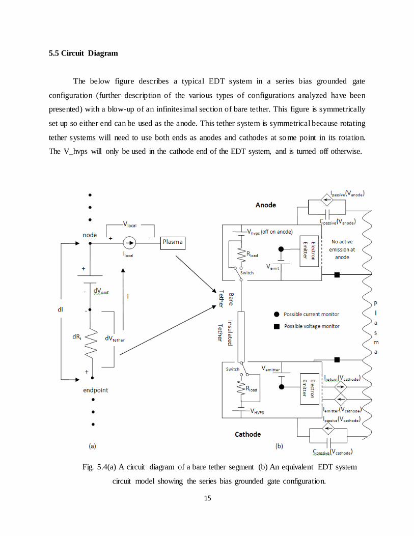
5.5 Circuit Diagram
The below figure describes a typical EDT system in a series bias grounded gate
configuration (further description of the various types of configurations analyzed have been
presented) with a blow-up of an infinitesimal section of bare tether. This figure is symmetrically
set up so either end can be used as the anode. This tether system is symmetrical because rotating
tether systems will need to use both ends as anodes and cathodes at so me point in its rotation.
The V_hvps will only be used in the cathode end of the EDT system, and is turned off otherwise.
Fig. 5.4(a) A circuit diagram of a bare tether segment (b) An equivalent EDT system
circuit model showing the series bias grounded gate configuration.
16
6. TETHER STABILIZATION
Electrodynmic tethers are inherently unstable. The electrodynamic forces also varies and
so this pendulum motion develops in to complex librations in both the in-plane and out-of-plane
direction. The Tether configuration feedback algorithm calculates a gain factor based upon the
network that the electrodynamic forces will perform on the tether dynamics. The second
algorithm requires only periodic measurements of the acceleration of the tether end mass called
End mass acceleration feedback method. These form heart of EDTS provide thermal stability and
efficiency.
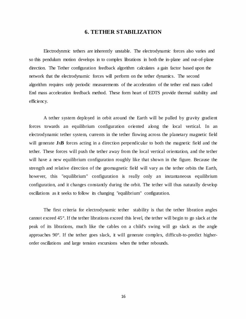
A tether system deployed in orbit around the Earth will be pulled by gravity gradient
forces towards an equilibrium configuration oriented along the local vertical. In an
electrodynamic tether system, currents in the tether flowing across the planetary magnetic field
will generate JxB forces acting in a direction perpendicular to both the magnetic field and the
tether. These forces will push the tether away from the local vertical orientation, and the tether
will have a new equilibrium configuration roughly like that shown in the figure. Because the
strength and relative direction of the geomagnetic field will vary as the tether orbits the Earth,
however, this "equilibrium" configuration is really only an instantaneous equilibrium
configuration, and it changes constantly during the orbit. The tether will thus naturally develop
oscillations as it seeks to follow its changing "equilibrium" configuration.
The first criteria for electrodynamic tether stability is that the tether libration angles
cannot exceed 45°. If the tether librations exceed this level, the tether will begin to go slack at the
peak of its librations, much like the cables on a child's swing will go slack as the angle
approaches 90°. If the tether goes slack, it will generate complex, difficult-to-predict higher-
order oscillations and large tension excursions when the tether rebounds.
17
Fig. 6.1 Drag effects on an Electrodynamic Tether system
6.1 Physics in EDTS :
To calculate the in-plane and out-of-plane directions, the components of the velocity and
magnetic field vectors must be obtained and the force values calculated. The component of the
force in the direction of travel will serve to enhance the orbit raising capabilities, while the out-
of-plane component of thrust will alter the inclination. In the below figure, the magnetic field
vector is solely in the north (or y-axis) direction, and the resulting forces on an orbit, with some
inclination, can be seen. An orbit with no inclination would have all the thrust in the in-plane
direction.
There has been work conducted to stabilize the librations of the tether system to prevent
misalignment of the tether with the gravity gradient. The below figure above displays the drag
effects an EDT system will encounter for a typical orbit. The in-plane angle, α_ip, and out-of-
plane angle, α_op, can be reduced by increasing the endmass of the system, or by employing
feedback technology. Any deviations in the gravity alignment must be understood, and
accounted for in the system design.

18
Fig. 6.2 Description of an in-plane and out-plane force. .
NASA has developed two new feedback algorithms that evaluate the work being
performed on the tether oscillations and calculate a feedback modulation that is applied to the
tether current to achieve net damping of the unstable tether modes. The first algorithm requires
periodic measurements of the location of several points along the tether; this algorithm is
referred to as the “Tether Configuration” feedback method. The second algorithm requires only
periodic measurements of the acceleration of the tether endmass; this algorithm is referred to as
the “Endmass Acceleration” feedback method.
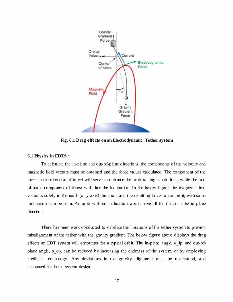
These stabilization algorithms form the heart of the Electrodynamic Tether Stabilization
(EDTS) System, illustrated in Figure, which will enable electrodynamic tethers to provide long-
term propellantless propulsion while maintaining tether stability and efficiency.
19
Fig. 6.3 Electrodynamic Tether Stabilization (EDTS)
20
7. APPLICATIONS
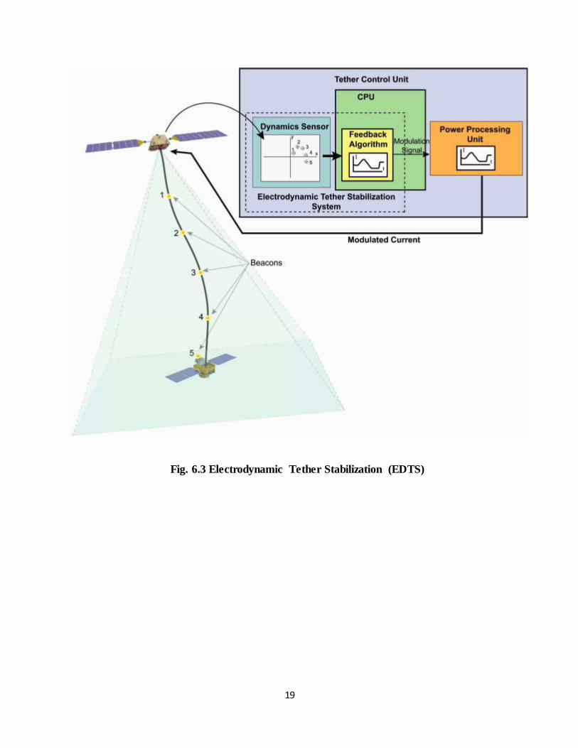
7.1 Propellant less Propulsion for LEO Spacecraft : ED tether system can provide propellant
less propulsion for spacecraft operating in low Earth orbit as shown in fig.8.1
Fig. 8.1
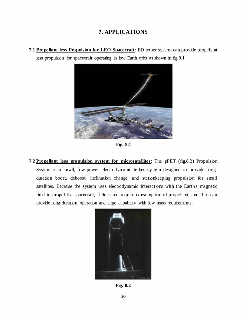
7.2 Propellant less propulsion system for microsatellites: The µPET (fig.8.2) Propulsion
System is a small, low-power electrodynamic tether system designed to provide long-
duration boost, deboost, inclination change, and stationkeeping propulsion for small
satellites. Because the system uses electrodynamic interactions with the Earth's magnetic
field to propel the spacecraft, it does not require consumption of propellant, and thus can
provide long-duration operation and large capability with low mass requirements.
Fig. 8.2
21
7.3 Power Generation in Low Earth Orbit: Electro dynamic tethers may also provide an
economical means of electrical power in orbit.
7.4 Electro Dynamic Revision-Boost of the International Space Station: NASA currently
plans to launch several large rockets every year to carry fuel up to the station so that it can re-
boost its orbit.
7.5 Space Junk Cleanup: The most direct application of ProSEDS(propulsive small expendable
deployer system) would be to get rid of space junk.
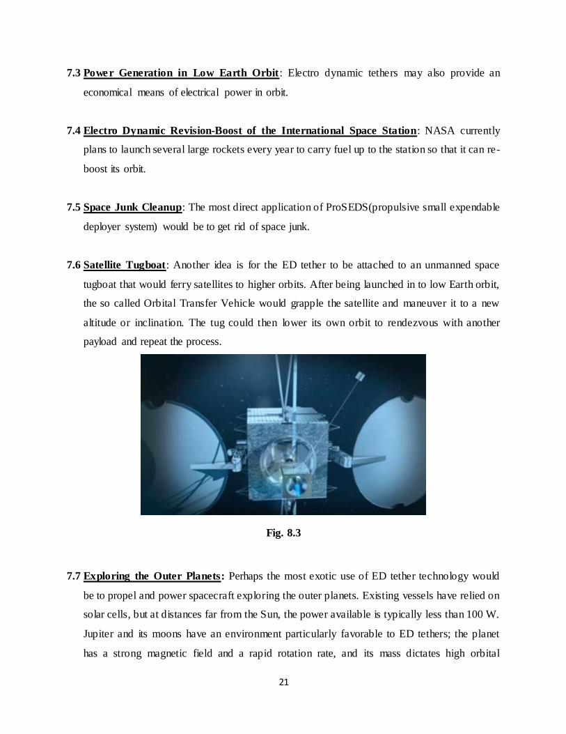
7.6 Satellite Tugboat: Another idea is for the ED tether to be attached to an unmanned space
tugboat that would ferry satellites to higher orbits. After being launched in to low Earth orbit,
the so called Orbital Transfer Vehicle would grapple the satellite and maneuver it to a new
altitude or inclination. The tug could then lower its own orbit to rendezvous with another
payload and repeat the process.
Fig. 8.3
7.7 Exploring the Outer Planets: Perhaps the most exotic use of ED tether technology would
be to propel and power spacecraft exploring the outer planets. Existing vessels have relied on
solar cells, but at distances far from the Sun, the power available is typically less than 100 W.
Jupiter and its moons have an environment particularly favorable to ED tethers; the planet
has a strong magnetic field and a rapid rotation rate, and its mass dictates high orbital
22
velocities. With the magnetic field moving much faster than the spacecraft, the tether would
essentially be stealing energy from the planet's magnetic field.
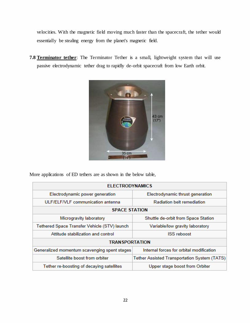
7.8 Terminator tether: The Terminator Tether is a small, lightweight system that will use
passive electrodynamic tether drag to rapidly de-orbit spacecraft from low Earth orbit.
More applications of ED tethers are as shown in the below table,

23
8. BENEFITS OF USING EDTS
1. Saving the Mass: The major advantage of the tether technology compared to other
propulsion systems is that it does not require any propellant. While conventional
chemical thrusters need a mass allocation. A typical electrodynamic tether system,
weighting about 30-50 kg, can achieve de-orbit of spacecraft requiring only a few percent
(1-5%) of the carrier vehicle mass at launch. A tethered system, would be inactive during
the mission, while waiting for a command to de-orbit the spacecraft at the end-of-life.
Therefore, by eliminating the need to launch and store in orbit for many years a large
amount of propellant, electrodynamic tethers can greatly reduce the cost and improve the
reliability of in-space propulsion and operations.
2. Reducing the De-orbit times: Another benefit of using electrodynamic tethers is that the
time to de-orbit spacecraft from LEO can be more. For a typical satellite above 500 km,
affected by the sole natural orbit perturbations, the orbital lifetime can be tens to
thousands of years. On the other hand, the Terminator Tether might de-orbit a satellite
from various LEO orbits within a few weeks to a few months.
3. Increasing the Effectiveness in Terms of the Area-Time-Product: The main objective of a
de-orbit technology is to remove dead and unwanted spacecraft from orbit so that they
cannot pose a collision threat to other operational spacecraft. Of course, the use of a long
tether will greatly increase the cross-sectional area of the spacecraft system, raising, in
turn, the probability that the system will suffer an accidental collision during the mission.
However, this probability depends not only on the cross-sectional area, but also upon the
amount of time the satellite spends in orbit. For a satellite left to de-orbit by aerodynamic
drag only, the cross-sectional area is relatively small, but the amount of time needed to
re-enter the Earth’s atmosphere can be many hundreds or thousands of years.
Nonetheless, even if an electrodynamic tether increases the satellite system cross-
sectional area, the orbital decay rate is large enough to compensate the first effect and to
greatly reduce the risk for the tethered system to collide with other spacecraft.
24
Therefore, the criterion to evaluate the effectiveness of a de-orbit technique is not just
whether it reduces the orbital lifetime compared to the atmospheric drag decay, but whether it
reduces the product of the orbital lifetime and collision cross-sectional area of the spacecraft,
namely the Area-Time-Product: ATP. As a matter of fact, they also demonstra ted that the
Terminator Tether can significantly reduce the ATP value for most LEO orbits.
25
9. RISKS OF USING EDTs
Space Debris Related Concerns: Tethers are usually very long and thin, providing increased
opportunities for something to go wrong. The accidental tether severing may be due to a number
of causes including manufacturing defects, system malfunctions, material degradation,
vibrations, and contact with other spacecraft elements. Most of these causes can be prevented
through design, quality check and active control of the tether dynamics and stability during the
mission.
Nonetheless, due to their peculiar characteristics, tethers in space introduce unusual
problems when viewed from the space debris perspective. They present a much greater risk to
operating satellites due to their considerably large collision cross-sectional area. Because of their
small diameter, tethers of normal design may have a high probability of being severed by
impacts with relatively small meteoroids and orbital debris. The resulting tether fragments may
pose additional risks to operating spacecraft.
Therefore, before electrodynamic tethers can be used to mitigate the problem of orbital debris,
various problems have to be investigated:
1. To evaluate the impact of tethers on the space environment, i.e. to determine the tether
collision risk with operating spacecraft.
2. The risk posed by the tether remnants after severing, the chance of collision among the
tethers themselves.
3. To assess the tether survivability, i.e. to evaluate the risk for a tether of being cut during
the mission by orbital debris and meteoroids.

26
10. FUTURE SCOPE
Satellite Tugboat: Another idea is for the ED tether to be attached to an unmanned space
tugboat that would ferry satellites to higher orbits
Exploring the outer planets: The most exotic use if ED tether technology would be to
propel and power spacecraft exploring the outer planets.
Researchers are investigating the use of ED tethers to extend and enhance future
scientific missions to Jupiter and its moons. In theory, ED tether propulsion could be used near
any planet with a Previous visits to the largest planet in the solar system - including the "Grand
Tour" flyby missions of Voyager 1 and 2, launched in 1977, and an orbital visit by the Galileo
probe, which left Earth in 1989 and it continues to tour and study the Jovian system today- were
illuminating, but the fuel limitations and minimum maneuverability of those probes hampers
long term, more detailed scientific study.
Development of a propellant free, ED tether propulsion system would make it possible to
put a long term probe in Jupiter's orbit - one that could leverage the planet's powerful magnetic
field and magneto sphere to travel freely among the Jovian moons, providing more information
and new insight about them as well. Tether Transport from Low Earth to the Lunar Surface A
concept developed by Tethers Unlimited wherein several rotating tethers in orbit around the
earth and moon may provide a means of exchanging supplies between low Earth orbit facilities
and Lunar bases without requiring the use of propellants.
27
11. CONCLUSION
Electrodynamic tether is now becoming the most popular fuel carrier for spacecrafts. The
use of space tethers is the answer to all the current problems as they don’t require propellents.
ED tethers can provide long-term propellant less propulsion capability for orbital maneuvering
and station keeping of small satellites in low-Earth-orbit. It reduces the de-orbit time unlike other
satellites.
Tether propulsion requires no propellant and is completely reusable. It is also
environmentally clean with low cost. It acts as both booster and braker for a spacecraft. Over the
years, numerous applications for electrodynamic tethers have been identified for potential use in
industry, government, and scientific exploration. Electro dynamic tethers may also provide an
economical means of electrical power in orbit. Beyond these, ETDs are opening new doors in
space explorations and getting close to the universe.

28
12. REFERENCES
Websites:
http://www.tethers.com/
http://www.wikipedia.org/
Books and authors :
1. THE TERMINATOR TETHER - HOYT, R.P., FORWARD, R.L
2. DYNAMICS OF SPACE TETHER SYSTEMS - BELETSKII, V.V.. LEVIN,
3. STABILIZATION OF ELECTRODYNAMIC - HOYT. R.P & HEINEN
4. SPACE TETHERS
5. Columbo, G, et al., Investigation of Electrodynamic Stabilization and Control of Long
Orbiting Tethers, Smithsonian Astrophysical Observatory Interim Report on NASA
Contract NAS8-33691, March 1981.


![Tether anthony[1]](https://img.dokumen.tips/doc/110x75/557c7d36d8b42a494c8b5161/tether-anthony1.jpg)