Embed Size (px)
Citation preview
Design and Testing of a Space Mechanismfor Tether Deployment
Carlo Menon∗
ESA, 2201 AZ Noordwjik, The Netherlands
Michiel Kruijff†
Delta-Utec, 2312 TT Leiden, The Netherlands
and
Antonios Vavouliotis‡
University of Patras, 265 00 Patras, Greece
DOI: 10.2514/1.23454
Amechanism for control of space tether deployment is presented and discussed in this paper. This friction device,
called the “barberpole,”was derived from the textile industry. The mechanism was analyzed, developed, and tested
for the second Young Engineers’ Satellite mission (YES2), which is intended to feature the first European tether
deployment. YES2 further aims to use the tether to accurately deorbit a small innovative reentry capsule. The
barberpole is used for precisely guiding the dynamics of a capsule by controlling the deployment velocity of a tether
that connects the capsule to an orbiting platform, in this case the Foton satellite. Design steps, derivation of a
mathematical model, thermal analysis, and experimental results of the device are presented in this paper. The
exponential dependency of applied friction force vs number of tether wraps around the pole is theoretically and
experimentally proved. Friction performance andpredictability are discussed based on experiments performed both
on ground using a custom-built test rig and during parabolic flight campaigns. The work highlights the suitability of
the barberpole design for space tether applications.
Nomenclature
a = acceleration, m=s2
Cp = specific heat capacity, J=g � �Cd = tether diameter, mFR = centrifugal force, NFz = vertical force, NF� = tangential force, Nf = friction coefficientJp = planetary radiation intensity, W=m2
Js = solar radiation intensity, W=m2
l = pole length, mm = mass, kgN = normal force per unit length, N=mn = number of pole turnsr = pole radius, ms = length tether on pole, mT = tether tension, NTensionin = T tilted over �� with the direction of ds, NTensionout = T � dT tilted first over d� and then over �� d�,
Nv = tether velocity, m=sx0 = dx=dt� = helix angle variable, rad� = linear tether density, kg=m� = turn angle, rad
R0; � = integral from 0 to �
Introduction
T HE Second Young Engineers’ Satellite (YES2) is to performEurope’s first tether deployment to demonstrate a payload
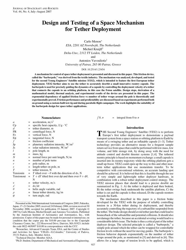
transport system from a space station or orbiting platform to Earth bymeans of a swinging tether and an inflatable capsule [1–3]. Tethertechnology provides an alternative means for a frequent samplereturn service from space that could be performedwith lowmass, lowvolume, and little storage risk, by doing away with the need forattitude control and deorbit thruster systems [1,4]. The tetheredreentry principle is based onmomentum exchange: a small capsule isinserted into its reentry trajectory while the orbiting platform gets asmall up-boost. YES2 could open up the way to this and other near-term tether applications that use momentum transfer. To becompetitive with conventional solutions, an accurate landing spotshould be achieved. It is believed that this is feasible through the useof very simple and lightweight tether deployer hardware, incombination with a robust tether deployment control strategy. TheYES2 mission phases that should lead to a precise deorbit aresummarized in Fig. 1: A) the tether is deployed and then braked,B) the tether swings back underneath the satellite platform, C) thetether is cut and the capsule is thus released, D) the capsule reenterstowards the Earth.
The mechanism described in this paper is a friction brakedeveloped for the YES2 with the purpose of reliably controllingtension in a 30-km tether during its deployment, and therebyaccurately controlling the trajectory of a subsatellite suspended fromthe tether. The brake design should avoid tether jam that could lead tobounceback of the subsatellite and potential collisions. It should alsonot damage the tether, because an accidental severingwould lead to aconsiderable debris issue. The brake is thus a critical part of the tetherdeployer design. The selected principle is called a “barberpole,” asimple pole around which the tether can be wrapped for controllablefriction levels without the need for moving guides. The barberpole’sfriction behavior depends exponentially on the number of tetherwraps around the pole, as mentioned in [5] and derived in [6]. Thisallows for a large range of tension levels to be applied, which is
Presented at the 56th International Astronautical Congress 2005, Fukuoka,Japan, 17–21 October 2005; received 24 February 2006; revision received 30November 2006; accepted for publication 19 January 2007. Copyright ©2007 by Carlo Menon, Michiel Kruijff, and Antonios Vavouliotis. Publishedby the American Institute of Aeronautics and Astronautics, Inc., withpermission. Copies of this paper may be made for personal or internal use, oncondition that the copier pay the $10.00 per-copy fee to the CopyrightClearance Center, Inc., 222 Rosewood Drive, Danvers, MA 01923; includethe code 0022-4650/07 $10.00 in correspondence with the CCC.
∗Researcher, Advanced Concepts Team, ESA, and the Center of Studiesand Activities for Space “CISAS—G.Colombo,” University of Padova,35131 Padova, Italy. Member AIAA.
†Technical Director. Member AIAA.‡Ph.D. Student, Department ofMechanical and Aeronautical Engineering.
JOURNAL OF SPACECRAFT AND ROCKETS
Vol. 44, No. 4, July–August 2007
927
required for proper control at very short (300 m) and very long(30 km) tether lengths under associated gravity-gradient forces. Thispaper seeks to determine the limits of applicability of such simplemodels both by analysis and test, and to increase the understanding ofthe brake’s friction performance under the various circumstances thatmay be encountered in the space environment. The aim of this paperis furthermore to document the mechanical design tradeoffs forYES2’s implementation of this concept.
The barberpole has been designed taking advantage of theexperience and know-how of the textile industry [7]. Friction brakeshave been used in the textile industry to introduce a constant tensionlevel in yarns or fibers. There are no open or moving guides and theyarn is not compressed or damaged by the braking mechanism. Firstsuccesses of tether brakes using this principle in space were theSEDS1 and SEDS2 (small expendable deployer system) missions[8–10]. In these missions, 20 km of tether were deployed. A thirdSEDS brake system was included on ESA’s YES1, the first satelliteto feature a failsafe multistrand tether. This record-breaking 35-kmtether [11] was, however, not deployed, due to safety issues [12]. InEurope, the SEDS system was used as an example for the controlsystem in the “Tether System Experiment” (TSE) project [13]. TheTSE and SEDS brakes have a relatively small sleek pole compared tothe design in this paper. The motor that drives the gear is fixeddirectly to the housing, such that a highly precise alignment isrequired to allow for proper operation. One of the reasons to use astepper motor is that the motor can be driven in open loop; there is noencoder. Tests were performed for TSE, but the project waseventually canceled. In one high-speed/high-tension test, the tethermelted. Then, after the YES1 and TSE projects, it was found thatreliability, thermal performance, performance predictability, androbustness could not be properly demonstrated for the earlier designsand it was therefore obligatory to develop and qualify from scratch anew barberpole brake system for the European Space Agency. Theinnovative value of the new European system described in this paperlies in the increased understanding and optimization of the concept’sperformance as a result of design tradeoffs, analysis, and testsperformed. The YES2 mission explicitly requires a strict tetherdeployment control and a high level of safety. A better mathematical
understanding was required to help understand under whichconditions performance would be maintained. The mathematicalmodel has led to a new dimensioning of the pole, with more uniformperformance, as well as reduced entry guide distance to the pole formore efficient use of the increased dimension, and finally a curvaturein the pole surface that is intended to help stabilize the tether motionon the pole. Surface treatment effects were studied to come to a clearmanufacturing procedure. In addition,when the deploying tether is incontact with the barberpole and subjected to high friction in vacuum,the tether can easily melt, causing the failure of the mission. The newdesign is therefore for a significant part driven by increased thermaldissipation. An extra guide and reliaflex coupling were added to thebrake system to decrease misalignment torques. Systematic analysesand tests of the braking mechanism were carried out.
In the first part of this paper, the main requirements for andcharacteristics of the barberpole are presented and a mathematicalmodel is described. Possible solutions for barberpole configurationsare shown and pros and cons of each configuration are discussed. Athermal analysis is then presented to verify that the tether will notmelt during the deployment phase. A barberpole breadboard wasdeveloped and the experiments performed with it are discussed. Thepaper ends with a conclusion on the understanding of theperformance and the suitability of the tested barberpole for YES2.
Problem Definition
The objective of the YES2 mission is to demonstrate a safe andprecise capsule reentry using tether technology. To be an interestingcost-effective alternative to conventional solutions, the systemshould be compact and reliable. Therefore, we strive for subsystemsthat are simple, well-tested, and with few interfaces. Awareness ofrisks and contingencies is a key point for the success of the mission;failures and abort options must be identified and evaluated. Inparticular, the barberpole should be lightweight and easy tomanufacture. Performance should be predictable and replicable, andvariations in parameters should be able to be compensated for viafeedback. It should be effective in a wide range of tension levels, soan exponential performance is preferred. For reliability and safety itshould have few moving parts and few tether guides. The designshould effectively conduct heat away from the friction surface.Performance should be understood and demonstrated in allforeseeable circumstances.
These requirements led to the selection of a barberpole concept.Figure 2 shows a tether wound four times around a pole. The tensionof the tether increases approximately three times for each turn of thetether around the pole, as will be shown in the next section. At theentrance hole of the braking tether pole, the tension is about 10mN. Itis nonzero because the tether must first be unwound and acceleratefrom a storage spool inside a box (canister).
Therefore, four turns around the brake introduce a tether tension atthe exit hole (see Fig. 2) of almost 1 N. The dynamic of the spacemission requires a tether tension from 10mN (no turns) to 3N (aboutfour turns). The difficult characterization of the tether dynamicsduring braking operations has required the development of a robustdeployment control algorithm and the construction of a real-timetether deployment test rig, which was developed at the University ofApplied Sciences Koblenz in Remagen (Germany).
In Fig. 2, the entrance and exit holes are fixed to the pole, thuspreventing control of the tether deployment speed. It is thereforenecessary to develop a more sophisticated mechanism that is able tochange the number of turns around the pole to brake the tether in aneffective way. The mechanismmust also keep down the temperatureof the tether to prevent its breakage. The tether foreseen for YES2mission is a polyethylene wire, Dyneema, selected for its lowdensity, high strength and stiffness, and smooth flexible surface. Thecharacteristics of this material are shown in Table 1. Stiffness ishighly dependent on usage, tension history, and load and as a resultcan easily vary by a factor of 10 from one application to the next [13].Because of the low tension levels and high material strength, thediameter of the tether is determined by the meteorite cutting risk, andwas fixed at 0.5 mm.
Fig. 1 Four mission phases. A: tether is deployed, B: tether swings
back, C: tether is cut, and D: the capsule reenters.
928 MENON, KRUIJFF, AND VAVOULIOTIS

Mathematical Model
As mentioned, the exponential dependency of applied frictionforce vs number of tether wraps, or “turns,” around the pole isbeneficial for control. In the required large range of deploymenttension, such a model would allow for a simple linear controlalgorithm.Byusing themathematicalmodel described in this chapterand performing experiments on different kind of barberpoles, thedeviation from a pure exponential dependency between friction forceand pole turns was assessed.
The mathematical model of the barberpole braking performance(see Appendix for details) was based on several importantassumptions. In particular, the velocity v of the tether around the poleis assumed constant, the tether density � is constant, the tether entryand exit points arefixed and located on the extremities of the pole, theincoming and outgoing angles of the tether can change, the poleradius r is constant, and the tether has no bending stiffness.
The first conclusion, which is drawn from themathematical modelunder the aforementioned assumptions, is that the tether shouldassume the shape of a helix (� is constant). Hence, the helix angle �can be calculated from the number of turns and geometry of the pole:
tan �� 1=2�nR (1)
The length of the piece of moving tether instantaneously in contactwith the pole equals
s� l= sin � (2)
Another important conclusion is that the tether should stay in contactwith the pole if the normal force remains positive. This statement istrue if and only if the incoming tension T meets the conditionT > �v2. This condition is intuitively understood as the inertia of thetether has to be overcome.
The term �v2 is known as the “rocket term” [14]. This term equalsthe tension that will occur in a tether due to the energy shock (Carnot)that it experiences whenmaking the transition from being stored on afixed spool to deploying at constant velocity. Because YES2 willhave such a spool, the tether tension will include a rocket term. Thetension at the entrance of the barberpole will be an amplified versionof this term, due to bending around guidance surfaces and frictionforces encountered along the way.
Therefore, the condition T > �v2 is always met and implies that anonstiff tether deployed from a spool at constant velocity will be incontact with the barberpole brake regardless of density ordeployment speed. This conclusion does not hold for stiff tethers(required bendingmoments will set a tougher condition to meet), nornecessarily for decelerating deployment (inertia effects of tether atthe low friction end). Strongly decelerating deployment in a typicaldeployment is initiated by the barberpole friction itself rather than byreduced gravity gradient (or sudden stop of a test-rig reelingmechanism), so probably deceleration will not give any problems forthe tether/pole contact.
The third conclusion from the mathematical model is that thetension in the tether as it leaves the barberpole is nearly proportionalto incoming tension and depends nearly exponentially on the turnangle � and friction coefficient f, according to
T � �T0 � �v2�ecos �Rf d� � �v2 (3)
This equation has interesting implications for the system physics.Notice that this formula contains the rocket term, even though shockaccelerationswere not part of themodel. It predicts, however, that therocket term passes the brake unamplified. For constant frictioncoefficient f the formula simplifies to
T � �T0 � �v2�e2�fn cos � � �v2 (4)
Or, expressed in geometrical design parameters,
T � �T0 � �v2�e2�fn������������������������������������������1=f1��1=2�n=�r�0:5d�2g�p
� �v2 (5)
Figure 3 shows the predicted performance [Eq. (4)] relative to anidealized exponential barberpole (T � T0e2�fn). Plots are for threedifferent friction coefficients: f� 0:1, 0.18, and 0.3. The verticalaxis is relative performance (1� idealized exponential), with stepsof 5%. Horizontal (back-to-front): number of brake turns, with stepsof 0.25 turn. The lower axis extreme of 1 corresponds to zero turns,the upper value of 21 corresponds to five turns. Horizontal (left-to-right) is pole ratio (radius/length), where s1 corresponds to a ratio of0, and s11 to 0.25; steps of 2.5%. Behavior relative to a simpleexponential also depends on the friction coefficient. A relativelythicker pole is better and a lower friction coefficient more closelyapproaches the ideal result (no relative losses due to helix angle).Losses are largest at one turn: 40%. For higher frictioncoefficients, the effect is more pronounced. For poles with adiameter > 0:25 length (curves on back wall), performance isgenerally better than 80%, so a simple exponential fit will suffice.Thinner poles, however, have heavily degraded performance (left-side curves).
Fig. 2 Canister and braking tether pole.
Table 1 Dyneema characteristics
Physical properties Fiber YES2 tether
Density 970 kg=m3 915 kg=m3
Tensile strength, ultimate 3500 MPa 500–1500 MpaModulus of elasticity 110 Gpa 25 GPaOnset of performance degradation 70�C 70�CMaximum usage 120�C 120�CMelting temperature 150�C 150�C
MENON, KRUIJFF, AND VAVOULIOTIS 929

Barberpole Design
With the required exponential behavior established for thebarberpole concept, several configurations have been designed toobtain a high-performance barberpole. In this section, the mostpromising solutions are presented. Figure 4 shows the firstconfiguration of barberpole, which is made up of three maincomponents: one motor, one pole, and one external cover. Thisconfiguration can be very compact and reliable because only a fewcomponents are used. The motor turns the pole around its axis andwinds the wire. To have a position of the mechanism in which thetether is allowed to move freely through the barberpole withoutactually touching it (zero friction), the entrance and exit holes arealigned. This constraint implies a complicated path for the windingtether (see Fig. 4) and complicates the dynamic model of the system
and the speed control of the tether. A torque is applied continuouslyby the tether directly on the motor, increasing system requirements.A second configuration is shown in Fig. 5. In this case, the exit hole isfixed to the end of the rotating pole and the tether winding path ismore regular.
There are two inherent drawbacks for these two barberpoleconfigurations. The first one is related to the mechanical rigidity. Forboth configurations, the pole is turned by the motor around its axis.Therefore, the pole behaves as a cantilever. A bearing system musttherefore be employed to increase themechanism stiffness necessaryto withstand both the launch phase (random, quasi-static, andsinusoidal excitations) and the operational phase of the mission. Thesecond drawback concerns the barberpole thermal behavior. Inspace, conduction and irradiation are the only two ways oftransferring heat energy. In the aforementioned configurations, thepole must rotate to allow control of the tether speed. The use ofbearings or other sliding systems is therefore needed. The totalconduction of the barberpole is thus compromised and the possibilityof melting the tether increased.
Other configurations were examined. Figures 6 and 7 show twobarberpole geometries characterized by nonrotating poles. Thetension and therefore the torque at entry is much smaller than at exit,so the entrance could easily be moved directly. The exit mustpreferably open into (free) space. In Fig. 6, the position of the tetherentrance hole is controlled by a motor through a shaft. In Fig. 7, themotor directly guides a beam and the position of the tether entrancehole. By having a fixed pole, the thermal performance of thesebraking mechanisms is improved.When the barberpole is joined to amassive thermal sink, as in the YES2 mission, the heat produced bythe friction between tether and pole can easily be dissipated.However, despite the notable advantages of these two configura-tions, their use was prevented by the YES2 mission constraints.
The first constraint was related to the small space available for thebrakingmechanism limiting its dimensions. The second constraint isthe barberpole diameter. In fact, it must be noted that the entrancehole has a circular trajectory around the axis of the pole. A smaller
Fig. 3 Predicted friction performance [Eq. (4)].
Fig. 4 First barberpole configuration.
Fig. 5 Second barberpole configuration.
930 MENON, KRUIJFF, AND VAVOULIOTIS

pole diameter is therefore preferred because it assures small positionchanges of the entrance hole with respect to the canister tether exit.
The final barberpole design for the breadboard model is shown inFig. 8. This design, which is based on YES1’s SEDS deployermechanism concept, is made up of a pole that is fixed to an externalcasing. The entrance hole is set on a tooth wheel, which is controlledby a motor that rotates a shaft and a worm gear.
The main differences with respect to the SEDS system are gearratio (reducing required motor torque), motor fixture (increasingfriction but allowing formisalignments), pole base design (large basefor increased thermal conductivity and heat capacity), and poledimensions and shape (based on model results and testrecommendations). A second worm to reduce the tooth wheel’sfreedom during launch was considered, but rejected as overdesign.
The main advantages of this configuration over the other conceptsare manifold. In particular, the pole, ground plate, and guide are asingle integrated piece. In addition, the barberpole is fixed to a frame(heat sink), which benefits thermal dissipation. This configurationhas also a space-saving geometry. For this configuration atransmission mating mechanism is used for torque reduction, which
allows using a low power motor. The nonreversible worm/tooth-wheel transmissionmatingmechanism keeps the free rotations of themechanism steady during the launch phase while no current isprovided to the payload. Misalignments are compensated by using aflexible motor–axis connection
The technical characteristics of thisfinal barberpole are as follows:Vespel, a low-friction polyimide, is used for the entrance guide. Theexit guide ismilled directly into the aluminum frame, for optimal heattransfer. Sliding bushes are employed at the rotating interfaces toreduce friction and present low failure probability. A steppermotor ispreferred for its deterministic nature, allowing for open-loopsoftware control. A space-qualifiedmotor (Phytron VSS 32.200.1.2)is planned.
Theworm/tooth-wheel mating, which is used to amplify themotortorque, has a reduction ratio equal to 120. An 8 kHz half-step modeallows winding of the tether around the pole once every 6 s, which isin accordance with mission requirements. Half-step mode leads todouble frequency and extra power and torque loss, and is mainlyselected to reduce vibration resonance losses within the motor.
Figure 8 also shows the tether-cutter mechanism. This barberpolesubmechanism is aimed at cutting the tether at the end of thedeployment phase. It is made up of a holder and two redundant pyro-cutters (Cypres AirTec).
Thermal Analysis
Introduction
The presented design was heavily influenced by thermalconsiderations, because melting of the Dyneema by friction heatingwas considered a serious risk. To evaluate the thermal behavior of thedesigned barberpole during the YES2 mission, a thermal analysiswas performed using ThermXL provided by ALSTOM Co. Forgeneral applicability of this work, the barberpole assembly isassumed to be independent, not taking into consideration anymechanical or thermal interfaces with other YES2 subsystems. Thisassumption is conservative for the specific scenario of the YES2mission as the hot case is of concern and the conductive interfaceswith other subsystems will lead to additional cooling. The analysisperformed takes into account the thermal environment of the lowEarth orbit of FOTON [15] and also the tether deployment profile ofthe mission [16].
Modeling
A CAD design is used for the thermal analyses. The barberpoleassembly is represented as a six-sided box with the stepper motorfixed on one side of the box. Inside the box there is the pole (cylinderand flange).
The entire assembly is modeled with 13 nodes (see Fig. 9 andTable 2). The parts that aremodeled are the housing, the pole, and themotor. Every node is assumed to be in perfect contact with theadjoining nodes as if they were all from one part. Every external sideof the box is an isothermal area, so every side of the box is a discretenode.
Fig. 6 Third barberpole configuration.
Fig. 7 Fourth barberpole configuration.
Fig. 8 Latest barberpole configurations. The first picture is the testing breadboard, which allows for easy testing of a variety of parameters. The second
represents the flight design.
MENON, KRUIJFF, AND VAVOULIOTIS 931

Space Environment
Weassume theworst scenario inwhich one side of the box absorbsradiation directly from the sun and a second (the top of the box)receives albedo and infrared from the Earth (see Fig. 10 and Table 3).Values concerning radiation heat input are calculated assuming thatthe satellite passes from full sun exposure to full eclipse (orspacecraft shadow) every 45min (2700 s). In the worst-case scenariothat is considered, the heat output is primarily considered to becoming from three sides of the assembly that are radiating to deepspace. The conservative analysis performed does not consider theheat transfer between Foton/YES2 and the barberpole assembly.
The panel that receives the sunlight, the onewith the steppermotorattached, is assumed to dissipate 5 W continuously. The heat input(dissipated power) given by the friction of the tether on the pole’ssurface is calculated by multiplying the tether’s tension force by thetether’s velocity. This product reaches a peak power of tens ofWattsduring the final minutes of deceleration. It is conservatively assumedthat half of this heat input passes to the pole and the other half isequally distributed along the deployed length of the tether. Thisassumption is conservative because the tether is cooler than the pole,as it does not accumulate heat in passing. The dissipated power isdistributed over the nodes of the pole according to Eq. (3), whichwilllead to input mostly into the tether exit in the pole base (node 1),which is bolted to the box (node 7). Values of the parameters areselected in a way to define a worst-case heating scenario so that theycan give an indication of the robustness of the design.
The analysis performed is a transient one [17]. The analysiscalculates the temperatures of the YES2 satellite for 20,800 s(covering startup and full deployment). The initial temperature is0�C. The cyclic trends in the results are due to the eclipse thatoccurs every 90 min.
Thermal Analysis Results
The temperature changes are governed by the extremes of theorbital environmental circumstances. It can be seen (Fig. 11) that the
peak value occurs when the maximum tension on the pole is appliedduring the deceleration phase (Fig. 1) of the capsule (decelerationfrom 12 m=s to zero in fewminutes). A rise of about 50 deg is causedby the braking action (as seen from increase in peak level). Thehousing also gets quite hot. The temperatures are within theacceptable range, even if the initial temperature will be lower in thereal scenario. No conduction to the YES2 is assumed. The thermalperformance of the pole itself (minimizing the influence of frictionheat) can be further improved by applying thermal paste and boltingit tightly to the barberpole housing.
Breadboard for Experimental Tests
With the design completed and initial confidence obtained byanalysis, a barberpole breadboard was built for experimental testsincluding friction and contact behavior, performance in zero-g and
Fig. 9 Barberpole configuration and nodal breakdown.
Fig. 10 Heat input/output.
Fig. 11 Barberpole temperature estimation. Temperature within the
pole itself varies less than 5�C.
932 MENON, KRUIJFF, AND VAVOULIOTIS

vacuum, and finally performance in a closed-loop control. Figure 12shows the tether-cutter subsystem and the overall barberpole system.In Fig. 12, the tether goes through the entrance hole of the toothwheel, turns six times around the pole and goes through the tether-cutter subsystem. The tether winds with a regular path around thebarberpole as predicted in the mathematical analysis.
However, during preliminary tests, performed by means of a test-rig facility (discussed in the next section) that was especiallydeveloped for ground tests [7,18,19], the predicted helix shape wascompromised, as the tether loops under some circumstances tendedto collect near the entrance (compare Figs. 13a and 13b). In principle,this shape deviation is not an issue as the helix angle decreases formost turns and the braking effectiveness increases (the total contactlength of tether with pole increases). However, in extreme cases,tether loops could overlap and, as a net result, friction output could bereduced significantly with respect to the exponential model. It wouldbe evenworse if some entanglementwith tether or gearwere to occur.
It seems that tether loops mostly overlap at a high number of turns(>2:5), on narrow poles with low surface roughness, with lowincoming tension and thick tethers. Simple tests indicate that velocityand temperature seem not to be involved in the cause of the undesiredeffect. Amethodological sequence of tests revealed that the observedbehavior is the result of a combination of four contributions that wedefine as 1) internal torque (result of the braiding), 2) twist,3) wrapping direction around the pole (it determines the direction ofthe previous effect), 4) pole tendency (a certain natural tendency ofthe pole, which is not yet understood but seems unaffected by any ofthe aforementioned parameters). We were able to qualitatively but
consistently define the relation between the separate effects asfollows:
Net torque effect on helix � �twist� internal torque�� wrap direction� pole tendency (6)
To identify the best diameter or surface treatment to match themodels, several poles with different shapes and roughness were builtand tested. The characteristics of the poles are summarized inTable 4. Surface roughness was determined using a MitutoyoSurftest SV-3000. The measurements vary from ranges of 5–20 �mto ranges of 0:5–2:5 �m. The sandblasted poles were found to weardown during deployment tests, so a hard or anodized coating isadvised.
One pole was manufactured that does not have a cylindrical shapebut is tapered with a curve: it has a 24.2 mm diameter at the entrancehole and a 23 mm diameter near the exit hole. The section of the polefollows an arc profile with a 4 m radius as sketched in Fig. 14. Thisgeometrywas chosen to avoid the described collection of tether at theentrance hole,without driving the loops to the exit hole. The resultingsemicone angle at entrance is 1 deg, an angle that is based on roughpreliminary tests that show that the axial force component induced bythis angle is sufficient to drive the loops towards the narrower end ofthe pole. The exit side of the pole is cylindrical (0 deg). A polishedaluminum surface led to a perceived too-low friction coefficient, sothe curved pole was tested with two different surface treatments.
Fig. 12 Left: tether cutter. Right: barberpole (including pole “curved 1”).
Fig. 13 Path of the tether around the sandblasted and smooth-surface wide diameter poles.
MENON, KRUIJFF, AND VAVOULIOTIS 933

Tests and Results
Friction Performance and Predictability
Ground tests were carried out using a custom-built facility, the testrig. Its main task was to pull the tether from the canister through thebarberpole at the velocity that an ejected and separating capsule in thespace environment would have. The main components of the test rigare shown in Fig. 15. Starting from the left of Fig. 15, the first twocomponents are the satellite: tether canister (from which a tetherdeploys axially) and the barberpole. The third device is atensiometer, which is able to measure the tension of the tether thatexits the barberpole. This tension is a result of the barberpole’sinduced friction and is stored as data, but can also be sent to a real-time simulator that uses it inside a force balance in a simulated spaceenvironment. The fourth device is the galet, which is a motorizedmechanism able to pull out the tether from the spool inside thecanister, which is driven by the operator directly or by the real-timespace simulator. The remaining components are buffers and sensorscooperating to recover the tether for reuse [12].
The ground experimental testbed thus allowed performance ofextensive tests to verify both the control law and the barberpoleperformance. In this section the results concerning barberpoleperformance are shown and discussed.
During tests, the poles of Table 4 were mounted, in turn, on thebarberpole. For each test, a fixed number of tether turns around thepole was used at a constant speed (1 m=s) and 1 km of tether, woundon a 70-mm-diam spool core, was employed. Each pole was tested inthe range of 0–3.5 turns. The increment for successive experimentswas 0.25 turns. Tether tension datawere recordedwith a frequency of1 ms. Previous experience [12] has shown that the one-sigma noisearound the tension averages at each number of turns amounts to about30–40%.
Table 2 Geometrical and material data used
Housing Pole Stepper motor
Number of nodes 6 Number of nodes 6 Number of nodes 1
Geometrical data, m
Length of each primary side 0.1 Length of the pole 0.07 Length 0.032Width of each primary side 0.1 Thickness flange 0.005 Width 0.032Thickness of each primary side 0.003 Diameter of the pole 0.024 Thickness 0.039Length of each secondary side 0.1 Diameter of the flange 0.07 Diameter 0.032Thickness of each secondary side 0.0005 —— —— —— ——
Material data (Aluminium used)
Thermal conductivity 209 W=mK Thermal conductivity 209 W=mK Thermal conductivity 209 W=mKThermal conductivity between plates 200 W=m2K Thermal conductivity
between plates200 W=m2K Thermal conductivity
between plates200 W=m2K
Density 2700 kg=m3 Density 2700 kg=m3 Density 2700 kg=m3
Cp heat capacity (J=g � �C) 0.9 Cp (J=g � �C) 0.9 Cp (J=g � �C) 0.9Absorptance (internal surface) 0.9 a 0.15 a 0.9Emittance (internal surface) 0.9 e 0.9 e 0.9Absorptance (external surface) 0.15 —— —— —— ——
Emittance (external surface) 0.9 —— —— —— ——
Table 3 Selected values for solar (Js) and planetary (Jp) radiationintensity
Value Unit
Js 1371 W=m2
Jp (240 km orbit) 220 W=m2
Table 4 Pole characteristics. Coating index: 1� polished aluminium,
2� hard anodized, 3� hard coated,
4� sandblasted-hard anodized-polished, 5� sandblasted.
Friction coefficient: see Sec.
Pole Friction Roughness, �m Diameter, mm Coating
1 0.15 0.57 24 32 0.24 0.76 17 33 0.18 0.64 13 34 0.18 0.59 17 15 —— 0.75 13 16 —— 0.7 24 47 0.34 1.74 24 58 0.28 1.92 17 59 0.3 2.26 13 5Curved 1 0.21 —— 24 2Curved 2 0.25 2.7 24 4
Fig. 14 Sketch of the section of the curved pole (exaggerated graphics
of curvature). Fig. 15 Barberpole test rig.
934 MENON, KRUIJFF, AND VAVOULIOTIS

Exponential fits are added to the data, from which the frictioncoefficient is estimated: the exponential coefficient of the tensioncurve divided by 2� [simplification of Eq. (3)]. Figure 16 showsresults of the average tension of the tether for the three sandblastedpoles. Especially for the sandblasted pole there seems to be a cleartrend of increasing friction performance with pole diameter.According to the mathematical model, this effect would not so muchbe a true friction effect; rather it is improved tension amplification.Figure 17 shows experimental results concerning the two coated bigpoles, which differ mostly in shape (cylindrical vs curved). Thecurved pole seems to maintain its purely exponential behavior thelongest, which is probably related to the fact that the cylindrical polehad an early onset of instability of the helix pattern (observedvibration of coils from about 2.5 turns). Figure 18 compares theexponentials for different surface treatments, and the sandblastedpole clearly stands out.
In general, the exponential shape is well followed until aboutn� 3 or 3.5. After that level, generally some relative losses intension can be observed (except perhaps for the curved pole).
In Fig. 19, a trend between roughness and friction coefficient canbe observed, which was found to be the main effect. Also thetreatment can be found to have some influence (Fig. 20) althoughmostly for the sandblasted poles (Fig. 18). The various tests indicate apredictability of friction coefficient of about�20%, which should betaken into account in mission simulations.
Visual Observations
Figures 13a and 13b, respectively, show the path of the tetheraround the sandblasted and smooth-surface wide diameter poles.Whereas in Fig. 13a the tether winds around the pole with a quasi-perfect helicoid, in Fig. 13b the tether is gathered near the toothwheel.
Visual observations consistently indicate that the homogeneityand regularity of tether winding around the pole can be maintained
for very large numbers of turns ( 5) by selecting the appropriatefriction coefficient (>0:25), and/or by applying a mild curvature.However, having a too high friction coefficient or too high curvaturecan even lead to collection of loops on the exit side of the pole. Thecurvature leading to an entrance cone angle of 1 deg is (just) slightlytoo much.
Onset of instability was found to be directly associatedwith loss ofperformance. Its causes are as yet unclear, but its eventual solution isexpected to extend the exponential performance to a larger number ofturns. The sensitivity of the pole shape to tether twist indicates thatseemingly small effects could be at the root of this remainingproblem. Apart from the helix shape, tether irregularities, stiffnesscombined with localized twisting, and noise in incoming tension orin velocity are some directions for further study. As for now, in ourfurther development of the deployment system we are trying tominimize all these potential causes. Then, especially with the hard-coated poles, it was observed that thinner poles seem to postpone theonset of instability, most likely because of the larger helix angle,
Fig. 16 Average tension of the tether for the three sandblasted poles,
precision better than 0.1 N.
Fig. 17 Average tension of the tether for the coated big poles
(cylindrical vs curved), precision better than 0.1 N.
Fig. 18 Average tension of the tether for the middle diameter poles,
precision better than 0.1 N.
0.15
0.2
0.25
0.3
0.35
0 0.5 1 1.5 2 2.5 3
Roughness [um]
Fric
tion
coef
ficie
nt [-
]
Fig. 19 Trend between roughness and friction coefficient.
0 .1
0 .1 5
0 .2
0 .2 5
0 .3
0 .3 5
1 2 3 4 5S u r f a c e t r e a tm e n t
Fric
tion
coef
[-]
Fig. 20 Influence of the surface treatment on the friction coefficient ofthe poles. See Table 4 for surface treatment index.
MENON, KRUIJFF, AND VAVOULIOTIS 935

which makes them better than the bigger diameters. Somehow thecoatingmay have some stabilizing influence compared to the smoothpoles (Fig. 18).
Design Recommendations
It has been concluded that a surface roughness of 1–2:5 �m isrequired, because a polished surface has low friction coefficient,associated poor helix shape, and early onset of instability. A coating,preferably hard anodization, is required to avoid wear of the surface.A large pole length relative to tether diameter can be expected toreduce the risk of tether overlap. A larger pole diameter bothexperimentally and mathematically predicts better tensionamplification performance. Thermally, a large pole heats up less.Some curvature can be introduced to avoid collection of the tether onthe incoming side (also reducing risk of overlaps), delayingsomewhat the onset of instability, but too much curvature couldpossibly cause collection on the exit side as well as instability.
The best performance is thus expected from the curved, hardanodized, large pole.
Barberpole’s Performance in Extreme Cases
The barberpole-delivered tension was measured up to 25 N, evenwith very low incoming tension. Although the exponential model didnot hold as well above five turns, the barberpole could applysufficiently predictable tension up to 25 N, and most likely beyond(Fig. 21).
At very low velocities, the friction coefficient seemed to drop. Thecoefficient was found to be very low (fn � 0:12 rather than the usual0.25) at low speed (5 cm=s), but such results have to be interpretedcarefully due to the possibility that tensiometers do not behaveoptimally at such low speeds. Furthermore, the tether deploymentdrive (galet) does not deliver a constant/smooth velocity in this verylow region. Such speeds effectively only occur at the end of the firststage deployment of YES2 (3 km), at which time a higher gain levelis recommended for the software controller to account for it.
Performance in Vacuum
A drop-weight setup was built in a vacuum chamber (SSAU,Samara, Russia) as in Fig. 22. Vacuum level was about 5.10–2 mmHg. The tether is draped over suspended metal rods to obtain asafe distance from the pole box, and allow for smooth sliding, thuscreating the possibility to test the pole in horizontal configuration asdisplayed. Known weights are attached to each side, 2 and 20 g, thelarger weight on the outgoing side. It is expected that the minimumtension amplification factor of 10 (20=2) required to keep the massfrom dropping can be achieved by two turns. The pole is driven(turned) by a controller setup outside the vacuum chamber. There isan observation window on either side. The drop height that can bewitnessed is about 40 cm and typically takes10 s with the pole incritical setting (friction in balance with weight; minimal, smoothvelocity).
The test was performed six times in air and four times in vacuum(Fig. 23). The results show virtually the same friction coefficient inthe two cases (0:26� 20% ambient vs 0:24� 33% vacuum). Ifeither of the extremes of measured friction coefficients was to occur
as an average during a controlled deployment (in test or in space), acontroller correction of 0.2 turns (ambient) or 0.4 turns (vacuum)would suffice to recover. These numbers seem valuable to take intoaccount for mission safety/robustness simulations.
The vacuum measurements are noisier and the videos of the dropmotion of the vacuum cases seemed much less uniform, suggestingthat in vacuum at low speeds, stick-slip processes may be lessreproducible.
Microgravity Environment
To verify correct deployment performance (unwinding of tether,entry of barber pole, and brake performance) in weightlessness, aparabolic flight experiment was performed by a YES2 student teamas part of ESA’s Fifth Student Parabolic Flight Campaign. Themicrogravity environment was obtained through two series of 30parabolic manoeuvres of a modified aircraft (Airbus A300 Zero-G).Each parabola was characterized by three main phases. Twentyseconds of 1.8 g (“pull up”) is followed by the microgravity phase,also roughly 20 s, with an acceleration of �5 � 10�2 g for thevertical axis (z axis) and�10�2 g along the x and y directions. Afterthe microgravity phase, a 20-s vertical acceleration is reached oncemore, 1.8 g (“pull down”).
TheYES2 tether deployment test rig was specially prepared, and avacuum cleaner replaced the tether recovery system to dispose of thedeployed tether. The rig was run at 1 m=s for the duration of eachparabola. The number of turns on the barberpole was increased inhalf steps only after every third test (150 m). Because of changes inthe used spool’s winding pattern over such distances, and relatedshifts in tension average, no reconstruction of an exponentialbehavior should bemade, as done in the ground tests of the precedingsection.
Fig. 21 Barberpole turns vs tension up to 25 N (actual data and
exponential trend � fn� 0:16).
Fig. 22 Setup in vacuum chamber test. Incoming side on left, outgoingon right. Weights are suspended from the tether on either side (not
visible). The tether path is highlighted for clarity.
0
0.05
0.1
0.15
0.2
0.25
0.3
0.35
1 2 3 4 5 6 7 8 9 1
Test number
Fric
tion
coef
ficie
nt
0
Fig. 23 Friction coefficient measured during six tests in air (solid dots)
and four tests in vacuum (outlined dots), measurement error is betterthan 30% (approximately 1=4th of a turn).
936 MENON, KRUIJFF, AND VAVOULIOTIS

Figure 24 shows the effectiveness of the barberpole in zero gravitywhen the tether is wound in a criss-cross pattern. Figure 25 shows acomparison of the tension using the two winding patterns for 0 and1 g. The period of fluctuation in the deployment tension curves fortether wound in both criss-cross and parallel patterns matches thelayer period of the spool windings used. Therefore it is likely thatthese cyclic tension patterns are due to the flange effect (touching ofthe spool core), as seen in ground tests [18].
Perhaps the most conclusive observation arises from the fact thatonly 21 s of each test involved microgravity. The first and last 10 s ofeach test were conducted at g levels ranging from 0 to 2 g (entry andexit from the parabola). There is no discernable difference in tensionduring these transitions. The position of the tether on the barberpolewas also unchanged during the parabola. The results of the test showthat the barberpole maintains its ability to function as a frictionamplifier in 0 g and that the average tension did not change duringeach test, despite the changing g level.
A second parabolic flight experiment (43rd ESA Parabolic FlightCampaign) demonstrated the ability of the pole to deal with brakingand restarting of deployment without entangling the accumulatedwraps of tether on the pole.
Full Functional Test
A large number of full system tests were performed, in which thebarberpole was coupled to the satellite breadboard and employed in afeedback control loop. The deployment test rig was run fullyindependently of the satellite breadboard (no information is shared
between satellite and deployment rig), and included an advancedreal-time space simulator that simulates a tether deployment in space,using orbital dynamics combined with the measured tension asactually established by the barberpole brake.
The satellite breadboard attempts to remain on track by measuringthe deployed tether length and speed, comparing it with a referencetable, and correcting the speed by changing the position of thebarberpole tooth wheel (note there is no direct control of velocity,and the YES2 satellite has no tensiometer onboard so relies solely onits length sensors). Any dynamic system behavior or lack of controlperformance that would occur in space due to deviations inunwinding tension or the pole’s friction performance, bad controlgains, ormodel errors, is thus realistically reproduced by the compacttest rig.
The barberpole was able to successfully and accurately control thefull 30 km deployment [18]. Figure 26 compares the model with theexperimental result. The friction performance was adequatelymodeled and the number of turns of the pole generally deviates lessthan 0.5 turn from the nominal.
Conclusions
This paper presents the design of the YES2 barberpole brake,which is a simple, low-cost friction mechanism used to controldeployment of a tether in space. It was found that themechanismwitha single gear and flexible coupling provides a good tradeoff formechanical design complexity vs performance predictability andreliability. A large range of tensions can be achieved as it wasdemonstrated that an exponential relationship between input andoutput tension can be maintained. The mathematical model predictsthat a nonstiff tether will remain in contact with the pole whendeployed from a spool, independently of the speed, and the tethershould follow a helical shape over the pole. The potential problem ofoverheating due to friction can be avoided by integrating the polewith a large exit side surface with good thermal contact. Experimentsusing a specially developed test rig on the ground, in vacuum and inzero g confirmed that these various conditions do not affect theperformance significantly and ultimately showed the effectiveness ofthe brake at its task in controlling the first European tetherdeployment, YES2.
Appendix: Tether Tension Model
The tension of the tether around the barberpole was mathemati-cally modeled considering different assumptions. In particular, thevelocity of the tether around the pole v, the diameter of the tether d,the linear density of the tether �, the radius of the pole r, and thelength of the pole lwere considered constant. We also supposed thatthe tether had no bending stiffness and was always staying in contactwith the pole during operations.
The forces acting on an infinitesimal tether length ds are thetension T, the normal force per unit length N, the friction force perunit length fN, and the inertial force of the tether (see Figs. A1 andA2).
Fig. 24 Effectiveness of barberpole in microgravity. Criss-cross spool
pattern.
Fig. 25 Comparison of tension at different g loads and winding
patterns.
Fig. 26 Experimental results for the full functional tests.
MENON, KRUIJFF, AND VAVOULIOTIS 937

For the sake of clarity, we also defined the variable R, and � as
R� r� 0:5d (A1)
�� 2�n (A2)
where n is the number of pole turns.Considering cylindrical coordinates, the radial force balance (see
Fig. A2) is
N ds� �T � dT� cos��� d�� sin d� (A3)
the tangential balance is
� �v2 sin � d�� �T � fN ds� cos �� �T � dT� cos��� d�� cos d� (A4)
and the balance in pole axis direction is
�T � fN ds� sin �� �v2 cos � d�� �T � dT� sin��� d�� (A5)
Taking advantage of trigonometric identities, Eq. (A3) can bewrittenas
N ds� �T � �v2� cos � d� (A6)
which, substituted into Eqs. (A5) and (A6), in a steady-state case( _v� 0), yields
d �T � �v2�=�T � �v2� � f cos � d�� tan � d� (A7)
d �T � �v2�=�T � �v2� � f cos � d� � d�= tan � (A8)
Equations (A7) and (A8) can be valid only if
d � tan ���d�= tan � (A9)
that holds when d�� 0. Considering this result, the integration ofEq. (A9) yields
T � �T0 � �v2�ecos �
R0;�f d� � �v2 (A10)
In the case of a constant friction coefficient f, Eq. (A10) can besimplified as
T � �T0 � �v2�e2�fn cos � � �v2 (A11)
or alternatively as
T � �T0 � �v2�e2�fn������������������������������������������1=f1��1=2�n=�r�0:5d�2g�p
� �v2 (A12)
which represent the tether tension model of the barberpole.
Acknowledgments
This work was possible due to the combined effort of a great manyuniversities and students of the YES2 project. Thanks to HansRozemeijer [European Space Research and Technology Centre(ESTEC)] for his design suggestions; Ean Crellin at ESTEC for hismathematical support. Erik van der Heide (Delta-Utec), AngelosMiaris, and Dimitrios Lamprou (University of Patras) for theirinputs; and to Ha-Min Chung (University of Remagen, Germany),Quentin Morel, Andrew Hyslop for excellent test work and supportin development of the qualitative tether torque effect model;Massimo Busetto (Delta-Utec), Ferdi Hermanns and his students(Krefeld), for their contributions to the deployment testing workreported in this paper; Simone Lennert and Matthew Cartmell(Glasgow University) for their pioneering testing work; the YES2zero g teams fromFHSRemagen, Krefeld, Delta-Utec andManitobaUniversity (Canada); the 2nd Samara Space Summer School team atSamarskij Gosudarstvennyj Aerokosmiceskij Universitet (SSAU),Russia, for the vacuum chamber test; André Trévidic Nunes Tavares(ESTEC) for the pole roughness tests.
References
[1] Ockels, W. J., van der Heide, E. J., and Kruijff, M., “‘Space Mail’ andTethers, Sample Return Capability for Space Station Alpha,” IAFPaper 95-T.4.10, 1995.
[2] Kruijff, M., and van der Heide, E. J., “YES2, the Second YoungEngineers’ Satellite A Tethered Inherently-Safe Re-Entry Capsule,”IAC Paper 02-P.P.01., 2002.
[3] Kruijff, M., “The Young Engineers’ Satellite, Flight Results andCritical Analysis of a Super-Fast Hands-On Project,” IAF Paper 99-P.1.04, 1999.
[4] Kumar, K. D., “Review of Dynamics and Control of Non-electrodynamic Tethered Satellite Systems,” Journal of Spacecraft
and Rockets, Vol. 43, No. 4, 2006, pp. 705–720.[5] Bortolami, S. B., Lorenzini, E. C., Rupp, C. C., and Angrilli, F.,
“Control Law for the Deployment of SEDS II,” AAS/AIAA
Astrodynamics Specialist Conference, Vol. 85, Advances in theAstronautical Sciences, Astrodynamics, Univelt Inc. Publishers,AAS 93-706, 1993.
[6] Glaese, J. R., “A Comparison of SEDS-2 Flight and DynamicsSimulation Results,” Proceedings of the Fourth International
Conference on Tethers in Space, Science and Technology Corp.,Hampton, VA, April 1995.
[7] van der Heide, E. J., Kruijff, M., Raitt, D., and Hermanns, F., “SpaceSpin-in from Textiles: Opportunities for Tethers and InnovativeTechnologies,” IAC Paper 03-U.2.b.09, 2003.
[8] Carroll, J., “SEDS Deployer Design and Flight Performance,”AIAA 1993-4764, 1993.
[9] Lorenzini, E. C., and Carroll, J., “In-Orbit Experimentation with theSmall Expandable-Tether Deployment System,” IAF Paper 90-048,1990.
[10] Carroll, J., andOldson, J. C., “Tethers for Small Satellite Applications,”Proceedings of the 9th Annual AIAA/USU Conference on Small
Satellites, Logan, UT, 1995.[11] Kruijff, M., and van der Heide, E. J., “The YES Satellite: A Tethered
Momentum Transfer in the GTO Orbit,” Proceedings of Tether
Technology Interchange Meeting, NASA CP-1998-206900, Jan. 1998.[12] Kruijff, M., and van der Heide, E. J., Integrated Test Rig For Tether
Hardware, Real-Time Simulator And Control Algorithms: Robust
Momentum Transfer Validated, STAIF, Albuquerque, NM, 2001.
dlds
θ
Fig. A1 Infinitesimal tether length ds on the pole.
θ
θ+dθdφ
ds
T+dT
T
|-dm az| = ρv2 cosθ dθ
NdsµNds
|- dm aR| = ρv2 cosθ dφ
|-dm aφ | = ρv2 sin θ dθfNds
Fig. A2 Forces acting on an infinitesimal tether length.
938 MENON, KRUIJFF, AND VAVOULIOTIS

[13] Gavira, J., Rozemeijer, H., and Muencheberg, S., “The Tether SystemExperiment,” ESA/ESTEC, ESA Bulletin 102, 2000.
[14] van der Heide, E. J., and Kruijff, M., “StarTrack, A Swinging TetherAssisted Re-Entry for the International Space Station,” ESTEC, ESAWorking Paper 1883, March 1996.
[15] Fortescue, P., Stark, J., and Swinerd, G., Spacecraft Systems
Engineering, 3rd ed., Wiley, New York, 2005.[16] Kruijff, M., van der Heide, E. J., and Gil, S. C., “YES2 Inherently-Safe
Tethered Re-Entry Mission and Contingencies,” IAC Paper 03-IAA.6.2.02., 2003.
[17] Gilmore, D. G., Spacecraft Thermal Control Handbook, 2nd ed.,
Vol. 1, AIAA, Reston, VA, 2002.[18] Hyslop, A., Kruijff, M., and Menon, C., “Simulating Space Tether
Deployment on Earth for the YES2 Satellite,” IAC Paper 05-A2.1.09.,2005.
[19] Hyslop, A., Kruijff, M., van der Heide, E. J., Camps, C., andTimmermans, M., “Spool Winding and Deployment Testing for theYES2 Tethered Reentry Mission,” Proceedings of the 11th AustralianInternational Aerospace Congress (AIAC-11), Melbourne, 2005.
G. AgnesAssociate Editor
MENON, KRUIJFF, AND VAVOULIOTIS 939


![Automation of a Clamp Mechanism for EMC Testing … · Automation of a Clamp Mechanism for EMC Testing ... ferrite-core current transformer and two sets of ferrite rings [3].](https://img.dokumen.tips/doc/110x75/5b945f4509d3f2bd1e8d314a/automation-of-a-clamp-mechanism-for-emc-testing-automation-of-a-clamp-mechanism.jpg)


![Tether anthony[1]](https://img.dokumen.tips/doc/110x75/557c7d36d8b42a494c8b5161/tether-anthony1.jpg)