Embed Size (px)
Citation preview

Tag Bot: A Robotic Game of Tag
Jonathan Rupe
Wai Yip Leung

Project Objectives
Simulate a game of one-way “tag” using two RC vehicles
User controlled target RC vehicle Self-Automated Seeker RC vehicle
Infinite games of “tag”

Project Description
Signal Detection accomplished by modulated IR Emitters and Detectors
Tag simulated by a predefined distance detected by IR Range Sensors
No obstacle avoidance If there is no signal detected, seeker vehicle
will run a predetermined search pattern

Design Specifications
Target will be able to be detected within 8 feet from the seeker vehicle
To tag the target, the seeker must be within 24cm of the target

Target RC Vehicle
User Controlled via RF Remote Control Circular array of 8 Modulated IR Emitter LED’s
Batteries
IR LED Emitters
Seeker RC Vehicle
360 degree stand-still turning achieved by 2 independently controlled motors

Seeker RC Vehicle
Circular Array of 8 IR LED Detectors 3 IR Range Detectors mounted in the front of the
vehicleIR range sensors
Circular array of 8 IR detectors
Front
rear

User Interface
Target RC Vehicle– On / Off power switch(es)– RF Remote Control
Seeker RC Vehicle– Self-Automated– On / Off power switch(es)– 3 status LED’s

User Interface – Seeker RC Vehicle
Status LED’s
Signal Present is “on” if the seeker has detected the presence of the target signal, “off” otherwise.
Tagged is “on” if the seeker vehicle has tagged the target vehicle, “off” otherwise.
ERROR is “on” if an error has occurred. (i.e. hit an object other than target). “Off” otherwise.
Signal Present Tagged ERROR
Analytical Components
IR Detector Sensors– 8 sensors, mounted equally around 3”- 4” diameter
tube– Will detect signal up to 8’ away– Non-modified detection beam width is ±60º
Will be shrunk down using tubing to obtain desired beam width based on testing
Analytical Components (cont’d)
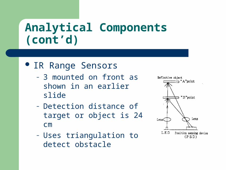
IR Range Sensors– 3 mounted on front as shown in
an earlier slide– Detection distance of target or
object is 24 cm– Uses triangulation to detect
obstacle

Analytical Components (cont’d)
HC12 Microcontroller
PORTA PORTB PORTP
8 bitsIR Detectors
3 bitsIR Range Sensors
3 bits/5 bitsLED’s/Motors
Port Mapping

Analytical Components (cont’d)
PORTB Bit IR Range Sensor Mapping
B0 (LSB) IRR0B1 IRR1B2 IRR2B3 Not UsedB4 Not UsedB5 Not UsedB6 Not UsedB7 (MSB) Not Used
IR Range Sensor Mapping
Front
rear
0 12
PORTA Bit Mapping to IR Detector
A0 (LSB) IRD0A1 IRD1A2 IRD2A3 IRD3A4 IRD4A5 IRD5A6 IRD6A7 (MSB) IRD7
IR Detector Mapping
0
4
26
1
35
7
PORTP Bit MappingP0 (LSB) Status LED0P1 Status LED1P2 Status LED2
P3 H-bridge P1 & P9 (enable)
P4 H-bridge P2P5 H-bridge P7P6 H-bridge P15P7 (MSB) H-bridge P10
Output Port Mappings
Front
rear
HC12
Status LED0
Status LED1
Status LED2
Motor 1
Motor 2

Analytical Components (cont’d)
Seeker Vehicle Analysis– Speed of seeker vehicle will be adjusted to suitable
speed determined upon testing– Vehicle will continuously turn to ensure that the
signal is always detected from the front-most detector
Non-signal based turning will be done on a timed basis

Test Plan
Test each segment separately– Modulated IR emitter and detector circuits
Complete 360º emission of IR signal Proper directional detection of IR signal
– IR range sensors– DC motor control– HC12 code w/out sensors attached
Proper execution of search pattern
– HC12 code w/sensors attached Proper execution of search pattern & interaction w/sensors

Test Plan (cont’d)
Fully assembled testing of seeker and target vehicles– Non-mobile detection of IR signal from target
vehicle– Mobile detection of IR signal from target vehicle– Successful searching, tracking, and tagging of
target vehicle

Power Consumption
PartDissipation
Current (mA)Quantity
Total Current Dissipation (mA)
Power Consumption (W)
HC12 300 1 300 1.5IR LEDs 45 10 450 2.25IR Detectors 0.2 8 1.6 0.008IR Range Sensors 50 3 150 0.75DC Motors 300 2 600 3
7.508Total Power Consumption:

Division Of Work
Task Description Person AssignedCoding JonDC Motor Drive Circuitry & Testing JonModulated IR Emitter and Detector Assembly & Testing WaiIR Range Sensor Assembly & Testing WaiPower Circuitry Design, Construction, and Testing WaiWeb Site WaiSeeker RC sensor and hardware mounting BothTarget RC IR emitting beacon mounting BothProject Testing Both
Work Completed
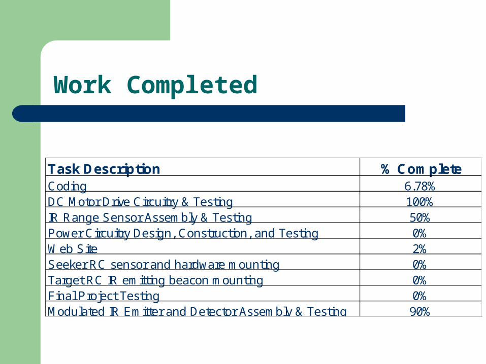
Task Description % CompleteCoding 6.78%DC Motor Drive Circuitry & Testing 100%IR Range Sensor Assembly & Testing 50%Power Circuitry Design, Construction, and Testing 0%Web Site 2%Seeker RC sensor and hardware mounting 0%Target RC IR emitting beacon mounting 0%Final Project Testing 0%Modulated IR Emitter and Detector Assembly & Testing 90%

Work Completed (cont’d)
Modulated IR Emitter Circuit
Component Value/DescriptionU1 555 Timer ICR1 47 ohm resistorR2 470 ohm resistorR3 5k variable resistorC1 0.0047uf ceramic capacitorRLED 82 - 150 ohm resistor
Work Completed (cont’d)
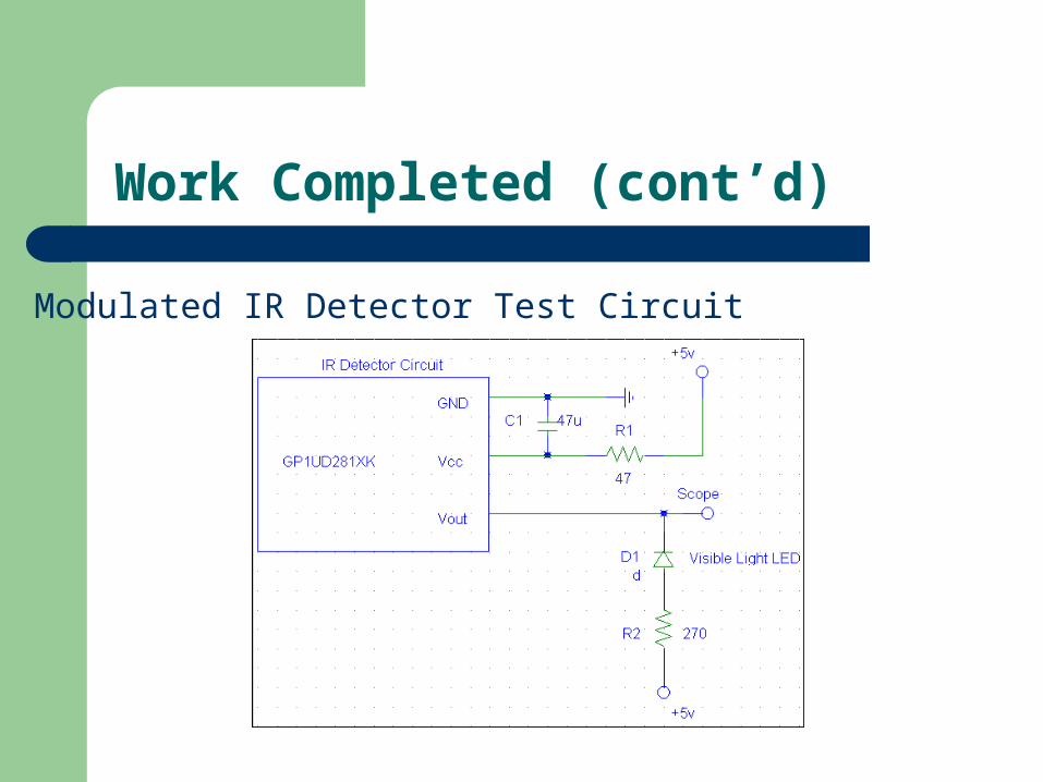
Modulated IR Detector Test Circuit

Work Completed (cont’d)
IR Range Sensor Circuit

Work to be done
Complete IR emitter/detector sensor testing HC12 coding Web page IR range sensor mounting Vehicle construction and hardware mounting Project Testing

Total System Cost
Item Description Qty. Unit Price Actual Cost Our CostRC Car (Seeker) 1 $29.95 $29.95 $29.95RC Car (target) 1 $29.95 $29.95 $29.95HC12 Micro Controller 1 $159.00 $159.00 $0.00IR Range Sensors 3 $13.50 $40.50 $0.00IR LEDs 8 $0.26 $2.08 $2.08IR Receivers 8 $0.83 $6.64 $6.64Motor Batteries 2 $8.00 $16.00 $16.00Other Expenses N/A N/A $50.00 $50.00
$334.12 $134.62Total:

Potential Safety Problems
Stubbed toe

Questions?