Embed Size (px)
Citation preview

2005
SURGE PROTECTIONIN LOW-VOLTAGE
POWER DISTRIBUTION SYSTEMS


INTRODUCTION
I
Director's messageFrom its very beginnings in 1989, the employees of Iskra Za{~ite set out their clear goal: to provide their users with high quality and reliablesolutions in the field of over-voltage protection. Today's results only confirm our efforts.Quality is the basic value respected by all the employees. We aim not only to satisfy our buyers but also to offer excellent products and servicethus bettering their expectations. We have long-standing connections with our buyers and together we determine our long-term goals. We carryout constant product and process improvements and appropriate solutions with the aid of up-to-date technology and efficient tools. One of themajor focuses of the employees is the gaining of new knowledge, therefore intensive training and inclusion of external experts guarantees ahighly qualified staff for the production of demanding projects.Our path is already defined. Customer satisfaction is our long-range aim: no paper work, no delays, no inconsistency with orders and theguarantee of complete solutions requiring minimum buyer participation while simultaneously focusing on their needs.
Vladimir Murko, MScManaging director
Products and serviceThe company's main activities are the development, production and sale of overvoltage protection for:
- low voltage network systems,- telecommunications,- data transmission systems- planning.
Besides overvoltage protection, the company also develops, produces and sells distribution frames and strips for the mounting of over-voltageprotection as well as accessories and measuring aids for the mounting and testing of over-voltage protection, protection components andtelephone lines in telephone exchanges.
Main groups of our production programme
Surge protection for low voltage power distribution systems:Category IEC/VDE
I/BII/CIII/D
Overvoltage protection for telephone exchanges and terminals:- protection modules,- strips,- main distribution frames (MDF),- mounting accessories.
Overvoltage protection for data transmission systems:- for data transmission,- for d.c. power supplies,- for two-line transmission,- for computer networks,- for application in intrinsic electrical circuits.
Elements: gap discharge tubes
Lightning and overvoltage planning:- preparing complete technical solutions for lightning and over-voltage protection according to national and international standards and
regulations,- mounting of entire systems and supervision,- instruction seminars on integrated approach to effective lightning, earthing and surge protection.
Quality controlQuality control in Iskra Za{~ite is the result of common efforts by all the employees who have an influence on the business success, competitivenessand satisfaction of the buyers. We realise that quality gratification is the key to buyer, employee and partner satisfaction.The company was awarded the ISO 9001 certificate in 1989 and superimposed this with the 20-key system which represents one of the mostup-to-date systems for improving quality. The products from the production programme satisfy international standards such as VDE, OVE, IECand UL. A great number of the company's products are patented.

PLANNING OF SURGE PROTECTIVE SYSTEMS
II
General view of surge protective systems and their necessityImmensely fast technological advancement in all fields of science and culture has introduced a lot of devices, even there, where we recentlycouldn't have imagined them. There is a lot of information from all over the world, which has to be correctly linked together and at the sametime swiftly transmitted from one place to another. In today's technical and economical world this is a generally recognized demand, which wecannot reject.It is not our mission to discuss the technological revolution, but we would like to follow and understand it and above all share our knowledgeand experience from the field of surge protective elements and contribute to technical improvement as a whole.In this context it is necessary to see protective devices as a solid shield, which protects objects from strong external interferences, such aslightning strikes.The purpose of installing surge protective modules is that with correct and functional protection in suitable places, a partial or total collapse ofthe system is prevented.
Causes of over-voltagesOver-voltage originates from:
- Atmospheric discharges, which can cause a direct strike in a particular system or as a consequence of induction, transferred to the nearby objects;- Over-voltage due to switching (consequence of connecting and disconnecting of consumers);- Errors in power supply systems (ground contacts) or coincidental connection at different power supply, information and telecommunication systems;- Electric pulls (electrical train, tram, metro …)
Damage statisticsDamage statistics periodically issued by the insurancecompanies, show problems and typology of damages.The largest part of damages on electrical devices is ofover-voltage origin and ranges from 27 % to 35 %regarding the headquarters and territory of insurancecompany.
Terminology for better understanding and selection of over-voltage protection
1. Surge Protection Device (SPD): devices for overvoltage limiting2. Maximum allowed voltage (Uc): maximum allowed (AC or DC) and connection voltage on SPD. At the same time this is its rated voltage.3. Protective voltage level (Up): voltage that occurs on SPDs connectors at presence of exact shape and amplitude impulse4 Residual voltage (URES): peak voltage value at load of SPD with striking current5 Occasional over-voltage (UTOV): over-voltage that occurs in power supply conductor due to system's non linearity or ground contacts. It is
characteristic for its relatively long duration (up to 5s, in some cases up to few hours). It is the most frequent cause for destruction of SPD.6 Impulse current (Iimp): peak value of wave current 10/350 µs. It is used for classification of class I SPDs.7 Rated leak current (In): peak value of wave current 8/20 µs. It is used for classification of class II SPDs.8 Maximum discharge current (Imax) for class II test: crest value of the current through the SPD having an 8/20 waveshape and magnitude
according to the test sequence of the class II operating duty test. Imax is greater than In.9 Combined wave: it is carried out with voltage wave generator 1,2/50 µs. In case of short circuit it turns to wave 8/20 µs. Voltage impulse
is symbolized as Uoc and current at short circuit as Isc. Combined wave is used for classification of class III SPDs.10 Casing protective level (IP): is level of casing protection against invasion of foreign objects or water against parts of the machine that are
under electric power.11 Circuit breaking device of SPDs: is a device that switches off the protective element from the line in case of thermal escape. At the same
time it is also an indicator of damaged SPDs.12 Following current (IF): current, which runs from power supply system after the lapse of striking wave or after reaction of SPDs.13 Flux protection (e.g. fuse): is a part of electrical installation, placed in front of SPDs. It serves as protective element in case of inability to
react or damage of circuit breaking device of protective element.14 Voltage strength (Uw): according to voltage strength devices are classified into following four classes: 1500 V, 2500 V, 4000 V in 6000 V
considering the direction of electricity flux (classes are determined under IEC 60664-1).15 MB: Main distribution board16 SB: Secondary distribution board17 SA: Socket close to apparatus
Ratio between different types of damage (Source: German Insurance Company)

III
Atmospheric dischargesAtmospheric discharge is transient, a discharge with high current intensity, which is caused by charge transition between earth and a cloud,between clouds or between cloud and earth.
More than half of all strikes take place between the clouds, which is called IC (inter-cloud) discharge. The discharge cloud-earth, also called CD(cloud-ground) was a subject of many studies, because it is of life importance (e.g. as a cause of death, harmful influences on power supply andtelecommunication lines etc.).
There are two different modes of CG atmospheric discharges:
1. Negative charge towards positive ground (negative atmospheric discharge),2. Positive charge (ground) towards negative cloud (positive atmospheric discharge).
Up to 90 % of all atmospheric discharges can be ascribed to negative ones and approximately 10 % to positive ones.
Lightning densityLightning density towards ground is defined as a number of lightning strikes towards ground per square kilometre per year and should bedetermined with lightning allocation system measurement.
If the lightning density towards ground (Ng) isnot given, we can estimate it with the followingequation:
Ng = 0,04 . Td1.25 /km2/per year
Ng = number of expected atmospheric dischargesper year per square kmTd = number of stormy days per year; taken fromisokeraunic maps
(Source: EN 61024-1)
Number of stormy days per year (Td) in Slovenia
Regarding the lightning threat on macro levelSlovenia can be divided into three regions:
1. Ng = 2.5 - 4
Comprises a triangle: Ljubljana - the Alpineworld - the Adriatic sea and is coloured asa region of great threat.
2. Ng = 1.5 - 2.5
This region comprises central Sloveniabetween the Ljubljana basin and Maribor. Itis classified into a moderately threatenedregion.
3. Ng = 1 - 1.5
This category comprises the Drava plainwith the Pomurje region. It is recognisedas a threatened region.

IV
Expected atmospheric discharge magnitudesMaximum atmospheric discharge magnitudes occur from a few 10 kA to 200 kA. See graph 1 which depicts statistical data on intensity amplitudeat discharging.
Comment: the greatest certainty is that the amplitudes of atmospheric discharges are in the range between 10 - 35 kA.
Threat and admissible damage prevalence due to atmospheric discharges on objects
The purpose of protection against lightning is to minimize the damage risk under admissible maximum level. This means, that it is necessary tofulfil the following requirements:
R ≤ RT
RT = tolerable level riskR = total risk
Damages caused by atmospheric discharges are as follows:
1. loss of human lives (R1);2. unacceptable mains failures of public power supply systems (R2);3. irretrievable destruction of cultural heritage (R3);4. loss of economic values (R4).
Probability histogram of atmospheric discharge magnitudes
Types of loss resulting from different types of damage

V
Guide for selecting LPS
LegendNg = ground flash density per year per km2
If not known, calculate from number of stormy days
Ae = structure collective areaE = protection level efficiencyNd = average lightning strikes in structure per
yearE’ = protection levelNc = permitted risk of damage
(determined by national standard)LPS =Lightning Protection System
Calculation of structure collective area
Ae= L . W + 6 . H (L +H) + 9π . H2
Ae= 0,095 km2
Nd= Ng . Ae
Nd= 0,2 . 10-3
Nd ≤ Nc
No
E´= 1 - Nc–––Nd
E´= 1 - 1 . 10-5
0,2 . 10-3
E´= 0,995
0,95 < E ≤ 0,98 Protection level I0,90 < E ≤ 0,95 Protection level II0,80 < E ≤ 0,90 Protection level III0 < E ≤ 0,80 Protection level IV
E > 0,98 protection level I and additional protective measures
Source: EN 61024-1
Active ProtectionFaraday Cage

INSTALLATION AND CHOICE OF SPD
VI
a) NetworksIn accordance with IEC 364-4-41 (1992) a low voltage distribution system is usuallycharacterized from electricity source to terminal equipment with the following:
- grounded power supply source (e.g. low voltage connection of local network transformer);- grounded system of exposed conductible parts in consumer electrical installations.
Through this three basic types of systems could be defined as distribution systems:- TN system;- TT system;- IT system.
Used abbreviations have the following meaning:
The first letter describes grounded system of power-feeding electricity source.T - direct grounding of power supply source single point (primarily connecting point of
transformer winding);I - isolation of all active parts from ground or connection of single source point of
electricity to ground over some sort of impedance.The second letter describes grounded system of exposed conductible parts of electrical installation
T - exposed conductible part is directly grounded independent of eventual existinggrounded feeding point
N - exposed conductible part is directly connected to grounding electrode (grounding resistor)Further letters describe an arrangement of neutral and protective conductors
S - neutral and protective conductor are separatedC - neutral and protective conductor are connected
Hence it follows that there are three possible TN systems: TN-S, TN-C and TN-C-S
The following protective devices can be installed in the different systems:- Over-current protective device,- Residual protective device (r. c. d.)- Insulation monitoring device- Fault-voltage-operated protective device
As mentioned before, it is necessary to co-ordinate the type of system grounding and thecharacteristics of protective conductors and protective devices. The following protectivedevices are applicable in the different systems:
TN-S system
TN-C system
TN-C-S system
TT system
IT system
TN System- Over-current protective device;- Residual current protective device.
TT System- Over-current protective device;- Residual current protective device,- Fault-voltage-operated protective device.
IT System- Over-current protective device;- Residual current protective device,- Insulation monitoring device- Fault-voltage-operated protective device
Common Power DistributionSystems (Europe)

VII
Common Power Distribution Systems (North America, Asia, Latin America)
Description Source Configuration Typical Supply Voltages
Single Phase1Ph, 110V, 120V, 220V, 240V2W+G (L-N)
Single Phase 120/240V1Ph, 3W+G (L-N / L-L)Also known as Split phase or Edison system
Three Phase WYE 480Vwithout neutral (L-L)3Ph Y, 4W+G
Three Phase WYE with 120/208V, 220/380V,neutral 230/400V, 240/415V,3Ph Y, 4W+G 277/480V, 347/600V
(L-N / L-L)
Delta High leg 120/240V3Ph, 4W+G (L-N / L-L)
Delta Ungrounded 240V, 480V3Ph , 3W+G (L-L)
Delta Grounded corner 240V, 480V3Ph , 3W+G (L-L)
VIII
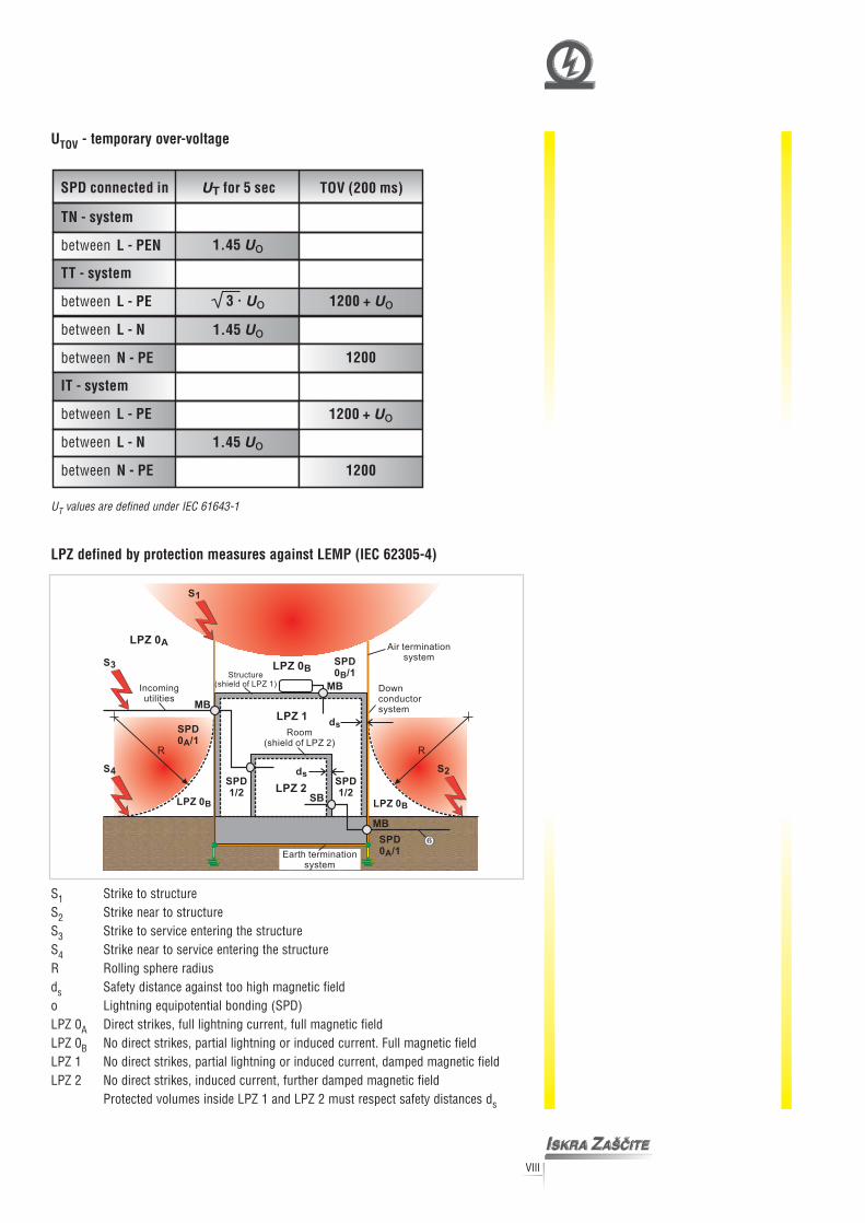
UTOV - temporary over-voltage
UT values are defined under IEC 61643-1
LPZ defined by protection measures against LEMP (IEC 62305-4)
S1 Strike to structureS2 Strike near to structureS3 Strike to service entering the structureS4 Strike near to service entering the structureR Rolling sphere radiusds Safety distance against too high magnetic fieldo Lightning equipotential bonding (SPD)LPZ 0A Direct strikes, full lightning current, full magnetic fieldLPZ 0B No direct strikes, partial lightning or induced current. Full magnetic fieldLPZ 1 No direct strikes, partial lightning or induced current, damped magnetic fieldLPZ 2 No direct strikes, induced current, further damped magnetic field
Protected volumes inside LPZ 1 and LPZ 2 must respect safety distances ds

METHODS AND DIRECTIONS FOR PLANNING SURGE VOLTAGE SYSTEMS IN NN INSTALLATIONS
IX
1. We determine the protective zone (as per IEC 62 305 Ed. 1) and the point of crossing. Thepoints of crossing in the protective zone and the installation points MB, SB, SA are also theplaces where surge protection devices SPDs are installed.
POINTS OF CROSSING IN PROTECTED ZONESAt point MB (main distribution board) which is at crossing OB/1 and is subject to partialdirect lightning strikes, a class 1 SPD must be installed. Class 1 SPDs are those declared forcurrent arrester pulses 10/350 µs.
2. Determining expected current values depending on typical models.
2.a. Model of exposed structure ( radio base stations, waterworks, RTV transmitter, etc.)Theoretically current sharing in case of direct lightning strike into building
50% - LPS
50% - power supply
IIMP /2 = 200 kA/2 = 25 kAn 4
IIMP /pole = 25 kA
n = number of conductors (for easier calculation the influence of gas, water and other conductors are omitted).
In each conductor a maximum current value of 25 kA is expected.
2.b. Model of two structures (earthing resistance is the same) close together.Theoretically current sharing in case of direct lightning strikeinto building
50 % - LPS
50 % - IIMP = IIMP /2 = 100 kA = 50kA1+ RA 2
RB
IIMP/pole = IIMP = 50 kA = 12,5 kAn 4
With this model we can expect the same distribution in bothstructures and in all conductors and an expected current of12.5kA per conductor.
Legend: MB = Main distribution board; SB = Sub-distribution board; SA = Socket outlet

X
2.c. Model of two structures (earthing resistance is not thesame). Normally the structures are not in close vicinity.
Theoretically current sharing in case of direct lightning strike into building
50 % - LPS
50 % - IIMP = IIMP /2 = 100 kA = 80 kA 11+ RA 1,25
RB
Ipole = IIMP = 80 = 20 kA 1n 4
IIMP = IIMP /2 = 100 kA = 20 kA 21+ RA 5
RB
Ipole = IIMP = 20 = 5kA 2n 4
Model 2.c. is the most common model with characteristic distribution of current, i.e. 40 %in the structure with lower earthing resistance and 10% in the one with the higher resistancewith equivalent distribution of current along the individual conductors.
Depending on model type (2.a, 2.b., 2.c.) it is necessary to determine the closest exampleand accordingly choose the model and maximum expected current/pole.For guidance use the ISKRA catalogue which covers all characteristic values depicted in thethree models.
For TT systems in three-phase systems IN-PE = 4 . IIMP /pole
For single-phase systems IN-PE = 2 . IIMP / pole
3. Establishing in which group of electromagnetic immunity (EMC), according to IEC 61000-4-5,do the protected devices belong.
Arrangement according to IEC 61000-4-5:
Uoc (1.2/50) Isc (8/20)
1 4kV 2kA
2 2kV 1kA
3 1kV 0,5kA
4 0,5kV 0,25kA
Uoc and Isc so are values with which EMC immunity is tested
4. Determining distance ( l ) between protected device and SPD.
0A = direct lightning strike zone0B = partial direct strikes zone0B/1 = installation point of SPD class Il = distance between SPD and protected device
XI
5. Selection of SPD fulfilling the following demands
Uprot ≤ Ui
Uprot = Up + ∆U
Up = protection level of SPD (kV)∆U = inductive voltage dropUi = dielectric strength of device (kV) in accordance with installation category (from 1 to IV)Uprot = voltage sensed by the device
Dielectric values according to category
Category Dielectric strength (kV)I 6 kVII 4 kVIII 2.5 kVIV 1.5 kV
Dielectric strength category must be given by the manufacturer.
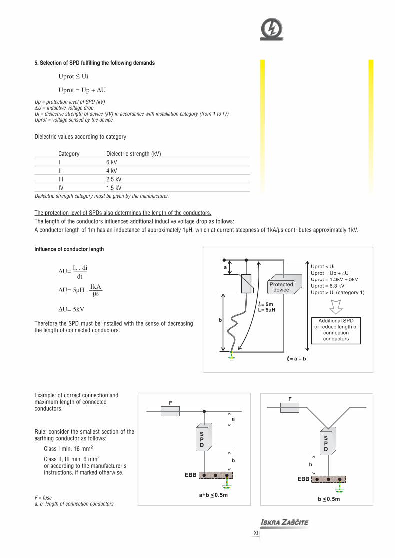
The protection level of SPDs also determines the length of the conductors.The length of the conductors influences additional inductive voltage drop as follows:A conductor length of 1m has an inductance of approximately 1µH, which at current steepness of 1kA/µs contributes approximately 1kV.
Influence of conductor length
∆U= L . di––––dt
∆U= 5µH . 1kA––––µs
∆U= 5kV
Therefore the SPD must be installed with the sense of decreasingthe length of connected conductors.
Rule: consider the smallest section of theearthing conductor as follows:
Class I min. 16 mm2
Class II, III min. 6 mm2
or according to the manufacturer'sinstructions, if marked otherwise.
F = fusea, b: length of connection conductors
Example: of correct connection andmaximum length of connectedconductors.

XII
The table allows easier defining of needs for secondary and cascade selection of SPDs.Manufacturers usually give Up values only for In, therefore, the depicted diagram of Up flowis useful data and facilitates work.
6. At point MB (main distribution board) install SPDs class I.They are for effective protection of devices classified in installation categories I and II (6kVand 4kV).Determining distance between SPD installed in point MB (SPD class I) and protected device.If condition Uprot < Ui/2 is not reached, it is necessary to install an additional SPD.
7. At point SB (sub-distributor) an SPD class II is installed. These are installed as protectionagainst induced voltage, which occurs in the installations. The SPDs must comply to theminimum demand In = 5kA; in connection 1+1 between N - PE 10 kA; in connection 3 +1the SPD must withstand 20 kA between N -PE.
SPDs class II can be used only in crossings from zone I/II (always following SPD class I ).
8. Determining distance between SPD (class II ) on point SB and protected devices.
Condition for proper protection:
Uprot2 < Ui/2
In this case the SPD class II has successfully protected installation category III and II.Note: SPDs class II can only be installed if the incoming utilities are within the protected zone OB.
9. At point SA (the point directly in front of the protected device) an SPD class III is installed.They are always installed after the SPD class I and II.
The indicated order of SPD installation is required for attaining effective protection even inthe case of unfavourable installation conditions.
1. flow of Up at indirect lightning strikes (marked by wave 8/20)2. flow of Up at direct lightning strikes (marked by wave 10/350)
Diagram of characteristic values Up (kV) in dependence of current (kA) for ISKRA SPDs (Uc = 320 V)

XIII
How to select proper SPDs
Constructional typology of products
- SPD with varistor- no following current IF- quick reactive times tA (≤ 25 µs)- reacts also to very low over-voltages- high discharge current capacity up to 75 kA 10/350 µs
- SPD with gas discharge tube- high discharge current capacity up to 100 kA 10/350 µs- no exhaust- used in TT systems (as galvanic separation between N-PE conductors)
- SPD with serial arrangement of varistor and gas discharge tube- no following current IF- reaction time tA (≤ 100 µs)- reacts also to low over-voltages- current discharge capacity up to 25 kA 10/350 µs- low Up level up to 600V for 230/400V power supply systems

XIV
References
1. IEC 61024 - 1; 1990, modified; Protection of structures against lightning - Part 1;General principles
2. Draft IEC 61643-2; 37A/69/CDV 1998; Surge protective devices connected to lowvoltage power distribution systems; Part 2: Selection and application principles
3. IEC 61662 Assessment of the risk of damage due to lightning
4. IEC 61312-1 Protection against lightning electromagnetic impulse; Part 1: Generalprinciple
5. Draft IEC 62066: 64/103/CD, 1998; General basic information regarding surge over-voltages and surge protection in low voltage AC power systems
6. IEC 61643 Surge protective devices connected to low voltage power distributionsystems; Part 1: Performance requirements and testing methods of SPD's; Firstedition, 1998
7. ÖVE NORM E 8001-1
8. IEC 60364-4-443 Electrical installations of buildings; Part 4: Protection for safetyChapter 44; Protection against over-voltages Section 443; Protection against over-voltages of atmospheric origin due to switching; Second edition
9. IEC 61000-4-5: 1995 Electromagnetic compatibility (EMC) - Part 4: Testing andmeasurements techniques; Section 5: Surge immunity test
10. IEC 62305-1 Ed.1 Lightning protection


Type
UcInImaxIpeak
tA
In accordance withCategory IEC / VDEMax. continuous operating
(AC/DC)Nominal discharge current (8/20)Max. discharge current (8/20)Current peak value (10/350)Specific energyChargeProtection level Up - at In (8/20)
- at Iimp (10/350)Follow currentResponse timeResidual current atThermal decoupler
Back-up fuse (if mains > 250 A)Short-circuit withstandTemperature rangeCross-section of connection wireMountingDegree of protectionCasing materialDimensions
Code
voltage
Uc
Torque
Weight per unit
Remote signalisationSwitching capabilityCross-section of connection wireTorqueWeight per unitCode
Packaging - single / Dimensions
I
I
Additional data for TEC R 75
f
PE
PRO BS
PRO BSTEC 75PRO BSTEC 75
1
PRO BSTEC (R) 75/xxx150 275 320 440
IEC-61643-1I, II / B, C
150/200V 275/350V 320/420V 440/580V120kA 12300kA 300kA 300kA 250kA7
0.8kV 1.3kV 1.5kV 1.9kV0.7kV 1.1kV 1.2kV 1.7kV
NO< 25ns
< 3.5mAYES
max. 4.5Nm250A gL
25kA / 50Hz- 40 C ….+80 C
single-strand 35mm ; multi-strand 25mmindors on top hat fixing rail 35mm
IP 20thermoplastic; extinguishing degree
DIN 43880 3TE
0kA 120kA 100kA
5kA 75kA 75kA 50kA
UL94 V-0
YESAC: 250V/0.5A;125V/3A
max. 1.5mm0.25Nm
o o
2 2
2
1.4MJ/ 625kJ/
37.5As 3 25As
475g 610g 630g 580g502 041 502 043 502 045 502 047
� �1.4MJ/ 1.4MJ/
7.5As 37.5As
485g 620g 640g 590g502 049 502 051 502 053 502 055
� �
Technical data
Category IEC / VDE
PROTEC BS 75 is an overvoltage arrester for protection against partial direct and indirectatmospheric discharges and it is intended for protection in zones 0 - 1.
: I, II / B, CLocation of use: Main distribution board (MB)Protection againstthermal runaway: PROTEC BS 75 contains three
Remote signalisation:
A
separate varistor couplingswith separate disconnection devices, which indicate thedefect through the common indicator.
varistor coupling in which the defect arises.It functions immediately after the defect, regardless of the
L/N
L/N
PE
PE
>250A gL
250A gLmin. recommendedcross section 16 mm2
Selection of back-up fuse
SURGE PROTECTIVE DEVICES
LOW-VOLTAGE POWER DISTRIBUTION SYSTEMS
52.5
68
90
14RC 11
12

Type
UcInImaxIpeak
tA
In accordance withCategory IEC / VDEMax. continuous operating
(AC/DC)Nominal discharge current (8/20)Max. discharge current (8/20)Current peak value (10/350)Specific energyChargeProtection level Up - at In (8/20)
- at Iimp (10/350)Follow currentResponse timeResidual current atThermal decoupler
Back-up fuse (if mains > 250 A)Short-circuit withstandTemperature rangeCross-section of connection wireMountingDegree of protectionCasing materialDimensions
Code
voltage
Uc
Torque
Weight per unit
Remote signalisationSwitching capabilityCross-section of connection wireTorqueWeight per unitCode
Packaging - single / Dimensions
I
I
Additional data for TEC R 50
f
PE
PRO BS
PRO BSTEC 50PRO BSTEC 50
2
PRO BSTEC (R) 50/xxx150 275 320 440
IEC-61643-1I, II / B, C
150/200V 275/350V 320/420V 440/580V80kA 8
200kA 200kA 200kA 150kA50
25As 2 20As
NO< 25ns< 2.5mA
YESmax. 4.5Nm
250A gL25kA / 50Hz
- 40 C ….+80 Csingle-strand 35mm ; multi-strand 25mm
indors on top hat fixing rail 35mmIP 20
thermoplastic; extinguishing degreeDIN 43880 2TE
315g 405g 425g 380g502 061 502 063 502 065 502 067
0kA 80kA 80kA
kA 50kA 50kA 40kA
5As 25As
UL 94 V-0
YESAC: 250V/0.5A;125V / 3A
max. 1.5mm0,25Nm
325g 415g 435g 390g502 069 502 071 502 073 502 075
108mm x 76mm x 47mm
o o
2 2
2
625kJ/ 400kJ/
0.8kV 1.3kV 1.5kV 1.9kV0.7kV 1.1kV 1.2kV 1.7kV
� �625kJ/ 625kJ/� �
Technical data
Category IEC / VDE
PROTEC BS 50 is an overvoltage arrester for protection against partial direct and indirectatmospheric discharges and it is intended for protection in zones 0 - 1.
: I, II / B, CLocation of use: Main distribution board (MB)Protection againstthermal runaway: PROTEC BS 50 contains
Remote signalisation:
A
two separate varistor couplings withseparate disconnection devices, which indicate the defectthrough a common indicator.It functions immediately after the defect, regardless of thevaristor coupling in which the defect arises.
L/N
L/N
PE
PE
>250A gL
250A gLmin. recommendedcross section 16 mm2
Selection of back-up fuse
SURGE PROTECTIVE DEVICES
LOW-VOLTAGE POWER DISTRIBUTION SYSTEMS
35
68
90
14RC 11
12

Type
UcInImaxIpeak
tA
In accordance withCategory IEC / VDEMax. continuous operating
(AC/DC)Nominal discharge current (8/20)Max. discharge current (8/20)Current peak value (10/350)Specific energyChargeProtection level Up - at In (8/20)
- at Iimp (10/350)Follow currentResponse timeResidual current atThermal decoupler
Back-up fuse (if mains > 250 A)Short-circuit withstandTemperature rangeCross-section of connection wireMountingDegree of protectionCasing materialDimensions
Code
voltage
Uc
Torque
Weight per unit
Remote signalisationSwitching capabilityCross-section of connection wireTorqueWeight per unitCode
Packaging - single / Dimensions
I
I
Additional data for TEC R 35
f
PE
PRO BS
PRO BSTEC 35PRO BSTEC 35
3
PRO BSTEC (R) 35/xxx150 275 320 440
IEC-61643-1I, II / B, C
150/200V 275/350V 320/420V 440/580V50kA 5
100kA 100kA 100kA 70kA3
17.5As 12.5As0.8kV 1.3kV 1.5kV 1.9kV0.6kV 1.0kV 1.1kV 1.6kV
NO< 25ns< 2.5mA
YESmax. 4.5Nm
250A gL25kA / 50Hz
- 40 C ….+80 Csingle-strand 35mm ; multi-strand 25mm
indors on top hat fixing rail 35mmIP 20
thermoplastic; extinguishing degreeDIN 43880 2TE
270g 340g 355g 320g502 021 502 023 502 025 502 027
0kA 50kA 50kA
5kA 35kA 35kA 25kA
17.5As 17.5As
UL 94 V-0
YESAC: 250V/0.5A;125V / 3A
max. 1.5mm0,25Nm
280g 350g 365g 340g502 029 502 031 502 033 502 035
108mm x 76mm x 47mm
o o
2 2
2
306kJ/ 156kJ/� �306kJ/ 306kJ/� �
Technical data
Category IEC / VDE
PROTEC BS 35 is an overvoltage arrester for protection against partial direct and indirectatmospheric discharges and it is intended for protection in zones 0 - 1.
: I, II / B, CLocation of use: Main distribution board (MB)Protection againstthermal runaway: PROTEC BS 35 contains
Remote signalisation:
A
two separate varistor couplings withseparate disconnection devices, which indicate the defectthrough a common indicator.It functions immediately after the defect, regardless of thevaristor coupling in which the defect arises.
L/N
L/N
PE
PE
>250A gL
250A gLmin. recommendedcross section 16 mm2
Selection of back-up fuse
SURGE PROTECTIVE DEVICES
LOW-VOLTAGE POWER DISTRIBUTION SYSTEMS
35
68
90
141112
RC

35
68
90
Type
UcInImaxIpeak
tA
In accordance withCategory IEC / VDEMax. contunuous operating
(AC/DC)Nominal discharge current (8/20)Max. discharge current (8/20)Current peak value (10/350)Specific energyChargeProtection level Up - at In (8/20)
- at Iimp (10/350)Follow currentResponse timeResidual current atThermal decoupler
Back-up fuse (if mains > 250 A)Short-circuit withstandTemperature rangeCross-section of connection wireMountingDegree of protectionCasing materialDimensions
Code
voltage
Uc
Torque
Weight per unit
Remote signalisationSwitching capabilityCross-section of connection wireTorqueWeight per unitCode
Packaging - single / Dimensions
I
I
Additional data for TEC R 25
f
PE
PRO BS
PRO BSTEC 25PRO BSTEC 25
4
PRO BSTEC (R) 25/xxx150 275 320 440
IEC-61643-1I, II / B, C
150/200V 275/350V 320/420V 440/580V4 40kA 4 40kA80kA 80kA 80kA 60kA
2
12.5As 10As0.8kV 1.3kV 1.5kV 1.9kV0.6kV 1.0kV 1.1kV 1.6kV
NO< 25ns< 2.5mA
YESmax. 4.5Nm
250A gL25kA / 50Hz
- 40 C ….+80 Csingle-strand 35mm ; multi-strand 25mm
indors on top hat fixing rail 35mmIP 20
thermoplastic; extinguishing degreeDIN 43880 2TE
502 081 502 083 502 085 502 087
0kA 0kA
25kA 5kA 25kA 20kA156kJ/ 156kJ/ 156kJ/ 100kJ/
12.5As 12.5As
UL 94 V-0
YESAC: 250V/0.5A; 125V / 3A
max. 1.5mm0,25Nm
235g 280g 290g 270g502 089 502 091 502 093 502 095
108mm x 76mm x 47mm
� � � �
o o
2 2
2
225g 270g 280g 260g
Technical data
Category IEC / VDE: I, II / B,C
contains
Remote signalisation:
Location of use: Main distribution board (MB)Protection againstthermal runaway: PROTEC BS 25
PROTEC BS 25 is an overvoltage arrester for protection against partial direct and indirectatmospheric discharges and it is intended for protection in zones 0 - 1.A
two separate varistors withseparate disconnection devices, which indicate the defectthrough a common indicator.It functions immediately after the defect, regardless of thevaristor coupling in which the defect arises.
L/N
PE
PE
L/N
>250A gL
250A gLmin. recommendedcross section 16 mm2
Selection of back-up fuse
SURGE PROTECTIVE DEVICES
LOW-VOLTAGE POWER DISTRIBUTION SYSTEMS
141112
RC

Type
UcInImaxIpeak
tA
Certified under; tested toCategory IEC / VDEMax. contunuous operating
(AC/DC)Nominal discharge current (8/20)Max. discharge current (8/20)Current peak value (10/350)Specific energyChargeProtection level Up - at In (8/20)
- at Iimp (10/350)Follow currentResponse timeResidual current atThermal decoupler
Back-up fuse (if mains > 250 A)Short-circuit withstandTemperature rangeCross-section of connection wireMountingDegree of protectionCasing materialDimensions
Code
voltage
Uc
Torque
Weight per unit
Remote signalisationSwitching capabilityCross-section of connection wireTorqueWeight per unitCode
Packaging - single / Dimensions
I
I
Additional data for TEC R 25
f
PE
PRO B
PRO BTEC 25PRO BTEC 25
5
PRO BTEC (R) 150/xxx - 25150 275 320 440
IEC-61643-1I, II / B, C
150/200V 275/350V 320/420V 440/580V4 40kA 4 40kA
100kA 100kA 100kA 75kA2
12.5As 10As0.7kV 1.3kV 1.4kV 2.0kV0.7kV 1.1kV 1.2kV 1.7kV
NO< 25ns< 2.5mA
YESmax. 4.5Nm
250A gL25kA / 50Hz
- 40 C ….+80 Csingle-strand 35mm ; multi-strand 25mm
indors on top hat fixing rail 35mmIP 20
thermoplastic; extinguishing degree 5VADIN 43880 2TE
245g 300g 325g 295g502 001 502 003 502 005 502 007
0kA 0kA
25kA 5kA 25kA 20kA156kJ/ 156kJ/ 156kJ/ 100kJ/
12.5As 12.5As
UL 94-
YESAC: 250V/0.5A; 125V / 3A
max. 1.5mm0,25Nm
255g 310g 335g 305g502 009 502 011 502 013 502 015
108mm x 76mm x 47mm
� � � �
o o
2 2
2
Technical data
Category IEC / VDE: I, II / B,C
Remote signalisation:
Location of use: Main distribution board (MB)Protection againstthermal runaway: PROTEC B 25 contains two separate disconnecting devices,
which optically signalizes failure of one or both varistorcouplings.This solution enables, that in spite of one varistor couplingfailure, the other coupling is still in function.
PROTEC B 25 is an overvoltage arrester for protection against partial direct and indirectatmospheric discharges and it is intended for protection in zones 0 - 1.A
It functions immediately after the defect, regardless of thevaristor coupling in which the defect arises.
L/N
PE
PE
L/N
12RC
11
>250A gL
250A gLmin. recommendedcross section 16 mm2
Selection of back-up fuse
35
68
90
SURGE PROTECTIVE DEVICES
LOW-VOLTAGE POWER DISTRIBUTION SYSTEMS

35
68
90
PRO BSTUBEPRO BSTUBE
Category IEC / VDE: I, II / B,CMain distribution board (MB)Location of use:
PROTUBE BS is an overvoltage arrester for protection against partial direct and indirectatmospheric discharges. It is used as a galvanic separation between N-PE conductor in 1+1 or 3+1systems (TT network).PROTUBE BS is intended for protection in zones 0 - 1.A
NN
N PE
Type
UcInImaxIpeak
tA
In accordance withCategory IEC / VDEMax. continuous operating
(AC/DC)Nominal discharge current (8/20)Max. discharge current (8/20)Current peak value (10/350)Specific energyChargeProtection level Up
- at (1.2/50)Follow currentResponse time
Temperature rangeCross-section of connection wireMountingDegree of protectionCasing materialDimensions
Code
voltage
Torque
Weight per unit
Packaging - single / Dimensions
If
- at In (8/20)
Thermal decoupler
Back-up fuseShort-circuit withstand
Residual current at Uc
Remote signalisationSwitching capabilityCross-section of connection wireTorqueWeight per unitCode
I
Additional data for TUBE
PE
PRO BS
PRO BSTUBEIEC-61643-1
kA
single-strand 35mm ; multi-strand 25mm
UL 94 V-0
//////
I, II / B, C
255V100kA160kA100
2.5MJ/
50As/
1.2kV100A
100ns//
max. 4.5Nm//
- 40 C ….+80 C
indors on top hat fixing rail 35mmIP 20
thermoplastic; extinguishing degreeDIN 43880 2TE
260g503 017
�
RMS
o o
2 2
Technical data
6
SURGE PROTECTIVE DEVICES
LOW-VOLTAGE POWER DISTRIBUTION SYSTEMS
108mm x 76mm x 47mm

35
68
90
PRO B2STUBEPRO B2STUBE
Category IEC / VDE: I, II / B,CMain distribution board (MB)Location of use:
PROTUBE B2S is an overvoltage arrester for protection against partial direct and indirectatmospheric discharges. It is used as a galvanic separation between N-PE conductor in 1+1 or 3+1systems (TT network).PROTUBE B2S is intended for protection in zones 0 - 1.A
NN
N PE
Type
UcInImaxIpeak
tA
In accordance withCategory IEC / VDEMax. continuous operating
(AC/DC)Nominal discharge current (8/20)Max. discharge current (8/20)Current peak value (10/350)Specific energyChargeProtection level Up
- at (1.2/50)Follow currentResponse time
Temperature rangeCross-section of connection wireMountingDegree of protectionCasing materialDimensions
Code
voltage
Torque
Weight per unit
Packaging - single / Dimensions
If
- at In (8/20)
Thermal decoupler
Back-up fuseShort-circuit withstand
Residual current at Uc
Remote signalisationSwitching capabilityCross-section of connection wireTorqueWeight per unitCode
I
Additional data for TUBE
PE
PRO B2S
PRO B2STUBEIEC-61643-1
kA
single-strand 35mm ; multi-strand 25mm
UL 94 V-0
//////
I, II / B, C
255V50kA
100kA50
625kJ/
25As/
1.2kV100A
100ns//
max. 4.5Nm//
- 40 C ….+80 C
indors on top hat fixing rail 35mmIP 20
thermoplastic; extinguishing degreeDIN 43880 2TE
235g503 011
�
RMS
o o
2 2
Technical data
7
SURGE PROTECTIVE DEVICES
LOW-VOLTAGE POWER DISTRIBUTION SYSTEMS
108mm x 76mm x 47mm

Category IEC / VDE
PROBLOC BS 100 (1+1) is an overvoltage arrester for protection against partial direct andindirect atmospheric discharges and it is intended for protection in zones 0 - 1.
: I, II / B,C
Protection againstthermal runaway: PROBLOC BS 100 (1+1) contains two
Remote signalisation:
Location of use: Main distribution board (MB)
A
separate varistorcouplings with separate disconnection devices, whichindicate the defect through the common indicator.It functions immediately after the defect, regardless of thevaristor coupling in which the defect arises.
L
L
N
N
PE
PE
PRO BSBLOC 100 (1+1)PRO BSBLOC 100 (1+1)
56
570g 660g 680g 635g
504 105 504 107 504 109 504 111
0g 650g 670g 625g
504 097 504 099 504 101 504 103
YES
AC: 250V/0.5A; 125V / 3A
max. 1.5mm
0,25Nm
2
PRO BSBLOC (R) 100/xxx (1+1)
150 275 320 440
IEC-61643-1
I, II / B, C
150/200V 275/350V 320/420V 440/580V
50/100kA 40/100kA
0.8kV 1.3kV 1.5kV 1.9kV
1.2kV 1.2kV 1.2kV 1.2kV
100ARMS< 25ns/100ns
YES / -
max. 4.5Nm
250A gL / -
25kA/50Hz / -
- 40 C ….+80 C
indors on top hat fixing rail 35mm
IP 20
thermoplastic; extinguishing degree UL 94 V-0
DIN 43880 5TE
80/100kA 80/100kA 80/100kA 80/100kA
200/160kA 150/160kA
625kJ/ /2.5MJ/ 400kJ/ /2.5MJ/
25As/50As 20As/50As
single-strand 35mm ; multi-strand 25mm
� � � �
o o
2 2
/
Technical data
Type
Uc
In accordance with
Category IEC / VDE
Max. continuous operating(AC/DC)
Protection level Up - at In (8/20) (MOV)
- at (1.2/50) (GDT)
Thermal decoupler
Back-up fuse (if mains > 250 A)
Short-circuit withstand
Temperature range
Cross-section of connection wire
Mounting
Degree of protection
Casing material
Dimensions
Code
voltage
Nominal discharge current (8/20) (MOV/GDT)
Max. discharge current (8/20) (MOV/GDT)
Current peak value (10/350) (MOV/GDT)
Specific energy (MOV/GDT)
Charge (MOV/GDT)
Follow current (GDT)Response time (MOV/GDT)
Torque
Weight per unit
(1+1)
Remote signalisation
Switching capability
Cross-section of connection wire
Torque
Weight per unit
Code
Packaging - single / Dimensions
InImaxIpeak
IftA
Additional data for BLOCPRO BSR 100
Residual current at Uc IPE
8
>250A gL
250A gLmin. recommendedcross section 16 mm2
Selection of back-up fuse
SURGE PROTECTIVE DEVICES
LOW-VOLTAGE POWER DISTRIBUTION SYSTEMS
14RC 11
12
87.5
90
68
Category IEC / VDE
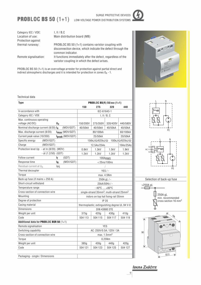
PROBLOC BS 50 (1+1) is an overvoltage arrester for protection against partial direct andindirect atmospheric discharges and it is intended for protection in zones 0 - 1.
: I, II / B,C
Protection againstthermal runaway: PROBLOC BS 50 (1+1) contains
Remote signalisation:
Location of use: Main distribution board (MB)
A
varistor coupling withdisconnection device, which indicate the defect through thecommon indicator.It functions immediately after the defect, regardless of thevaristor coupling in which the defect arises.
L
L
N
N
PE
PE
PRO BSBLOC 50 (1+1)PRO BSBLOC 50 (1+1)
375
385g 430g 440g 420g
504 121 504 123 504 125 504 127
g 420g 430g 410g
504 113 504 115 504 117 504 119
YES
AC: 250V/0.5A; 125V / 3A
max. 1.5mm
0,25Nm
2
PRO BSBLOC (R) 50/xxx (1+1)
150 275 320 440
IEC-61643-1
I, II / B, C
150/200V 275/350V 320/420V 440/580V
25/50kA 20/50kA
0.8kV 1.3kV 1.5kV 1.9kV
1.2kV 1.2kV 1.2kV 1.2kV
100ARMS< 25ns/100ns
YES / -
max. 4.5Nm
250A gL / -
25kA/50Hz / -
- 40 C ….+80 C
indors on top hat fixing rail 35mm
IP 20
thermoplastic; extinguishing degree UL 94 V-0
DIN 43880 3TE
40/50kA 40/50kA 40/50kA 40/50kA
80/100kA 60/100kA
156kJ/ /625kJ/ 100kJ/ /625kJ/
12.5As/25As 10As/25As
single-strand 35mm ; multi-strand 25mm
� � � �
o o
2 2
/
Technical data
Type
Uc
In accordance with
Category IEC / VDE
Max. continuous operating(AC/DC)
Protection level Up - at In (8/20) (MOV)
- at (1.2/50) (GDT)
Thermal decoupler
Back-up fuse (if mains > 250 A)
Short-circuit withstand
Temperature range
Cross-section of connection wire
Mounting
Degree of protection
Casing material
Dimensions
Code
voltage
Nominal discharge current (8/20) (MOV/GDT)
Max. discharge current (8/20) (MOV/GDT)
Current peak value (10/350) (MOV/GDT)
Specific energy (MOV/GDT)
Charge (MOV/GDT)
Follow current (GDT)
Response time (MOV/GDT)
Torque
Weight per unit
(1+1)
Remote signalisation
Switching capability
Cross-section of connection wire
Torque
Weight per unit
Code
Packaging - single / Dimensions
InImaxIpeak
IftA
Additional data for BLOCPRO BSR 50
Residual current at Uc IPE
9
>250A gL
250A gLmin. recommendedcross section 16 mm2
Selection of back-up fuse
SURGE PROTECTIVE DEVICES
LOW-VOLTAGE POWER DISTRIBUTION SYSTEMS
14RC 11
12
52.5
68
90

PRO BSBLOC (R) 75/xxx (3+0)
150 275 320 440
IEC-61643-1
I, II / B, C
150/200V 275/350V 320/420V 440/580V
0.8kV 1.3kV 1.5kV 1.9kV
0.6kV 1.0kV 1.1kV 1.6kV
NO
< 25ns
< 2.5mA
YES
max. 4.5Nm
250A gL
25kA / 50Hz
40kA per pole 40kA per pole
80kA per pole 60kA per pole
25kA per pole 20kA per pole
156kJ/ per pole 100kJ/ per pole� �
12.5As per pole 10As per pole
- 40 C ….+80 C
indors on top hat fixing rail 35mm
IP 20
thermoplastic; extinguishing degree
DIN 43880 3TE
o o
single-strand 35mm ; multi-strand 25mm
UL94 V-0
YES
AC: 250V/0.5A;125V/3A
max. 1.5mm
0.25Nm
2 2
2
475g 610g 630g 580g
504 001 504 003 504 005 504 007
485g 620g 640g 590g
504 009 504 011 504 013 504 015
Type
UcInImaxIpeak
tA
In accordance with
Category IEC / VDE
Max. continuous operating(AC/DC)
Nominal discharge current (8/20)
Max. discharge current (8/20)
Current peak value (10/350)
Specific energy
Charge
Protection level Up - at In (8/20)
- at Iimp (10/350)
Response time
Thermal decoupler
Back-up fuse (if mains > 250 A)
Short-circuit withstand
Temperature range
Cross-section of connection wire
Mounting
Degree of protection
Casing material
Dimensions
Code
voltage
Follow current
Residual current at Uc
Torque
Weight per unit
(3+0)
Remote signalisation
Switching capability
Cross-section of connection wire
Torque
Weight per unit
Code
Packaging - single / Dimensions
If
IPE
Additional data for BLOC R 75PRO BS
PRO BSBLOC 75 (3+0)PRO BSBLOC 75 (3+0)
10
Technical data
Category IEC / VDE
PROBLOC BS 75 (3+0) is an overvoltage arrester for protection against partial direct and indirectatmospheric discharges and it is intended for protection in zones 0 - 1.
: I, II / B, CLocation of use: Main distribution board (MB)Protection againstthermal runaway: PROBLOC BS 75 (3+0) contains three
Remote signalisation:
A
separate varistorcouplings with separate disconnection devices, whichindicate the defect through the common indicator.
varistor coupling in which the defect arises.It functions immediately after the defect, regardless of the
L2
L2
L3
L3
L1
L1
PE
PE
>250A gL
250A gLmin. recommendedcross section 16 mm2
Selection of back-up fuse
SURGE PROTECTIVE DEVICES
LOW-VOLTAGE POWER DISTRIBUTION SYSTEMS
52.5
68
90
141112
RC

PRO BSBLOC (R) 100/xxx (4+0)
150 275 320 440
IEC-61643-1
I, II / B, C
150/200V 275/350V 320/420V 440/580V
0.8kV 1.3kV 1.5kV 1.9kV
0.6kV 1.0kV 1.1kV 1.6kV
NO
< 25ns
< 2.5mA
YES
max. 4.5Nm
250A gL
25kA / 50Hz
40kA per pole 40kA per pole
80kA per pole 60kA per pole
25kA per pole 20kA per pole
156kJ/ per pole 100kJ/ per pole� �
12.5As per pole 10As per pole
- 40 C ….+80 C
indors on top hat fixing rail 35mm
IP 20
thermoplastic; extinguishing degree
DIN 43880 4TE
o o
single-strand 35mm ; multi-strand 25mm
UL94 V-0
YES
AC: 250V/0.5A;125V/3A
max. 1.5mm
0.25Nm
2 2
2
620g 790g 830g 740g
504 017 504 019 504 021 504 023
630g 800g 840g 750g
504 025 504 027 504 029 504 031
108mm x 79mm x 76mm
Type
UcInImaxIpeak
tA
In accordance with
Category IEC / VDE
Max. continuous operating(AC/DC)
Nominal discharge current (8/20)
Max. discharge current (8/20)
Current peak value (10/350)
Specific energy
Charge
Protection level Up - at In (8/20)
- at Iimp (10/350)
Response time
Thermal decoupler
Back-up fuse (if mains > 250 A)
Short-circuit withstand
Temperature range
Cross-section of connection wire
Mounting
Degree of protection
Casing material
Dimensions
Code
voltage
Follow current
Residual current at Uc
Torque
Weight per unit
Remote signalisation
Switching capability
Cross-section of connection wire
Torque
Weight per unit
Code
Packaging - single / Dimensions
If
IPE
Additional data for BLOC R 100 (4+0)PRO BS
PRO BSBLOC 100 (4+0)PRO BSBLOC 100 (4+0)
11
Technical data
Category IEC / VDE
PROBLOC BS 100 (4+0) is an overvoltage arrester for protection against partial direct and indirectatmospheric discharges and it is intended for protection in zones 0 - 1.
: I, II / B, CLocation of use: Main distribution board (MB)Protection againstthermal runaway: PROBLOC BS 100 (4+0) contains four
Remote signalisation:
A
separate varistorcouplings with separate disconnection devices, whichindicate the defect through the common indicator.
varistor coupling in which the defect arises.It functions immediately after the defect, regardless of the
L2L1 L3 N
PE
>250A gL
250A gLmin. recommendedcross section 16 mm2
Selection of back-up fuse
SURGE PROTECTIVE DEVICES
LOW-VOLTAGE POWER DISTRIBUTION SYSTEMS
L2L1 L3 N
PE
14RC 11
12
70
68
90

L1
L1
L2
L2
L3
L3
N
N
PE
PE
14RC 11
12
87.5
90
68
Category IEC / VDE
PROBLOC BS 100 (3+1) is an overvoltage arrester for protection against partial direct andindirect atmospheric discharges and it is intended for protection in zones 0 - 1.
: I, II / B,C
Protection againstthermal runaway: PROBLOC BS 100 (3+1) contains three separate
Remote signalisation:
Location of use: Main distribution board (MB)
A
varistorcouplings with disconnection devices, which indicate thedefect through the common indicator.It functions immediately after the defect, regardless of thevaristor coupling in which the defect arises.
PRO BSBLOC 100 (3+1)PRO BSBLOC 100 (3+1)
735g 870g 890g 840g
504 033 504 035 504 037 504 039
745g 880g 900g 850g
504 041 504 043 504 045 504 047
YES
AC: 250V/0.5A; 125V / 3A
max. 1.5mm
0,25Nm
2
PRO BSBLOC (R) 100/xxx (3+1)
150 275 320 440
IEC-61643-1
I, II / B, C
150/200V 275/350V 320/420V 440/580V
25/100kA 20/100kA
0.8kV 1.3kV 1.5kV 1.9kV
1.2kV 1.2kV 1.2kV 1.2kV
> 100ARMS< 25ns / 100ns
YES / -
max 4.5Nm
250A gL / -
25kA/50Hz / -
- 40 C ….+80 C
indors on top hat fixing rail 35mm
IP 20
thermoplastic; extinguishing degree UL 94 V-0
DIN 43880 5TE
40/100kA 40/100kA 40/100kA 40/100kA
80/160kA 60/160kA
156kJ/ /2.5MJ/ 100kJ/ /2.5MJ/
12.5As/50As 10As/50As
single-strand 35mm ; multi-strand 25mm
� � � �
o o
2 2
/
Technical data
Type
Uc
In accordance with
Category IEC / VDE
Max. continuous operating(AC/DC)
Protection level Up - at In (8/20) (MOV)
- at (1.2/50) (GDT)
Thermal decoupler
Back-up fuse (if mains > 250 A)
Short-circuit withstand
Temperature range
Cross-section of connection wire
Mounting
Degree of protection
Casing material
Dimensions
Code
voltage
Nominal discharge current (8/20) (MOV/GDT)
Max. discharge current (8/20) (MOV/GDT)
Current peak value (10/350) (MOV/GDT)
Specific energy (MOV/GDT)
Charge (MOV/GDT)
Follow current (GDT)
Response time (MOV/GDT)
Torque
Weight per unit
Remote signalisation
Switching capability
Cross-section of connection wire
Torque
Weight per unit
Code
Packaging - single / Dimensions
InImaxIpeak
IftA
Additional data for BLOC 100 (3+1)PRO BSR
Residual current at Uc IPE
12
>250A gL
250A gLmin. recommendedcross section 16 mm2
Selection of back-up fuse
SURGE PROTECTIVE DEVICES
LOW-VOLTAGE POWER DISTRIBUTION SYSTEMS
IZ
SKRA A[^ITE
Uc = 150 VAC/200 VDC
Up (In) = 1.2 kV
Up (Iimp) = 0.5 kV
In = 70 kA
Iimp = 25 kA
PROBLOC BS 100C
250 AgL
BC
T1T2

PRO BSBLOC (R) 37.5/xxx (3+0)
150 275 320 440
IEC-61643-1
I, II / B, C
150/200V 275/350V 320/420V 440/580V
0.8kV 1.3kV 1.5kV 1.9kV
0.6kV 1.0kV 1.1kV 1.6kV
NO
< 25ns
< 2.5mA
YES
max 4.5Nm
250A gL
25kA / 50Hz
20kA per pole 15kA per pole
40kA per pole 30kA per pole
12.5kA per pole 10kA per pole
39kJ/ per pole 25kJ/ per pole� �
6.25As per pole 5As per pole
- 40 C ….+80 C
indors on top hat fixing rail 35mm
IP 20
thermoplastic; extinguishing degree
DIN 43880 3TE
o o
single-strand 35mm ; multi-strand 25mm
UL94 V-0
YES
AC: 250V/0.5A;125V/3A
max. 1.5mm
0.25Nm
2 2
2
340g 415g 430g 385g
504 049 504 051 504 053 504 055
350g 425g 440g 395g
504 057 504 059 504 061 504 063
Type
UcInImaxIpeak
tA
In accordance with
Category IEC / VDE
Max. continuous operating(AC/DC)
Nominal discharge current (8/20)
Max. discharge current (8/20)
Current peak value (10/350)
Specific energy
Charge
Protection level Up - at In (8/20)
- at Iimp (10/350)
Response time
Thermal decoupler
Back-up fuse (if mains > 250 A)
Short-circuit withstand
Temperature range
Cross-section of connection wire
Mounting
Degree of protection
Casing material
Dimensions
Code
voltage
Follow current
Residual current at Uc
Torque
Weight per unit
Remote signalisation
Switching capability
Cross-section of connection wire
Torque
Weight per unit
Code
Packaging - single / Dimensions
If
IPE
Additional data for BLOC R 37.5 (3+0)PRO BS
PRO BSBLOC 37.5 (3+0)PRO BSBLOC 37.5 (3+0)
13
Technical data
Category IEC / VDE
PROBLOC BS 37.5 (3+0) is an overvoltage arrester for protection against partial direct and indirectatmospheric discharges and it is intended for protection in zones 0 - 1.
: I, II / B, CLocation of use: Main distribution board (MB)Protection againstthermal runaway: PROBLOC BS 37.5 (3+0) contains three
Remote signalisation:
A
separate varistorswith separate disconnection devices, which indicate thedefect through the common indicator.
varistor coupling in which the defect arises.It functions immediately after the defect, regardless of the
L2
L2
L3
L3
L1
L1
PEN
PEN
>250A gL
250A gLmin. recommendedcross section 16 mm2
Selection of back-up fuse
SURGE PROTECTIVE DEVICES
LOW-VOLTAGE POWER DISTRIBUTION SYSTEMS
52.5
68
90
141112
RC

PRO BSBLOC (R) 50/xxx (4+0)
150 275 320 440
IEC-61643-1
I, II / B, C
150/200V 275/350V 320/420V 440/580V
0.8kV 1.3kV 1.5kV 1.9kV
0.6kV 1.0kV 1.1kV 1.6kV
NO
< 25ns
< 2.5mA
YES
max 4.5Nm
250A gL
25kA / 50Hz
20kA per pole 15kA per pole
40kA per pole 30kA per pole
12.5kA per pole 10kA per pole
39kJ/ per pole 25kJ/ per pole� �
6.25As per pole 5As per pole
- 40 C ….+80 C
indors on top hat fixing rail 35mm
IP 20
thermoplastic; extinguishing degree
DIN 43880 4TE
o o
single-strand 35mm ; multi-strand 25mm
UL94 V-0
YES
AC: 250V/0.5A;125V/3A
max. 1.5mm
0.25Nm
2 2
2
450g 550g 590g 510g
504 065 504 067 504 069 504 071
460g 560g 580g 520g
504 073 504 075 504 077 504 079
108mm x 79mm x 76mm
Type
UcInImaxIpeak
tA
In accordance with
Category IEC / VDE
Max. continuous operating(AC/DC)
Nominal discharge current (8/20)
Max. discharge current (8/20)
Current peak value (10/350)
Specific energy
Charge
Protection level Up - at In (8/20)
- at Iimp (10/350)
Response time
Thermal decoupler
Back-up fuse (if mains > 250 A)
Short-circuit withstand
Temperature range
Cross-section of connection wire
Mounting
Degree of protection
Casing material
Dimensions
Code
voltage
Follow current
Residual current at Uc
Torque
Weight per unit
Remote signalisation
Switching capability
Cross-section of connection wire
Torque
Weight per unit
Code
Packaging - single / Dimensions
If
IPE
Additional data for BLOC R 50 (4+0)PRO BS
PRO BSBLOC 50 (4+0)PRO BSBLOC 50 (4+0)
14
Technical data
Category IEC / VDE
PROBLOC BS 50 (4+0) is an overvoltage arrester for protection against partial direct and indirectatmospheric discharges and it is intended for protection in zones 0 - 1.
: I, II / B, CLocation of use: Main distribution board (MB)Protection againstthermal runaway: PROBLOC BS 50 (4+0) contains four
Remote signalisation:
A
separate varistorswith separate disconnection devices, which indicate thedefect through the common indicator.
varistor coupling in which the defect arises.It functions immediately after the defect, regardless of the
L2
L2
L3
L3
N
N
L1
L1
PE
PE
>250A gL
250A gLmin. recommendedcross section 16 mm2
Selection of back-up fuse
SURGE PROTECTIVE DEVICES
LOW-VOLTAGE POWER DISTRIBUTION SYSTEMS
14RC 11
12
70
68
90

565
575g 650g 665g 615g
504 089 504 091 504 093 504 095
g 640g 655g 620g
504 081 504 083 504 085 504 087
YES
AC: 250V/0.5A; 125V / 3A
max. 1.5mm
0,25Nm
2
PRO BSBLOC (R) 50/xxx (3+1)
150 275 320 440
IEC-61643-1
I, II / B, C
150/200V 275/350V 320/420V 440/580V
12.5/50kA 10/50kA
0.7kV 1.4kV 1.6kV 2.2kV
1.2kV 1.2kV 1.2kV 1.2kV
> 100A
< 25ns / 100ns
YES / -
max 4.5Nm
250A gL / -
25kA/50Hz / -
- 40 C ….+80 C
indors on top hat fixing rail 35mm
IP 20
thermoplastic; extinguishing degree UL 94 V-0
DIN 43880 5TE
20/50kA 15/50kA
40/100kA 30/100kA
39kJ/ /625kJ/ 25kJ/ /625kJ/
6.25As/25As 5As/25As
single-strand 35mm ; multi-strand 25mm
� � � �
RMS
o o
2 2
/
Technical data
Type
Uc
In accordance with
Category IEC / VDE
Max. continuous operating(AC/DC)
Protection level Up - at In (8/20) (MOV)
- at (1.2/50) (GDT)
Thermal decoupler
Back-up fuse (if mains > 250 A)
Short-circuit withstand
Temperature range
Cross-section of connection wire
Mounting
Degree of protection
Casing material
Dimensions
Code
voltage
Nominal discharge current (8/20) (MOV/GDT)
Max. discharge current (8/20) (MOV/GDT)
Current peak value (10/350) (MOV/GDT)
Specific energy (MOV/GDT)
Charge (MOV/GDT)
Follow current (GDT)
Response time (MOV/GDT)
Torque
Weight per unit
Remote signalisation
Switching capability
Cross-section of connection wire
Torque
Weight per unit
Code
Packaging - single / Dimensions
InImaxIpeak
IftA
Additional data for BLOCPRO BSR
Residual current at Uc IPE
50 (3+1)
L1
L1
L2
L2
L3
L3
N
N
PE
PE
14RC 11
12
87.5
90
68
Category IEC / VDE
PROBLOC BS 50 (3+1) is an overvoltage arrester for protection against partial direct andindirect atmospheric discharges and it is intended for protection in zones 0 - 1.
: I, II / B,C
Protection againstthermal runaway: PROBLOC BS 50 (3+1) contains three
Remote signalisation:
Location of use: Main distribution board (MB)
A
varistors withdisconnection devices, which indicate the defect through thecommon indicator.It functions immediately after the defect, regardless of thevaristor coupling in which the defect arises.
PRO BSBLOC 50 (3+1)PRO BSBLOC 50 (3+1)
15
>250A gL
250A gLmin. recommendedcross section 16 mm2
Selection of back-up fuse
SURGE PROTECTIVE DEVICES
LOW-VOLTAGE POWER DISTRIBUTION SYSTEMS

PRO BSTEC (R) 600/xxx150 320 480
IEC-61643-1I, II / B, C
150/200V 320/420V 480/660V600kA 600kA 600kA7
37.5As 25As
0.5kV 0.9kV 1.4kVNO
< 25ns< 3.5mA
YESmax. 4.5Nm
250A gL25kA / 50Hz
- 40 C ….+80 Csingle-strand 35mm ; multi-strand 25mm
indors on top hat fixing rail 35mmIP 20
thermoplastic; extinguishing degreeDIN 43880 3TE
475g 630g 590g502 101 502 103 502 105
5kA 75kA 50kA1.4MJ/ 1.4MJ/ 625kJ/
37.5As
UL94 V-0
YESAC: 250V/0.5A;125V/3A
max. 1.5mm0.25Nm
485g 640g 600g502 107 502 109 502 111
� � �
o o
2 2
2
Type
UcImax
In accordance withCategory IEC / VDEMax. continuous operating
(AC/DC)Max. discharge current (8/20)
Temperature rangeCross-section of connection wireMountingDegree of protectionCasing materialDimensions
Code
voltage
Current peak value (10/350)Specific energyChargeVoltage protection levelCat B3, 3kA (8/20)Follow currentResponse timeResidual current at UcThermal decouplerTorqueBack-up fuse (if mains > 250 A)Short-circuit withstand
Weight per unit
Remote signalisationSwitching capabilityCross-section of connection wireTorqueWeight per unitCode
Packaging - single / Dimensions
Ipeak
ItAI
Additional data for TEC R 600
f
PE
PRO BS
PRO BSTEC 600PRO BSTEC 600
16
Technical data
Category IEC / VDE
PROTEC B S 600 is an overvoltage arrester for protection against partial direct and indirectatmospheric discharges and it is intended for protection in zones 0 - 1.
: I, II / B, CLocation of use: Main distribution board (MB)Protection againstthermal runaway: PROTEC BS 600 contains three
Remote signalisation:
A
separate varistor couplingswith separate disconnection devices, which indicate thedefect through the common indicator.
varistor coupling in which the defect arises.It functions immediately after the defect, regardless of the
L/N
L/N
PE
PE
>250A gL
250A gLmin. recommendedcross section 16 mm2
Selection of back-up fuse
52.5
68
90
14RC 11
12
SURGE PROTECTIVE DEVICESPOWER DISTRIBUTION SYSTEMS
North America, Asia, Latin America

Type
UcImax
In accordance withCategory IEC / VDEMax. continuous operating
(AC/DC)Max. discharge current (8/20)
Temperature rangeCross-section of connection wireMountingDegree of protectionCasing materialDimensions
Code
voltage
Current peak value (10/350)Specific energyChargeVoltage protection levelCat B3, 3kA (8/20)Follow currentResponse timeResidual current at UcThermal decouplerTorqueBack-up fuse (if mains > 250 A)Short-circuit withstand
Weight per unit
Remote signalisationSwitching capabilityCross-section of connection wireTorqueWeight per unitCode
Packaging - single / Dimensions
Ipeak
ItAI
Additional data for TEC R 400
f
PE
PRO BS
Technical data
PRO BSTEC (R) 400/xxx150 320 480
IEC-61643-1I, II / B, C
150/200V 320/420V 480/660V400kA 400kA 400kA50
25As 20As
0.5kV 0.9kV 1.4kVNO
< 25ns< 2.5mA
YESmax. 4.5Nm
250A gL25kA / 50Hz
- 40 C ….+80 Csingle-strand 35mm ; multi-strand 25mm
indors on top hat fixing rail 35mmIP 20
thermoplastic; extinguishing degreeDIN 43880 2TE
315g 425g 385g502 117 502 119 502 121
kA 50kA 40kA625kJ/ 625kJ/ 400kJ/
25As
UL 94 V-0
YESAC: 250V/0.5A;125V / 3A
max. 1.5mm0,25Nm
325g 435g 395g502 123 502 125 502 127
108mm x 76mm x 47mm
� � �
o o
2 2
2
PRO BSTEC 400PRO BSTEC 400
17
Category IEC / VDE
PROTEC BS 400 is an overvoltage arrester for protection against partial direct and indirectatmospheric discharges and it is intended for protection in zones 0 - 1.
: I, II / B, CLocation of use: Main distribution board (MB)Protection againstthermal runaway: PROTEC BS 400 contains
Remote signalisation:
A
two separate varistor couplingswith separate disconnection devices, which indicate thedefect through a common indicator.It functions immediately after the defect, regardless of thevaristor coupling in which the defect arises.
L/N
L/N
PE
PE
>250A gL
250A gLmin. recommendedcross section 16 mm2
Selection of back-up fuse
35
68
90
14RC 11
12
SURGE PROTECTIVE DEVICESPOWER DISTRIBUTION SYSTEMS
North America, Asia, Latin America

Type
UcImax
In accordance withCategory IEC / VDEMax. continuous operating
(AC/DC)Max. discharge current (8/20)
Temperature rangeCross-section of connection wireMountingDegree of protectionCasing materialDimensions
Code
voltage
Current peak value (10/350)Specific energyChargeVoltage protection levelCat B3, 3kA (8/20)Follow currentResponse timeResidual current at UcThermal decouplerTorqueBack-up fuse (if mains > 250 A)Short-circuit withstand
Weight per unit
Remote signalisationSwitching capabilityCross-section of connection wireTorqueWeight per unitCode
Packaging - single / Dimensions
Ipeak
ItAI
Additional data for TEC R 300
f
PE
PRO BS
PRO BSTEC (R) 300/xxx150 320 480
IEC-61643-1I, II / B, C
150/200V 320/420V 480/660V300kA 300kA 300kA3
17.5As 12.5As
NO< 25ns< 2.5mA
YESmax. 4.5Nm
250A gL25kA / 50Hz
- 40 C ….+80 Csingle-strand 35mm ; multi-strand 25mm
indors on top hat fixing rail 35mmIP 20
thermoplastic; extinguishing degreeDIN 43880 2TE
270g 355g 320g502 133 502 135 502 137
5kA 35kA 25kA
17.5As
0.5kV 0.9kV 1.4kV
UL 94 V-0
YESAC: 250V/0.5A;125V / 3A
max. 1.5mm0.25Nm
280g 365g 330g502 139 502 141 502 143
108mm x 76mm x 47mm
o o
2 2
2
306kJ/ 156kJ/� �306kJ/�
PRO BSTEC 300PRO BSTEC 300
18
Category IEC / VDE
PROTEC BS 300 is an overvoltage arrester for protection against partial direct and indirectatmospheric discharges and it is intended for protection in zones 0 - 1.
: I, II / B, CLocation of use: Main distribution board (MB)Protection againstthermal runaway: PROTEC BS 300 contains
Remote signalisation:
A
two separate varistor couplingswith separate disconnection devices, which indicate thedefect through a common indicator.It functions immediately after the defect, regardless of thevaristor coupling in which the defect arises.
L/N
L/N
PE
PE
>250A gL
250A gLmin. recommendedcross section 16 mm2
Selection of back-up fuse
35
68
90
141112
RC
Technical data
SURGE PROTECTIVE DEVICESPOWER DISTRIBUTION SYSTEMS
North America, Asia, Latin America

Type
UcImaxIpeak
tA
In accordance withCategory IEC / VDEMax. continuous operating
(AC/DC)Max. discharge current (8/20)Current peak value (10/350)Specific energyChargeVoltage protection levelCat B3, 3kA (8/20)Follow currentResponse timeResidual current atThermal decoupler
Back-up fuse (if mains > 250 A)Short-circuit withstandTemperature rangeCross-section of connection wireMountingDegree of protectionCasing materialDimensions
Code
voltage
Uc
Torque
Weight per unit
Remote signalisationSwitching capabilityCross-section of connection wireTorqueWeight per unitCode
Packaging - single / Dimensions
I
I
Additional data for TEC R 200
f
PE
PRO BS
PRO BSTEC (R) 200/xxx150 320 480
IEC-61643-1I, II / B, C
150/200V 320/420V 480/660V200kA 200kA 200kA
10As
NO< 25ns
< 2.5mAYES
max. 4.5Nm250A gL
25kA / 50Hz- 40 C ….+80 C
single-strand 35mm ; multi-strand 25mmindors on top hat fixing rail 35mm
IP 20thermoplastic; extinguishing degree
DIN 43880 2TE
502 149 502 151 502 153
25kA 25kA 20kA156kJ/ 156kJ/ 100kJ/
12.5As 12.5As
0.5kV 0.9kV 1.4kV
UL 94 V-0
YESAC: 250V/0.5A; 125V / 3A
max. 1.5mm0,25Nm
235g 290g 270g502 155 502 157 502 159
108mm x 76mm x 47mm
� � �
o o
2 2
2
225g 280g 260g
35
68
90
PRO BSTEC 200PRO BSTEC 200
19
Category IEC / VDE: I, II / B,C
contains
Remote signalisation:
Location of use: Main distribution board (MB)Protection againstthermal runaway: PROTEC BS 200
PROTEC BS 200 is an overvoltage arrester for protection against partial direct and indirectatmospheric discharges and it is intended for protection in zones 0 - 1.A
two separate varistors withseparate disconnection devices, which indicate the defectthrough a common indicator.It functions immediately after the defect, regardless of thevaristor coupling in which the defect arises.
L/N
PE
PE
L/N
>250A gL
250A gLmin. recommendedcross section 16 mm2
Selection of back-up fuse
141112
RC
Technical data
SURGE PROTECTIVE DEVICESPOWER DISTRIBUTION SYSTEMS
North America, Asia, Latin America

Type
UcImax
In accordance withCategory IEC / VDEMax. continuous operating
(AC/DC)Max. discharge current (8/20)
Temperature rangeCross-section of connection wireMountingDegree of protectionCasing materialDimensions
Code
voltage
Current peak value (10/350)Aggregate surge rating (8/20)Specific energyChargeVoltage protection levelCat B3, 3kA (8/20)Follow currentResponse timeResidual current at UcThermal decouplerTorqueBack-up fuse (if mains > 250 A)Short-circuit withstand
Weight per unit
Remote signalisationSwitching capabilityCross-section of connection wireTorqueWeight per unitCode
Packaging - single / Dimensions
Ipeak
IftAIPE
Additional data for TEC R 600 (1+1)PRO BS
Category IEC / VDE
PROBLOC BS 600 (1+1) is an overvoltage arrester for protection against partial direct andindirect atmospheric discharges and it is intended for protection in zones 0 - 1.
: I, II / B,C
Protection againstthermal runaway: PROBLOC BS 600 (1+1) contains two
Remote signalisation:
Location of use: Main distribution board (MB)
A
separate varistorcouplings with separate disconnection devices, whichindicate the defect through the common indicator.It functions immediately after the defect, regardless of thevaristor coupling in which the defect arises.
L
L
N
N
PE
PE
PRO BSBLOC 600 (1+1)PRO BSBLOC 600 (1+1)
56
570g 680g 640g504 249 504 251 504 253
0g 670g 630g504 243 504 245 504 247
YESAC: 250V/0.5A; 125V / 3A
max. 1.5mm0.25Nm
2
PRO BSBLOC (R) 600/xxx (1+1)150 320 480
IEC-61643-1I, II / B, C
150/200V 320/420V 480/660V
50kA 40kA400kA 400kA 400kA
50kA600kA 600kA 600kA
625kJ/ 625kJ/ 400kJ/
25As 25As 20As
� � �
0.5kV 0.9kV 1.4kV100ARMS< 100ns
/YES
max. 4.5Nm250A gL
25kA/50Hz- 40 C ….+80 C
indors on top hat fixing rail 35mmIP 20
thermoplastic; extinguishing degree UL 94 V-0DIN 43880 5TE
o o
single-strand 35mm ; multi-strand 25mm2 2
20
>250A gL
250A gLmin. recommendedcross section 16 mm2
Selection of back-up fuse
14RC 11
12
87.5
90
68
Technical data
SURGE PROTECTIVE DEVICESPOWER DISTRIBUTION SYSTEMS
North America, Asia, Latin America

Type
UcImax
In accordance withCategory IEC / VDEMax. continuous operating
(AC/DC)Max. discharge current (8/20)
Temperature rangeCross-section of connection wireMountingDegree of protectionCasing materialDimensions
Code
voltage
Current peak value (10/350)Aggregate surge rating (8/20)Specific energyChargeVoltage protection levelCat B3, 3kA (8/20)Follow currentResponse timeResidual current at UcThermal decouplerTorqueBack-up fuse (if mains > 250 A)Short-circuit withstand
Weight per unit
Remote signalisationSwitching capabilityCross-section of connection wireTorqueWeight per unitCode
Packaging - single / Dimensions
Ipeak
IftAIPE
Additional data for TEC R 400 (1+1)PRO BS
375
385g 440g 420g504 261 504 263 504 265
g 430g 410g504 255 504 257 504 259
YESAC: 250V/0.5A; 125V / 3A
max. 1.5mm0.25Nm
2
PRO BSBLOC (R) 400/xxx (1+1)150 320 480
IEC-61643-1I, II / B, C
150/200V 320/420V 480/660V
25kA 25 kA200kA 200kA 200kA
kA 20400kA 400kA 400kA
156kJ/ 156kJ/ 100kJ/
12.5As 12.5As 10As
� � �
0.5kV 0.9kV 1.4kV100ARMS< 100ns
/YES
max. 4.5Nm250A gL
25kA/50Hz- 40 C ….+80 C
indors on top hat fixing rail 35mmIP 20
thermoplastic; extinguishing degree UL 94 V-0DIN 43880 3TE
o o
single-strand 35mm ; multi-strand 25mm2 2
Technical data
Category IEC / VDE
PROBLOC BS 400 (1+1) is an overvoltage arrester for protection against partial direct andindirect atmospheric discharges and it is intended for protection in zones 0 - 1.
: I, II / B,C
Protection againstthermal runaway: PROBLOC BS 400 (1+1) contains
Remote signalisation:
Location of use: Main distribution board (MB)
A
varistor coupling withdisconnection device, which indicate the defect through thecommon indicator.It functions immediately after the defect, regardless of thevaristor coupling in which the defect arises.
L
L
N
N
PE
PE
PRO BSBLOC 400 (1+1)PRO BSBLOC 400 (1+1)
21
>250A gL
250A gLmin. recommendedcross section 16 mm2
Selection of back-up fuse
14RC 11
12
52.5
68
90
SURGE PROTECTIVE DEVICESPOWER DISTRIBUTION SYSTEMS
North America, Asia, Latin America

Type
UcImax
In accordance withCategory IEC / VDEMax. continuous operating
(AC/DC)Max. discharge current (8/20)
Temperature rangeCross-section of connection wireMountingDegree of protectionCasing materialDimensions
Code
voltage
Current peak value (10/350)Aggregate surge rating (8/20)Specific energyChargeVoltage protection levelCat B3, 3kA (8/20)Follow currentResponse timeResidual current at UcThermal decouplerTorqueBack-up fuse (if mains > 250 A)Short-circuit withstand
Weight per unit
Remote signalisationSwitching capabilityCross-section of connection wireTorqueWeight per unitCode
Packaging - single / Dimensions
Ipeak
IftAIPE
Additional data for BLOC R 600 (3+0)PRO BS
PRO BSBLOC (R) 600/xxx (3+0)150 320 480
IEC-61643-1I, II / B, C
150/200V 320/420V 480/660V
0.5kV 0.9kV 1.4kVNO
< 25ns< 2.5mA
YESmax. 4.5Nm
250A gL25kA / 50Hz
200kA per pole 200kA per pole 200kA per pole25kA per pole 25kA per pole 20kA per pole
600kA 600kA 600kA156kJ/ per pole 156kJ/ per pole 100kJ/ per pole
12.5As per pole
� � �
12.5As per pole 10As per pole
- 40 C ….+80 C
indors on top hat fixing rail 35mmIP 20
thermoplastic; extinguishing degreeDIN 43880 3TE
o o
single-strand 35mm ; multi-strand 25mm
UL94 V-0
YESAC: 250V/0.5A;125V/3A
max. 1.5mm0.25Nm
2 2
2
475g 630g 590g504 171 504 173 504 175
485g 640g 600g504 177 504 179 504 181
PRO BSBLOC 600 (3+0)PRO BSBLOC 600 (3+0)
22
Technical data
Category IEC / VDE
PROBLOC BS 600 (3+0) is an overvoltage arrester for protection against partial direct and indirectatmospheric discharges and it is intended for protection in zones 0 - 1.
: I, II / B, CLocation of use: Main distribution board (MB)Protection againstthermal runaway: PROBLOC BS 600 (3+0) contains three
Remote signalisation:
A
separate varistorcouplings with separate disconnection devices, whichindicate the defect through the common indicator.
varistor coupling in which the defect arises.It functions immediately after the defect, regardless of the
L2
L2
L3
L3
L1
L1
PE
PE
>250A gL
250A gLmin. recommendedcross section 16 mm2
Selection of back-up fuse
52.5
68
90
141112
RC
SURGE PROTECTIVE DEVICESPOWER DISTRIBUTION SYSTEMS
North America, Asia, Latin America

Type
UcImax
In accordance withCategory IEC / VDEMax. continuous operating
(AC/DC)Max. discharge current (8/20)
Temperature rangeCross-section of connection wireMountingDegree of protectionCasing materialDimensions
Code
voltage
Current peak value (10/350)Aggregate surge rating (8/20)Specific energyChargeVoltage protection levelCat B3, 3kA (8/20)Follow currentResponse timeResidual current at UcThermal decouplerTorqueBack-up fuse (if mains > 250 A)Short-circuit withstand
Weight per unit
Remote signalisationSwitching capabilityCross-section of connection wireTorqueWeight per unitCode
Packaging - single / Dimensions
Ipeak
IftAIPE
Additional data for BLOC R 800 (4+0)PRO BS
PRO BSBLOC (R) 800/xxx (4+0)150 320 480
IEC-61643-1I, II / B, C
150/200V 320/420V 480/660V
0.5kV 0.9kV 1.4kVNO
< 25ns< 2.5mA
YESmax. 4.5Nm
250A gL25kA / 50Hz
200kA per pole 200kA per pole 200kA per pole25kA per pole 25kA per pole 20kA per pole
800kA 800kA 800kA156kJ/ per pole 156kJ/ per pole 100kJ/ per pole
12.5As per pole 1
� � �
12.5As per pole 0As per pole
- 40 C ….+80 C
indors on top hat fixing rail 35mmIP 20
thermoplastic; extinguishing degreeDIN 43880 4TE
o o
single-strand 35mm ; multi-strand 25mm
UL94 V-0
YESAC: 250V/0.5A;125V/3A
max. 1.5mm0.25Nm
2 2
2
620g 830g 760g504 183 504 185 504 187
630g 840g 770g504 189 504 191 504 193
108mm x 79mm x 76mm
PRO BSBLOC 800 (4+0)PRO BSBLOC 800 (4+0)
23
Technical data
Category IEC / VDE
PROBLOC BS 800 (4+0) is an overvoltage arrester for protection against partial direct and indirectatmospheric discharges and it is intended for protection in zones 0 - 1.
: I, II / B, CLocation of use: Main distribution board (MB)Protection againstthermal runaway: PROBLOC BS 800 (4+0) contains four
Remote signalisation:
A
separate varistorcouplings with separate disconnection devices, whichindicate the defect through the common indicator.
varistor coupling in which the defect arises.It functions immediately after the defect, regardless of the
L2L1 L3 N
PE
>250A gL
250A gLmin. recommendedcross section 16 mm2
Selection of back-up fuse
L2L1 L3 N
PE
14RC 11
12
70
68
90
SURGE PROTECTIVE DEVICESPOWER DISTRIBUTION SYSTEMS
North America, Asia, Latin America

Type
Uc
In accordance withCategory IEC / VDEMax. continuous operating
(AC/DC)
Temperature rangeCross-section of connection wireMountingDegree of protectionCasing materialDimensions
Code
voltageMax. discharge current (8/20)Current peak value (10/350)Aggregate surge rating (8/20)Specific energyChargeVoltage protection levelCat B3, 3kA (8/20)Follow currentResponse timeResidual current at UcThermal decouplerTorqueBack-up fuse (if mains > 250 A)Short-circuit withstand
Weight per unit
Remote signalisationSwitching capabilityCross-section of connection wireTorqueWeight per unitCode
Packaging - single / Dimensions
ImaxIpeak
IftAIPE
Additional data for BLOC 800 (3+1)PRO BSR
L1
L1
L2
L2
L3
L3
N
N
PE
PE
14RC 11
12
87.5
90
68
Category IEC / VDE
PROBLOC BS 800 (3+1) is an overvoltage arrester for protection against partial direct andindirect atmospheric discharges and it is intended for protection in zones 0 - 1.
: I, II / B,C
Protection againstthermal runaway: PROBLOC BS 800 (3+1) contains three separate
Remote signalisation:
Location of use: Main distribution board (MB)
A
varistorcouplings with disconnection devices, which indicate thedefect through the common indicator.It functions immediately after the defect, regardless of thevaristor coupling in which the defect arises.
PRO BSBLOC 800 (3+1)PRO BSBLOC 800 (3+1)
735g 890g 860g504 195 504 197 504 199
745g 900g 880g504 201 504 203 504 205
YESAC: 250V/0.5A; 125V / 3A
max. 1.5mm2
0.25Nm
PRO BSBLOC (R) 800/xxx (3+1)150 320 480
IEC-61643-1I, II / B, C
150/200V 320/420V 480/660V
25kA 25kA 20kA800kA 800kA 800kA
0.5kV 0.9kV 1.4kV100ARMS< 100ns
/YES
max 4.5Nm250A gL
25kA/50Hz- 40 C ….+80 C
indors on top hat fixing rail 35mmIP 20
thermoplastic; extinguishing degree UL 94 V-0DIN 43880 5TE
200kA 200kA 200kA
156kJ/ 156kJ/ 100kJ/
12.5As 12.5As 10As
single-strand 35mm ; multi-strand 25mm
� � �
o o
2 2
Technical data
24
>250A gL
250A gLmin. recommendedcross section 16 mm2
Selection of back-up fuse
SURGE PROTECTIVE DEVICESPOWER DISTRIBUTION SYSTEMS
North America, Asia, Latin America

PRO BSBLOC (R) 300/xxx (3+0)150 320 480
IEC-61643-1I, II / B, C
150/200V 320/420V 480/660V
0.5kV 0.9kV 1.4kVNO
< 25ns< 2.5mA
YESmax 4.5Nm
250A gL25kA / 50Hz
100kA per pole 100kA per pole 100kA per pole12.5kA per pole 12.5kA per pole 10kA per pole
300kA 300kA 300kA39kJ/ per pole 39kJ/ per pole 25kJ/ per pole
6.25As per pole
� � �
6.25As per pole 5As per pole
- 40 C ….+80 C
indors on top hat fixing rail 35mmIP 20
thermoplastic; extinguishing degreeDIN 43880 3TE
o o
single-strand 35mm ; multi-strand 25mm
UL94 V-0
YESAC: 250V/0.5A;125V/3A
max. 1.5mm0.25Nm
2 2
2
340g 430g 390g504 207 504 209 504 211
350g 440g 400g504 213 504 215 504 217
Type
UcImaxIpeak
tA
In accordance withCategory IEC / VDEMax. continuous operating
(AC/DC)Max. discharge current (8/20)Current peak value (10/350)Aggregate surge rating (8/20)Specific energyChargeVoltage protection levelCat B3, 3kA (8/20)
Response time
Thermal decoupler
Back-up fuse (if mains > 250 A)Short-circuit withstandTemperature rangeCross-section of connection wireMountingDegree of protectionCasing materialDimensions
Code
voltage
Follow current
Residual current at Uc
Torque
Weight per unit
Remote signalisationSwitching capabilityCross-section of connection wireTorqueWeight per unitCode
Packaging - single / Dimensions
If
IPE
Additional data for BLOC R 300 (3+0)PRO BS
PRO BSBLOC 300 (3+0)PRO BSBLOC 300 (3+0)
25
Technical data
Category IEC / VDE
PROBLOC BS 300 (3+0) is an overvoltage arrester for protection against partial direct and indirectatmospheric discharges and it is intended for protection in zones 0 - 1.
: I, II / B, CLocation of use: Main distribution board (MB)Protection againstthermal runaway: PROBLOC BS 300 (3+0) contains three
Remote signalisation:
A
separate varistorswith separate disconnection devices, which indicate thedefect through the common indicator.
varistor coupling in which the defect arises.It functions immediately after the defect, regardless of the
L2
L2
L3
L3
L1
L1
PEN
PEN
>250A gL
250A gLmin. recommendedcross section 16 mm2
Selection of back-up fuse
52.5
68
90
141112
RC
SURGE PROTECTIVE DEVICESPOWER DISTRIBUTION SYSTEMS
North America, Asia, Latin America
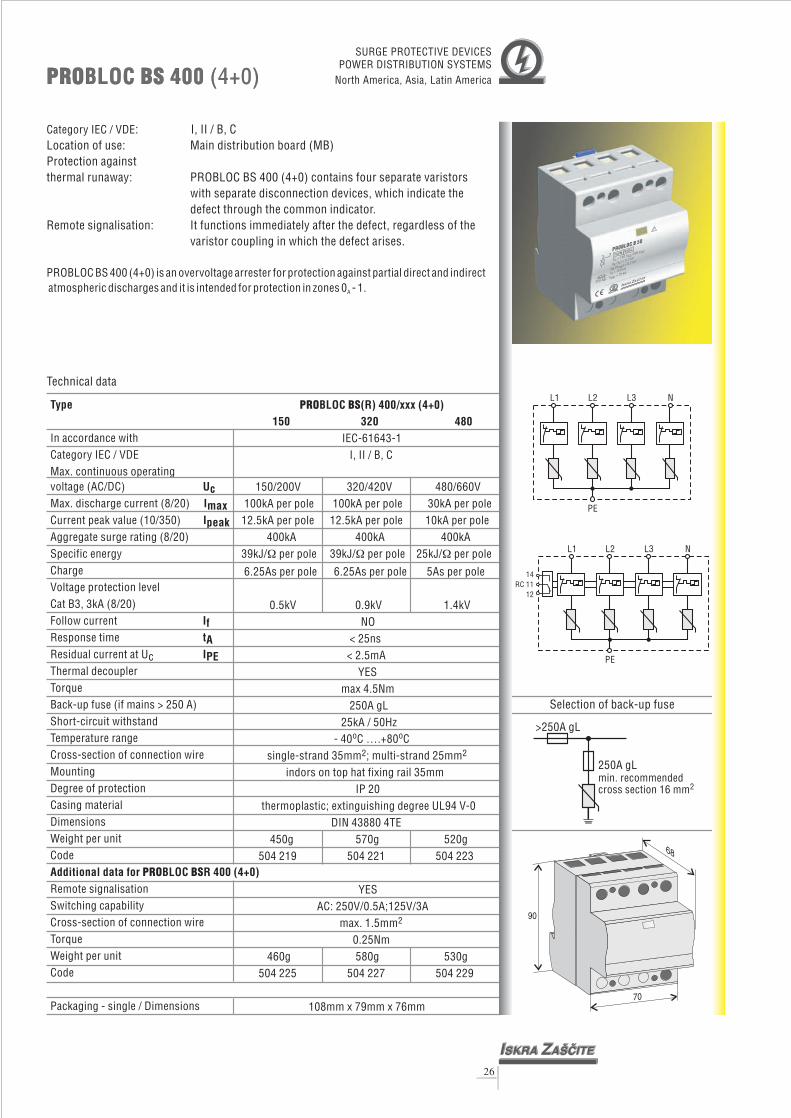
PRO BSBLOC (R) 400/xxx (4+0)150 320 480
IEC-61643-1I, II / B, C
150/200V 320/420V 480/660V
0.5kV 0.9kV 1.4kVNO
< 25ns< 2.5mA
YESmax 4.5Nm
250A gL25kA / 50Hz
100kA per pole 100kA per pole 30kA per pole12.5kA per pole 12.5kA per pole 10kA per pole
400kA 400kA 400kA39kJ/ per pole 39kJ/ per pole 25kJ/ per pole
6.25As per pole
� � �
6.25As per pole 5As per pole
- 40 C ….+80 C
indors on top hat fixing rail 35mmIP 20
thermoplastic; extinguishing degreeDIN 43880 4TE
o o
single-strand 35mm ; multi-strand 25mm
UL94 V-0
YESAC: 250V/0.5A;125V/3A
max. 1.5mm0.25Nm
2 2
2
450g 570g 520g504 219 504 221 504 223
460g 580g 530g504 225 504 227 504 229
108mm x 79mm x 76mm
Type
UcImax
In accordance withCategory IEC / VDEMax. continuous operating
(AC/DC)Max. discharge current (8/20)
Temperature rangeCross-section of connection wireMountingDegree of protectionCasing materialDimensions
Code
voltage
Current peak value (10/350)Aggregate surge rating (8/20)Specific energyChargeVoltage protection levelCat B3, 3kA (8/20)Follow currentResponse timeResidual current at UcThermal decouplerTorqueBack-up fuse (if mains > 250 A)Short-circuit withstand
Weight per unit
Remote signalisationSwitching capabilityCross-section of connection wireTorqueWeight per unitCode
Packaging - single / Dimensions
Ipeak
IftAIPE
Additional data for BLOC R 400 (4+0)PRO BS
PRO BSBLOC 400 (4+0)PRO BSBLOC 400 (4+0)
26
Technical data
Category IEC / VDE
PROBLOC BS 400 (4+0) is an overvoltage arrester for protection against partial direct and indirectatmospheric discharges and it is intended for protection in zones 0 - 1.
: I, II / B, CLocation of use: Main distribution board (MB)Protection againstthermal runaway: PROBLOC BS 400 (4+0) contains four
Remote signalisation:
A
separate varistorswith separate disconnection devices, which indicate thedefect through the common indicator.
varistor coupling in which the defect arises.It functions immediately after the defect, regardless of the
L2
L2
L3
L3
N
N
L1
L1
PE
PE
>250A gL
250A gLmin. recommendedcross section 16 mm2
Selection of back-up fuse
14RC 11
12
70
68
90
SURGE PROTECTIVE DEVICESPOWER DISTRIBUTION SYSTEMS
North America, Asia, Latin America

Type
Uc
In accordance withCategory IEC / VDEMax. permitted operating
(AC/DC)
Temperature rangeCross-section of connection wireMountingDegree of protectionCasing materialDimensions
Code
voltageMax. discharge current (8/20)Current peak value (10/350)Aggregate surge rating (8/20)Specific energyChargeVoltage protection levelCat B3, 3kA (8/20)Follow currentResponse timeResidual current at UcThermal decouplerTorqueBack-up fuse (if mains > 250 A)Short-circuit withstand
Weight per unit
Remote signalisationSwitching capabilityCross-section of connection wireTorqueWeight per unitCode
Packaging - single / Dimensions
ImaxIpeak
IftAIPE
Additional data for BLOCPRO BSR 400 (3+1)
L1
L1
L2
L2
L3
L3
N
N
PE
PE
14RC 11
12
87.5
90
68
Category IEC / VDE
PROBLOC BS 400 (3+1) is an overvoltage arrester for protection against partial direct andindirect atmospheric discharges and it is intended for protection in zones 0 - 1.
: I, II / B,C
Protection againstthermal runaway: PROBLOC BS 400 (3+1) contains three
Remote signalisation:
Location of use: Main distribution board (MB)
A
varistors withdisconnection devices, which indicate the defect through thecommon indicator.It functions immediately after the defect, regardless of thevaristor coupling in which the defect arises.
PRO BSBLOC 400 (3+1)PRO BSBLOC 400 (3+1)
565g 655g 630g504 231 504 233 504 235
575g 665g 640g504 237 504 239 504 241
YESAC: 250V/0.5A; 125V / 3A
max. 1.5mm0.25Nm
2
PRO BSBLOC (R) 400/xxx (3+1)150 320 480
IEC-61643-1I, II / B, C
150/200V 320/420V 480/660V
12.5kA 10kA400kA 400kA 400kA
0.5kV 0.9kV 1.4kV100ARMS< 100ns
/YES
max 4.5Nm250A gL
25kA/50Hz- 40 C ….+80 C
indors on top hat fixing rail 35mmIP 20
thermoplastic; extinguishing degree UL 94 V-0DIN 43880 5TE
100kA 100kA 100kA12.5kA
39kJ/ 39kJ/ 25kJ/
6.25As 6.25As 5As
single-strand 35mm ; multi-strand 25mm
� � �
o o
2 2
Technical data
27
>250A gL
250A gLmin. recommendedcross section 16 mm2
Selection of back-up fuse
SURGE PROTECTIVE DEVICESPOWER DISTRIBUTION SYSTEMS
North America, Asia, Latin America
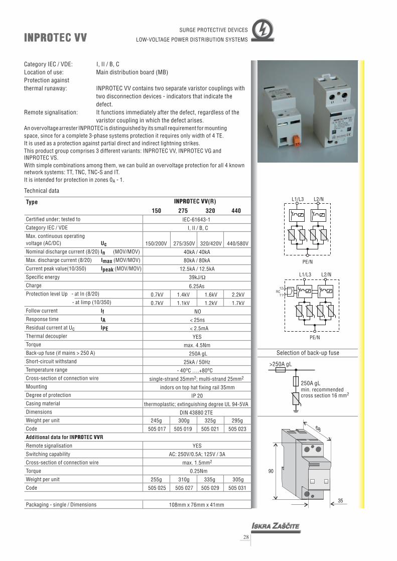
INPRO VVTECINPRO VVTEC
28
Category IEC / VDE: I, II / B, C
Protection againstthermal runaway:
Remote signalisation:
Location of use: Main distribution board (MB)
An overvoltage arrester INPROTEC is distinguished by its small requirement for mountingspace, since for a complete 3-phase systems protection it requires only width of 4 TE.It is used as a protection against partial direct and indirect lightning strikes.This product group comprises 3 different variants: INPROTEC VV, INPROTEC VG andINPROTEC VS.With simple combinations among them, we can build an overvoltage protection for all 4 knownnetwork systems: TT, TNC, TNC-S and IT.It is intended for protection in zones 0 - 1.A
INPROTEC VV contains two separate varistor couplings withtwo disconnection devices - indicators that indicate thedefect.It functions immediately after the defect, regardless of thevaristor coupling in which the defect arises.
>250A gL
250A gLmin. recommendedcross section 16 mm2
Selection of back-up fuse
35
68
90
SURGE PROTECTIVE DEVICES
LOW-VOLTAGE POWER DISTRIBUTION SYSTEMS
L1/L3
PE/N
PE/N
L1/L3
L2/N
L2/N
12RC
11
245g 300g 325g 295g
505 017 505 019 505 021 505 023
255g 310g 335g 305g
505 025 505 027 505 029 505 031
108mm x 76mm x 41mm
YES
AC: 250V/0.5A; 125V / 3A
max. 1.5mm
0.25Nm
2
INPRO VVTEC (R)
150 275 320 440IEC-61643-1
I, II / B, C
150/200V 275/350V 320/420V 440/580V
12.5kA /
0.7kV 1.4kV 1.6kV 2.2kV
0.7kV 1.1kV 1.2kV 1.7kV
NO
< 25ns
< 2.5mA
YES
max. 4.5Nm
250A gL
25kA / 50Hz
- 40 C ….+80 C
indors on top hat fixing rail 35mm
IP 20
thermoplastic; extinguishing degree UL 94-5VA
DIN 43880 2TE
40kA / 40kA
80kA / 80kA
12.5kA
39kJ/
6.25As
single-strand 35mm ; multi-strand 25mm
�
o o
2 2
Technical data
Type
Certified under; tested to
Category IEC / VDE
Max. continuous operating(AC/DC)
Nominal discharge current (8/20)
Max. discharge current (8/20)
Current peak value(10/350)
Protection level Up - at In (8/20)
- at Iimp (10/350)
Response time
Thermal decoupler
Back-up fuse (if mains > 250 A)
Short-circuit withstand
Temperature range
Cross-section of connection wire
Mounting
Degree of protection
Casing material
Dimensions
Code
voltage
(MOV/MOV)
(MOV/MOV)
(MOV/MOV)
Specific energy
Charge
Follow current
Residual current at Uc
Torque
Weight per unit
Remote signalisation
Switching capability
Cross-section of connection wire
Torque
Weight per unit
Code
Packaging - single / Dimensions
UcInImaxIpeak
tA
If
IPE
Additional data for IN TEC RPRO VV

INPRO VSTECINPRO VSTEC
29
Category IEC / VDE: I, II / B, CLocation of use: Main distribution board (MB)Protection againstthermal runaway:
Remote signalisation:
An overvoltage arrester INPROTEC is distinguished by its small requirement for mountingspace, since for a complete 3-phase systems protection it requires only width of 4 TE.It is used as a protection against partial direct and indirect lightning strikes.This product group comprises 3 different variants: INPROTEC VV, INPROTEC VG andINPROTEC VS.With simple combinations among them, we can build an overvoltage protection for all 4 knownnetwork systems: TT, TNC, TNC-S and IT.It is intended for protection in zones 0 - 1.A
INPROTEC VS contains varistor coupling withdisconnection device - indicator that indicates the defect.It functions immediately after the defect in the varistorcoupling.
>250A gL
250A gLmin. recommendedcross section 16 mm2
Selection of back-up fuse
35
68
90
SURGE PROTECTIVE DEVICES
LOW-VOLTAGE POWER DISTRIBUTION SYSTEMS
215g 225g 240g 225g
505 001 505 003 505 005 505 007
225g 235g 250g 235g
505 009 505 0211 505 013 505 015
108mm x 76mm x 41mm
YES
AC: 250V/0.5A; 125V / 3A
max. 1.5mm
0.25Nm
2
INPRO VSTEC (R)
150 275 320 440IEC-61643-1
I, II / B, C
150/200V 275/350V 320/420V 440/580V
12.5kA / -
0.7kV 1.4kV 1.6kV 2.2kV
0.7kV 1.1kV 1.2kV 1.7kV
NO
< 25ns
< 2.5mA
YES
max. 4.5Nm
250 A gL
25kA / 50Hz
- 40 C ….+80 C
indors on top hat fixing rail 35mm
IP 20
thermoplastic; extinguishing degree UL 94-5VA
DIN 43880 2TE
40kA / -
80kA / -
39kJ/
6.25As
single-strand 35mm ; multi-strand 25mm
�
o o
2 2
Technical data
Type
Certified under; tested to
voltage
(MOV/-)
(MOV/-)
(MOV/-)
Specific energy (MOV/-)
Charge (MOV/-)
Follow current
Residual current at Uc
Torque
Weight per unit
Remote signalisation
Switching capability
Cross-section of connection wire
Torque
Weight per unit
Code
Packaging - single / Dimensions
Category IEC / VDE
Max. continuous operating(AC/DC)
Nominal discharge current (8/20)
Max. discharge current (8/20)
Current peak value(10/350)
Protection level Up - at In (8/20)
- at Iimp (10/350)
Response time
Thermal decoupler
Back-up fuse (if mains > 250 A)
Short-circuit withstand
Temperature range
Cross-section of connection wire
Mounting
Degree of protection
Casing material
Dimensions
Code
UcInImaxIpeak
tA
If
IPE
Additional data for IN TEC RPRO VS
L3/L1
L3/L1
N
N
PEN/PE
PEN/PE
12RC
11

Category IEC / VDE: I, II / B,C
Protection againstthermal runaway:
Remote signalisation:
Location of use: Main distribution board (MB)
An overvoltage arrester INPROTEC is distinguished by its small requirement for mountingspace, since for a complete 3-phase systems protection it requires only width of 4 TE.It is used as a protection against partial direct and indirect lightning strikes.This product group comprises 3 different variants: INPROTEC VV, INPROTEC VG andINPROTEC VS.With simple combinations among them, we can build an overvoltage protection for all 4 knownnetwork systems: TT, TNC, TNC-S and IT.It is intended for protection in zones 0 - 1.A
INPROTEC VG contains varistor coupling withdisconnection device - indicator that indicates the defect.It functions immediately after the defect in the varistorcoupling.
INPRO VGTECINPRO VGTEC
230g 260g 270g 260g
505 033 505 035 505 037 505 039
YES
AC: 250V/0.5A; 125V / 3A
max. 1.5mm2
6.25As/50As
single-strand 35mm ; multi-strand 25mm
UL 94-5VA
0.7kV 1.4kV 1.6kV 2.2kV
0.7kV 1.1kV 1.2kV 1.7kV
1.2kV 1.2kV 1.2kV 1.2kV
NO / 100A
< 25ns / 100ns
< 2.5mA / -
YES / -
max. 4.5Nm
250A gL / -
25kA/50Hz / -
- 40 C ….+ 80 C
indors on top hat fixing rail 35mm
IP 20
thermoplastic; extinguishing degree
DIN 43880 2TE
RMS
o o
2 2
INPRO VGTEC (R)
150 275 320 440IEC-61643-1
I, II / B, C
150/200V 275/350V 320/420V 440/580V
12.5kA / 50kA
40kA / 40kA
80kA / 80kA
39kJ/ /2.5MJ/� �
Technical data
Type
In accordance with
Category IEC / VDE
Max. continuous operating(AC/DC)
Nominal discharge current (8/20)
Max. discharge current (8/20)
Current peak value (10/350)
Protection level Up - at In (8/20) - MOV
- at Iimp (10/350) - MOV
- at (1.2/50) - GDT
Response time
Thermal decoupler
Back-up fuse (if mains > 250 A)
Short-circuit withstand
Temperature range
Cross-section of connection wire
Mounting
Degree of protection
Casing material
Dimensions
Code
voltage
(MOV/GDT)
(MOV/GDT)
(MOV/GDT)
Specific energy (MOV/GDT)
Charge (MOV/GDT)
Follow current
(MOV/GDT)
Residual current at Uc
Torque
Weight per unit
Remote signalisation
Switching capability
Cross-section of connection wire
Torque
Weight per unit
Code
Packaging - single / Dimensions
UcInImaxIpeak
tA
If
IPE
Additional data for IN TEC RPRO VG
30
>250A gL
250A gLmin. recommendedcross section 16 mm2
Selection of back-up fuse
SURGE PROTECTIVE DEVICES
LOW-VOLTAGE POWER DISTRIBUTION SYSTEMS
L3/L1
L3/L1
PE
PE
N
N
12RC
11
35
68
900,25Nm
240g 270g 280g 270g
505 041 505 043 505 045 505 047
108mm x 76mm x 41mm

Type
UcInImaxIpeak
tA
In accordance withCategory IEC / VDEMax. continuous operating
(AC/DC)Nominal discharge current (8/20)Max. discharge current (8/20)Current peak value (10/350)Specific energyChargeProtection level Up - at In (8/20)
- at Iimp (10/350)Follow currentResponse time
Thermal decoupler
Back-up fuse (if mains > 160 A)Short-circuit withstandTemperature rangeCross-section of connection wireMountingDegree of protectionCasing materialDimensions
Code
voltage
Residual current at Uc
Torque
Weight per unit
Remote signalisationSwitching capabilityCross-section of connection wireTorqueWeight per unitCode
Packaging - single / Dimensions
I
I
Additional data for TEC R 15
f
PE
PRO B2S
PRO B2STEC 15PRO B2STEC 15
31
PRO B2STEC (R) 15/xxx150 275 320 440
IEC-61643-1I, II / B, C
150/200V 275/350V 320/420V 440/580V20kA 250kA 50kA 50kA 50kA15kA 15kA 15kA 12.5kA
0.7kV 1.2kV 1.4kV 2.0kV0.7kV 1.1kV 1.2kV 1.7kV
NO< 25ns
< 2.5mAYES
max. 3.5Nm160A gL
25kA / 50Hz- 40 C ….+80 C
single-strand 35mm ; multi-strand 25mmindors on top hat fixing rail 35mm
IP 20thermoplastic; extinguishing degree
DIN 43880 1TE
0kA 20kA 20kA
56kJ/ 56kJ/ 56kJ/ 39kJ/
7.5As 7.5As 7.5As 6.25As
UL 94-V0
YESAC: 250V/0.5A; 125V/3A
max. 1.5mm0.25Nm
108mm x 74mm x 24mm
o o
2 2
2
� � � �
130g 170g 180g 160g500 633 500 635 500 637 500 639
140g 180g 190g 170g500 641 500 643 500 645 500 647
Technical data
Category IEC / VDE: I, II / B, CLocation of use: It is installed in main distribution board (MB).Protection againstthermal runaway: disconnecting device, which optically signalises a varistor
failure.Remote signalisation: reacts immediately after a varistor failureModule replacement: YES! In case of failure we can replace only a module.
A base remains on a DIN strip.
PROTEC B2S 15 is intended for protection againstinduced surges. As a protective element a varistor is used. Therefore, also at this
module no following current (I ) is present.
partial direct and indirect atmosphericdischarges and
It is intended for protection in zones 0 -1.F
A
>160A gL
160A gLmin. recommendedcross section 16 mm2
Selection of back-up fuse
SURGE PROTECTIVE DEVICES
LOW-VOLTAGE POWER DISTRIBUTION SYSTEMS
L/N
L/N
PE
PE
141112
RC
68
4590
17.5
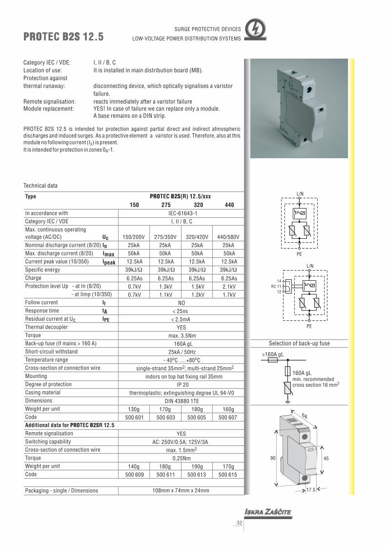
Type
UcInImaxIpeak
tA
In accordance withCategory IEC / VDEMax. continuous operating
(AC/DC)Nominal discharge current (8/20)Max. discharge current (8/20)Current peak value (10/350)Specific energyChargeProtection level Up - at In (8/20)
- at Iimp (10/350)Follow currentResponse time
Thermal decoupler
Back-up fuse (if mains > 160 A)Short-circuit withstandTemperature rangeCross-section of connection wireMountingDegree of protectionCasing materialDimensions
Code
voltage
Residual current at Uc
Torque
Weight per unit
Remote signalisationSwitching capabilityCross-section of connection wireTorqueWeight per unitCode
Packaging - single / Dimensions
I
I
Additional data for TEC R 12.5
f
PE
PRO B2S
PRO B2STEC 12.5PRO B2STEC 12.5
32
PRO B2STEC (R) 12.5/xxx150 275 320 440
IEC-61643-1I, II / B, C
150/200V 275/350V 320/420V 440/580V25kA 2550kA 50kA 50kA 50kA
12.5kA 12.5kA 12.5kA 12.5kA
0.7kV 1.3kV 1.5kV 2.1kV0.7kV 1.1kV 1.2kV 1.7kV
NO< 25ns
< 2.5mAYES
max. 3.5Nm160A gL
25kA / 50Hz- 40 C ….+80 C
single-strand 35mm ; multi-strand 25mmindors on top hat fixing rail 35mm
IP 20thermoplastic; extinguishing degree
DIN 43880 1TE
kA 25kA 25kA
39kJ/ 39kJ/ 39kJ/ 39kJ/
6.25As 6.25As 6.25As 6.25As
UL 94-V0
YESAC: 250V/0.5A; 125V/3A
max. 1.5mm0,25Nm
108mm x 74mm x 24mm
o o
2 2
2
� � � �
130g 170g 180g 160g500 601 500 603 500 605 500 607
140g 180g 190g 170g500 609 500 611 500 613 500 615
Technical data
Category IEC / VDE: I, II / B, CLocation of use: It is installed in main distribution board (MB).Protection againstthermal runaway: disconnecting device, which optically signalises a varistor
failure.Remote signalisation: reacts immediately after a varistor failureModule replacement: YES! In case of failure we can replace only a module.
A base remains on a DIN strip.
PROTEC B2S 12.5 is intended for protection againstinduced surges. As a protective element a varistor is used. Therefore, also at this
module no following current (I ) is present.
partial direct and indirect atmosphericdischarges and
It is intended for protection in zones 0 -1.F
A
>160A gL
160A gLmin. recommendedcross section 16 mm2
Selection of back-up fuse
SURGE PROTECTIVE DEVICES
LOW-VOLTAGE POWER DISTRIBUTION SYSTEMS
L/N
L/N
PE
PE
141112
RC
68
4590
17.5

PRO B2STEC 30 (2+0)PRO B2STEC 30 (2+0)
33
TNS Three-p Dimensions Weight per unit CodePROTEC B2S 30/150 (2+0) DIN 43880 2TE 240g 500 793
hase Network
PROTEC B2S 30/275 (2+0) DIN 43880 2TE 315g 500 795PROTEC B2S 30/320 (2+0) DIN 43880 2TE 330g 500 797PROTEC B2S 30/440 (2+0) DIN 43880 2TE 295g 500 799PROTEC B2SR 30/150 (2+0) DIN 43880 2TE 250g 500 801PROTEC B2SR 30/275 (2+0) DIN 43880 2TE 325g 500 803PROTEC B2SR 30/320 (2+0) DIN 43880 2TE 340g 500 805PROTEC B2SR 30/440 (2+0) DIN 43880 2TE 305g 500 807
SURGE PROTECTIVE DEVICESLOW-VOLTAGE
POWER DISTRIBUTION SYSTEMS
TN-S Network (2+0)
EBB
With Remote Control2 x PROTEC B2SR
N N
Without Remote Control2 x PROTEC B2S
PE PE
L L
RemoteControl
PRO B2STEC PRO B2STEC
N
N
L
L
PE
PE
14RC11
12
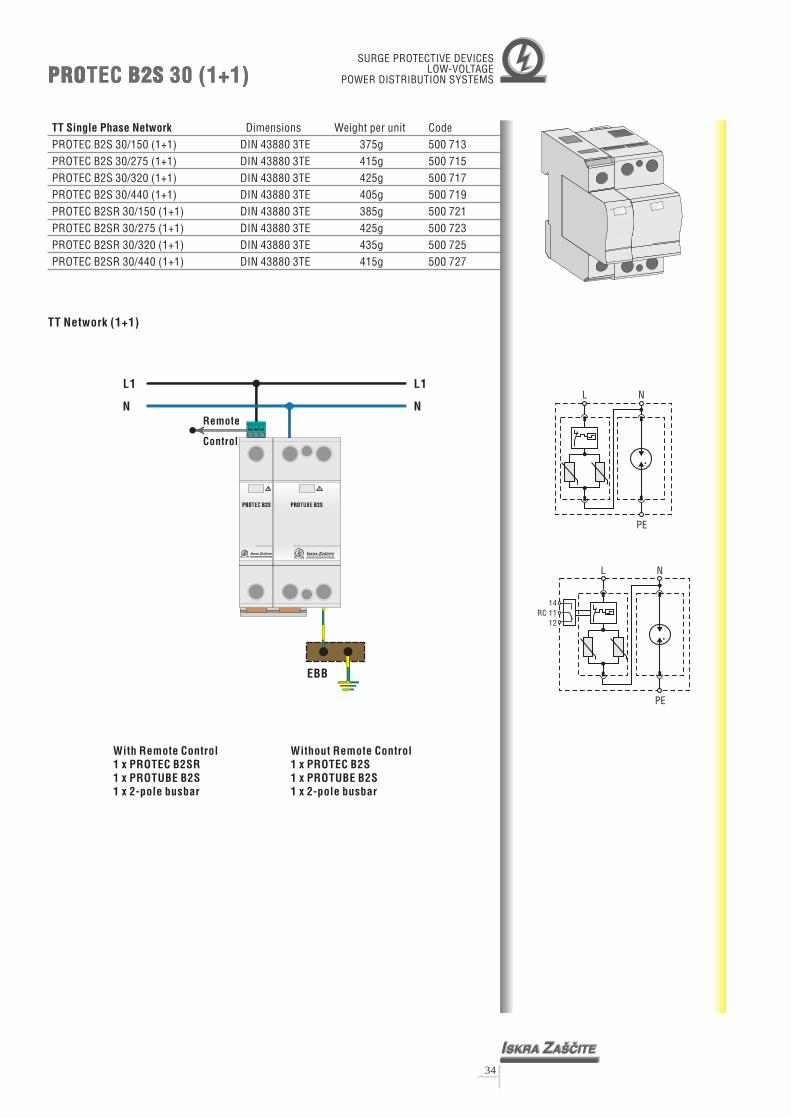
PRO B2STEC 30 (1+1)PRO B2STEC 30 (1+1)
34
TT Dimensions Weight per unit CodePROTEC B2S 30/150 (1+1) DIN 43880 3TE 375g 500 713
Single Phase Network
PROTEC B2S 30/275 (1+1) DIN 43880 3TE 415g 500 715PROTEC B2S 30/320 (1+1) DIN 43880 3TE 425g 500 717PROTEC B2S 30/440 (1+1) DIN 43880 3TE 405g 500 719PROTEC B2SR 30/150 (1+1) DIN 43880 3TE 385g 500 721PROTEC B2SR 30/275 (1+1) DIN 43880 3TE 425g 500 723PROTEC B2SR 30/320 (1+1) DIN 43880 3TE 435g 500 725PROTEC B2SR 30/440 (1+1) DIN 43880 3TE 415g 500 727
N
N
L
L
PE
PE
14RC 11
12
SURGE PROTECTIVE DEVICESLOW-VOLTAGE
POWER DISTRIBUTION SYSTEMS
TT Network (1+1)
With Remote Control1 x PROTEC B2SR1 x PROTUBE B2S1 x 2-pole busbar
Without Remote Control1 x PROTEC B2S1 x PROTUBE B2S1 x 2-pole busbar
Remote
Control
N N
L1 L1
EBB
PRO B2STUBEPRO B2STEC

PRO B2STEC 45 (3+0)PRO B2STEC 45 (3+0)
35
TNC Three-p Dimensions Weight per unit CodePROTEC B2S 45/150 (3+0) DIN 43880 3TE 350g 500 729
hase Network
PROTEC B2S 45/275 (3+0) DIN 43880 3TE 460g 500 731PROTEC B2S 45/320 (3+0) DIN 43880 3TE 480g 500 733PROTEC B2S 45/440 (3+0) DIN 43880 3TE 430g 500 735PROTEC B2SR 45/150 (3+0) DIN 43880 3TE 360g 500 737PROTEC B2SR 45/275 (3+0) DIN 43880 3TE 470g 500 739PROTEC B2SR 45/320 (3+0) DIN 43880 3TE 490g 500 741PROTEC B2SR 45/440 (3+0) DIN 43880 3TE 440g 500 743
SURGE PROTECTIVE DEVICESLOW-VOLTAGE
POWER DISTRIBUTION SYSTEMS
TN-C Network (3+0)
With Remote Control3 x PROTEC B2SR
Without Remote Control3 x PROTEC B2S
L3
L3
L2
L2
L1
L1
PEN
PEN
14RC 11
12
L3 L3
L2 L2
L1 L1
PEN PEN
EBB
RemoteControl
PRO B2STEC PRO B2STEC PRO B2STEC

PRO B2STEC 60 (4+0)PRO B2STEC 60 (4+0)
36
TNS Three-p Dimensions Weight per unit CodePROTEC B2S 60/150 (4+0) DIN 43880 4TE 460g 500 745
hase Network
PROTEC B2S 60/275 (4+0) DIN 43880 4TE 605g 500 747PROTEC B2S 60/320 (4+0) DIN 43880 4TE 630g 500 749PROTEC B2S 60/440 (4+0) DIN 43880 4TE 565g 500 751PROTEC B2SR 60/150 (4+0) DIN 43880 4TE 470g 500 753PROTEC B2SR 60/275 (4+0) DIN 43880 4TE 615g 500 755PROTEC B2SR 60/320 (4+0) DIN 43880 4TE 640g 500 757PROTEC B2SR 60/440 (4+0) DIN 43880 4TE 575g 500 759
SURGE PROTECTIVE DEVICESLOW-VOLTAGE
POWER DISTRIBUTION SYSTEMS
TN-S Network (4+0)
L3 NL2L1
PE
With Remote Control4 x PROTEC B2SR
Without Remote Control4 x PROTEC B2S
L3 NL2L1
PE
14RC 11
12
EBB
N N
PE PE
L3 L3
L2 L2
L1 L1
RemoteControl
PRO B2STEC PRO B2STEC PRO B2STEC PRO B2STEC

PRO B2STEC 60 (3+1)PRO B2STEC 60 (3+1)
37
TT Three-p Dimensions Weight per unit CodePROTEC B2S 60/150 (3+1) DIN 43880 5TE 585g 500 761
hase Network
PROTEC B2S 60/275 (3+1) DIN 43880 5TE 695g 500 763PROTEC B2S 60/320 (3+1) DIN 43880 5TE 715g 500 765PROTEC B2S 60/440 (3+1) DIN 43880 5TE 665g 500 767PROTEC B2SR 60/150 (3+1) DIN 43880 5TE 595g 500 769PROTEC B2SR 60/275 (3+1) DIN 43880 5TE 705g 500 771PROTEC B2SR 60/320 (3+1) DIN 43880 5TE 725g 500 773PROTEC B2SR 60/440 (3+1) DIN 43880 5TE 675g 500 775
SURGE PROTECTIVE DEVICESLOW-VOLTAGE
POWER DISTRIBUTION SYSTEMS
TT Network (3+1)
NL3L2L1
PE
With Remote Control3 x PROTEC B2SR1 x PROTUBE B2S1 x 2-pole busbar
Without Remote Control3 x PROTEC B2S1 x PROTUBE B2S1 x 2-pole busbar
NL3L2L1
PE
14RC 11
12
N N
L3 L3
L2 L2
L1 L1
EBB
RemoteControl
PRO B2STUBEPRO B2STECPRO B2STEC PRO B2STEC

PRO B2STEC 25 (2+0)PRO B2STEC 25 (2+0)
38
TNS Three-p Dimensions Weight per unit CodePROTEC B2S 25/150 (2+0) DIN 43880 2TE 240g 500 777
hase Network
PROTEC B2S 25/275 (2+0) DIN 43880 2TE 315g 500 779PROTEC B2S 25/320 (2+0) DIN 43880 2TE 330g 500 781PROTEC B2S 25/440 (2+0) DIN 43880 2TE 295g 500 783PROTEC B2SR 25/150 (2+0) DIN 43880 2TE 250g 500 785PROTEC B2SR 25/275 (2+0) DIN 43880 2TE 325g 500 787PROTEC B2SR 25/320 (2+0) DIN 43880 2TE 340g 500 789PROTEC B2SR 25/440 (2+0) DIN 43880 2TE 305g 500 791
SURGE PROTECTIVE DEVICESLOW-VOLTAGE
POWER DISTRIBUTION SYSTEMS
TN-S Network (2+0)
EBB
With Remote Control2 x PROTEC B2SR
N N
Without Remote Control2 x PROTEC B2S
PE PE
L L
RemoteControl
PRO B2STEC PRO B2STEC
N
N
L
L
PE
PE
14RC11
12

PRO B2STEC 25 (1+1)PRO B2STEC 25 (1+1)
39
TT Dimensions Weight per unit CodePROTEC B2S 25/150 (1+1) DIN 43880 3TE 375g 500 649
Single Phase Network
PROTEC B2S 25/275 (1+1) DIN 43880 3TE 415g 500 651PROTEC B2S 25/320 (1+1) DIN 43880 3TE 425g 500 653PROTEC B2S 25/440 (1+1) DIN 43880 3TE 405g 500 655PROTEC B2SR 25/150 (1+1) DIN 43880 3TE 385g 500 657PROTEC B2SR 25/275 (1+1) DIN 43880 3TE 425g 500 659PROTEC B2SR 25/320 (1+1) DIN 43880 3TE 435g 500 661PROTEC B2SR 25/440 (1+1) DIN 43880 3TE 415g 500 663
SURGE PROTECTIVE DEVICESLOW-VOLTAGE
POWER DISTRIBUTION SYSTEMS
TT Network (1+1)
With Remote Control1 x PROTEC B2SR1 x PROTUBE B2S1 x 2-pole busbar
Without Remote Control1 x PROTEC B2S1 x PROTUBE B2S1 x 2-pole busbar
N
N
L
L
PE
PE
14RC 11
12
Remote
Control
N N
L1 L1
EBB
PRO B2STUBEPRO B2STEC

PRO B2STEC 37.5 (3+0)PRO B2STEC 37.5 (3+0)
40
TNC Three-p Dimensions Weight per unit CodePROTEC B2S 37.5/150 (3+0) DIN 43880 3TE 350g 500 665
hase Network
PROTEC B2S 37.5/275 (3+0) DIN 43880 3TE 460g 500 667PROTEC B2S 37.5/320 (3+0) DIN 43880 3TE 480g 500 669PROTEC B2S 37.5/440 (3+0) DIN 43880 3TE 430g 500 671PROTEC B2SR 37.5/150 (3+0) DIN 43880 3TE 360g 500 673PROTEC B2SR 37.5/275 (3+0) DIN 43880 3TE 470g 500 675PROTEC B2SR 37.5/320 (3+0) DIN 43880 3TE 490g 500 677PROTEC B2SR 37.5/440 (3+0) DIN 43880 3TE 440g 500 679
SURGE PROTECTIVE DEVICESLOW-VOLTAGE
POWER DISTRIBUTION SYSTEMS
TN-C Network (3+0)
With Remote Control3 x PROTEC B2SR
Without Remote Control3 x PROTEC B2S
L3
L3
L2
L2
L1
L1
PEN
PEN
14RC 11
12
L3 L3
L2 L2
L1 L1
PEN PEN
EBB
RemoteControl
PRO B2STEC PRO B2STEC PRO B2STEC

PRO B2STEC 50 (4+0)PRO B2STEC 50 (4+0)
41
TNS Three-p Dimensions Weight per unit CodePROTEC B2S 50/150 (4+0) DIN 43880 4TE 460g 500 681
hase Network
PROTEC B2S 50/275 (4+0) DIN 43880 4TE 605g 500 683PROTEC B2S 50/320 (4+0) DIN 43880 4TE 630g 500 685PROTEC B2S 50/440 (4+0) DIN 43880 4TE 565g 500 687PROTEC B2SR 50/150 (4+0) DIN 43880 4TE 490g 500 689PROTEC B2SR 50/275 (4+0) DIN 43880 4TE 615g 500 691PROTEC B2SR 50/320 (4+0) DIN 43880 4TE 640g 500 693PROTEC B2SR 50/440 (4+0) DIN 43880 4TE 575g 500 695
SURGE PROTECTIVE DEVICESLOW-VOLTAGE
POWER DISTRIBUTION SYSTEMS
TN-S Network (4+0)
With Remote Control4 x PROTEC B2SR
Without Remote Control4 x PROTEC B2S
L3 NL2L1
PE
L3 NL2L1
PE
14RC 11
12
EBB
N N
PE PE
L3 L3
L2 L2
L1 L1
RemoteControl
PRO B2STEC PRO B2STEC PRO B2STEC PRO B2STEC

PRO B2STEC 50 (3+1)PRO B2STEC 50 (3+1)
42
TT Three-p Dimensions Weight per unit CodePROTEC B2S 50/150 (3+1) DIN 43880 5TE 585g 500 697
hase Network
PROTEC B2S 50/275 (3+1) DIN 43880 5TE 695g 500 699PROTEC B2S 50/320 (3+1) DIN 43880 5TE 715g 500 701PROTEC B2S 50/440 (3+1) DIN 43880 5TE 665g 500 703PROTEC B2SR 50/150 (3+1) DIN 43880 5TE 595g 500 705PROTEC B2SR 50/275 (3+1) DIN 43880 5TE 705g 500 707PROTEC B2SR 50/320 (3+1) DIN 43880 5TE 725g 500 709PROTEC B2SR 50/440 (3+1) DIN 43880 5TE 675g 500 711
SURGE PROTECTIVE DEVICESLOW-VOLTAGE
POWER DISTRIBUTION SYSTEMS
TT Network (3+1)
With Remote Control3 x PROTEC B2SR1 x PROTUBE B2S1 x 2-pole busbar
Without Remote Control3 x PROTEC B2S1 x PROTUBE B2S1 x 2-pole busbar
NL3L2L1
PE
NL3L2L1
PE
14RC 11
12
N N
L3 L3
L2 L2
L1 L1
EBB
RemoteControl
PRO B2STUBEPRO B2STECPRO B2STEC PRO B2STEC

Type
UcInImaxIpeak
tA
In accordance with
voltage
Residual current at Uc
Torque
Weight per unit
Remote signalisationSwitching capabilityCross-section of connection wireTorqueWeight per unitCode
Packaging - single / Dimensions
Category IEC / VDEMax. continuous operating
(AC/DC)Nominal discharge current (8/20)Max. discharge current (8/20)Current peak value (10/350)Specific energyChargeProtection level Up - at In (8/20)
- at Iimp (10/350)Follow currentResponse time
Thermal decoupler
Back-up fuse (if mains > 160 A)Short-circuit withstandTemperature rangeCross-section of connection wireMountingDegree of protectionCasing materialDimensions
Code
I
I
Additional data for TEC R 25
f
PE
PRO B2N
PRO B2NTEC 25PRO B2NTEC 25
43
PRO B2NTEC (R) 25/xxx150 275 320 440
IEC-61643-1I, II / B, C
150/200V 275/350V 320/420V 440/580V40kA 4080kA 80kA 80kA 80kA25kA 25kA 25kA 25kA
0.8kV 1.5kV 1.6kV 2.0kV0.7kV 1.2kV 1.3kV 1.9kV
NO< 25ns< 2.5mA
YESmax. 4.5Nm
160A gL25kA / 50Hz
- 40 C ….+80 Csingle-strand 35mm ; multi-strand 25mm
indors on top hat fixing rail 35mmIP 20
thermoplastic; extinguishing degreeDIN 43880 1TE
175g 230g 235g 215g
kA 40kA 40kA
156kJ/ 156kJ/ 156kJ/ 156kJ/
12.5As 12.5As 12.5As 12.5As
UL 94 V-0
YESAC: 250V/0.5A; 125V/3A
max. 1.5mm0,25Nm
185g 240g 245g 225g
108mm x 74mm x 24mm
o o
2 2
2
� � � �
507 541 507 543 507 545 507 547
507 549 507 551 507 553 507 555
Technical data
Category IEC / VDE: I, II / B, CLocation of use: It is installed in main distribution board (MB) or in the sub-
distribution panel (SB)or as close as possible to a protecteddevice.
Protection againstthermal runaway: disconnecting device, which optically signalises a varistor
failure.Remote signalisation: reacts immediately after a varistor failure
PROTEC B2N 25 is intended for protection againstinduced surges. As a protective element a varistor is used. Therefore, also at this
module no following current (IF) is present.
partial direct and indirect atmosphericdischarges and
It is intended for protection in zones 0 -1.A
>160A gL
160A gLmin. recommendedcross section 16 mm2
Selection of back-up fuse
SURGE PROTECTIVE DEVICES
LOW-VOLTAGE POWER DISTRIBUTION SYSTEMS
66
4590
17.5
PE
PE
L/N
L/N
141112
RC

Type
UcInImaxIpeak
tA
In accordance with
voltage
Residual current at Uc
Torque
Weight per unit
Remote signalisationSwitching capabilityCross-section of connection wireTorqueWeight per unitCode
Packaging - single / Dimensions
Category IEC / VDEMax. continuous operating
(AC/DC)Nominal discharge current (8/20)Max. discharge current (8/20)Current peak value (10/350)Specific energyChargeProtection level Up - at In (8/20)
- at Iimp (10/350)Follow currentResponse time
Thermal decoupler
Back-up fuse (if mains > 160 A)Short-circuit withstandTemperature rangeCross-section of connection wireMountingDegree of protectionCasing materialDimensions
Code
I
I
Additional data for TEC R 12.5
f
PE
PRO B2N
PRO B2NTEC 12.5PRO B2NTEC 12.5
44
PRO B2NTEC (R) 12.5/xxx150 275 320 440
IEC-61643-1I, II / B, C
150/200V 275/350V 320/420V 440/580V20kA 2050kA 50kA 50kA 50kA
12.5kA 12.5kA 12.5kA 12.5kA
0.8kV 1.5kV 1.6kV 2.0kV0.7kV 1.2kV 1.3kV 1.9kV
NO< 25ns< 2.5mA
YESmax. 4.5Nm
160A gL25kA / 50Hz
- 40 C ….+80 Csingle-strand 35mm ; multi-strand 25mm
indors on top hat fixing rail 35mmIP 20
thermoplastic; extinguishing degreeDIN 43880 1TE
135g 150g 155g 145g507 501 507 503 507 505 507 507
kA 20kA 20kA
39kJ/ 39kJ/ 39kJ/ 39kJ/
6.25As 6.25As 6.25As 6.25As
UL 94 V-0
YESAC: 250V/0.5A; 125V/3A
max. 1.5mm0,25Nm
145g 160g 165g 155g507 509 507 511 507 513 507 515
108mm x 74mm x 24mm
� � � �
o o
2 2
2
Technical data
Category IEC / VDE: I, II / B, CLocation of use: It is installed in main distribution board (MB).Protection againstthermal runaway: disconnecting device, which optically signalises a varistor
failure.Remote signalisation: reacts immediately after a varistor failure
PROTEC B2N 12.5 is intended for protection againstinduced surges. As a protective element a varistor is used. Therefore, also at this
module no following current (IF) is present.
partial direct and indirect atmosphericdischarges and
It is intended for protection in zones 0 -1.A
>160A gL
160A gLmin. recommendedcross section 16 mm2
Selection of back-up fuse
SURGE PROTECTIVE DEVICES
LOW-VOLTAGE POWER DISTRIBUTION SYSTEMS
66
4590
17.5
PE
PE
L/N
L/N
141112
RC

Type
UcInImaxIpeak
tA
In accordance withCategory IEC / VDEMax. continuous operating
(AC/DC)Nominal discharge current (8/20)Max. discharge current (8/20)Current peak value (10/350)Specific energyChargeProtection level Up - at In (8/20)
- at Iimp (10/350)Follow currentResponse time
Thermal decoupler
Back-up fuse (if mains > 160 A)Short-circuit withstandTemperature rangeCross-section of connection wireMountingDegree of protectionCasing materialDimensions
Code
voltage
Residual current at Uc
Torque
Weight per unit
Remote signalisationSwitching capabilityCross-section of connection wireTorqueWeight per unitCode
Packaging - single / Dimensions
I
I
Additional data for TEC R 8
f
PE
PRO B2N
PRO B2NTEC 8PRO B2NTEC 8
45
PRO B2NTEC (R) 8/xxx150 275 320 440
IEC-61643-1I, II / B, C
150/200V 275/350V 320/420V 440/580V25kA 2550kA 50kA 50kA 50kA8kA 8kA 8kA 8kA
0.7kV 1.3kV 1.5kV 2.1kV0.7kV 1.1kV 1.2kV 1.7kV
NO< 25ns< 2.5mA
YESmax. 4.5Nm
160A gL25kA / 50Hz
- 40 C ….+80 Csingle-strand 35mm ; multi-strand 25mm
indors on top hat fixing rail 35mmIP 20
thermoplastic; extinguishing degreeDIN 43880 1TE
135g 150g 155g 145g507 519 507 521 507 523 507 525
kA 25kA 25kA
16kJ/ 16kJ/ 16kJ/ 16kJ/
4As 4As 4As 4As
UL 94 V-0
YESAC: 250V/0.5A; 125V/3A
max. 1.5mm0,25Nm
145g 160g 165g 155g507 527 507 529 507 531 507 533
108mm x 74mm x 24mm
� � � �
o o
2 2
2
Technical data
Category IEC / VDE: I, II / B, CLocation of use: It is installed in main distribution board (MB).Protection againstthermal runaway: disconnecting device, which optically signalises varistor
failure.Remote signalisation: reacts immediately after a varistor failure
PROTEC B2N 8 is intended for protection againstinduced surges. As a protective element a varistor is used. Therefore, also at this
module no following current (IF) is present.
partial direct and indirect atmosphericdischarges and
It is intended for protection in zones 0 -1.A
>160A gL
160A gLmin. recommendedcross section 16 mm2
Selection of back-up fuse
SURGE PROTECTIVE DEVICES
LOW-VOLTAGE POWER DISTRIBUTION SYSTEMS
66
4590
17.5
PE
PE
L/N
L/N
141112
RC

PV PRO BSTEC (R) 12,5/xxx100 550 1000
IEC-61643-1I, II / B, C
100V 550V 1000V40kA 480kA 80kA 80kA
12.
6.25As 6.20.5kV 1.8kV 2.2kV0.4kV 1.6kV 1.9kV
NO< 25ns
< 2.5mAYES
max. 4.5Nm250A gL
25kA / 50Hz- 40 C ….+80 C
single-strand 35mm ; multi-strand 25mmindors on top hat fixing rail 35mm
IP 20thermoplastic; extinguishing degree
2TE 3TE 4TE225g 400g 500g
501 501 501 507 501 541
0kA 40kA
5kA 12.5kA 12.5kA
5As 6.25As
UL 94 V-0
YESAC: 250V/0.5A;125V / 3A
max. 1.5mm0,25Nm
230g 410g 510g501 511 501 517 501 545
o o
2 2
2
39kJ/� 39kJ/ 39kJ/� �
Type
UcInImaxIpeak
tA
In accordance withCategory IEC / VDEMax. continuous operating
(DC)Nominal discharge current (8/20)Max. discharge current (8/20)Current peak value (10/350)Specific energyChargeProtection level Up - at In (8/20)
- at Iimp (10/350)Follow currentResponse timeResidual current atThermal decoupler
Back-up fuse (if mains > 250 A)Short-circuit withstandTemperature rangeCross-section of connection wireMountingDegree of protectionCasing materialDimensions DIN 43880
Code
voltage
Uc
Torque
Weight per unit
Remote signalisationSwitching capabilityCross-section of connection wireTorqueWeight per unitCode
Packaging - single / Dimensions
I
I
Additional data for PV TEC R 12.5
f
PE
PRO BS
PV PRO BSTEC 12.5PV PRO BSTEC 12.5
46
Technical data
Category IEC / VDE
PV PROTEC BS 12.5 is an overvoltage arrester for protection against partial direct and indirectatmospheric discharges and it is intended for protection in zones 0 - 1.
: I, II / B, CLocation of use: Photovoltaic systems - PV, module side.Protection againstthermal runaway: PV PROTEC BS 12.5 contains
Remote signalisation:
A
two separate varistors withdifferential protection and separate disconnection devices,which indicate the defect through a common indicator.It functions immediately after the defect, regardless of thevaristor coupling in which the defect arises.
+
+
-
-
PE
PE
>250A gL
250A gLmin. recommendedcross section 16 mm2
Selection of back-up fuse
SURGE PROTECTIVE DEVICES
LOW-VOLTAGE POWER DISTRIBUTION SYSTEMS
141112
RC

14RC 11
12
14RC 11
12
Type
UcInImax
tA
In accordance withCategory IEC / VDEMax. continuous operating
(DC)Nominal discharge current (8/20)Max. discharge current (8/20)
Protection level Up - at In (8/20)
Follow currentResponse time
Thermal decoupler
Back-up fuse (if mains > 125 A)Short-circuit withstandTemperature rangeCross-section of connection wireMountingDegree of protectionCasing materialDimensions DIN 43880
Code
voltage
Residual current at Uc
Torque
Weight per unit
Remote signalisationSwitching capabilityCross-section of connection wireTorqueWeight per unitCode
Packaging - single / Dimensions
I
I
Additional data for PV TEC R 40
f
PE
PRO C
Current peak value (10/350)Specific energyCharge
- at Iimp (10/350)
Ipeak
PV PRO CTEC 40PV PRO CTEC 40
47
PV PRO CTEC (R) 40/xxx100 550 1000
IEC-61643-1II / C
. 100V 550V 1000V10kA 20kA 240kA 40kA
///
0.3kV 2.2kV 3.0kV
NO< 25ns
< 1.5mAYES
max. 4.5Nm125A gL
25kA / 50Hz- 40 C ….+80 C
single-strand 35mm ; multi-strand 25mmindors on top hat fixing rail 35mm
IP 20thermoplastic; extinguishing degree
2TE 2TE 3TE200g 255g 365g
501 521 501 527 501 543
0kA40kA
/
UL 94 V-0
YESAC: 250V/0.5A; 125V/3A
max. 1.5mm0,25Nm
210g 265g 375g501 531 501 537 501 547
o o
2 2
2
Technical data
Category IEC / VDE: II / CLocation of use: Photovoltaic systems - PV module sideProtection againstthermal runaway: disconnecting device, which optically signalizes a varistor
failure.Remote signalisation: reacts immediately after a varistor failureModule replacement: YES! In case of failure we can replace only a module.
A base remains on a DIN strip.
PV PROTEC C 40 is intended for protection against indirect lightning strikes. As a protectiveelement a varistor is used. Therefore, also at this module no following current (I ) is present.It is intended for protection in zones 1-2.
FBut it has to be co-ordinated with lightning arresters.
+
+
-
-
PE
PE
>125A gL
125A gLmin. recommendedcross section 6 mm2
Selection of back-up fuse
SURGE PROTECTIVE DEVICES
LOW-VOLTAGE POWER DISTRIBUTION SYSTEMS
+
+
-
-
PE
PE
PV PRO CPV PRO C
TEC (R) 40/100TEC (R) 40/550
PV PRO CTEC (R)40/1000

Type
UcInImax
tA
In accordance withCategory IEC / VDEMax. continuous operating
(AC/DC)Nominal discharge current (8/20)Max. discharge current (8/20)
Protection level Up - at In (8/20)
Follow currentResponse time
Thermal decoupler
Back-up fuse (if mains > 125 A)Short-circuit withstandTemperature rangeCross-section of connection wireMountingDegree of protectionCasing materialDimensions
Code
voltage
Residual current at Uc
Torque
Weight per unit
Remote signalisationSwitching capabilityCross-section of connection wireTorqueWeight per unitCode
Packaging - single / Dimensions
I
I
Additional data for TEC R 40
f
PE
PRO C
Current peak value (10/350)Specific energyCharge
- at Iimp (10/350)
Ipeak
PRO CTEC 40PRO CTEC 40
48
PRO CTEC (R) 40/xxx75 150 275 320 440
IEC-61643-1II / C
75/100V 150/200V 275/350V 320/420V 440/580V10kA 20kA 240kA 40kA 40kA 40kA
0.3kV 0.7kV 1.4kV 1.5kV 2.2kV
NO< 25ns
< 1.5mAYES
max. 4.5Nm125A gL
25kA / 50Hz- 40 C ….+80 C
single-strand 35mm ; multi-strand 25mmindors on top hat fixing rail 35mm
IP 20thermoplastic; extinguishing degree
DIN 43880 1TE110g 120g 125g 125g 135g
0kA 20kA 20kA40kA
UL 94 V-0
YESAC: 250V/0.5A; 125V/3A
max. 1.5mm0,25Nm
120g 130g 135g 135g 145g
108mm x 74mm x 24mm
o o
2 2
2
///
/
500 001 500 003 500 005 500 007 500 009
500 011 500 013 500 015 500 017 500 019
Technical data
Category IEC / VDE: II / CLocation of use: It is installed in the sub-distribution panel (SB) or as close as
possible to a protected device.Protection againstthermal runaway: disconnecting device, which optically signalizes a varistor
failure.Remote signalisation: reacts immediately after a varistor failureModule replacement: YES! In case of failure we can replace only a module.
A base remains on a DIN strip.
PROTEC C 40 is intended for protection against indirect lightning strikes. As a protective element avaristor is used. Therefore, also at this module no following current (I ) is present.It is intended for protection in zones 1-2.
FBut it has to be co-ordinated with lightning arresters.
>125A gL
125A gLmin. recommendedcross section 6 mm2
Selection of back-up fuse
SURGE PROTECTIVE DEVICES
LOW-VOLTAGE POWER DISTRIBUTION SYSTEMS
9045
17.5
72
L/N
PE
PE
L/N
141112
RC
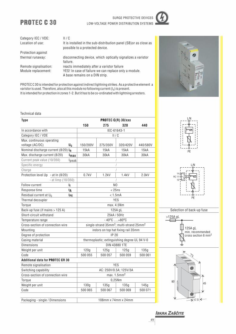
PRO CTEC (R) 30/xxx150 275 320 440
IEC-61643-1II / C
150/200V 275/350V 320/420V 440/580V
30kA 30kA 30kA
0.7kV 1.2kV 1.4kV 2.0kV
NO< 25ns
< 1.5mAYES
max. 4.5Nm125A gL
25kA / 50Hz- 40 C ….+80 C
single-strand 35mm ; multi-strand 25mmindors on top hat fixing rail 35mm
IP 20thermoplastic; extinguishing degree
DIN 43880 1TE120g 125g 125g 135g
15kA 15kA 15kA 15kA30kA
UL 94 V-0
YESAC: 250V/0.5A; 125V/3A
max. 1.5mm0,25Nm
130g 135g 135g 145g
108mm x 74mm x 24mm
o o
2 2
2
///
/
500 055 500 057 500 059 500 061
500 065 500 067 500 069 500 071
Type
UcInImax
tA
In accordance withCategory IEC / VDEMax. continuous operating
(AC/DC)Nominal discharge current (8/20)Max. discharge current (8/20)
Protection level Up - at In (8/20)
Follow currentResponse time
Thermal decoupler
Back-up fuse (if mains > 125 A)Short-circuit withstandTemperature rangeCross-section of connection wireMountingDegree of protectionCasing materialDimensions
Code
voltage
Residual current at Uc
Torque
Weight per unit
Remote signalisationSwitching capabilityCross-section of connection wireTorqueWeight per unitCode
Packaging - single / Dimensions
I
I
Additional data for TEC R 30
f
PE
PRO C
Current peak value (10/350)Specific energyCharge
- at Iimp (10/350)
Ipeak
PRO CTEC 30PRO CTEC 30
49
Technical data
Category IEC / VDE: II / CLocation of use: It is installed in the sub-distribution panel (SB)or as close as
possible to a protected device.
Module replacement: YES! In case of failure we can replace only a module.A base remains on a DIN strip.
Protection againstthermal runaway: disconnecting device, which optically signalizes a varistor
failure.Remote signalisation: reacts immediately after a varistor failure
PROTEC C 30 is intended for protection against indirect lightning strikes. As a protective element avaristor is used. Therefore, also at this module no following current (I ) is present.It is intended for protection in zones 1-2.
FBut it has to be co-ordinated with lightning arresters.
>125A gL
125A gLmin. recommendedcross section 6 mm2
Selection of back-up fuse
SURGE PROTECTIVE DEVICES
LOW-VOLTAGE POWER DISTRIBUTION SYSTEMS
9045
17.5
72
L/N
PE
PE
L/N
141112
RC

>125A gL
125A gLmin. recommendedcross section 6 mm2
Selection of back-up fuse
9045
17.5
72
Type
UcInImax
tA
In accordance withCategory IEC / VDEMax. continuous operating
(AC/DC)Nominal discharge current (8/20)Max. discharge current (8/20)
Protection level Up - at In (8/20)
Follow currentResponse time
Thermal decoupler
Back-up fuse (if mains > 125 A)Short-circuit withstandTemperature rangeCross-section of connection wireMountingDegree of protectionCasing materialDimensions
Code
voltage
Residual current at Uc
Torque
Weight per unit
Remote signalisationSwitching capabilityCross-section of connection wireTorqueWeight per unitCode
Packaging - single / Dimensions
I
I
Additional data for TEC R 20
f
PE
PRO C
Current peak value (10/350)Specific energyCharge
- at Iimp (10/350)
Ipeak
PRO CTEC 20PRO CTEC 20
50
PRO CTEC (R) 20/xxx150 275 320 440
IEC-61643-1II / C
150/200V 275/350V 320/420V 440/580V10kA20kA 20kA 20kA 20kA
0.6kV 1.1kV 1.3kV 1.9kV
NO< 25ns
< 1.5mAYES
max. 4.5Nm125A gL
25kA / 50Hz- 40 C ….+80 C
single-strand 35mm ; multi-strand 25mmindors on top hat fixing rail 35mm
IP 20thermoplastic; extinguishing degree
DIN 43880 1TE120g 125g 125g 135g
10kA 10kA 10kA
UL 94 V-0
YESAC: 250V/0.5A; 125V/3A
max. 1.5mm0,25Nm
130g 135g 135g 145g
108mm x 74mm x 24mm
o o
2 2
2
///
/
500 037 500 039 500 041 500 043
500 045 500 047 500 049 500 051
Technical data
Category IEC / VDE: II / CLocation of use: It is installed in the sub-distribution panel (SB)or as close as
possible to a protected device.
Module replacement: YES! In case of failure we can replace only a module.A base remains on a DIN strip.
Protection againstthermal runaway: disconnecting device, which optically signalizes a varistor
failure.Remote signalisation: reacts immediately after a varistor failure
PROTEC C 20 is intended for protection against indirect lightning strikes. As a protective element avaristor is used. Therefore, also at this module no following current (I ) is present.It is intended for protection in zones 1-2.
FBut it has to be co-ordinated with lightning arresters.
SURGE PROTECTIVE DEVICES
LOW-VOLTAGE POWER DISTRIBUTION SYSTEMS
L/N
PE
PE
L/N
141112
RC

L/N
PE
PE
L/N
141112
RC
>125A gL
125A gLmin. recommendedcross section 6 mm2
Selection of back-up fuse
9045
17.5
72
Type
UcInImax
tA
In accordance withCategory IEC / VDEMax. continuous operating
(AC/DC)Nominal discharge current (8/20)Max. discharge current (8/20)
Protection level Up - at In (8/20)
Follow currentResponse time
Thermal decoupler
Back-up fuse (if mains > 125 A)Short-circuit withstandTemperature rangeCross-section of connection wireMountingDegree of protectionCasing materialDimensions
Code
voltage
Residual current at Uc
Torque
Weight per unit
Remote signalisationSwitching capabilityCross-section of connection wireTorqueWeight per unitCode
Packaging - single / Dimensions
I
I
Additional data for TEC R 10
f
PE
PRO C
Current peak value (10/350)Specific energyCharge
- at Iimp (10/350)
Ipeak
PRO CTEC 10PRO CTEC 10
51
PRO CTEC (R) 10/xxx150 275 320 440
IEC-61643-1II / C
150/200V 275/350V 320/420V 440/580V5kA
10kA 10kA 10kA 10kA
0.5kV 1.0kV 1.2kV 1.8kV
NO< 25ns
< 1.5mAYES
max. 4.5Nm125A gL
10kA / 50Hz- 40 C ….+80 C
single-strand 35mm ; multi-strand 25mmindors on top hat fixing rail 35mm
IP 20thermoplastic; extinguishing degree
DIN 43880 1TE120g 125g 125g 135g
500 021 500 023 500 025 500 027
5kA 5kA 5kA
UL 94 V-0
YESAC: 250V/0.5A; 125V/3A
max. 1.5mm0,25Nm
130g 135g 135g 145g500 029 500 031 500 033 500 035
108mm x 74mm x 24mm
o o
2 2
2
///
/
Technical data
Category IEC / VDE: II / CLocation of use: It is installed in the sub-distribution panel (SB)or as close as
possible to a protected device.
Module replacement: YES! In case of failure we can replace only a module.A base remains on a DIN strip.
Protection againstthermal runaway: disconnecting device, which optically signalizes a varistor
failure.Remote signalisation: reacts immediately after a varistor failure
PROTEC C 10 is intended for protection against indirect lightning strikes. As a protective element avaristor is used. Therefore, also at this module no following current (I ) is present.It is intended for protection in zones 1-2.
FBut it has to be co-ordinated with lightning arresters.
SURGE PROTECTIVE DEVICES
LOW-VOLTAGE POWER DISTRIBUTION SYSTEMS

TNC/TNS Single Phase Network Dimensions Weight per unit CodePROTEC C 80/150 (2+0) DIN 43880 2TE 230g 500 073PROTEC C 80/275 (2+0) DIN 43880 2TE 240g 500 075PROTEC C 80/320 (2+0) DIN 43880 2TE 240g 500 077PROTEC C 80/440 (2+0) DIN 43880 2TE 250g 500 079PROTEC CR 80/150 (2+0) DIN 43880 2TE 240g 500 081PROTEC CR 80/275 (2+0) DIN 43880 2TE 250g 500 083PROTEC CR 80/320 (2+0) DIN 43880 2TE 250g 500 085PROTEC CR 80/440 (2+0) DIN 43880 2TE 260g 500 087
PRO CTEC 80 (2+0)PRO CTEC 80 (2+0)
52
N
N
L
L
PE
PE
14RC11
12
SURGE PROTECTIVE DEVICESLOW-VOLTAGE
POWER DISTRIBUTION SYSTEMS
EBB
With Remote Control2 x PROTEC CR
N N
Without Remote Control2 x PROTEC C
TNC/TNS Network (2+0)
Remote
Control
PE PE
L L
PRO CTEC PRO CTEC
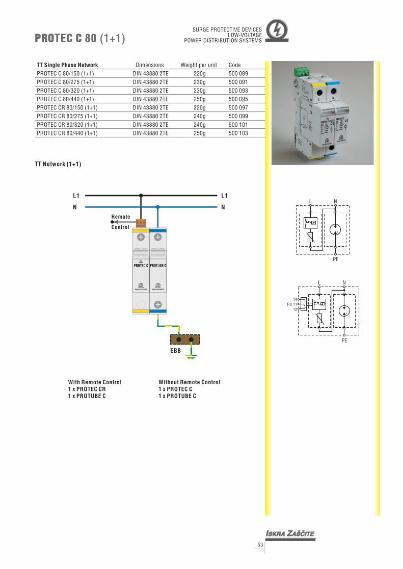
TT Dimensions Weight per unit CodePROTEC C 80/150 (1+1) DIN 43880 2TE 220g 500 089
Single Phase Network
PROTEC C 80/275 (1+1) DIN 43880 2TE 230g 500 091PROTEC C 80/320 (1+1) DIN 43880 2TE 230g 500 093PROTEC C 80/440 (1+1) DIN 43880 2TE 250g 500 095PROTEC CR 80/150 (1+1) DIN 43880 2TE 220g 500 097PROTEC CR 80/275 (1+1) DIN 43880 2TE 240g 500 099PROTEC CR 80/320 (1+1) DIN 43880 2TE 240g 500 101PROTEC CR 80/440 (1+1) DIN 43880 2TE 250g 500 103
PRO CTEC 80 (1+1)PRO CTEC 80 (1+1)
53
N
N
L
L
PE
PE
14RC 11
12
SURGE PROTECTIVE DEVICESLOW-VOLTAGE
POWER DISTRIBUTION SYSTEMS
With Remote Control1 x PROTEC CR1 x PROTUBE C
Without Remote Control1 x PROTEC C1 x PROTUBE C
TT Network (1+1)
Remote
Control
N N
L1 L1
EBB
PRO CTEC PRO CTUBE
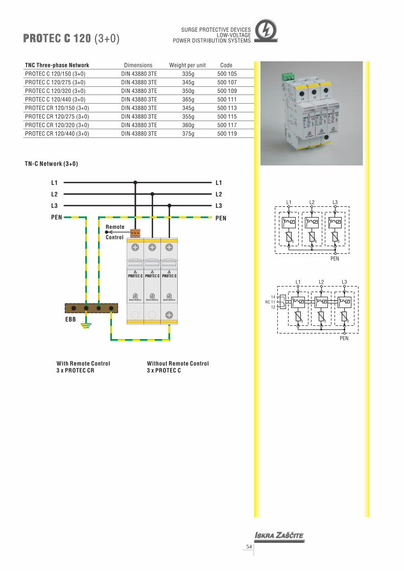
TNC Three-p Dimensions Weight per unit CodePROTEC C 120/150 (3+0) DIN 43880 3TE 335g 500 105
hase Network
PROTEC C 120/275 (3+0) DIN 43880 3TE 345g 500 107PROTEC C 120/320 (3+0) DIN 43880 3TE 350g 500 109PROTEC C 120/440 (3+0) DIN 43880 3TE 365g 500 111PROTEC CR 120/150 (3+0) DIN 43880 3TE 345g 500 113PROTEC CR 120/275 (3+0) DIN 43880 3TE 355g 500 115PROTEC CR 120/320 (3+0) DIN 43880 3TE 360g 500 117PROTEC CR 120/440 (3+0) DIN 43880 3TE 375g 500 119
PRO CTEC 120 (3+0)PRO CTEC 120 (3+0)
54
SURGE PROTECTIVE DEVICESLOW-VOLTAGE
POWER DISTRIBUTION SYSTEMS
With Remote Control3 x PROTEC CR
Without Remote Control3 x PROTEC C
L3 L3
L2 L2
L1 L1
TN-C Network (3+0)
PEN PEN
EBB
Remote
Control
PRO CTEC PRO CTEC PRO CTEC
L3
L3
L2
L2
L1
L1
PEN
PEN
14RC 11
12

TNS Three-phase Network Dimensions Weight per unit CodePROTEC C 160/150 (4+0) DIN 43880 4TE 450g 500 121PROTEC C 160/275 (4+0) DIN 43880 4TE 460g 500 123PROTEC C 160/320 (4+0) DIN 43880 4TE 465g 500 125PROTEC C 160/440 (4+0) DIN 43880 4TE 480g 500 127PROTEC CR 160/150 (4+0) DIN 43880 4TE 460g 500 129PROTEC CR 160/275 (4+0) DIN 43880 4TE 470g 500 131PROTEC CR 160/320 (4+0) DIN 43880 4TE 475g 500 133PROTEC CR 160/440 (4+0) DIN 43880 4TE 490g 500 135
PRO CTEC 160 (4+0)PRO CTEC 160 (4+0)
55
SURGE PROTECTIVE DEVICESLOW-VOLTAGE
POWER DISTRIBUTION SYSTEMS
NL3L2L1
PE
14RC 11
12
NL3L2L1
PEEBB
With Remote Control4 x PROTEC CR
N N
Without Remote Control4 x PROTEC C
TN-S Network (4+0)
Remote
Control
PE PE
L3 L3
L2 L2
L1 L1
PRO CTEC PRO CTEC PRO CTEC PRO CTEC

TT Dimensions Weight per unit CodePROTEC C 160/150 (3+1) DIN 43880 4TE 425g 500 137
Three-phase Network
PROTEC C 160/275 (3+1) DIN 43880 4TE 435g 500 139PROTEC C 160/320 (3+1) DIN 43880 4TE 440g 500 141PROTEC C 160/440 (3+1) DIN 43880 4TE 455g 500 143PROTEC CR 160/150 (3+1) DIN 43880 4TE 435g 500 145PROTEC CR 160/275 (3+1) DIN 43880 4TE 445g 500 147PROTEC CR 160/320 (3+1) DIN 43880 4TE 450g 500 149PROTEC CR 160/440 (3+1) DIN 43880 4TE 465g 500 151
NL3L2L1
PE
PRO CTEC 160 (3+1)PRO CTEC 160 (3+1)
56
SURGE PROTECTIVE DEVICESLOW-VOLTAGE
POWER DISTRIBUTION SYSTEMS
NL3L2L1
PE
14RC 11
12
With Remote Control3 x PROTEC CR1 x PROTUBE C
Without Remote Control3 x PROTEC C1 x PROTUBE C
TT Network (3+1)
Remote
Control
N N
L3 L3
L2 L2
L1 L1
EBB
PRO CTEC PRO CTEC PRO CTEC PRO CTUBE

57
PRO CTUBEPRO CTUBE
Type
UcInImax
tA
In accordance withCategory IEC / VDEMax. continuous operating
(AC)Nominal discharge current (8/20)Max. discharge current (8/20)
- at (1.2/50)Follow currentResponse time
Temperature rangeCross-section of connection wireMountingDegree of protectionCasing materialDimensions
Code
voltage
Torque
Weight per unit
Packaging - single / Dimensions
If
Current peak value (10/350)
Protection level Up - at In (8/20)
IpeakSpecific energyCharge
Thermal decoupler
Back-up fuseShort-circuit withstand
Residual current at Uc
Remote signalisationSwitching capabilityCross-section of connection wireTorqueWeight per unitCode
I
Additional data for TUBE
PE
PRO C
PRO CTUBE (R)
IEC-61643-1II / C
255V20kA40kA
1.2kV> 100A< 100ns
//
max. 4.5Nm//
- 40 C ….+80 C
indors on top hat fixing rail 35mmIP 20
thermoplastic; extinguishing degree V-0DIN 43880 1TE
105g503 005
o o
single-strand 35mm ; multi-strand 25mm
UL 94
108mm x 74mm x 24mm
2 2
/
/
//
//////
Technical data
SURGE PROTECTIVE DEVICES
LOW-VOLTAGE POWER DISTRIBUTION SYSTEMS
N
Category IEC / VDE: II / CLocation of use: It is installed in the sub-distribution panel (SB) or as close as
possible to a protected device.Module replacement: YES! In case of failure we can replace only a module.
A base remains on a DIN strip.
PROTUBE C is intended for protection against indirect lightning strikes. It is used as galvanicseparation between N-PE conductor in 1+1 and 3+1 systems (TT network).It is intended for protection in zones 1-2. But it has to be co-ordinated with lightning arresters.
PE
9045
17.5
72
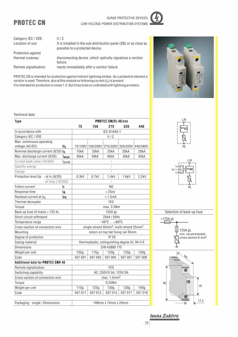
Type
UcInImax
tA
In accordance withCategory IEC / VDEMax. continuous operating
(AC/DC)Nominal discharge current (8/20)Max. discharge current (8/20)
Protection level Up - at In (8/20)
Follow currentResponse time
Thermal decoupler
Back-up fuse (if mains > 125 A)Short-circuit withstandTemperature rangeCross-section of connection wireMountingDegree of protectionCasing materialDimensions
Code
voltage
Residual current at Uc
Torque
Weight per unit
Remote signalisationSwitching capabilityCross-section of connection wireTorqueWeight per unitCode
Packaging - single / Dimensions
I
I
Additional data for TEC R 40
f
PE
PRO CN
Current peak value (10/350)Specific energyCharge
- at Iimp (10/350)
Ipeak
PRO CNTECPRO CNTEC
58
PRO CNTEC (R) 40/xxx75 150 275 320 440
IEC-61643-1II / C
75/100V 150/200V 275/350V 320/420V 440/580V10kA 20kA 240kA 40kA 40kA 40kA
0.3kV 0.7kV 1.4kV 1.6kV 2.2kV
NO< 25ns< 1.5mA
YESmax. 3.5Nm
125A gL25kA / 50Hz
- 40 C ….+80 Csingle-strand 35mm ; multi-strand 25mm
indors on top hat fixing rail 35mmIP 20
thermoplastic; extinguishing degreeDIN 43880 1TE
105g 115g 120g 120g 130g
0kA 20kA 20kA40kA
UL 94 V-0
YESAC: 250V/0.5A; 125V/3A
max. 1.5mm0,25Nm
115g 125g 130g 130g 140g
108mm x 74mm x 24mm
o o
2 2
2
///
/
507 001 507 003 507 005 507 007 507 009
507 011 507 013 507 015 507 017 507 019
Technical data
Category IEC / VDE: II / CLocation of use: It is installed in the sub-distribution panel (SB) or as close as
possible to a protected device.Protection againstthermal runaway: disconnecting device, which optically signalizes a varistor
failure.Remote signalisation: reacts immediately after a varistor failure
PROTEC CN is intended for protection against indirect lightning strikes. As a protective element avaristor is used. Therefore, also at this module no following current (I ) is present.It is intended for protection in zones 1-2. But it has to be co-ordinated with lightning arresters.
F
L/N
PE
PE
L/N
>125A gL
125A gLmin. recommendedcross section 6 mm2
Selection of back-up fuse
SURGE PROTECTIVE DEVICES
LOW-VOLTAGE POWER DISTRIBUTION SYSTEMS
14RC 11
12
66
4590
17.5

59
PRO CNTUBEPRO CNTUBE
Type
UcInImax
tA
In accordance withCategory IEC / VDEMax. continuous operating
(AC)Nominal discharge current (8/20)Max. discharge current (8/20)
- at (1.2/50)Follow currentResponse time
Temperature rangeCross-section of connection wireMountingDegree of protectionCasing materialDimensions
Code
voltage
Torque
Weight per unit
Packaging - single / Dimensions
I
Additional data for TUBE N
f
PRO C
Current peak value (10/350)
Protection level Up - at In (8/20)
IpeakSpecific energyCharge
Thermal decoupler
Back-up fuseShort-circuit withstand
Residual current at Uc
Remote signalisationSwitching capabilityCross-section of connection wireTorqueWeight per unitCode
IPE
PRO CNTUBE
IEC-61643-1II / C
255V20kA40kA
1.2kV> 100A< 100ns
//
max. 3.5Nm//
- 40 C ….+80 C
indors on top hat fixing rail 35mmIP 20
thermoplastic; extinguishing degree V-0DIN 43880 1TE
105g503 009
o o
single-strand 35mm ; multi-strand 25mm
UL 94
108mm x 74mm x 24mm
2 2
/
/
//
//////
Technical data
SURGE PROTECTIVE DEVICES
LOW-VOLTAGE POWER DISTRIBUTION SYSTEMS
N
Category IEC / VDE: II / CLocation of use: It is installed in the sub-distribution panel (SB) or as close as
possible to a protected device.
PROTUBE CN is intended for protection against indirect lightning strikes. It is used as galvanicseparation between N-PE conductor in 1+1 and 3+1 systems (TT network).It is intended for protection in zones 1-2. But it has to be co-ordinated with lightning arresters.
PE
66
4590
17.5
I ZSKRA A[^ITE
Uc = 255 V
In = 20 kA
Imax = 40 kA
AC
PRO CNTUBECT2
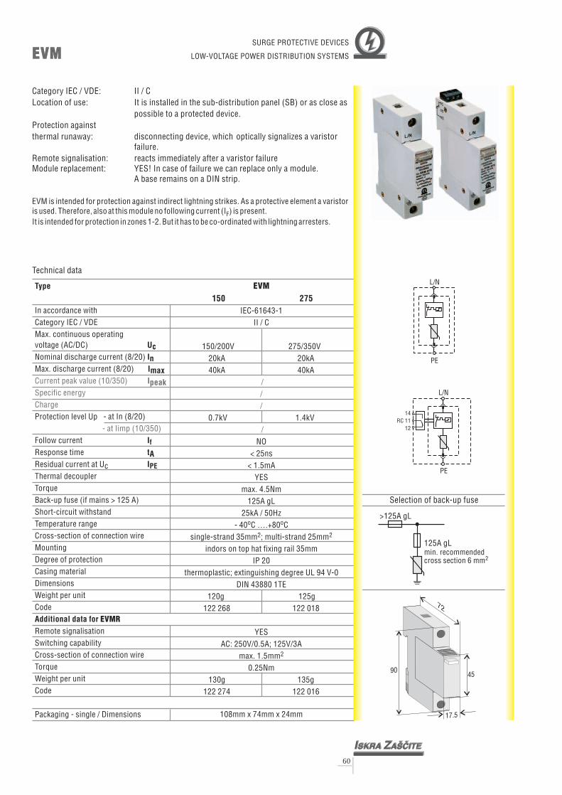
Type
UcInImax
tA
In accordance withCategory IEC / VDEMax. continuous operating
(AC/DC)Nominal discharge current (8/20)Max. discharge current (8/20)
Protection level Up - at In (8/20)
Follow currentResponse time
Thermal decoupler
Back-up fuse (if mains > 125 A)Short-circuit withstandTemperature rangeCross-section of connection wireMountingDegree of protectionCasing materialDimensions
Code
voltage
Residual current at Uc
Torque
Weight per unit
Remote signalisationSwitching capabilityCross-section of connection wireTorqueWeight per unitCode
Packaging - single / Dimensions
I
I
Additional data for
f
PE
EVMR
Current peak value (10/350)Specific energyCharge
- at Iimp (10/350)
Ipeak
EVMEVM
60
EVM150 275
IEC-61643-1II / C
150/200V 275/350V20kA 240kA 40kA
0.7kV 1.4kV
NO< 25ns
< 1.5mAYES
max. 4.5Nm125A gL
25kA / 50Hz- 40 C ….+80 C
single-strand 35mm ; multi-strand 25mmindors on top hat fixing rail 35mm
IP 20thermoplastic; extinguishing degree
DIN 43880 1TE120g 125g
0kA
UL 94 V-0
YESAC: 250V/0.5A; 125V/3A
max. 1.5mm0.25Nm
130g 135g
108mm x 74mm x 24mm
o o
2 2
2
///
/
122 268 122 018
122 274 122 016
Technical data
Category IEC / VDE: II / CLocation of use: It is installed in the sub-distribution panel (SB) or as close as
possible to a protected device.Protection againstthermal runaway: disconnecting device, which optically signalizes a varistor
failure.Remote signalisation: reacts immediately after a varistor failureModule replacement: YES! In case of failure we can replace only a module.
A base remains on a DIN strip.
EVM is intended for protection against indirect lightning strikes. As a protective element a varistoris used. Therefore, also at this module no following current (I ) is present.It is intended for protection in zones 1-2.
FBut it has to be co-ordinated with lightning arresters.
>125A gL
125A gLmin. recommendedcross section 6 mm2
Selection of back-up fuse
SURGE PROTECTIVE DEVICES
LOW-VOLTAGE POWER DISTRIBUTION SYSTEMS
9045
17.5
72
L/N
PE
PE
L/N
141112
RC

PRO CMTEC (R) 80/xxx (2+0)150 275 320 440
IEC-61643-1II / C
. 150/200V 275/350V 320/420V 440/580V
40kA 40kA 40kA 4///
0.7kV 1.4kV 1.5kV 2.2kV
NO< 25ns< 1.5mA
YESmax. 3.5Nm
100A gL25kA / 50Hz
- 40 C ….+80 Csingle-strand 25mm ; multi-strand 16mm
indors on top hat fixing rail 35mmIP 20
thermoplastic; extinguishing degreeDIN 43880 1TE
130g 140g 140g 150g
15kA/pole 15kA/pole 15kA/pole 15kA/pole/pole /pole /pole 0kA/pole
/
single-strand 6mm ; multi-strand 4mm
UL 94 V-0
508 001 508 003 508 005 508 008
YESAC: 250V/0.5A; 125V/3A
max. 1.5mm0,25Nm
140g 150g 150g 160g508 009 508 011 508 013 508 015
108mm x 74mm x 24mm
o o
2 2
2 2
2
Type
UcInImax
tA
In accordance withCategory IEC / VDEMax. continuous operating
(AC/DC)Nominal discharge current (8/20)Max. discharge current (8/20)
Protection level Up/pole - at In (8/20)
Follow currentResponse time
Thermal decoupler
Back-up fuse (if mains > 100 A)Short-circuit withstandTemperature rangeCross-section of connection wire
MountingDegree of protectionCasing materialDimensions
Code
voltage
Residual current at Uc
Torque
Cross-section of connection wire L or N
Weight per unit
Remote signalisationSwitching capabilityCross-section of connection wireTorqueWeight per unitCode
Packaging - single / Dimensions
I
I
Additional data for TEC MR 80 (2+0)
f
PE
PRO C
Current peak value (10/350)Specific energyCharge
- at Iimp (10/350)
Ipeak
PRO CM 80TEC (2+0)PRO CM 80TEC (2+0)
61
Technical data
Category IEC / VDE: II / CLocation of use: It is installed in the sub-distribution board (SB)or as close as
possible to a protected device.
Module replacement: YES! In case of failure we can replace only a module.A base remains on a DIN strip.
Protection againstthermal runaway: disconnecting device, which optically signalizes a varistor
failure.Remote signalisation: reacts immediately after a varistor failure
PROTEC CM 80 (2+0) is intended for protection against indirect lightning strikes. As a protectiveelement a varistor is used. Therefore, also at this module no following current (I ) is present.With a single PROTEC CM 80 (2+0) module a two-terminal protection is enabled (L-PE and N-PE).It is intended for protection in zones 1-2. But it has to be co-ordinated with lightning arresters.
F
>100A gL
100A gLmin. recommendedcross section 6 mm2
Selection of back-up fuse
L
L
N
N
141112
RC
SURGE PROTECTIVE DEVICES
LOW-VOLTAGE POWER DISTRIBUTION SYSTEMS
PE
PE
90
68
17,5

PRO CMTEC (R) 80/xxx (1+1)
150 275 320 440
IEC-61643-1
II / C
150/200V 275/350V 320/420V 440/580V
/
0.7kV 1.4kV 1.5kV 2.2kV
/
NO/
< 25ns/< 100ns
< 1.5mA
YES
max. 3.5Nm
100A gL
25kA/50Hz
- 40 C ….+80 C
indors on top hat fixing rail 35mm
IP 20
thermoplastic; extinguishing degree UL 94 V-0
DIN 43880 1TE
15kA / 20kA
40kA / 40kA
/
/
100A
single-strand 25mm ; multi-strand 16mm
single-strand 6mm ; multi-strand 4mm
RMS
o o
2 2
2 2
11
120g 130g 130g 140g
508 053 508 055 508 057 508 059
108mm x 74mm x 24mm
0g 120g 120g 130g
508 045 508 047 508 049 508 051
YES
AC: 250V/0.5A; 125V / 3A
max. 1.5mm
0,25Nm
2
Technical data
Type
Uc
In accordance with
Category IEC / VDE
Max. continuous operating(AC/DC)
Protection level Up/pole - at In (8/20) (MOV)
Thermal decoupler
Back-up fuse (if mains > 100 A)
Short-circuit withstand
Temperature range
Cross-section of connection wire
Mounting
Degree of protection
Casing material
Dimensions
Code
voltage
Nominal discharge current (8/20) (MOV/GDT)
Max. discharge current (8/20) (MOV/GDT)
Follow current (MOV/GDT)
Response time (MOV/GDT)
Residual current at Uc
Torque
Cross-section of connection wire L or N
Weight per unit
Remote signalisation
Switching capability
Cross-section of connection wire
Torque
Weight per unit
Code
Packaging - single / Dimensions
InImax
IftAIPE
Additional data for TECPRO CMR 80 (1+1)
Current peak value (10/350)
Specific energy
Charge
Ipeak
- at Iimp (10/350)
PRO CM 80TEC (1+1)PRO CM 80TEC (1+1)
62
Category IEC / VDE: II / CLocation of use: It is installed in the sub-distribution board (SB)or as close as
possible to a protected device.
Module replacement: YES! In case of failure we can replace only a module.A base remains on a DIN strip.
Protection againstthermal runaway: disconnecting device, which optically signalizes a varistor
failure.Remote signalisation: reacts immediately after a varistor failure
PROTEC CM 80 (1+1) is intended for protection against indirect lightning strikes. As a protectiveelements varistor and GDT are used.With a single PROTEC CM 80 (1+1) module a two-terminal protection is enabled (L-PE and N-PE).It is intended for protection in zones 1-2. But it has to be co-ordinated with lightning arresters.
>100A gL
100A gLmin. recommendedcross section 6 mm2
Selection of back-up fuse
L
L
N
N
14RC 11
12
SURGE PROTECTIVE DEVICES
LOW-VOLTAGE POWER DISTRIBUTION SYSTEMS
PE
PE
90
68
17,5

PRO CTTEC (R) 120/xxx (3+0)150 275 320 440
IEC-61643-1II / C
150/200V 275/350V 320/420V 440/580V
40kA 40kA 40kA 4
0.7kV 1.4kV 1.5kV 2.2kV
NO< 25ns< 1.5mA
YESmax. 3.5Nm
100A gL25kA / 50Hz
- 40 C ….+80 Csingle-strand 25mm ; multi-strand 16mm
indors on top hat fixing rail 35mmIP 20
thermoplastic; extinguishing degreeDIN 43880 2TE
235g 255g 255g 275g
15kA/pole 15kA/pole 15kA/pole 15kA/pole/pole /pole /pole 0kA/pole
single-strand 6mm ; multi-strand 4mm
UL 94 V-0
YESAC: 250V/0.5A; 125V/3A
max. 1.5mm0,25Nm
245g 265g 265g 285g
108mm x 74mm x 47mm
o o
2 2
2 2
2
///
/
508 061 508 063 508 065 508 068
508 069 508 071 508 073 508 075
Type
UcInImax
tA
In accordance withCategory IEC / VDEMax. continuous operating
(AC/DC)Nominal discharge current (8/20)Max. discharge current (8/20)
Protection level Up/pole - at In (8/20)
Follow currentResponse time
Thermal decoupler
Back-up fuse (if mains > 100 A)Short-circuit withstandTemperature rangeCross-section of connection wire
MountingDegree of protectionCasing materialDimensions
Code
voltage
Residual current at Uc
Torque
Cross-section of connection wire L or N
Weight per unit
Remote signalisationSwitching capabilityCross-section of connection wireTorqueWeight per unitCode
Packaging - single / Dimensions
I
I
Additional data for TEC R 120 (3+0)
f
PE
PRO CT
Current peak value (10/350)Specific energyCharge
- at Iimp (10/350)
Ipeak
PRO CT 120TEC (3+0)PRO CT 120TEC (3+0)
63
Technical data
Category IEC / VDE: II / CLocation of use: It is installed in the sub-distribution board (SB)or as close as
possible to a protected device.
Module replacement: YES! In case of failure we can replace only a module.A base remains on a DIN strip.
Protection againstthermal runaway: disconnecting device, which optically signalizes a varistor
failure.Remote signalisation: reacts immediately after a varistor failure
PROTEC CT 120 (3+0) is intended for protection against indirect lightning strikes. As a protectiveelement a varistor is used. Therefore, also at this module no following current (I ) is present.It is intended for protection in zones 1-2. But it has to be co-ordinated with lightning arresters.
F
>100A gL
100A gLmin. recommendedcross section 6 mm2
Selection of back-up fuse
L1
L1
L2
L2
L3
L3
14RC 11
12
SURGE PROTECTIVE DEVICES
LOW-VOLTAGE POWER DISTRIBUTION SYSTEMS
PEN
PEN
90
68
35

PRO CTTEC (R) 160/xxx (4+0)150 275 320 440
IEC-61643-1II / C
150/200V 275/350V 320/420V 440/580V
40kA 40kA 40kA 4
0.7kV 1.4kV 1.5kV 2.2kV
NO< 25ns
< 1.5mAYES
max. 3.5Nm100A gL
25kA / 50Hz- 40 C ….+80 C
single-strand 25mm ; multi-strand 16mm
indors on top hat fixing rail 35mmIP 20
thermoplastic; extinguishing degreeDIN 43880 2TE
260g 280g 280g 300g
15kA/pole 15kA/pole 15kA/pole 15kA/pole/pole /pole /pole 0kA/pole
single-strand 6mm ; multi-strand 4mm
UL 94 V-0
YESAC: 250V/0.5A; 125V/3A
max. 1.5mm0,25Nm
270g 290g 290g 310g
108mm x 74mm x 47mm
o o
2 2
2 2
2
///
/
508 077 508 079 508 081 508 083
508 085 508 087 508 089 508 091
Type
UcInImax
tA
In accordance withCategory IEC / VDEMax. continuous operating
(AC/DC)Nominal discharge current (8/20)Max. discharge current (8/20)
Protection level Up/pole - at In (8/20)
Follow currentResponse time
Thermal decoupler
Back-up fuse (if mains > 100 A)Short-circuit withstandTemperature rangeCross-section of connection wire
MountingDegree of protectionCasing materialDimensions
Code
voltage
Residual current at Uc
Torque
Cross-section of connection wire L or N
Weight per unit
Remote signalisationSwitching capabilityCross-section of connection wireTorqueWeight per unitCode
Packaging - single / Dimensions
I
I
Additional data for TEC R 160 (4+0)
f
PE
PRO CT
Current peak value (10/350)Specific energyCharge
- at Iimp (10/350)
Ipeak
PRO CT 160TEC (4+0)PRO CT 160TEC (4+0)
64
Technical data
Category IEC / VDE: II / CLocation of use: It is installed in the sub-distribution board (SB)or as close as
possible to a protected device.
Module replacement: YES! In case of failure we can replace only a module.A base remains on a DIN strip.
Protection againstthermal runaway: disconnecting device, which optically signalizes a varistor
failure.Remote signalisation: reacts immediately after a varistor failure
PROTEC CT 160 (4+0) is intended for protection against indirect lightning strikes. As a protectiveelement a varistor is used. Therefore, also at this module no following current (I ) is present.It is intended for protection in zones 1-2. But it has to be co-ordinated with lightning arresters.
F
>100A gL
100A gLmin. recommendedcross section 6 mm2
Selection of back-up fuse
L1
L1
L2
L2
L3
L3
N
N
14RC 11
12
SURGE PROTECTIVE DEVICES
LOW-VOLTAGE POWER DISTRIBUTION SYSTEMS
PE
PE
90
68
35

PRO CTTEC (R) 160/xxx (3+1)
150 275 320 440
IEC-61643-1
II / C
150/200V 275/350V 320/420V 440/580V
40kA 40kA 40kA 4
0.7kV 1.4kV 1.5kV 2.2kV
NO / 100A
< 25ns/100ns
< 1.5mA
YES
max. 3.5Nm
100A gL
25kA / 50Hz
- 40 C ….+80 C
indors on top hat fixing rail 35mm
IP 20
thermoplastic; extinguishing degree
DIN 43880 2TE
15kA/20kA 15kA/20kA 15kA/20kA 15kA/20kA
/40kA /40kA /40kA 0kA/40kA
single-strand 25mm ; multi-strand 16mm
single-strand 6mm ; multi-strand 4mm
UL 94 V-0
YES
AC: 250V/0.5A; 125V/3A
max. 1.5mm
0.25Nm
108mm x 74mm x 47mm
RMS
o o
2 2
2 2
2
/
/
/
/
240g 260g 260g 280g
508 093 508 095 508 097 508 099
250g 270g 270g 290g
508 101 508 103 508 105 508 107
Technical data
PRO CT 160TEC (3+1)PRO CT 160TEC (3+1)
65
Category IEC / VDE: II / CLocation of use: It is installed in the sub-distribution board (SB)or as close as
possible to a protected device.
Module replacement: YES! In case of failure we can replace only a module.A base remains on a DIN strip.
Protection againstthermal runaway: disconnecting device, which optically signalizes a varistor
failure.Remote signalisation: reacts immediately after a varistor failure
PROTEC CT 160 (3+1) is intended for protection against indirect lightning strikes. As a protectiveelements varistor and GDT are used.With a single PROTEC CT 160 (3+1) module a two-terminal protection is enabled (L-PE and N-PE).It is intended for protection in zones 1-2. But it has to be co-ordinated with lightning arresters.
>100A gL
100A gLmin. recommendedcross section 6 mm2
Selection of back-up fuse
SURGE PROTECTIVE DEVICES
LOW-VOLTAGE POWER DISTRIBUTION SYSTEMS
90
68
35
L1
L1
L2
L2
L3
L3
N
N
14RC 11
12
PE
PE
Type
Uc
In accordance with
Category IEC / VDE
Max. continuous operating(AC/DC)
Protection level Up/pole - at In (8/20) (MOV)
Thermal decoupler
Back-up fuse (if mains > 100 A)
Short-circuit withstand
Temperature range
Cross-section of connection wire
Mounting
Degree of protection
Casing material
Dimensions
Code
voltage
Nominal discharge current (8/20) (MOV/GDT)
Max. discharge current (8/20) (MOV/GDT)
Follow current (MOV/GDT)
Response time (MOV/GDT)
Residual current at Uc
Torque
Cross-section of connection wire L or N
Weight per unit
Remote signalisation
Switching capability
Cross-section of connection wire
Torque
Weight per unit
Code
Packaging - single / Dimensions
InImax
IftAIPE
Additional data for TECPRO CTR 160 (3+1)
Current peak value (10/350)
Specific energy
Charge
Ipeak
- at Iimp (10/350)

PRO CMTEC (R) xxG10G 30G
IEC-61643-1II / C
. 320/420V 320
///
1.4kV 1.6kV
NO< 100ns
YESmax. 3.5Nm
100A gL25kA / 50Hz
- 40 C ….+80 Csingle-strand 25mm ; multi-strand 16mm
indors on top hat fixing rail 35mmIP 20
thermoplastic; extinguishing degreeDIN 43880 1TE
110g 140g
/420V5kA/pole 10kA/pole
10kA/pole 20kA/pole
/
/
single-strand 6mm ; multi-strand 4mm
UL 94 V-0
508 017 508 019
YESAC: 250V/0.5A; 125V/3A
max. 1.5mm0,25Nm
120g 150g508 023 508 025
108mm x 74mm x 24mm
o o
2 2
2 2
2
Type
UcInImax
tA
In accordance withCategory IEC / VDEMax. continuous operating
(AC/DC)Nominal discharge current (8/20)Max. discharge current (8/20)
Protection level Up/pole - at In (8/20)
Follow currentResponse time
Thermal decoupler
Back-up fuse (if mains > 100 A)Short-circuit withstandTemperature rangeCross-section of connection wire
MountingDegree of protectionCasing materialDimensions
Code
voltage
Residual current at Uc
Torque
Cross-section of connection wire L or N
Weight per unit
Remote signalisationSwitching capabilityCross-section of connection wireTorqueWeight per unitCode
Packaging - single / Dimensions
I
I
Additional data for TEC MR G
f
PE
PRO C
Current peak value (10/350)Specific energyCharge
- at Iimp (10/350)
Ipeak
PRO CM GTECPRO CM GTEC
66
Technical data
Category IEC / VDE: II / CLocation of use: It is installed in the sub-distribution board (SB)or as close as
possible to a protected device.
Module replacement: YES! In case of failure we can replace only a module.A base remains on a DIN strip.
Protection againstthermal runaway: disconnecting device, which optically signalizes a varistor
failure.Remote signalisation: reacts immediately after a varistor failure
PROTEC CM G is intended for protection against indirect lightning strikes. As a protective elementsvaristor and GDT are used. Therefore, also at this module no following current (I ) is present.With a single PROTEC CM G module a two-terminal protection is enabled (L-PE and N-PE).It is intended for protection in zones 1-2. But it has to be co-ordinated with lightning arresters.
F
>100A gL
100A gLmin. recommendedcross section 6 mm2
Selection of back-up fuse
SURGE PROTECTIVE DEVICES
LOW-VOLTAGE POWER DISTRIBUTION SYSTEMS
L
L
N
N
141112
RC
PE
PE
90
68
17,5
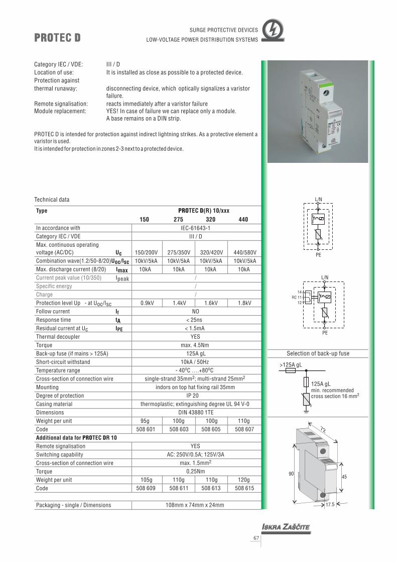
>125A gL
125A gLmin. recommendedcross section 16 mm2
Selection of back-up fuse
9045
17.5
72
Type
UcUoc
Imax
tA
In accordance withCategory IEC / VDEMax. continuous operating
(AC/DC)Combination wave(1.2/50-8/20)Max. discharge current (8/20)
Protection level Up - atFollow currentResponse time
Thermal decoupler
Back-up fuse (if mains > 125A)Short-circuit withstandTemperature rangeCross-section of connection wireMountingDegree of protectionCasing materialDimensions
Code
voltage
Uoc/Isc
Residual current at Uc
Torque
Weight per unit
Remote signalisationSwitching capabilityCross-section of connection wireTorqueWeight per unitCode
Packaging - single / Dimensions
/Isc
I
I
Additional data for TEC R 10
f
PE
PRO D
Current peak value (10/350)Specific energyCharge
Ipeak
PRO DTECPRO DTEC
67
Technical data
Category IEC / VDE: III / DLocation of use: It is installed as close as possible to a protected device.Protection againstthermal runaway: disconnecting device, which optically signalizes a varistor
failure.Remote signalisation: reacts immediately after a varistor failureModule replacement: YES! In case of failure we can replace only a module.
A base remains on a DIN strip.
PROTEC D is intended for protection against indirect lightning strikes. As a protective element avaristor is used.It is intended for protection in zones 2-3 next to a protected device.
SURGE PROTECTIVE DEVICES
LOW-VOLTAGE POWER DISTRIBUTION SYSTEMS
PRO DTEC (R) 10/xxx150 275 320 440
IEC-61643-1III / D
150/200V 275/350V 320/420V 440/580V
10kA 10kA 10kA 1
0.9kV 1.4kV 1.6kV 1.8kVNO
< 25ns< 1.5mA
YESmax. 4.5Nm
125A gL10kA / 50Hz
- 40 C ….+80 Csingle-strand 35mm ; multi-strand 25mm
indors on top hat fixing rail 35mmIP 20
thermoplastic; extinguishing degreeDIN 43880 1TE
95g 100g 100g 110g
10kV/5kA 10kV/5kA 10kV/5kA 10kV/5kA0kA
UL 94 V-0
YESAC: 250V/0.5A; 125V/3A
max. 1.5mm0,25Nm
105g 110g 110g 120g
108mm x 74mm x 24mm
o o
2 2
2
///
508 601 508 603 508 605 508 607
508 609 508 611 508 613 508 615
L/N
PE
PE
L/N
141112
RC

Type
UcUoc
Imax
tA
In accordance withCategory IEC / VDEMax. continuous operating
(AC/DC)Combination wave(1.2/50-8/20)Max. discharge current (8/20)
Protection level Up/pole - atFollow currentResponse time
Thermal decoupler
Back-up fuse (if mains > 63A)Short-circuit withstandTemperature rangeCross-section of connection wireMountingDegree of protectionCasing materialDimensions
Code
voltage
Uoc/Isc
Residual current at Uc
Torque
Weight per unit
Remote signalisationSwitching capabilityCross-section of connection wireTorqueWeight per unitCode
Packaging - single / Dimensions
/Isc
I
I
Additional data for TEC R
f
PE
PRO DM
Current peak value (10/350)Specific energyCharge
Ipeak
PRO DMTECPRO DMTEC
68
Technical data
Category IEC / VDE: III / DLocation of use: It is installed as close as possible to a protected device.Protection againstthermal runaway: disconnecting device, which optically signalizes a varistor
failure.Remote signalisation: reacts immediately after a varistor failureModule replacement: YES! In case of failure we can replace only a module.
A base remains on a DIN strip.
PROTEC DM is intended for protection against indirect lightning strikes. As a protective element avaristor is used (PROTEC DM 10G: varistor +GDT). Therefore, also at this module no followingcurrent (I ) is present.With a single PROTEC DM module a two-terminal protection is enabled (L-PE and N-PE).It is intended for protection in zones 2-3 next to a protected device.
F
>63A gL
63A gLmin. recommendedcross section 6 mm2
Selection of back-up fuse
SURGE PROTECTIVE DEVICES
LOW-VOLTAGE POWER DISTRIBUTION SYSTEMS
PRO DMTEC (R) 10/xxx150 275 320 440 10G
IEC-61643-1III / D
. 150/200V 275/350V 320/420V 440/580V 320
10kA 10kA 10kA 1///
0.9kV 1.4kV 1.6kV 1.8kVNO
< 25ns< 1.5mA /
YESmax. 3.5Nm
63A gL10kA / 50Hz
- 40 C ….+80 Csingle-strand 35mm ; multi-strand 25mm
indors on top hat fixing rail 35mmIP 20
thermoplastic; extinguishing degreeDIN 43880 1TE
115g 120g 120g 130g 125g
/420V10kV/5kA 10kV/5kA 10kV/5kA 10kV/5kA 10kV/5kA
0kA 10kA
1.4kV
< 100ns
UL 94 V-0
508 029 508 031 508 033 508 035 508 021
YESAC: 250V/0.5A; 125V/3A
max. 1.5mm0,25Nm
125g 130g 130g 140g 135g508 037 508 039 508 041 508 043 508 027
108mm x 74mm x 24mm
o o
2 2
2
L
L
L
L
N
N
N
N
141112
RC
141112
RC
PE
PE
PE
PE
PRO DMTEC 10G PRO DMTEC (R) 10G
90
68
17,5

Varistor voltage T ( 1)mm
V150 2.10
V275 3.70
V320 4.40
V440 6.00
�
P85/3
45
120
300
V Maximum continuous sinusoidal RMS voltage (50-60Hz) which may beapplied
V Maximum continuous DC voltage which may be appliedI The maximum current with a varistor voltage change of less than 10%
when one impulse of 8/20 s is applied
V Nominal voltage at 1mA DCV Maximum clamping voltage is a residula voltage when a current impulse of
specified amplitude and waveform (8/20 s) is applied
I Current peak value (10/350 s)
I Nominal discharge current (8/20 s)
RMS
DC
max
n
c
peak
n
�
�
�
�
�
General Technical DataClimatic Category 40/085/56LCT - 40°CUCT +85°C in accordance with IEC 68-1
in accordance with IEC 68-2-3Damp Heat, Steady state(93% r.h., 40 C) 56 daysOperating temperature -40 ... +85 C in accordance with CECC 42 000Storage temperature -40 ... +110 CResponse time <25ns
o
o
o
69
HIGH ENERGY
SUPPRESSOR DISCSP85 (VG) SeriesP85 (VG) Series
High Energy Suppressor Discs P85 (VG) Series are heavy duty metal oxide varistors designedfor special applications where unique contacts are required. They offer an excellent surgeprotection for use in the industrial and consumer electrical equipment, power distributioncontrol equipment, security/fire alarm systems, railroad equipment, switch boards,computers, telecommunication, power supplies and motor controls in transportation, oildrilling and mining equipment. The advantages of the VG Series are: good solderability (Ag),increased Iimp capability on 10/350 surges, passivation with glass (on request), uniquedesign for special housing.
s�
Type
In accordance with
Urms voltage V (V)
Udc voltage V (V)
Max. peak current I (kA)
Nominal discharge
current I (kA)
Max. discharge current I (kA)
Varistor voltage V (V)
Max clamping voltage V (V)
at test current (8/20 s I A)
RMS
DC
peak
n
max
n
c(�
V150P85
150
200
15
40
100
240
395
300
V275P85
275
350
15
40
100
430
710
300
V320P85
320
420
15
40
100
510
840
300
V440P85
440
585
15
40
100
715
1180
300
P85/2
30
80
200
IEC 1051 & IEC 61643-1

Varistor voltage T ( 1)mm
V150 2.10
V275 3.70
V320 4.40
V440 6.00
�
P75/3
37.5
105
240
V Maximum continuous sinusoidal RMS voltage (50-60Hz) which may beapplied
V Maximum continuous DC voltage which may be appliedI The maximum current with a varistor voltage change of less than 10%
when one impulse of 8/20 s is applied
V Nominal voltage at 1mA DCV Maximum clamping voltage is a residula voltage when a current impulse of
specified amplitude and waveform (8/20 s) is applied
I Current peak value (10/350 s)
I Nominal discharge current (8/20 s)
RMS
DC
max
n
c
peak
n
�
�
�
�
�
General Technical DataClimatic Category 40/085/56LCT - 40°CUCT +85°C in accordance with IEC 68-1
in accordance with IEC 68-2-3Damp Heat, Steady state(93% r.h., 40 C) 56 daysOperating temperature -40 ... +85 C in accordance with CECC 42 000Storage temperature -40 ... +110 CResponse time <25ns
o
o
o
70
HIGH ENERGY
SUPPRESSOR DISCSP75 (VG) SeriesP75 (VG) Series
High Energy Suppressor Discs P75 (VG) Series are heavy duty metal oxide varistors designedfor special applications where unique contacts are required. They offer an excellent surgeprotection for use in the industrial and consumer electrical equipment, power distributioncontrol equipment, security/fire alarm systems, railroad equipment, switch boards,computers, telecommunication, power supplies and motor controls in transportation, oildrilling and mining equipment. The advantages of the VG Series are: good solderability (Ag),increased Iimp capability on 10/350 surges, passivation with glass (on request), uniquedesign for special housing.
s�
V150P75
150
200
12.5
35
80
240
395
300
V275P75
275
350
12.5
35
80
430
710
300
V320P75
320
420
12.5
35
80
510
840
300
V440P75
440
585
12.5
35
80
715
1180
300
P75/2
25
70
160
IEC 1051 & IEC 61643-1
Type
In accordance with
Urms voltage V (V)
Udc voltage V (V)
Max. peak current I (kA)
Nominal discharge
current I (kA)
Max. discharge current I (kA)
Varistor voltage V (V)
Max clamping voltage V (V)
at test current (8/20 s I A)
RMS
DC
peak
n
max
n
c(�

Varistor voltage T ( 1)mm
V150 2.10
V275 3.70
V320 4.40
V440 6.00
�
P70/3
30
90
210
V Maximum continuous sinusoidal RMS voltage (50-60Hz) which may beapplied
V Maximum continuous DC voltage which may be appliedI The maximum current with a varistor voltage change of less than 10%
when one impulse of 8/20 s is applied
V Nominal voltage at 1mA DCV Maximum clamping voltage is a residula voltage when a current impulse of
specified amplitude and waveform (8/20 s) is applied
I Current peak value (10/350 s)
I Nominal discharge current (8/20 s)
RMS
DC
max
n
c
peak
n
�
�
�
�
�
General Technical DataClimatic Category 40/085/56LCT - 40°CUCT +85°C in accordance with IEC 68-1
in accordance with IEC 68-2-3Damp Heat, Steady state(93% r.h., 40 C) 56 daysOperating temperature -40 ... +85 C in accordance with CECC 42 000Storage temperature -40 ... +110 CResponse time <25ns
o
o
o
71
HIGH ENERGY
SUPPRESSOR DISCSP70 (VG) SeriesP70 (VG) Series
High Energy Suppressor Discs P70 (VG) Series are heavy duty metal oxide varistors designedfor special applications where unique contacts are required. They offer an excellent surgeprotection for use in the industrial and consumer electrical equipment, power distributioncontrol equipment, security/fire alarm systems, railroad equipment, switch boards,computers, telecommunication, power supplies and motor controls in transportation, oildrilling and mining equipment. The advantages of the VG Series are: good solderability (Ag),increased Iimp capability on 10/350 surges, passivation with glass (on request), uniquedesign for special housing.
s�
V150P70
150
200
10
30
70
240
395
300
V275P70
275
350
10
30
70
430
710
300
V320P70
320
420
10
30
70
510
840
300
V440P70
440
585
10
30
70
715
1180
300
P70/2
20
60
140
IEC 1051 & IEC 61643-1
Type
In accordance with
Urms voltage V (V)
Udc voltage V (V)
Max. peak current I (kA)
Nominal discharge
current I (kA)
Max. discharge current I (kA)
Varistor voltage V (V)
Max clamping voltage V (V)
at test current (8/20 s I A)
RMS
DC
peak
n
max
n
c(�

Varistor voltage T ( 1)mm
V150 2.10
V275 3.70
V320 4.40
V440 6.00
�
P60/3
22.5
75
180
V Maximum continuous sinusoidal RMS voltage (50-60Hz) which may beapplied
V Maximum continuous DC voltage which may be appliedI The maximum current with a varistor voltage change of less than 10%
when one impulse of 8/20 s is applied
V Nominal voltage at 1mA DCV Maximum clamping voltage is a residula voltage when a current impulse of
specified amplitude and waveform (8/20 s) is applied
I Current peak value (10/350 s)
I Nominal discharge current (8/20 s)
RMS
DC
max
n
c
peak
n
�
�
�
�
�
General Technical DataClimatic Category 40/085/56LCT - 40°CUCT +85°C in accordance with IEC 68-1
in accordance with IEC 68-2-3Damp Heat, Steady state(93% r.h., 40 C) 56 daysOperating temperature -40 ... +85 C in accordance with CECC 42 000Storage temperature -40 ... +110 CResponse time <25ns
o
o
o
72
HIGH ENERGY
SUPPRESSOR DISCSP60 (VG) SeriesP60 (VG) Series
High Energy Suppressor Discs P60 (VG) Series are heavy duty metal oxide varistors designedfor special applications where unique contacts are required. They offer an excellent surgeprotection for use in the industrial and consumer electrical equipment, power distributioncontrol equipment, security/fire alarm systems, railroad equipment, switch boards,computers, telecommunication, power supplies and motor controls in transportation, oildrilling and mining equipment. The advantages of the VG Series are: good solderability (Ag),increased Iimp capability on 10/350 surges, passivation with glass (on request), uniquedesign for special housing.
s�
V150P60
150
200
7.5
25
60
240
395
300
V275P60
275
350
7.5
25
60
430
710
300
V320P60
320
420
7.5
25
60
510
840
300
V440P60
440
585
7.5
25
60
715
1180
300
P60/2
15
50
120
IEC 1051 & IEC 61643-1
Type
In accordance with
Urms voltage V (V)
Udc voltage V (V)
Max. peak current I (kA)
Nominal discharge
current I (kA)
Max. discharge current I (kA)
Varistor voltage V (V)
Max clamping voltage V (V)
at test current (8/20 s I A)
RMS
DC
peak
n
max
n
c(�

Varistor voltage T ( 1)mm
V150 2.10
V275 3.70
V320 4.40
V440 6.00
�
P50/3
18
60
150
V Maximum continuous sinusoidal RMS voltage (50-60Hz) which may beapplied
V Maximum continuous DC voltage which may be appliedI The maximum current with a varistor voltage change of less than 10%
when one impulse of 8/20 s is applied
V Nominal voltage at 1mA DCV Maximum clamping voltage is a residula voltage when a current impulse of
specified amplitude and waveform (8/20 s) is applied
I Current peak value (10/350 s)
I Nominal discharge current (8/20 s)
RMS
DC
max
n
c
peak
n
�
�
�
�
�
General Technical DataClimatic Category 40/085/56LCT - 40°CUCT +85°C in accordance with IEC 68-1
in accordance with IEC 68-2-3Damp Heat, Steady state(93% r.h., 40 C) 56 daysOperating temperature -40 ... +85 C in accordance with CECC 42 000Storage temperature -40 ... +110 CResponse time <25ns
o
o
o
73
HIGH ENERGY
SUPPRESSOR DISCSP50 (VG) SeriesP50 (VG) Series
High Energy Suppressor Discs P50 (VG) Series are heavy duty metal oxide varistors designedfor special applications where unique contacts are required. They offer an excellent surgeprotection for use in the industrial and consumer electrical equipment, power distributioncontrol equipment, security/fire alarm systems, railroad equipment, switch boards,computers, telecommunication, power supplies and motor controls in transportation, oildrilling and mining equipment. The advantages of the VG Series are: good solderability (Ag),increased Iimp capability on 10/350 surges, passivation with glass (on request), uniquedesign for special housing.
s�
V150P50
150
200
6
20
50
240
395
300
V275P50
275
350
6
20
50
430
710
300
V320P50
320
420
6
20
50
510
840
300
V440P50
440
585
6
20
50
715
1180
300
P50/2
12
40
100
IEC 1051 & IEC 61643-1
Type
In accordance with
Urms voltage V (V)
Udc voltage V (V)
Max. peak current I (kA)
Nominal discharge
current I (kA)
Max. discharge current I (kA)
Varistor voltage V (V)
Max clamping voltage V (V)
at test current (8/20 s I A)
RMS
DC
peak
n
max
n
c(�

150 275 320 440IEC-61643-1
III / D
150V 275V 320V 440V
20kV/10
0.9kV 1.4kV 1.6kV 1.8kV< 25ns
on printed circuit board
kA per pole20kA per pole
120kA 120kA 120kA 120kA16A 16A 16A 16A
- 40 C ….+80 C
509 395 509 397 509 399 509 401
o o
MULTI VTC 120
Uc
Imax
tA
In accordance withCategory IEC / VDEMax. continuous operating
(AC)
Max. discharge current (8/20)
Rated load current
Response timeTemperature rangeMountingCode
voltageCombination wave(1.2/50; 8/20)
Aggregate surge current
Protection level Up - at Uoc/Isc
Uoc/Isc
MULTI VTC 160
Uc
Imax
tA
In accordance with
continuousvoltage
(1.2/50; 8/20)
Protection level Up - at Uoc/Isc
Category IEC / VDEMax. operating
(AC)Combination wave
Max. discharge current (8/20)Aggregate surge currentRated load current
Response timeTemperature rangeMountingCode
Uoc/Isc
150 275 320 440IEC-61643-1
III / D
150V 275V 320V 440V
0.9kV 1.4kV 1.6kV 1.8kV< 25ns
on printed circuit board
20kV/10kA per pole20kA per pole
160kA 160kA 160kA 160kA16A 16A 16A 16A
- 40 C ….+80 C
509 405 509 407 509 409 509 411
o o
Category IEC / VDE:Location of use: It is installed on printed circuit boards.Thermal protection: VTC contains a disconnecting devices, which protect modules
against short circuit condition. A decoupling device alsosignalize an arrester failure. The internal fuse has 16 Ampscapability.
Remote signalisation: VTC has a remote signalisation, which reacts immediatelyafter a failure.
III / D
varistor
MULTI VTC 120, 160MULTI VTC 120, 160SURGE PROTECTIVE DEVICES
LOW-VOLTAGE POWER DISTRIBUTION SYSTEMS
Technical data
38
51
38
68
H
H
H(mm)
H(mm)
d1(mm)
d1(mm)
d2(mm)
d2(mm)
MULTI VTC 120 10 1.2 5
MULTI VTC 160 10 1.2 5
d2
d2
d1
d1
74
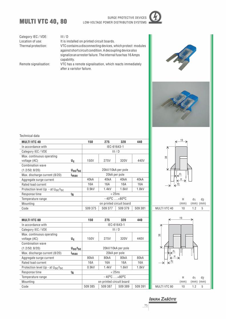
MULTI VTC 40
Uc
Imax
tA
In accordance withCategory IEC / VDEMax. continuous operating
(AC)
Max. discharge current (8/20)
Rated load current
Response timeTemperature rangeMountingCode
voltageCombination wave(1.2/50; 8/20)
Aggregate surge current
Protection level Up - at Uoc/Isc
Uoc/Isc
MULTI VTC 80
Uc
Imax
tA
In accordance with
continuousvoltage
(1.2/50; 8/20)
Protection level Up - at Uoc/Isc
Category IEC / VDEMax. operating
(AC)Combination wave
Max. discharge current (8/20)Aggregate surge currentRated load current
Response timeTemperature rangeMountingCode
Uoc/Isc
150 275 320 440IEC-61643-1
III / D
150V 275V 320V 440V
20kV/10
0.9kV 1.4kV 1.6kV 1.8kV< 25ns
on printed circuit board
kA per pole20kA per pole
40kA 40kA 40kA 40kA16A 16A 16A 16A
- 40 C ….+80 C
509 375 509 377 509 379 509 381
o o
150 275 320 440IEC-61643-1
III / D
150V 275V 320V 440V
0.9kV 1.4kV 1.6kV 1.8kV< 25ns
on printed circuit board
20kV/10kA per pole20kA per pole
80kA 80kA 80kA 80kA16A 16A 16A 16A
- 40 C ….+80 C
509 385 509 387 509 389 509 391
o o
Category IEC / VDE:Location of use: It is installed on printed circuit boards.Thermal protection: VTC contains a disconnecting devices, which protect modules
against short circuit condition. A decoupling device alsosignalize an arrester failure. The internal fuse has 16 Ampscapability.
Remote signalisation: VTC has a remote signalisation, which reacts immediatelyafter a failure.
III / D
varistor
MULTI VTC 40, 80MULTI VTC 40, 80SURGE PROTECTIVE DEVICES
LOW-VOLTAGE POWER DISTRIBUTION SYSTEMS
Technical data
38
38
19
H
H
19
H(mm)
H(mm)
d1(mm)
d1(mm)
d2(mm)
d2(mm)
MULTI VTC 80 10 1.2 5
MULTI VTC 40 10 1.2 5
d2
d2
d1
d1
75

VTC 15
Uc
Imax
tA
In accordance withCategory IEC / VDEMax. continuous operating
(AC)
Max. discharge current (8/20)Rated load current
Response timeTemperature rangeMountingCode
voltageCombination wave(1.2/50; 8/20)
Protection level Up - at Uoc/Isc
Uoc/Isc
VTC 20
Uc
Imax
tA
In accordance with
continuousvoltage
(1.2/50; 8/20)
Protection level Up - at Uoc/Isc
Category IEC / VDEMax. operating
(AC)Combination wave
Max. discharge current (8/20)Rated load current
Response timeTemperature rangeMountingCode
Uoc/Isc
150 275 320 440IEC-61643-1
III / D
150V 275V 320V 440V
15kV/7.5
0.9kV 1.4kV 1.6kV 1.8kV< 25ns
on printed circuit board
kA 15kV/7.5kA 15kV/7.5kA 15kV/7.5kA15kA 15kA 15kA 15kA16A 16A 16A 16A
- 40 C ….+80 C
509 355 509 357 509 359 509 361
o o
150 275 320 440IEC-61643-1
III / D
150V 275V 320V 440V
20kV/10
0.9kV 1.4kV 1.6kV 1.8kV< 25ns
on printed circuit board
kA 20kV/10kA 20kV/10kA 20kV/10kA20kA 20kA 20kA 20kA16A 16A 16A 16A
- 40 C ….+80 C
509 365 509 367 509 369 509 371
o o
Category IEC / VDE:Location of use: It is installed on printed circuit boards.Thermal protection: VTC contains a disconnecting device, which protects a module
against short circuit condition. A decoupling device alsosignalizes an arrester failure. The internal fuse has 16 Ampscapability.
Remote signalisation: VTC has a remote signalisation, which reacts immediatelyafter a failure.
III / D
varistor
VTC 15, 20VTC 15, 20
Technical data
H(mm)
H(mm)
(mm)
(mm)
VTC 15 10 0.8
VTC 20 10 0.8
38
19
H
28
H
SURGE PROTECTIVE DEVICES
LOW-VOLTAGE POWER DISTRIBUTION SYSTEMS
76

VTC 12
Uc
Imax
tA
In accordance with
continuousvoltage
(1.2/50; 8/20)
Protection level Up - at Uoc/Isc
Category IEC / VDEMax. operating
(AC)Combination wave
Max. discharge current (8/20)Rated load current
Response timeTemperature rangeMountingCode
Uoc/Isc
150 275 320 440IEC-61643-1
III / D
150V 275V 320V 440V
12kV/6
0.9kV 1.4kV 1.6kV 1.8kV< 25ns
on printed circuit board
kA 12kV/6kA 12kV/6kA 12kV/6kA12kA 12kA 12kA 12kA16A 16A 16A 16A
- 40 C ….+80 C
509 345 509 347 509 349 509 351
o o
23
22
H
H(mm) (mm)
VTC 12 10 0.8
VTC 10
Uc
Imax
tA
In accordance with
continuousvoltage
(1.2/50; 8/20)
Protection level Up - at Uoc/Isc
Category IEC / VDEMax. operating
(AC)Combination wave
Max. discharge current (8/20)Rated load current
Response timeTemperature rangeMountingCode 7,5mm
10mm
Uoc/Isc
150 275 320 440IEC-61643-1
III / D
150V 275V 320V 440V
10kV/5
0.9kV 1.4kV 1.6kV 1.8kV< 25ns
on printed circuit board
kA 10kV/5kA 10kV/5kA 10kV/5kA10kA 10kA 10kA 10kA16A 16A 16A 16A
- 40 C ….+80 C
509 301 509 303 509 305 509 307509 309 509 311 509 313 509 315
o o
23
22
Category IEC / VDE:Location of use: It is installed on printed circuit boards.Thermal protection: VTC contains a disconnecting device, which protects a module
against short circuit condition. A decoupling device alsosignalizes an arrester failure. The internal fuse has 16 Ampscapability.
Remote signalisation: VTC has a remote signalisation, which reacts immediatelyafter a failure.
III / D
varistor
VTC 10, 12VTC 10, 12
H
H(mm) (mm)
VTC 10 7.5, 10 0.8
SURGE PROTECTIVE DEVICES
LOW-VOLTAGE POWER DISTRIBUTION SYSTEMS
77

VTC 6
Uc
Imax
tA
In accordance withCategory IEC / VDEMax. continuous operating
(AC)
Max. discharge current (8/20)Rated load current
Response timeTemperature rangeMountingCode 7,5mm
10mm
voltageCombination wave(1.2/50; 8/20)
Protection level Up - at Uoc/Isc
Uoc/Isc
150 275 320 440IEC-61643-1
III / D
150V 275V 320V 440V
6kV/
0.9kV 1.4kV 1.6kV 1.8kV< 25ns
on printed circuit board
3kA 6kV/3kA 6kV/3kA 6kV/3kA6kA 6kA 6kA 6kA16A 16A 16A 16A
- 40 C ….+80 C
509 317 509 319 509 321 509 323509 325 509 327 509 329 509 331
o o
22
H
H(mm) (mm)
VTC 6 7.5, 10 0.8
VTC 4
Uc
Imax
tA
In accordance withCategory IEC / VDEMax. continuous operating
(AC)
Max. discharge current (8/20)Rated load current
Response timeTemperature rangeMountingCode
voltageCombination wave(1.2/50; 8/20)
Protection level Up - at Uoc/Isc
Uoc/Isc
150 275 320 440IEC-61643-1
III / D
150V 275V 320V 440V
4kV/2
0.9kV 1.4kV 1.6kV 1.8kV< 25ns
on printed circuit board
kA 4kV/2kA 4kV/2kA 4kV/2kA4kA 4kA 4kA 4kA16A 16A 16A 16A
- 40 C ….+80 C
509 335 509 337 509 339 509 341
o o
19
Category IEC / VDE:Location of use: It is installed on printed circuit boards.Thermal protection: VTC contains a disconnecting device, which protects a module
against short circuit condition. A decoupling device alsosignalizes an arrester failure. The internal fuse has 16 Ampscapability.
Remote signalisation: VTC has a remote signalisation, which reacts immediatelyafter a failure.
III / D
varistor
VTC 4, 6VTC 4, 6
Technical data
H
H(mm) (mm)
VTC 4 10 0.8
SURGE PROTECTIVE DEVICES
LOW-VOLTAGE POWER DISTRIBUTION SYSTEMS
78

>63A gL
63A gLmin. recommendedcross section 6 mm2
Selection of back-up fuse
Type
UcUoc
Imax
tA
In accordance withCategory IEC / VDEMax. continuous operating
(AC/DC)Combination wave(1.2/50-8/20)Max. discharge current (8/20)
Protection level Up - atFollow currentResponse time
Thermal decoupler
Back-up fuse (if mains > 63A)Short-circuit withstandTemperature rangeCross-section of connection wireMountingDegree of protectionCasing material
Code
voltage
Uoc/Isc
Weight per unit
/Isc
If
Current peak value(10/350)Specific energyCharge
Dimensions
Ipeak
Residual current at Uc
Torque
IPE
MPE-ZE50MPE-ZE50
Technical data
Category IEC / VDE: III / DLocation of use: It is installed as close as possible to a protected device.Protection againstthermal runaway: disconnecting device, which optically signalizes a varistor
failure.Remote signalisation: reacts immediately after a varistor failure
MPE-ZE50 is intended for protection against indirect lightning strikes. As a protective element avaristors are used.It is intended for protection in zones 2-3 next to a protected device.
SURGE PROTECTIVE DEVICES
LOW-VOLTAGE POWER DISTRIBUTION SYSTEMS
MPE-ZE50320
IEC-61643-1III / D
320/420V
5kA
1.5kVNO
< 100ns/
YES/
35A gL10kA / 50Hz
- 40 C ….+80 Cmulti-strand 2.5mm
IP 20thin plate (metal)
/
5kV/2.5kA
o o
2
///
/121 207
L N
PE
79

PRO AQTEC 25/xxx150 275 320 440
IEC-61643-11I, II / B, C
150/200V 275/350V 320/420V 440/580V10kA25kA
0.9kV 1.2kV 1.3kV 1.6kV
NO< 25ns< 2mAYES
max. 3.5NmNO
25kA / 50Hz- 40 C ….+80 C
M8multi- 6 mm
10kA 10kA 10kA25kA 25kA 25kA
strand
o o
2
/ / / // / / // / / /
/
Category IEC / VDE: II / CLocation of use: It is installed on overhead lines.Protection againstthermal runaway: PROTEC AQ contains a decoupling device, which protects a
module against short circuit condition.Also other Uc voltages are available on request.
L/N
PE
PRO AQTECPRO AQTEC
o 47
M 8
7344
19
Type
UcInImax
tA
In accordance withCategory IEC / VDEMax. continuous operating
(AC/DC)Nominal discharge current (8/20)Max. discharge current (8/20)
Protection level Up - at In (8/20)
Follow currentResponse timeResidual current at UcThermal decoupler
Back-up fuseShort-circuit withstandTemperature rangeCross-section of connection wire L/N
PEMounting
Casing material
Code
voltage
Torque
Weight per unit
Packaging - single / Dimensions
I
I
f
PE
Current peak value (10/350)Specific energyCharge
Dimensions
Ipeak
- at Iimp (10/350)
Degree of protection
Additional data for TECPRO AQRemote signalisationSwitching capability- Cross-section of connection wireTorqueWeight per unitCode
Technical data
Connection clamp fornon insulated conductors
PSNCode: 509 503
Connection clamp forinsulated conductors
PSICode: 509 505
outdors
thermoplastic; extinguishing degree UL 94 V-O
105g509 017 509 019 509 021 509 023
105mm x 54mm x 50mm
/
/
/////
/ / / /
SURGE PROTECTIVE DEVICES
LOW-VOLTAGE POWER DISTRIBUTION SYSTEMS
Fixing hookCode: 509 501
500 mm
Mounting
80
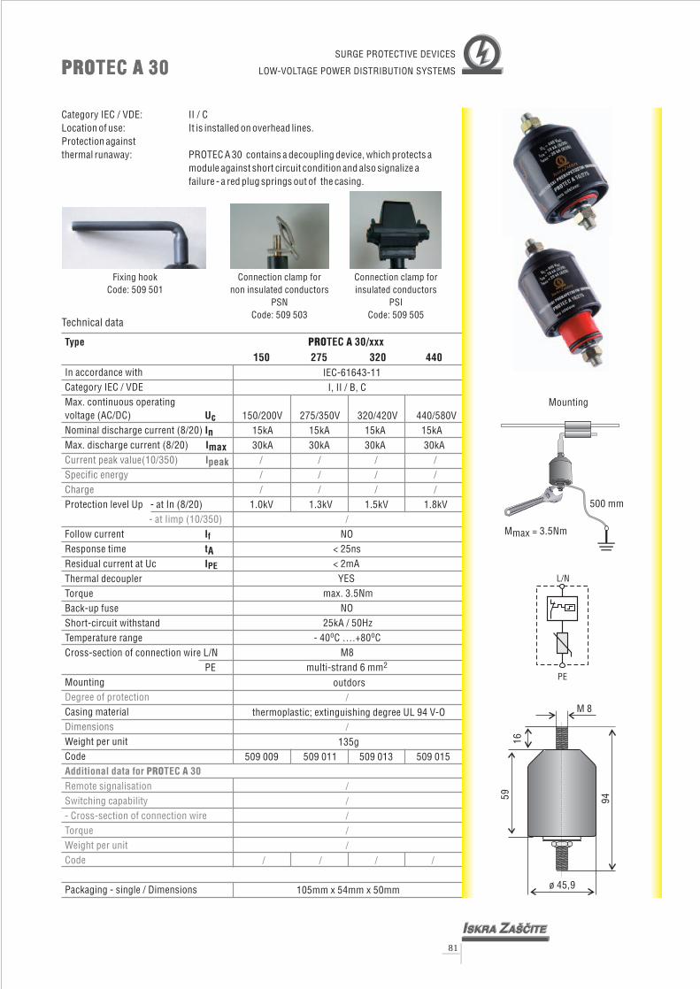
PRO ATEC 30/xxx150 275 320 440
IEC-61643-11I, II / B, C
150/200V 275/350V 320/420V 440/580V15kA30kA 3
1.0kV 1.3kV 1.5kV 1.8kV
NO< 25ns< 2mAYES
max. 3.5NmNO
25kA / 50Hz- 40 C ….+80 C
M8multi- 6 mm
15kA 15kA 15kA0kA 30kA 30kA
strand
o o
2
/ / / // / / // / / /
/
Category IEC / VDE: II / CLocation of use: It is installed on overhead lines.Protection againstthermal runaway: PROTEC A 30 contains a decoupling device, which protects a
module against short circuit condition and also signalize afailure - a red plug springs out of the casing.
L/N
PE
PRO ATEC 30PRO ATEC 30
Type
UcInImax
tA
In accordance withCategory IEC / VDEMax. continuous operating
(AC/DC)Nominal discharge current (8/20)Max. discharge current (8/20)
Protection level Up - at In (8/20)
Follow currentResponse timeResidual current at UcThermal decoupler
Back-up fuseShort-circuit withstandTemperature rangeCross-section of connection wire L/N
PEMounting
Casing material
Code
voltage
Torque
Weight per unit
Packaging - single / Dimensions
I
I
f
PE
Current peak value(10/350)Specific energyCharge
Dimensions
Ipeak
- at Iimp (10/350)
Degree of protection
Additional data for TEC 30PRO ARemote signalisationSwitching capability- Cross-section of connection wireTorqueWeight per unitCode
Technical data
Connection clamp fornon insulated conductors
PSNCode: 509 503
Connection clamp forinsulated conductors
PSICode: 509 505
outdors
thermoplastic; extinguishing degree UL 94 V-O
135g509 009 509 011 509 013 509 015
105mm x 54mm x 50mm
/
/
/////
/ / / /
SURGE PROTECTIVE DEVICES
LOW-VOLTAGE POWER DISTRIBUTION SYSTEMS
Fixing hookCode: 509 501
o 45,9
M 8
945916
500 mm
Mounting
Mmax = 3.5Nm
81

PRO ATEC 20/xxx150 275 320 440
IEC-61643-11I, II / B, C
150/200V 275/350V 320/420V 440/580V10kA20kA
0.9kV 1.2kV 1.3kV 1.6kV
NO< 25ns< 2mAYES
max. 3.5NmNO
25kA / 50Hz- 40 C ….+80 C
M8multi- 6 mm
10kA 10kA 10kA20kA 20kA 20kA
strand
o o
2
/ / / // / / // / / /
/
Category IEC / VDE: II / CLocation of use: It is installed on overhead lines.Protection againstthermal runaway: PROTEC A 20 contains a decoupling device, which protects a
module against short circuit condition and also signalize afailure - a red plug springs out of the casing.
L/N
PE
PRO ATEC 20PRO ATEC 20
Type
UcInImax
tA
In accordance withCategory IEC / VDEMax. continuous operating
(AC/DC)Nominal discharge current (8/20)Max. discharge current (8/20)
Protection level Up - at In (8/20)
Follow currentResponse timeResidual current at UcThermal decoupler
Back-up fuseShort-circuit withstandTemperature rangeCross-section of connection wire L/N
PEMounting
Casing material
Code
voltage
Torque
Weight per unit
Packaging - single / Dimensions
I
I
f
PE
Current peak value (10/350)Specific energyCharge
Dimensions
Ipeak
- at Iimp (10/350)
Degree of protection
Additional data for TEC 20PRO ARemote signalisationSwitching capability- Cross-section of connection wireTorqueWeight per unitCode
Technical data
Connection clamp fornon insulated conductors
PSNCode: 509 503
Connection clamp forinsulated conductors
PSICode: 509 505
outdors
thermoplastic; extinguishing degree UL 94 V-O
135g509 001 509 003 509 005 509 007
105mm x 54mm x 50mm
/
/
/////
/ / / /
SURGE PROTECTIVE DEVICES
LOW-VOLTAGE POWER DISTRIBUTION SYSTEMS
Fixing hookCode: 509 501
o 45,9
M 8
945916
500 mm
Mounting
Mmax = 3.5Nm
82

PROSPARK 2.5
o 45,9
M 8
9459
16
PROSPARK1 2.5 10
1kV 2.5kV 10kV2kV 5kV 15kV
100kA 100kA 50kAthermoplastic U-O
-30 C ... +80 C59 x 45.9mm
< 10Gohms < 10Gohms < 10Gohms501 201
o o
501 203 501 205
The PROSPARK is intended for preventing earth potential differences, in case of lightningcurrents, between equipment and structure (metal pylons, cables, tubes) which areconnected with different earthing points. When its sparkover voltage has been attained, theequipotential spark gap causes the equilisation of earth potentials and therefore preventsdamage. The PROSPARK is completely sealed and can be used for heawy duty conditions.
PROSPARKPROSPARK
Type
In
ACsparkover voltage 50HzImpulse sparkover voltage (1.2/50)Nominal discharge current (8/20)Casing materialTemperature rangeDimensionsInsulation resistanceCode
Technical data
EQUIPOTENTIAL SPARK GAP
83

Type
Protective element Gas Discharge TubeSpark over voltage 350 V +/-15% (at 100 V/s)
Insulation Resistance (100 V) >3 G
Capacitance (1MHz) < 10 pF
Connections 450 mm of 16 mm (17" of 5AWG) conductorTemperature range –10 °C to +60 °C ( –14 °F to +140 °F)
EPZ 100
Max. Discharge Current 100 kA (8/20 s)
Voltage Protection Level 1000 V (at 1 kV/ s)
Enclosure waterproof, insulated metal tubeWarranty 5 yearsDimensions (central body) cca: D=30 mm, l=150 mmWeight cca 0,5 kgCode 509 509
Imax
Up2
�
�
�
Technical data
LIGHTNING EQUIPOTENTIAL BONDING
Transient earth clamp and insulated joint protector EPZ 100kA and EPZ 100kA-C (coated)Properties:- High peak current capability - long service life- Weatherproof enclosure - suitable for direct embedding- Explosion proof - suitable for use on gas pipelines- No exhaust
Application:Transient earth clamp is the surge protective element which is convenient for applicationeverywhere, where the needs for potential equalization are necessary.- galvanic separation of different grounding system- eliminating of earth loops
Galvanic separation of differentgrounding system
EPZ 100EPZ 100
84

Type
UcInImax
tA
In accordance withCategory IEC / VDEMax. continuous operating
(AC/DC)Nominal discharge current (8/20)Max. discharge current (8/20)
Protection level Up - at In (8/20)
Follow currentResponse time
Thermal decouplerBack-up fuse (if mains > 160 A)Short-circuit withstandTemperature rangeCode
voltage
Residual current at Uc
Packaging - single / Dimensions
I
I
f
PE
Current peak value (10/350)Specific energyCharge
- at Iimp (10/350)
Ipeak
PRO CTEC 20/CHPRO CTEC 20/CH
PRO C 20TEC /CH150 275 320 440
IEC-61643-1II / C
150/200V 275/350V 320/420V 440/580V10kA 1020kA 20kA 20kA 20kA
/
0.7kV 1.4kV 1.6kV 2.2kV
NO< 25ns
< 2.5mAYES
160A gL25kA / 50Hz
- 40 C ….+80 C501 409 501 411 501 413 501 415
kA 10kA 10kA
/ / // / / /
/ / / /
/ / / /
108mm x 74mm x 24mm
o o
Technical data
Category IEC / VDE: II / CLocation of use: It is installed in the sub-distribution panel (SB) or as close as
possible to a protected device.
PROTEC C 20/CH is intended for protection againstinduced surges. As a protective element a varistor is used. Therefore, also at this
module no following current (IF) is present. It has to be co-ordinated with lightning arresters.
partial direct and indirect atmosphericdischarges and
>160A gL
160A gLmin. recommendedcross section 16 mm2
Selection of back-up fuse
SURGE PROTECTIVE DEVICES
LOW-VOLTAGE POWER DISTRIBUTION SYSTEMS
22
PE
L/N
85

Type
UcInImax
tA
In accordance withCategory IEC / VDEMax. continuous operating
(AC/DC)Nominal discharge current (8/20)Max. discharge current (8/20)
Protection level Up - at In (8/20)
Follow currentResponse time
Thermal decouplerBack-up fuse (if mains > 160 A)Short-circuit withstandTemperature rangeCode
voltage
Residual current at Uc
Packaging - single / Dimensions
I
I
f
PE
Current peak value (10/350)Specific energyCharge
- at Iimp (10/350)
Ipeak
PRO CTEC 10/CHPRO CTEC 10/CH
PRO C 10TEC /CH150 275 320 440
IEC-61643-1II / C
150/200V 275/350V 320/420V 440/580V5kA 5
10kA 10kA 10kA 10kA/
0.7kV 1.4kV 1.6kV 2.2kV
NO< 25ns< 2.5mA
YES160A gL
25kA / 50Hz- 40 C ….+80 C
501 401 501 403 501 405 501 407
kA 5kA 5kA
/ / // / / /
/ / / /
/ / / /
108mm x 74mm x 24mm
o o
Technical data
Category IEC / VDE: II / CLocation of use: It is installed in the sub-distribution panel (SB) or as close as
possible to a protected device.
PROTEC C 10/CH is intended for protection againstinduced surges. As a protective element a varistor is used. Therefore, also at this
module no following current (IF) is present. It has to be co-ordinated with lightning arresters.
partial direct and indirect atmosphericdischarges and
>160A gL
160A gLmin. recommendedcross section 16 mm2
Selection of back-up fuse
SURGE PROTECTIVE DEVICES
LOW-VOLTAGE POWER DISTRIBUTION SYSTEMS
14
PE
L/N
86

PRO S1/22VAROPRO S1/22VARO
Category IEC / VDE: I, II / B,CMain distribution board (MB)Location of use:
PROVARO S1/22 is an overvoltage arrester for protection against partial direct and indirectatmospheric discharges. It is used as a galvanic separation between N-PE conductor in 1+1 or 3+1systems (TT network).PROTVARO S1/22 is intended for protection in zones 0 - 1.A
Type
UcInImaxIpeak
tA
In accordance withCategory IEC / VDEMax. continuous operating
(AC/DC)Nominal discharge current (8/20)Max. discharge current (8/20)Current peak value (10/350)Specific energyChargeProtection level Up
- at (1.2/50)Follow currentResponse time
Temperature rangeCode
voltage
Packaging - single / Dimensions
If
- at In (8/20)
Thermal decouplerBack-up fuseShort-circuit withstand
Residual current at Uc IPE
PRO S1/22VAROIEC-61643-1
kA
108mm x 76mm x 41mm
I, II / B, C
255V50kA
100kA50
625 kJ/
25As/
< 4kV100A
100ns////
- 40 C ….+80 C501 419
�
RMS
o o
Technical data
SURGE PROTECTIVE DEVICES
LOW-VOLTAGE POWER DISTRIBUTION SYSTEMS
22
87

PRO S1/14VAROPRO S1/14VARO
Category IEC / VDE: I, II / B,CMain distribution board (MB)Location of use:
PROVARO S1/14 is an overvoltage arrester for protection against partial direct and indirectatmospheric discharges. It is used as a galvanic separation between N-PE conductor in 1+1 or 3+1systems (TT network).PROTVARO S1/14 is intended for protection in zones 0 - 1.A
Type
UcInImaxIpeak
tA
In accordance withCategory IEC / VDEMax. continuous operating
(AC/DC)Nominal discharge current (8/20)Max. discharge current (8/20)Current peak value (10/350)Specific energyChargeProtection level Up
- at (1.2/50)Follow currentResponse time
Temperature rangeCode
voltage
Torque
Packaging - single / Dimensions
If
- at In (8/20)
Thermal decoupler
Back-up fuseShort-circuit withstand
Residual current at Uc IPE
PRO S1/14VAROIEC-61643-1
kA
108mm x 76mm x 41mm
I, II / B, C
255V20kA40kA20
100 KJ/
10As/
< 4kV100A
100ns//
max. 4.5Nm//
- 40 C ….+80 C501 417
�
RMS
o o
Technical data
88
SURGE PROTECTIVE DEVICES
LOW-VOLTAGE POWER DISTRIBUTION SYSTEMS
14
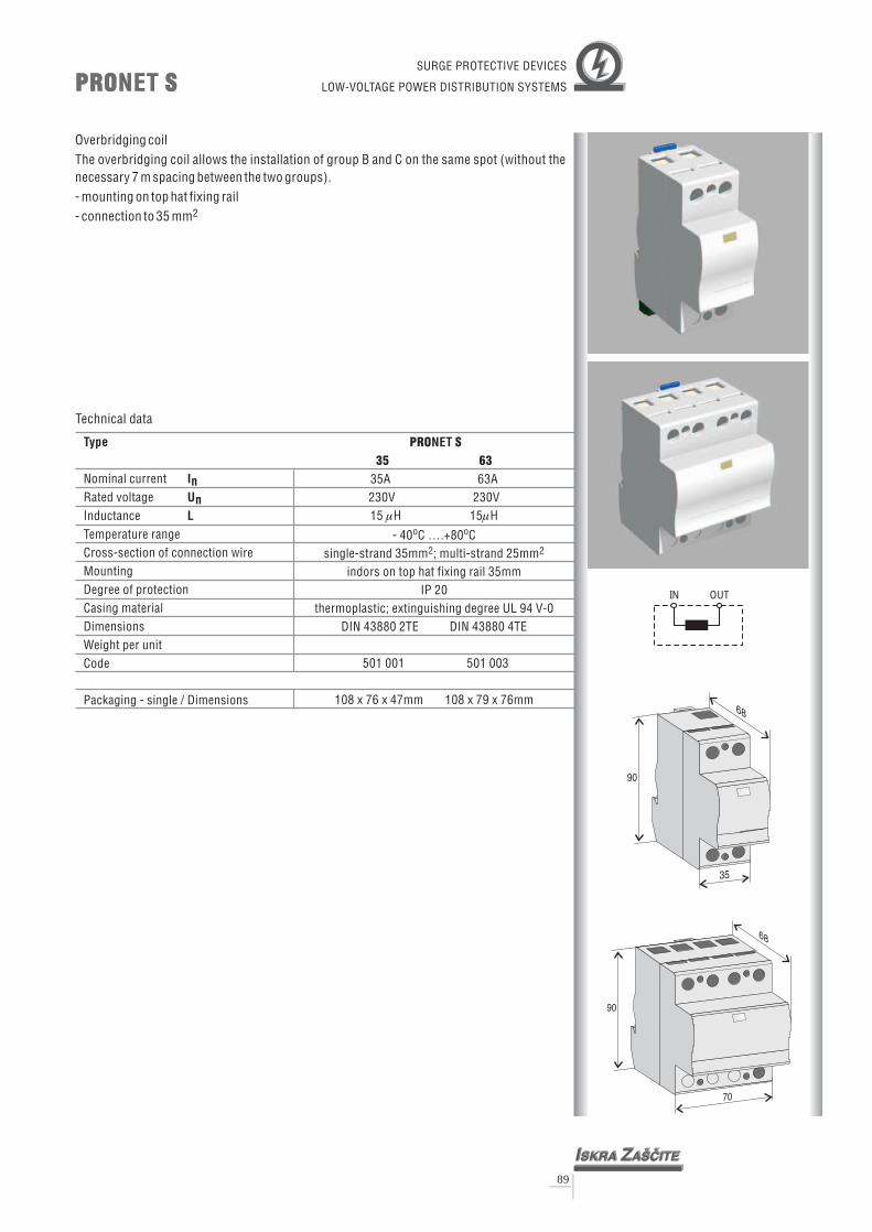
70
68
90
35
68
90
PRO SNETPRO SNET
Overbridging coilThe overbridging coil allows the installation of group B and C on the same spot (without thenecessary 7 m spacing between the two groups).- mounting on top hat fixing rail- connection to 35 mm2
OUTIN
Type
In
L
Nominal currentRated voltageInductanceTemperature rangeCross-section of connection wireMountingDegree of protectionCasing materialDimensions
Code
Un
Weight per unit
Packaging - single / Dimensions
PRO S35 63
NET
35A 63A230V 230V15 H 15 H
- 40 C ….+80 C
indors on top hat fixing rail 35mmIP 20
thermoplastic; extinguishing degreeDIN 43880 2TE
501 001 501 003
o o
single-strand 35mm ; multi-strand 25mm
UL 94 V-0DIN 43880 4TE
108 x 76 x 47mm 108 x 79 x 76mm
2 2
� �
Technical data
89
SURGE PROTECTIVE DEVICES
LOW-VOLTAGE POWER DISTRIBUTION SYSTEMS
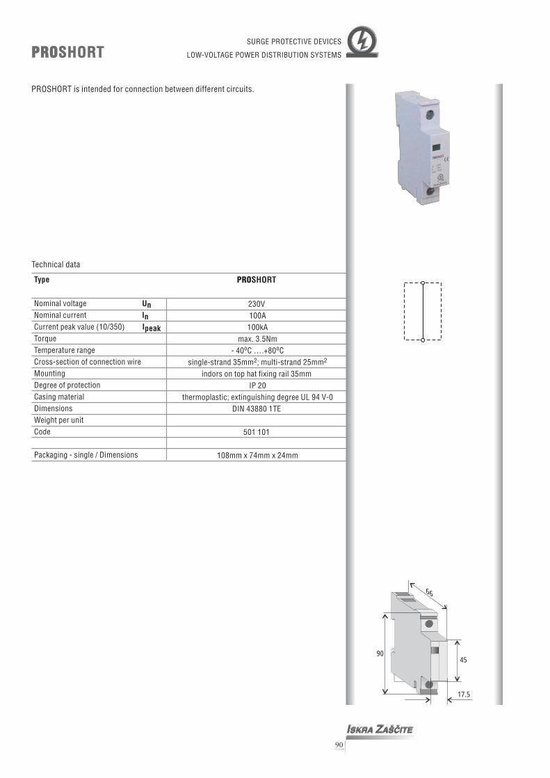
90
PROSHORTPROSHORT
Type
UnInIpeak
Nominal voltageNominal currentCurrent peak value (10/350)
Temperature rangeCross-section of connection wireMountingDegree of protectionCasing materialDimensions
Code
Torque
Weight per unit
Packaging - single / Dimensions
PROSHORT
230V100A100kA
max. 3.5Nm- 40 C ….+80 C
indors on top hat fixing rail 35mmIP 20
thermoplastic; extinguishing degree V-0DIN 43880 1TE
501 101
o o
single-strand 35mm ; multi-strand 25mm
UL 94
108mm x 74mm x 24mm
2 2
Technical data
SURGE PROTECTIVE DEVICES
LOW-VOLTAGE POWER DISTRIBUTION SYSTEMS
PROSHORT is intended for connection between different circuits.
66
4590
17.5
I ZSKRA A[^ITE
Un = 230 V
In = 100 A
Ipeak = 100 kA
PROSHORT

BUSBARS - Modular wiring systems
Single phase busbars
Busbars are used for bonding conductors, according to what type of system is used andnumber of connecting poles needed.
Type PRObar 1-2
No. of poles 2
Busbar cross section 16mm2
Code 501 301
Type PRObar 1-3
No. of poles 3
Busbar cross section 16mm2
Code 501 303
Type PRObar 1-4
No. of poles 4
Busbar cross section 16mm2
Code 501 305
Type PRObar 1-5
No. of poles 5
Busbar cross section 16mm2
Code 501 307
Type PRObar 1-6
No. of poles 6
Busbar cross section 16mm2
Code 501 309
Type PRObar 1-7
No. of poles 7
Busbar cross section 16mm2
Code 501 311
Type PRObar 1-8
No. of poles 8
Busbar cross section 16mm2
Code 501 313
Type PRObar 1-9
No. of poles 9
Busbar cross section 16mm2
Code 501 315
91
SURGE PROTECTIVE DEVICES
LOW-VOLTAGE POWER DISTRIBUTION SYSTEMSACCESSORIESACCESSORIES

Two phase busbars
Three phase busbars
Type PRObar 2-8
No. of poles 8
Busbar cross section 16mm2
Code 501 317
Type PRObar 3-6
No. of poles 6
Busbar cross section 16mm2
Code 501 319
Type PRObar 3-8
No. of poles 8
Busbar cross section 16mm2
Code 501 321
92
SURGE PROTECTIVE DEVICES
LOW-VOLTAGE POWER DISTRIBUTION SYSTEMSACCESSORIESACCESSORIES


EROZ MRP
Power distribution box with protection for base radio stations
EROZ MRD
Power distribution box with protection for telephone exchanges
EROZ 4/5 (16A)
Power distribution box with protection for small telephone exchanges
DZEO 2/2 (35A)
Two stage overvoltage protection box for use in power supply systems
SURGE PROTECTIVE DEVICES
LOW-VOLTAGE POWER DISTRIBUTION SYSTEMSDistribution BoxesDistribution Boxes
94

IGSA-1000IGSA-1000
Power Mains Voltage 220/240V, 50Hz, 26VA max.Single Shot Pulse, Voltage Shape 1.2/50 s
Ramping Voltage 1.000V/ s
Leading Edge Polarity positiveMaximum Pulse Voltage 6kVdcLED 3.5 Display 0.00 to 6.00 kVolts, with <1% accuracy,Green LED Indicator “Ready” stateRed LED Indicator “Ramp” stateOutput Voltage Setting 10 turn potentiometerYellow LED IndicatorGreen Coloured Push-Button-SwitchBlack Coloured Push-Button-Switch Start of Ramping VoltageOutput Terminals black for minus and
red for positive high voltageOperating Temperature range 10 C to 35 CStorage Temperature range 0 C to 60 CDimensions 330 x 85 x 250 mm (w x h x d),Weight 4.2 kg.
in combination withSetting Output Voltage
o o
o o
�
�
The Ramp Generator IGSA-1000 is primarily intended for the testing of elements used in surge voltageprotection systems and modules, such as Gas Surge Arrestors, Carbon Blocks, Spark Gaps, Varistors, ZenerDiodes, Transorb Diodes, Hybrid Circuits, etc. This generator gives a pulse of waveshape 1.2s/50s, with a1.000V/s ramp, while the voltage breakdown of the element, under test, is shown on a 3.5 digit LED display.The instrument complies to norms and standards specified by CCITT, IEEE, ANSI, IEC, etc.It can be used for laboratory and field use, as well as in a production environment, for quality controlpurposes. The construction of the instrument is robust, with an Aluminium, mild steel and plastic housing.
Technical specifications
The Ramp Generator HVGSA-100 is primarily intended for the testing of elements used in surge voltageprotection systems and modules, such as Gas Surge Arrestors, Carbon Blocks, Spark Gaps, Varistors, ZenerDiodes, Transorb Diodes, Hybrid Circuits, etc. It outputs a voltage rising at 100V/s, to a maximum of 8kV,while the voltage breakdown of the element under test is shown on a 4.5 digit LED display. The Current isshown on a 3.5 LED display. The instrument complies to norms and standards specified by CCITT, IEEE,ANSI, IEC, etc.It can be used for laboratory and field use, as well as in a production environment, for quality controlpurposes. The construction of the instrument is robust, with an Aluminium, and mild steel housing.
Technical specifications
Power Mains Voltage 220/240V, 50Hz, 40VA max.,Ramping Voltage 100V/sLeading Edge Polarity positiveMaximum Output Voltage 8kVdc4.5 LED Display for Voltage 0 to 8000 Volts, with <1% accuracy3.5 LED Display for Current 0.00 to 5.00mA, with <1% accuracyVoltage and Current are Held at Maximum Breakdown Values, on Completion of CycleSingle LED Indicator “Ready” green
“Ramp” redPush-Button-Switch Start of Ramping Voltage
StopTwo Position Switch for Selection of Maximum Currents: 1mA and 5mAOutput Terminals black for minus
red for positive high voltageOutput Terminals are Short Circuit ProofAfter Completion of Cycle, Output Terminals are Short Circuited, for Safety Purposes,Optional Communication port with PCOperating Temperature range 10 C to 35 C,Storage Temperature range 0 C to 60 C,Dimensions 240 x 165 x 300 mm (w x h x d),Weight 4.6 kg.
of Ramping Voltage
o o
o o
HVGSA-100HVGSA-100SPD TESTING INSTRUMENT
95

Testing services according to:
ISO, IEC - International standards
EN - European standards
LVD (Low Voltage Directive)
National standards (SIST, ÖVE, VDE, etc.)
Testing services for the following product:
Surge Protective Devices (SPDs)
Fuses
Relays
Components and materials
Electrical installations
Test and measurement equipment:
Short-circuit current testing for short periods up to 1200 V, 150 A
Environmental tests:
Climatic chambers
IP-code testing
Lightning Impulse Voltage tests:
Surge generator 10/700 s up to 10 kV
Lightning Impulse Current tests:
Current generator 4/10 up to 80 kA (Shunt 0.5 m )
Current generator 8/20 up to 200 kA (Pearson 1426)
Current generator 10/350 up to 100 kA (Pearson 1426)
Current generator 10/1000 up to 1 kA (Shunt 20 m )
Current generator 10/2000 up to 1 kA (Shunt 20 m )
Hybrid surges tests:
Hybrid generator 1.2/50 8/20 , 8 kV 4 kA (Zi= 2 )
Various other lightning tests upon request
s
s
s
s
s
s s
�
�
�
�
�
�
� �
�
�
�
�
96
Introduction:HV Laboratory in Iskra Za{~ite has beenestablished since 2000 with the opening of ournew Current Strike Crowbar Generator (TUG-200) as the non-profit inside-pendent body forthe purpose of test ing and researchdevelopment of our new SPD (Surge ProtectiveDevice) products. We are also open forcarrying the tests for foreign manufacturersand utilities according to the Internationalstandards or to providing the best services tomeet clients' needs.
High Voltage (HV) LaboratoryHigh Voltage (HV) Laboratory


![Experimental studies for surge voltage response of a power ...arpnjournals.com/jeas/research_papers/rp_2010/jeas_1110_419.pdfwinding [5-6]. The voltage distribution along the length](https://img.dokumen.tips/doc/110x75/5f21d3cce65f4e57bf44a4b5/experimental-studies-for-surge-voltage-response-of-a-power-winding-5-6-the.jpg)