Embed Size (px)
Citation preview
Red catalogue numbers : New products
cex-EP3
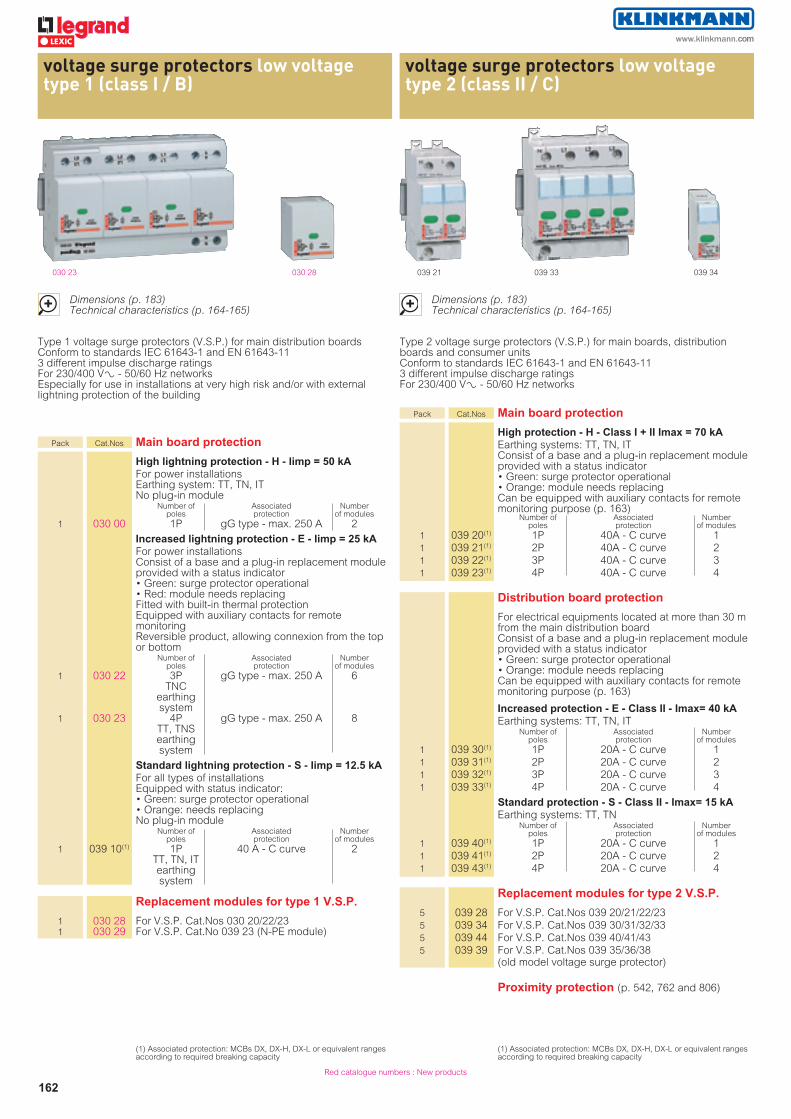
voltage surge protectors low voltage type 1 (class I / B)
voltage surge protectors low voltage type 2 (class II / C)
162
039 33030 28 039 21030 23
Type 1 voltage surge protectors (V.S.P.) for main distribution boards Conform to standards IEC 61643-1 and EN 61643-11 3 different impulse discharge ratings For 230/400 VA - 50/60 Hz networks Especially for use in installations at very high risk and/or with external lightning protection of the building
Type 2 voltage surge protectors (V.S.P.) for main boards, distribution boards and consumer units Conform to standards IEC 61643-1 and EN 61643-11 3 different impulse discharge ratings For 230/400 VA - 50/60 Hz networks
Pack Cat.Nos Main board protection
High lightning protection - H - Iimp = 50 kA For power installations
Earthing system: TT, TN, IT No plug-in module
Number of Associated Number poles protection of modules 1 030 00 1P gG type - max. 250 A 2
Increased lightning protection - E - Iimp = 25 kA For power installations
Consist of a base and a plug-in replacement module provided with a status indicator • Green: surge protector operational • Red: module needs replacing Fitted with built-in thermal protection Equipped with auxiliary contacts for remote monitoring Reversible product, allowing connexion from the top or bottom
Number of Associated Number poles protection of modules 1 030 22 3P gG type - max. 250 A 6
TNC earthing system
1 030 23 4P gG type - max. 250 A 8 TT, TNS earthing system
Standard lightning protection - S - Iimp = 12.5 kA For all types of installations
Equipped with status indicator: • Green: surge protector operational • Orange: needs replacing No plug-in module
Number of Associated Number poles protection of modules 1 039 10(1) 1P 40 A - C curve 2
TT, TN, IT earthing system
Replacement modules for type 1 V.S.P.
1 030 28 For V.S.P. Cat.Nos 030 20/22/23 1 030 29 For V.S.P. Cat.No 039 23 (N-PE module)
(1) Associated protection: MCBs DX, DX-H, DX-L or equivalent ranges according to required breaking capacity
(1) Associated protection: MCBs DX, DX-H, DX-L or equivalent ranges according to required breaking capacity
Dimensions (p. 183)Technical characteristics (p. 164-165)
Dimensions (p. 183)Technical characteristics (p. 164-165)
039 34
Pack Cat.Nos Main board protection
High protection - H - Class I + II Imax = 70 kA Earthing systems: TT, TN, IT
Consist of a base and a plug-in replacement module provided with a status indicator • Green: surge protector operational • Orange: module needs replacing Can be equipped with auxiliary contacts for remote monitoring purpose (p. 163)
Number of Associated Number poles protection of modules 1 039 20(1) 1P 40A - C curve 1 1 039 21(1) 2P 40A - C curve 2 1 039 22(1) 3P 40A - C curve 3 1 039 23(1) 4P 40A - C curve 4
Distribution board protection
For electrical equipments located at more than 30 m from the main distribution board Consist of a base and a plug-in replacement module provided with a status indicator • Green: surge protector operational • Orange: module needs replacing Can be equipped with auxiliary contacts for remote monitoring purpose (p. 163)
Increased protection - E - Class II - Imax= 40 kA Earthing systems: TT, TN, IT Number of Associated Number poles protection of modules 1 039 30(1) 1P 20A - C curve 1 1 039 31(1) 2P 20A - C curve 2 1 039 32(1) 3P 20A - C curve 3 1 039 33(1) 4P 20A - C curve 4
Standard protection - S - Class II - Imax= 15 kA Earthing systems: TT, TN Number of Associated Number poles protection of modules 1 039 40(1) 1P 20A - C curve 1 1 039 41(1) 2P 20A - C curve 2 1 039 43(1) 4P 20A - C curve 4
Replacement modules for type 2 V.S.P.
5 039 28 For V.S.P. Cat.Nos 039 20/21/22/23 5 039 34 For V.S.P. Cat.Nos 039 30/31/32/33 5 039 44 For V.S.P. Cat.Nos 039 40/41/43 5 039 39 For V.S.P. Cat.Nos 039 35/36/38
(old model voltage surge protector)
Proximity protection (p. 542, 762 and 806)
www.klinkmann.com

cex-EP3
voltage surge protectors
163
voltage surge protectors for telephone lines and accessories for low voltage V.S.P.
Pack Cat.Nos Voltage surge protector for telephone lines and data networks
Reccommended for complete protection of installations already equipped with low voltage V.S.P. on power lines (standard IEC 60364) For protection of: telephone, fax, modem, etc., connected to the incoming telephone line, against overvoltages of atmospheric origin Installed in a distribution cabinet, especially the ELV/signal cabinet Cat.No 011 95 (please consult us), or terminal shield boxes 1 module (p. 187) Connected in series with the telephone line Provided with a status indicator • green: surge protector operational • orange: surge protector needs replacing Conform to standards EN 61643-21 and IEC 61643-21 Imax: 10 kA and In: 5 kA (8/20)
Un Up (V) (V)
1 038 28 Analogue (RTC and ADSL) 170 260 1 038 29 Digital (signal lines, current loops) 48 100
038 28 038 29
Dimensions (p. 183)Technical characteristics (p. 164-165)
n Protection against lightning effects
Lightning directly or indirectly generates the following effects:• thermal (blow-outs, fire)• electrodynamic (loosening of terminals)• rise in earth voltage (risk of electrocution)• overvoltages of several thousand volts and destructive induced currents (damage to electrical and electronic equipment, interruption of operation)Protection against the effects of lightning is based essentially on:• catching and discharging the current to earth• the use of voltage surge protectors• the passive protection of the installationPassive protection (poor, good) designates the part of the protection provided by the structure and the configuration of the installation itself (neutral earthing system, area, level of equipotentiality, etc.)
n Voltage surge protectors and regulation
Voltage surge protector enable:• protect sensitive devices against direct and indirect effects of lighning• to limit harmful consequences on person security• to insure the continuity of work
1 - Product standarts EN 61643-11 and IEC 61643-1Characterize voltage surge protectors in two main levels (types):
2 - Installation standards: IEC 60364 (or equivalent electric national standards)According to articles 443 and 534, the use of VSPs is required in new or renovated buildings in the following cases:• buildings equipped with lightning conductors: type 1 VSPs • buildings with overhead power supply in class AQ2 geographic zones (see map below: red zones): type 2 VSPs with In ≥ 5 kA• buildings with medical services or equipped with safety systems (fire, etc.) in class AQ2 geographic zones: type 2 VSPs with In ≥ 5 kAThe use of VSPs is also strongly recommended in mountain areas, close to reaches of water or dominating structures (buildings, trees, etc.), in the cases of line end installations or installations located less than 50 m from buildings equipped with lightning conductors(2)
When VSPs are present on the power circuit, it is strongly advised to install a VSP on the communication circuits (telephone or data lines…)
(2) Lightning conductors: external protection of buildings against direct lightning impacts
n Choice of the level lightning protection
0 - 12 - 45 - 910 - 1920 - 3940 - 5960 - 7980 - 99100 - 139140 - 200 +
The annual average of stormy days (Nk)
AQ2 areas : Nk > 25IEC 60364 : V.S.P. mandatory for installations supplied with overhead low voltage lines and located in AQ2 areas
Signalling auxiliaries for low voltage V.S.P.
With changeover microswitch 2 A - 250 V± Mounted onto the base of the surge protector (except Cat.No 039 10)
1 039 56 For 2-pole module V.S.P. 1 039 57 For 3-pole module V.S.P. 1 039 58 For 4-pole module V.S.P.
Decoupling inductors for low voltage V.S.P.
Enable coordination between 2 V.S.P. in the same board, when minimum distance to insure proper V.S.P. coordination can not be respected For multipole voltage surge protectors, each conductor (including the neutral conductor) must be equipped with one decoupling inductor
Number of modules
1 039 62 Module for circuit 35 A - 500 V± 2 1 039 63 Module for circuit 63 A - 500 V± 4
Proximity protection (p. 542, 762 and 806)
EN 61643-11 Type 1 (T1) Type 2 (T2)
IEC 61643-1 Class I (T1) Class II (T2)
VDE 0675-6(1) Class B Class C
Type of wave 10/350 µs 8/20 µs
Main characteristics Iimp (10/350) In (8/20) In, Imax
(1) German standard VDE replaced by European standard EN 61643-11
www.klinkmann.com

164 165
n Technical characteristics
Voltage surge protectors for power lines
Networks: 230/400 VA - 50/60 Hz Degree of protection: IP 20 Operating temperature: -10° C to +40° C Storage temperature: -20° C to +70° C
Voltage surge protectors for telephone lines
Degree of protection: IP 20 Operating temperature: -10° C to +40° C Storage temperature: -20° C to +70° C
n Installation
Voltage surge protectors cascading (multi-level protection)
Beyond the standards requirements:• the cost of the consequences of equipment unavailability,• the nature of the equipment to be protected (IT, electronics, etc.),• the situation of the buildings (proximity or not of a building equipped with a lightning conductor),• the power supply network…,are all situations that justify the installation of VSPs.However, the efficiency of protection against overvoltages cannot be optimally ensured with a single VSP.This is why Legrand recommends combining several VSPs in cascade with different protection levels, from the first panel as far as the device to be protected (proximity protection of sensitive devices).An installation will be all the more efficient if, beyond Class I and II VSPs, it comprises proximity VSPs (Class III) on sockets supplying sensitive devices (IT, electronic, etc.).
Associated protectionThe supply circuit of the VSP must be protected against short-circuits and overloads by its associated disconnector (MCB) in accordance with discrimination rules.TT earthing systems, and V.S.P.: V.S.P. always installed downstream a residual current device (RCD) (V.S.P. Cat.No 030 23 can be installed upstream RCDs if alloweed by local regulations)
Connection principles
For the voltage surge protector to perform it’s function as well as possible, it must be installed: • in parallel • keeping as short a connection length as possible between the phase-neutral terminal block and the PE or PEN terminal block• in accordance with EMC (electromagnetic compatibility) rules: avoid the loops of conductors, fix the cables against metal conductive parts
Phase or neutralterminal block
Main terminal blockprotective conductors
MCB(v.s.p. protection)
Voltagesurge protector
Max. distance:0.5 m
Cross section:6 mm2
(16 mm2 with lightningconductors)
Type 1 V.S.P.(class I)
Highlightning
protectionH
Increasedlightning
protectionE
Standardlightning
protectionS
Cat.Nos 030 00 030 22 030 23 039 10
Neutral earthingsystem TT - TN - IT TNC TT - TNS TT - TN - IT
Max. steady state voltage (Uc) 440 VA 350 VA 440 VA
Max. dischargecurrent L(N)-PE L-PEN L-N / N-PE L(N)-PE
Iimp (10/350) 50 kA 25 kA 25/100 kA 12.5 kA
Itotal (10/350) - 75 kA 100 kA -
Nominal discharge current
In (8/20) 50 kA 25 kA 25/100 kA 20 kA
Protection level (Up) 1.5 kV 1.5 kV 1.8 kV
Associatedprotection gG 250 A max. gG 250 A max. 40 A
C curve
Max. terminal capacity
rigid conductor 35 mm2 25 mm2 18 mm2
flexible conductor 50 mm2 35 mm2 25 mm2
Type 2 V.S.P.(class II)
Highprotection
(H)
Increasedprotection
(I)
Standardprotection
(S)
Cat.Nos 039 20/21/22/23 039 30/31/32/33 039 40/41/43
Neutral earthing system TT - TN - IT TT - TN - IT TT - TN
Max. steady state voltage (Uc) 440 VA 440 VA 320 VA
Max. dischargecurrent
Iimp (10/350) 10 kA - -
Imax (8/20) 70 kA 40 kA 15 kA
Nominal discharge current
In (8/20) 20 kA 15 kA 5 kA
Protection level (Up)
at In at 5 kA
2 kV; 20 kA 1.5 kV; 5 kA
1.8 kV; 15 kA 1.3 kV; 5 kA
1.4 kV; 15 kA 1.2 kV; 5 kA
Ut 440 V 440 V 440 V
Associated protectionDX, DX-H, DX-LC curve
40 A 20 A 20 A
Max. terminal capacityrigid conductor 25 mm2
flexible conductor 16 mm2
Analog038 28
Digital038 29
Minimum voltage (Un) 170 V 48 V
Protection level (Up) 260 V 100 V
Nominal current (In) 5 kA
Max. terminal capacityflexible/rigid 0.5 to 2.5 mm2
Mainboard
Secondaryboard
Without lightning conductor:type 2 V.S.P.H protection
Type 2 V.S.P.E or S protection
Proximityprotection
With lightning conductor:type 1 V.S.P.(mandatory)
H, E or S protection
P =Mosaic orCéliane or similar
voltage surge protectors
www.klinkmann.com

164 165
Main switchor MCBor time delay RCD (or S type RCD)
Protection of all poles Plug-in voltage
surge protector
To application
Connection principles (continued)
Recommanded cross-sections for conductors linking voltage surge protectors
Minimum distances between voltage surge protectors
Installation of V.S.P. in the same board with decoupling inductorsWhen distances cannot be respected please use decoupling inductors (see Cat.Nos p. 163), installed as follows
PE
L
N
CatNo. 039 62 or 63
2nd level(type 2 V.S.P.)
1st level
1 - Voltage surge protector in TN systemHV / LV Transformer
Protection Metering Distribution Board
L1 L2 L3 N PE
PEN
2 - Voltage surge protector in TT systemHV / LV Transformer
Protection Metering Distribution Board
L1 L2 L3 N
PE
I n=
type Sor delayed
3 - Voltage surge protector in IT systemHV / LV Transformer
Protection Metering Distribution Board
L1 L2 L3
PE
n Installation for telephone lines
Protection of a telephone line
• Upstream the communication distribution box
• Downstream the communication distribution box
- Analogue or digital
DNT110 V
Analogue line
Digital line
Cat.No 038 28
DNT110 V
Cat.No 038 28
Cat.No 038 29
Cat.No 038 29
Analoguetelephone
or fax
Digitalvisio-
conference
- Digital
DNT110 V
Cat.No 038 29
Cat.No 038 29
Cat.No 038 29
Cat.No 038 29
Digitaltelephone
or fax
Visioconference
Type 2 V.S.P. Cross section mm2
H level 16
E level 10
S level 6
Type 1 V.S.P. Cross section mm2
H level 16
E level 16
S level 16
Upstream V.S.P. Downstream V.S.P. Distance (m)
S level type 1 E (S) type 2 8 (10)
H level type 2 S (P) type 2 8 (10)
E level type 2 S (P) type 2 4 (6)
S level type 2 P type 2 2
V.S.P. Cat.No 030 23 can be installed upstream the RCD if allowed by local regulations
Uc ≥ 440 V
voltage surge protectorswww.klinkmann.com

cex-EP3
166Bold pack quantities: Minimum quantities to be ordered
domestic fuse carriers domestic cartridge fuses
058 14 058 21 058 24 102 63 103 06 113 10 117 16 124 20 126 25
(1) Overrating not described by standarts(2) Conform to BS 1361 (1971)
Other cartridge fuses (p. 132)
134 32
With label-holders With insulated carrier class II, padlockable Coupling via supply busbars Shielded terminals capacity 2 x 10 mm2 Possibilty to signal indicator blown fuse Fuse not supplied
Pack Cat.Nos For domestic cylindrical cartridge fuses
Conform to EN 60269-1 and IEC 60269-1,3
Single pole For domestic Cartridge Number
cartridges dimensions (mm) of modules 10 058 10 10 A - 230 V± 8.5 x 23 1 10 058 11 16 A 10.3 x 25.8 1 10 058 12 20 A - 400 V± 8.5 x 31.5 1 10 058 13 25 A 10.3 x 31.5 1 10 058 14 32 A 10.3 x 38 1
Single pole + neutral 10 058 20 10 A - 230 V± 8.5 x 23 1 10 058 21 16 A 10.3 x 25.8 1 10 058 22 20 A - 400 V± 8.5 x 31.5 1 10 058 23 25 A 10.3 x 31.5 1 10 058 24 32 A 10.3 x 38 1
For miniature cylindrical cartridge fuses
Conform to EN 60127-6 and IEC 60127-6 To protect sensitive equipment:
transformers, electronic equipment, etc.
Single pole Cartridge Voltage Number
dimensions (mm) of modules 5 058 00 5 x 20 250 V± 1
Single pole + neutral 5 058 02 5 x 20 250 V± 1
Pack Cat.Nos Miniature type 5 x 20
Instant reaction fuse - Ceramic body Conform to EN/IEC 60127-2
High rupture capacity (A) For use with dimmers, Viking terminal
blocks and emergency lightning units, transformers
Rating Voltage ± Rupture capacity (Amps) (Volts) (Amps)
10 102 02 0.2 10 102 05 0.5 10 102 06 0.63 10 102 10 1 10 102 20 2 250 1500 10 102 30 3.15 10 102 50 5 10 102 63 6.3 10 102 96(1) 10 250 500
Cylindrical
6.3 x 23 Rating Voltage ± Rupture Protected Color (Amps) (Volts) capacity section Indication Without With (Amps) (mm2) indicator indicator Copper 10 103 06(2) 6 230 6000 1.5
8.5 x 23 10 114 06 6 230 6000 10/100 113 10 114 10 10 1.5 10.3 x 25.8 10 116 10(2) 10 230 6000 10 116 16(2) 117 16(2) 16 2.5
8.5 x 31.5 10/100 123 20 124 20 20 400 20000 2.5
10.3 x 31.5 10 126 16 16 10 126 20 20 400 20000 10 126 25 127 25 25 4
10.3 x 38 10/100 133 32 32 400 20000 10 134 32 32 6
Neutral links
10 123 00 8 x 32 (previously 8.5 x 31.5) 10 133 00 10 x 38
Dimensions (p. 183)
058 11
These products are part of protection and distribution systems > See p. 142-143
Supply busbars (p. 249)
www.klinkmann.com

cex-EP3
167
isolating fuse carriers
058 28 058 48
DX MCBs up to 125 A (p. 150-151)
Supply busbars (p. 249)
Pack Cat.Nos For industrial cylindrical cartridge fuses type aM or gG
Conform to standard IEC 60269-2 Isolators conform to IEC 60947-3 Icc: - 20 kA with 8.5 x 31.5 cartridge fuse - 100 kA with 10 x 38 cartridge fuse Fuse not supplied (p. 166)
Single pole Cartridge dimensions Voltage Number
(mm) of modules 10 058 06(1) 8.5 x 32 400 V± 1 10 058 08 10 x 38 500 V± 1
Single pole + neutral 10 058 16(1) 8.5 x 32 400 V± 1 10 058 18 10 x 38 500 V± 1
2-pole 5 058 26(1) 8.5 x 32 400 V± 2 5 058 28 10 x 38 500 V± 2
3-pole 3 058 36(1) 8.5 x 32 400 V± 3 3 058 38 10 x 38 500 V± 3
3-pole + neutral 2 058 46(1) 8.5 x 32 400 V± 4 2 058 48 10 x 38 500 V± 4
Accessories
10 057 90 Blow-out indicator 250 V±
Blow-out
1 057 96 Early break N/O + N/C contact auxiliary indicator
5 A - 250 V± (0.5 module)
2 044 44 Sealable screw cover (4 separable poles)
Sealable screw cover
Dimensions (p. 183)
changeover switches
043 82 043 83
Conform to standard IEC 60669-1 Breaking capacity AC 22 A according to IEC 60947-3
Pack Cat.Nos Changeover switches
Two-way - 250 V± Nominal rating Connection Number
(A) of modules
10 043 82 20 1
Double two-way - 400 V±
5 043 83 20 2
Two-way with centre point - 250 V±
10 043 85 20 1
Double two-way with centre point - 400 V±
5 043 86 20 2
Dimensions (p. 183)
058 06
(1) Previously 8.5 x 31.5
www.klinkmann.com

Red catalogue numbers : New products
cex-EP3
168
Dimensions (p. 183)
041 68041 62
pulse operated latching relays
Pack Cat.Nos Pulse operated latching relays
Conform to standard EN 60669-2-2 Maximum 2 auxiliary devices per latching relay
Single pole - 16 A - 250 V± Control Type of Connection Number voltage contact of modules
1 041 60 12 V 1 N/O 1 1 041 61 24 V 1 N/O 1 10 041 62 230 V 1 N/O 1
2-pole - 16 A - 250 V± 1 041 65 24 V 2 N/O 1 1 041 66 48 V 2 N/O 1 1 041 68 230 V 2 N/O 1
4-pole - 16 A - 400 V± Can be used for 3-pole assembly 1 041 71 230 V 4 N/O 2
Signalling auxiliary
Fitted on left-hand side of latching relay (equipped or not with control auxiliary) Maximum 2 auxiliaries per latching relay Used to signal the status of the contacts on the associated product
Auxiliary changeover switch Number I max. Voltage Contact of modules 1 041 85 5 A 250 V± N/C + N/O 0.5
Control auxiliary
Fitted on left-hand side of latching relay Maximum 1 control auxiliary per latching relay Compatible with signalling auxiliary Cat.No 041 85
Auxiliary device for centralized control For a centralized control of different latching relays
from one single point Number of modules
1 041 86 For latching relays 24 V± to 48 V± 0.5 1 041 87 For latching relays 230 V± 0.5
Auxiliary device for general centralized control
1 041 88 For simultanous control of different 1 groups of latching relays, already fitted with auxiliary device for centralised control 230 VA Cat.No 041 87
Auxiliary device for maintained contact
1 041 84 Allows the control of a latching relay 0.5 via one maintained contact (i.e. time switches)
Pack Cat.Nos Compensator module
Used to control 230 V± - 50 Hz pulse operated latching relays via illuminated push-buttons without malfunctions Connects to the terminals of the pulse operated latching relay coil Compensation: - 1 compensator module for a total consumption of 3 to 6 mA (example: 6 to 11 illuminated push-buttons consuming 0.55 mA each) - 2 compensators modules for a total consumption of 6 to 9 mA (example: 12 to 17 illuminated push-buttons with consuming 0.5 mA each) Number
of modules 1 041 89 Impedance compensator for 1
230 V± pulse operated latching relays
041 85 041 86 041 88 041 89
These products are part of protection and distribution systems > See p. 142-143
www.klinkmann.com
cex-EP3
169
pulse operated latching relays
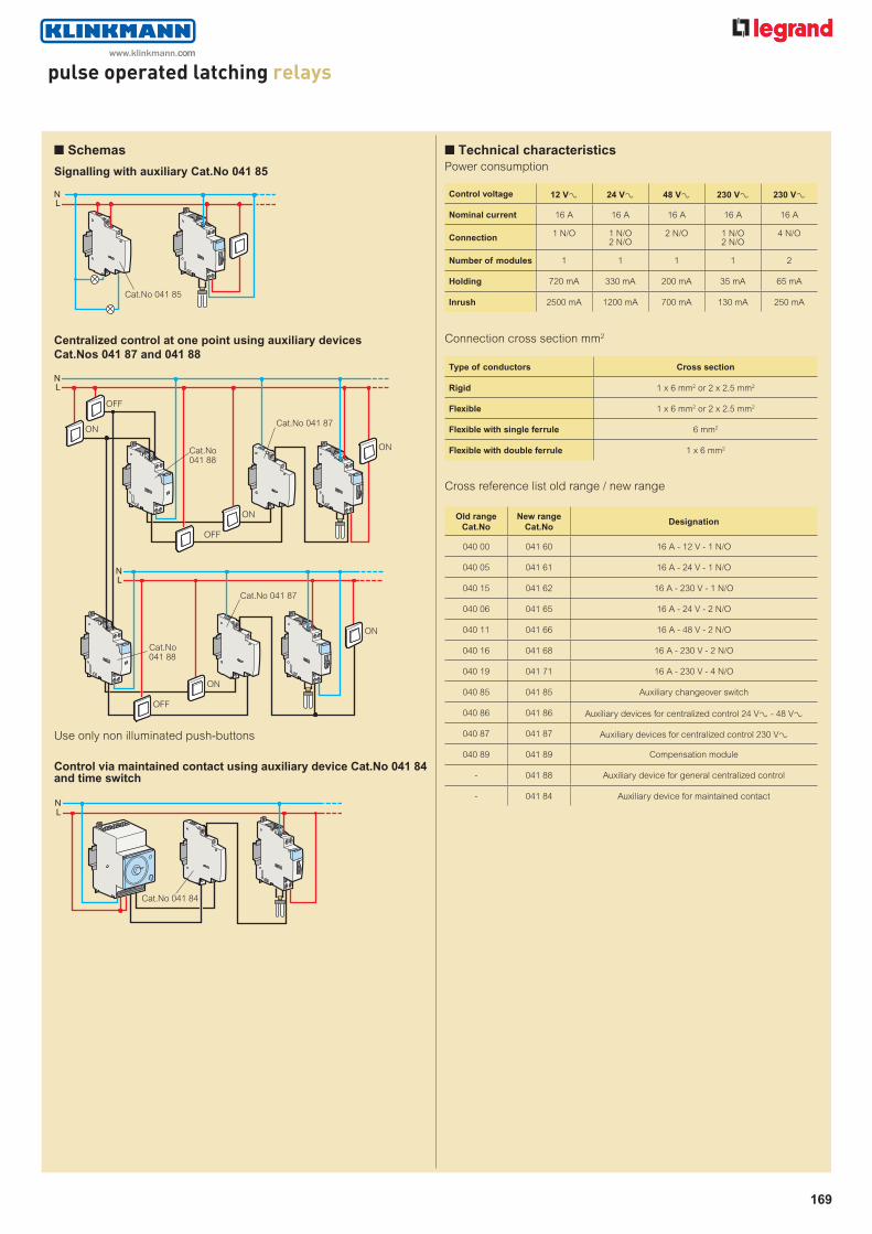
n Technical characteristicsPower consumption
n Schemas
Signalling with auxiliary Cat.No 041 85
Centralized control at one point using auxiliary devices Cat.Nos 041 87 and 041 88
Use only non illuminated push-buttons
Control via maintained contact using auxiliary device Cat.No 041 84 and time switch
LN
Cat.No 041 85
LN
LN
OFF
ON
ON
OFF
ON
OFF
ON
ON
Cat.No041 88
Cat.No 041 87
Cat.No 041 87
Cat.No041 88
LN
Cat.No 041 84
Control voltage 12 VA 24 VA 48 VA 230 VA 230 VA
Nominal current 16 A 16 A 16 A 16 A 16 A
Connection 1 N/O 1 N/O 2 N/O
2 N/O 1 N/O 2 N/O
4 N/O
Number of modules 1 1 1 1 2
Holding 720 mA 330 mA 200 mA 35 mA 65 mA
Inrush 2500 mA 1200 mA 700 mA 130 mA 250 mA
Connection cross section mm2
Cross reference list old range / new range
Old range Cat.No
New range Cat.No
Designation
040 00 041 60 16 A - 12 V - 1 N/O
040 05 041 61 16 A - 24 V - 1 N/O
040 15 041 62 16 A - 230 V - 1 N/O
040 06 041 65 16 A - 24 V - 2 N/O
040 11 041 66 16 A - 48 V - 2 N/O
040 16 041 68 16 A - 230 V - 2 N/O
040 19 041 71 16 A - 230 V - 4 N/O
040 85 041 85 Auxiliary changeover switch
040 86 041 86 Auxiliary devices for centralized control 24 VA - 48 VA
040 87 041 87 Auxiliary devices for centralized control 230 VA
040 89 041 89 Compensation module
- 041 88 Auxiliary device for general centralized control
- 041 84 Auxiliary device for maintained contact
Type of conductors Cross section
Rigid 1 x 6 mm2 or 2 x 2.5 mm2
Flexible 1 x 6 mm2 or 2 x 2.5 mm2
Flexible with single ferrule 6 mm2
Flexible with double ferrule 1 x 6 mm2
www.klinkmann.com

Red catalogue numbers : New products
cex-EP3
170
power contactorsfrom 16 A to 100 A
040 78
Dimensions (p. 183)
Conform to IEC/EN 61095Space for power supply busbar on top (up to 25 A)
Pack Cat.Nos Power contactors with 24 V± coil
2-pole - 250 V± Type Number I max of contact of modules
1 041 14 16 A N/C + N/O 1
1 041 16 25 A 2 N/O 1
4-pole - 400 V±
1 041 17 25 A 4 N/O 2
Pack Cat.Nos Power contactors with 230 V± coil (continued)
2-pole - 250 V± Type Number I max of contact of modules
1 041 29 25 A 2 N/C 1
1 040 95 63 A 2 N/O 2
4-pole - 400 V±
5 041 31 25 A 4 N/O 2
1 041 32 25 A 4 N/C 2
1 041 33 25 A 2 N/O + 2 N/C 2
1 040 98 63 A 4 N/O 3 1 040 99 100 A 4 N/O 6
Power contactors with 230 V± coil and handle
Manual override for test and repair function, carried out via the handle Permanent "ON" or "OFF" without automatic closing of the contactor
2-pole - 250 V± Type Number I max of contact of modules
4 041 47 25 A 2 N/O 1 1 040 68(1) 40 A 2 N/O 2 1 040 75(1) 63 A 2 N/O 2
1 040 76(1) 63 A 2 N/C 2
3-pole - 400 V±
1 040 69(1) 40 A 3 N/O 3 1 040 77(1) 63 A 3 N/C 3
4-pole - 400 V± 2 041 48 25 A 4 N/O 2 1 040 70(1) 40 A 4 N/O 3 1 040 78(1) 63 A 4 N/O 3
1 040 79 63 A 4 N/C 3
Power contactors with 24 V± coil and handle
Manual override for test and repair function, carried out via the handle Permanent "ON" or "OFF" without automatic reset
2-pole - 250 V± Type Number I max of contact of modules 1 041 23 25 A 2 N/O 1 1 040 94(1) 40 A 2 N/O 2 1 040 73(1) 63 A 2 N/O 2
4-pole - 400 V± 1 041 24 25 A 4 N/O 2 1 040 67(1) 40 A 4 N/O 3 1 040 74(1) 63 A 4 N/O 3
Low noise power contactors with 230 V± coil
2-pole - 250 V± Type Number I max of contact of modules 1 041 49 25 A 2 N/O 1
Power contactors with 230 V± coil
2-pole - 250 V± Type Number I max of contact of modules 4 041 26 16 A N/C + N/O 1
10 041 58 25 A 2 N/O 1
24V
24V
24V
24V
24V
230V
230V
230V
230V
230V
230V
230V
230V
230V
230V
230V
230V
230V
230V
041 16 041 23 041 24 041 31 041 47
(1) Handle can be accessed once the blanking plate has been removed
www.klinkmann.com

cex-EP3
171
power contactorsfrom 16 A to 100 A (continued)
power contactorsfrom 16 A to 100 A
• RecommendationsDerating of contactors mounted in modular boxes if the internal temperature is > 40 °C
Install a spacing unit every two contactors (Cat.No 044 40 or 044 41)
• Max. connection cross-section in mm2
Cross reference list old range / new range
Old rangeCat.No
New rangeCat.No Designation
040 33 041 14 16 A - 24 V - N/C + N/O
040 41 041 16(1) / 041 23(2) 25 A - 24 V - 2 N/O
040 43 041 17(1) / 041 24(2) 25 A - 24 V - 4 N/O
040 38 041 26 16 A - 230 V - N/C + N/O
040 49 041 58(1) / 041 47(2) 25 A - 230 V - 2 N/O
040 52 041 49 25 A - 230 V - 2 N/O low noise
040 50 041 29 25 A - 230 V - 2 N/C
040 53 041 31(1) / 041 48(2) 25 A - 230 V - 4 N/O
040 54 041 32 25 A - 230 V - 4 N/C
040 55 041 33 25 A - 230 V - 2 N/C + 2 N/O
040 85
041 85 Auxiliary changeover switch for 1 module 16 and 25 A contactors
041 83 Auxiliary changeover switch for 2 modules 25 A contactors
040 85 Auxiliary changeover switch for 40 A and 63 A contactors
Contactor rating 40 °C 50 °C 60 °C 70 °C Ie = 16 A 16 A 14 A 12 A 10 A Ie = 25 A 25 A 22 A 20 A 18 A Ie = 40 A 40 A 36 A 32 A 29 A Ie = 63 A 63 A 57 A 50 A 45 A
n Technical characteristics• Rated impulsive resistant current (Uimp): 4 kV• Mechanical life in cycles of operations: 106 cycles• Temperature:
- Operation: - 25 °C to + 40 °C- Storage: - 40 °C to +70 °C
Protection of contactors against short-circuits conforming to IEC EN 61095, conditional short-circuit current Iq = 6 kAMCB or gG fuse, rating:
• ≤ 16 A for 16 A rating• ≤ 25 A for 25 A rating• ≤ 40 A for 40 A rating• ≤ 63 A for 63 A rating• ≤ 100 A for 100 A rating
• Control coil consumption
040 85
Pack Cat.Nos Signalling auxiliaries for contactors
Auxiliary changeover switch Used to signal the position status of the contacts on the product to which it is connected
For 1 module contactors 16 A to 25 A Maximum 2 auxiliary devices per contactor
Fitted on left-hand side of contactor Changeover Number I max. Voltage switch of modules 1 041 85 5 A 250 V± N/C + N/O 0.5
For 2 module contactors 25 A Maximum 2 auxiliary devices per contactor
Fitted on left-hand side of contactor Changeover Number I max. Voltage switch of modules 1 041 83 5 A 250 V± N/C + N/O 0.5
For 40 and 63 A contactors Maximum 1 auxiliary device per contactor
Fitted on left-hand side of contactor Changeover Number I max. Voltage switch of modules 1 040 85 5 A 250 V± N/C + N/O 0.5
For 100 A contactors Maximum 1 auxiliary device per contactor
Fitted on right-hand side of contactor Changeover Number I max. Voltage switch of modules 1 035 45 5 A 250 V± N/C + N/O 0.5
041 85 041 83
Power contactors 16 A and 25 A
Control voltage 24 VA 230 VAlow noise 230 VA
Nominal current 16 - 25 A 25 A 25 A 16 - 25 A 16 - 25 A
Type of contact N/O + N/C2 N/C
4 N/O 2 N/O N/O + N/C2 N/O2 N/C
2 N/O + 2 N/C4 N/O4 N/C
Number of modules 1 2 1 1 2
Holding 200 mA 300 mA 6 mA 20 mA 20 mA
Inrush 970 mA 300 mA 55 mA 90 mA 200 mA
Power contactors 40 A, 63 A and 100 A
Control voltage 24 VA 230 VA
Nominal current 40 and63 A
40 and63 A
40 and63 A
40 and63 A 100 A
Type of contact 2 N/O 4 N/O 2 N/O2 N/C
3 N/O4 N/O4 N/C
4 N/O
Number of modules 2 3 2 3 6
Holding 250 mA 270 mA 15 mA 30 mA 60 mA
Inrush 1750 mA 1500 mA 150 mA 200 mA 460 mA
These products are part of protection and distribution systems > See p. 142-143
Type of conductor Ratings ≤ 25 A Ratings 40 and 63 A Ratings 100 A
Rigid 1 x 62 or 2 x 2.52 1 x 252 or 2 x 10² 502
Flexible 1 x 62 or 2 x 2.52 1 x 252 or 2 x 10² 2 x 352
Flexible with single ferrule 1 x 62 1 x 162 -
Flexible with double ferrule 2 x 42 2 x 162 -
(1) Without handle (2) With handle
www.klinkmann.com