Embed Size (px)
Citation preview

IntelliCorp, Inc.
Response to the OMG Analysis and Design Task Force
UML RTF 2.0 Request for Information
Suggested UML Extensions for Agents
Prepared by: James OdellConrad BockIntelliCorp, Inc.
OMG Document: ad/99-12-01
Response Date: 15 December 1999
Contributors: Van ParunakEnvironmental Research Institute of Michigan (ERIM)
Bernhard BauerSeimens
Endorsers: Geoff ArnoldSun Microsystems, Inc.
Jeffrey M. BradshawThe Boeing Company
David LevineIBM
Francis McCabeFujitsu
Kate StoutSun Microsystems, Inc.
David A. TaylorEnterprise Engines Inc.
Craig W. ThompsonObject Services and Consulting, Inc.
Contact: Conrad BockIntelliCorp, Inc1975 El Camino Real WestMountain View, CA 94040(650) [email protected]

IntelliCorp UML 2.0 RFI Response ad/99-12-01
Page 2
Table of Contents
1. INTRODUCTION 3
1.1 Response Introduction 31.2 Abstract 31.3 Objectives 31.4 Scope 31.5 Experiences with UML 1.x 41.6 Need for a major revision RFP 4
2. EXTENDING UML FOR TO MODEL AGENTS 5
3. BACKGROUND 6
3.1. Agent Software Methodologies 63.2. UML 63.3. AUML 7
4. A LAYERED APPROACH TO PROTOCOLS 9
5. LEVEL 1: REPRESENTING THE OVERALL PROTOCOL 12
5.1. Packages 125.2. Templates 13
6. LEVEL 2: REPRESENTING INTERACTIONS AMONG AGENTS 15
6.1. Sequence Diagrams 156.2. Collaboration Diagrams 176.3. Activity diagrams 196.4. Statecharts 20
7. LEVEL 3: REPRESENTING INTERNAL AGENT PROCESSING 21
7.1. Activity Diagrams 217.2. Statecharts 22
8. OTHER AUMLCONSIDERATIONS 23
8.1 Richer role specification 238.2. Package extension 278.3. Deployment diagram extensions 288.4. Other useful agent-based notions 28
9. CONCLUSION 30
REFERENCES 31

IntelliCorp UML 2.0 RFI Response ad/99-12-01
Page 3
1. INTRODUCTION
1.1 Response Introduction
Suggested UML Extensions for Agents is submited to the OMG's Analysis and Design Task Force(ADTF) in response to the Request for Information (RFI) entitled "UML 2.0 RFI." 1
1.2 Abstract
Gaining wide acceptance for the use of agents in industry requires both relating it to the nearestantecedent technology (object-oriented software development) and using artifacts to support thedevelopment environment throughout the full system lifecycle. We address both of these requirements inthis RFI response by describing some of the most common requirements for modeling agents and agent-based systems—using a set of UML idioms and extensions. This RFI response illustrates the approachby presenting a three-layer AUML representation for agent interaction protocols and concludes byincluding other useful agent-based extensions to UML.
1.3 Objectives
The purpose of this RFI response is to suggest possible UML (Unified Modeling Language) extensionsto several UML diagrams that will express agent interaction protocols (AIP) and other useful extensionto modeling agents and agent-based systems. While such extensions might also be used for object-oriented approaches, an immediate need for agents and agent-based systems now exists.
This RFI response seeks to provide information that will help the ADTF determine whether amajor revision to UML 1.x is required and, in the event that it is, assist it to specify the requirements fora major revision RFP. In particular, this response maintains the following:
• Based on our user-base modeling and tool implementation experiences, we have assessed the strengthand weaknesses of the current UML 1.x specification and found that agent interaction protocols couldnot be adequately expressed.
• To accommodate the modeling requirements for interaction protocols, we believe a major revision forUML will be required in the near future.
1.4 Scope
While the OMG Policies and Procedures do not provide detailed guidelines regarding what is inside oroutside the scope of a major revision, Intellicorp proposes the improvements contained in this response.In doing so, we have kept the following in mind:
• Any proposed changes either maintain or improve the rigor and the integrity of the currentspecification.
• All proposed changes consider backward incompatibility issues.• All proposed changes consider the pragmatics of usage and implementation within a reasonable time
frame.
1 The FIPA response (ad/99-12-03) has some overlap with this submission; however—together—theFIPA and Intellicorp agent-based RFI responses provide a fuller response than either separately.

IntelliCorp UML 2.0 RFI Response ad/99-12-01
Page 4
1.5 Experiences with UML 1.x
FIPA has assessed the strengths and weaknesses of the UML 1.x specification based on user modelingand tool vendor implementation experiences. In particular, this response addresses the following subsetof solicited experiences:
4.1.4 Are there any parts of the specification that need further clarification or expansion?This response suggests that some further expansion is required to express interaction protocolsmore clearly.
4.1.6 What are the most difficult issues facing UML modelers and implementers? How should theseissues be resolved?This response suggests that adequately representing agents and agent-based notions (such asinteraction protocols, roles, packages, platform deployment, and other useful agent-relatedmodeling techniques) are both an important as well as difficult issue facing UML modelers andimplementers. Intellicorp suggests that the extensions to the Unified Modeling Languageproposed in this document will alleviate many of the problems encountered by agent modelers.
4.1.7 What UML profiles are you using or do you plan to use?Our experience indicates that most—if not all—extensions recommended in this RFI responseare also required or desired by object-oriented analysis and design. As such, an additionalprofile might not be not required. However, if the UML Revision Task Force determines that oneor more of the recommendations in this paper are solely agent-based extension, an Agent UMLProfile might be appropriate for UML 2.0.
4.1.8 Are you using UML for any applications outside its original scope?Agent-based applications were not in the original scope of UML. However, the agent-basedapproach is now becoming a prominently employed technology. Again, many object-orientedapplications have also found—independently—that many of the properties of agent systems arealso useful for object systems.
1.6 Need for a major revision RFP
Respondents are asked to provide their opinion regarding the need for, and the timing of, one or moremajor revision RFPs. They are asked to answer the following questions:
4.2.1 Why or why not is a major revision of UML specification required within the next 2 years?Agent-based technology is just now becoming widely used. Without a standard modelinglanguage to support these in a relatively short time frame, users will most probably respond bydefining their own interaction protocol modeling languages— resulting in a tour of modeling-language Babel similar to that which existed prior to UML. In our opinion, a two-year time frameis a maximum.
4.2.2 If you think a major revision is required, should more than one RFP be issued? If so, how shouldthe requirements be distributed among multiple RFPs?As mentioned above, our experience indicates that the extensions recommended in this RFIresponse are also required or desired by object-oriented analysis and design. As such, a singleRFP might only be required. However, if the UML Revision Task Force determines that one ormore of the recommendations in this paper are solely agent-based extension, a separate agent-based RFP might be appropriate for UML 2.0.
IntelliCorp UML 2.0 RFI Response ad/99-12-01
Page 5
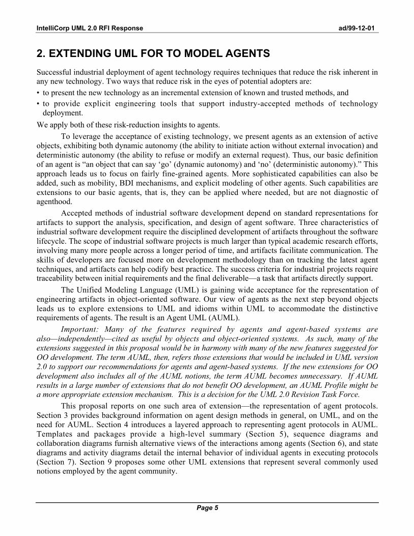
2. EXTENDING UML FOR TO MODEL AGENTS
Successful industrial deployment of agent technology requires techniques that reduce the risk inherent inany new technology. Two ways that reduce risk in the eyes of potential adopters are:• to present the new technology as an incremental extension of known and trusted methods, and• to provide explicit engineering tools that support industry-accepted methods of technology
deployment.
We apply both of these risk-reduction insights to agents.
To leverage the acceptance of existing technology, we present agents as an extension of activeobjects, exhibiting both dynamic autonomy (the ability to initiate action without external invocation) anddeterministic autonomy (the ability to refuse or modify an external request). Thus, our basic definitionof an agent is “an object that can say ‘go’ (dynamic autonomy) and ‘no’ (deterministic autonomy).” Thisapproach leads us to focus on fairly fine-grained agents. More sophisticated capabilities can also beadded, such as mobility, BDI mechanisms, and explicit modeling of other agents. Such capabilities areextensions to our basic agents, that is, they can be applied where needed, but are not diagnostic ofagenthood.
Accepted methods of industrial software development depend on standard representations forartifacts to support the analysis, specification, and design of agent software. Three characteristics ofindustrial software development require the disciplined development of artifacts throughout the softwarelifecycle. The scope of industrial software projects is much larger than typical academic research efforts,involving many more people across a longer period of time, and artifacts facilitate communication. Theskills of developers are focused more on development methodology than on tracking the latest agenttechniques, and artifacts can help codify best practice. The success criteria for industrial projects requiretraceability between initial requirements and the final deliverable—a task that artifacts directly support.
The Unified Modeling Language (UML) is gaining wide acceptance for the representation ofengineering artifacts in object-oriented software. Our view of agents as the next step beyond objectsleads us to explore extensions to UML and idioms within UML to accommodate the distinctiverequirements of agents. The result is an Agent UML (AUML).
Important: Many of the features required by agents and agent-based systems arealso—independently—cited as useful by objects and object-oriented systems. As such, many of theextensions suggested in this proposal would be in harmony with many of the new features suggested forOO development. The term AUML, then, refers those extensions that would be included in UML version2.0 to support our recommendations for agents and agent-based systems. If the new extensions for OOdevelopment also includes all of the AUML notions, the term AUML becomes unnecessary. If AUMLresults in a large number of extensions that do not benefit OO development, an AUML Profile might bea more appropriate extension mechanism. This is a decision for the UML 2.0 Revision Task Force.
This proposal reports on one such area of extension—the representation of agent protocols.Section 3 provides background information on agent design methods in general, on UML, and on theneed for AUML. Section 4 introduces a layered approach to representing agent protocols in AUML.Templates and packages provide a high-level summary (Section 5), sequence diagrams andcollaboration diagrams furnish alternative views of the interactions among agents (Section 6), and statediagrams and activity diagrams detail the internal behavior of individual agents in executing protocols(Section 7). Section 9 proposes some other UML extensions that represent several commonly usednotions employed by the agent community.

IntelliCorp UML 2.0 RFI Response ad/99-12-01
Page 6
3. BACKGROUND
Agent UML (AUML) synthesizes a growing concern for agent-based software methodologies with theincreasing acceptance of UML for object-oriented software development.
3.1. Agent Software Methodologies
The agent R&D community is increasingly interested in design methods and representational tools tosupport the associated artifacts (see [12] for a helpful survey). Multi-Agent System Engineering was thefocus of a session at ATAL’97 [5, 10, 13, 17, 19, 23, 25, 26] and the entire MAAMAW’99 [9].
A number of groups have reported on methodologies for agent design, touching onrepresentational mechanisms as they support the methodology. Our own report [23] emphasizesmethodology, as does the work by Kinny and colleagues [15, 16] on modeling techniques for BDIagents. The close parallel that we observe between design mechanisms for agents and for objects isshared by a number of authors, for example [5, 6].
The GAIA methodology [28] includes specific recommendations for notation that supports thehigh-level summary of a protocol as an atomic unit, a notation that is reflected in our recommendations.The extensive program underway at the Free University of Amsterdam on compositional methodologiesfor requirements [11], design [4], and verification [14] uses graphical representations with strong linksto UML’s collaboration diagrams, as well as linear (formulaic) notations better suited to alignment withUML’s metamodel than with the graphical mechanisms that are our focus. Our discussion of thecompositionality of protocols is anticipated in the work of Burmeister et al. [7], though our notationdiffers widely from hers. Dooley graphs facilitate the identification of the “character” that results froman agent playing a specific role (as distinct from the same agent playing a different role) [21, 27]. Wecapture this distinction by leveraging UML’s existing name/role:class syntax in conjunction withcollaboration diagrams.
This wide-ranging activity is a healthy sign that agent-based systems are having an increasingimpact, since the demand for methodologies and artifacts reflects the growing commercial importance ofour technology. Our objective is not to compete with any of these efforts, but rather to extend and applya widely accepted modeling and representational formalism (UML)—one that harnesses insights andmakes them useful for communicating across a wide range of research groups and developmentmethodologies.
3.2. UML
During the seventies, structured programming was the dominant approach to software development.Along with it, software engineering technologies were developed in order to ease and formalize thesystem development lifecycle: from planning, through analysis and design, and finally to systemconstruction, transition, and maintenance. In the eighties, object-oriented (OO) languages experienced arise in popularity, bringing with it new concepts such as data encapsulation, inheritance, messaging, andpolymorphism. By the end of the eighties and beginning of the nineties, a jungle of modeling approachesgrew to support the OO marketplace. To make sense of and unify these various approaches, an Analysisand Design Task Force was established on 29 June 1995 within the OMG. By November 1997, a de jurestandard was adopted by the OMG members called the Unified Modeling Language (UML).
IntelliCorp UML 2.0 RFI Response ad/99-12-01
Page 7
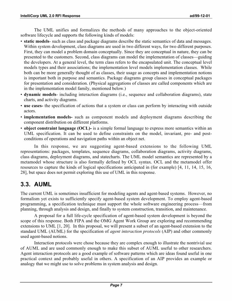
The UML unifies and formalizes the methods of many approaches to the object-orientedsoftware lifecycle and supports the following kinds of models:• static models- such as class and package diagrams describe the static semantics of data and messages.
Within system development, class diagrams are used in two different ways, for two different purposes.First, they can model a problem domain conceptually. Since they are conceptual in nature, they can bepresented to the customers. Second, class diagrams can model the implementation of classes—guidingthe developers. At a general level, the term class refers to the encapsulated unit. The conceptual levelmodels types and their associations; the implementation level models implementation classes. Whileboth can be more generally thought of as classes, their usage as concepts and implementation notionsis important both in purpose and semantics. Package diagrams group classes in conceptual packagesfor presentation and consideration. (Physical aggregations of classes are called components which arein the implementation model family, mentioned below.)
• dynamic models- including interaction diagrams (i.e., sequence and collaboration diagrams), statecharts, and activity diagrams.
• use cases- the specification of actions that a system or class can perform by interacting with outsideactors.
• implementation models- such as component models and deployment diagrams describing thecomponent distribution on different platforms.
• object constraint language (OCL)- is a simple formal language to express more semantics within anUML specification. It can be used to define constraints on the model, invariant, pre- and post-conditions of operations and navigation paths within an object net.
In this response, we are suggesting agent-based extensions to the following UMLrepresentations: packages, templates, sequence diagrams, collaboration diagrams, activity diagrams,class diagrams, deployment diagrams, and statecharts. The UML model semantics are represented by ametamodel whose structure is also formally defined by OCL syntax. OCL and the metamodel offerresources to capture the kinds of logical specifications anticipated in (for example) [4, 11, 14, 15, 16,28], but space does not permit exploring this use of UML in this response.
3.3. AUML
The current UML is sometimes insufficient for modeling agents and agent-based systems. However, noformalism yet exists to sufficiently specify agent-based system development. To employ agent-basedprogramming, a specification technique must support the whole software engineering process—fromplanning, through analysis and design, and finally to system construction, transition, and maintenance.
A proposal for a full life-cycle specification of agent-based system development is beyond thescope of this response. Both FIPA and the OMG Agent Work Group are exploring and recommendingextensions to UML [1, 20]. In this proposal, we will present a subset of an agent-based extension to thestandard UML (AUML) for the specification of agent interaction protocols (AIP) and other commonlyused agent-based notions.
Interaction protocols were chose because they are complex enough to illustrate the nontrivial useof AUML and are used commonly enough to make this subset of AUML useful to other researchers.Agent interaction protocols are a good example of software patterns which are ideas found useful in onepractical context and probably useful in others. A specification of an AIP provides an example oranalogy that we might use to solve problems in system analysis and design.

IntelliCorp UML 2.0 RFI Response ad/99-12-01
Page 8
We want to suggest a specification technique for AIPs with both formal and intuitive semanticsand a user-friendly graphical notation. The semantics allows a precise definition that is also usable in thesoftware-engineering process. The graphical notation provides a common language for communicatingAIPs—particularly with people not familiar with the agent-based approach.Before proceeding, we need to establish a working definition:
An agent interaction protocol (AIP) describes a communication pattern as anallowed sequence of messages between agents and the constraints on thecontent of those messages.

IntelliCorp UML 2.0 RFI Response ad/99-12-01
Page 9
4. A LAYERED APPROACH TO PROTOCOLS
Figure 1 depicts a protocol expressed as a UML sequence diagram for the contract net protocol. Wheninvoked, an Initiator agent sends a call for proposal to an agent that is willing to participate in providinga proposal. The Participant agent can then choose to respond to the Initiator before a given deadline by:refusing to provide a proposal, submitting a proposal, or indicating that it did not understand. (Thediamond symbol indicates a decision that can result in zero or more communications beingsent—depending on the conditions it contains; the “x” in the decision diamond indicates an exclusive ordecision.) If a proposal is offered, the initiator has a choice of either accepting or rejecting the proposal.When the participant receives a proposal acceptance, it will inform the initiator about the proposal’sexecution. Additionally, the Initiator can cancel the execution of the proposal at any time. (Note: thestick arrows indicate unnested, asynchronous communications (messages). The interpretation of theterm "unnested" in UML 1.3—as communicated via email from Gunnar Overgaard—is not yet welldefined in a UML document. This notations can be changed, once a firm standard exists for unnested,asynchronous communications.)
contract initiation
call-for-proposal
FIPA Contract Net Protocol
Initiator Participant
refuse
not-understood
propose
accept-proposal
reject-proposal
inform
cancel
deadline
x
x
Initiator, ParticipantDeadline
call-for-proposal, refuse*, not-understood*, propose,
reject-proposal*, accept-proposal*, cancel*, inform*
Figure 1. A generic AIP expressed as a template package.

IntelliCorp UML 2.0 RFI Response ad/99-12-01
Page 10
This figure also expresses two more concepts represented at the top of the sequence chart. First,the protocol as a whole is treated as an entity in its own right. The tabbed folder notation at the upper leftindicates that the protocol is a package, a conceptual aggregation of interaction sequences. Second, thepackaged protocol can be treated as a pattern that can be customized for analogous problem domains.The dashed box at the upper right-hand corner expresses this pattern as a template specification thatidentifies unbound entities within the package which need to be bound when the package template isbeing instantiated.
The original sequence diagram in Fig. 1 provides a basic specification for a contract net protocol.More processing detail is often required. For example, an Initiator agent requests a call for proposal(CFP) from a Participant agent. However, the diagram stipulates neither the procedure used by theInitiator to produce the CFP request, nor the procedure employed by the participant to respond to theCFP. Yet, such details are important for developing detailed agent-based system specifications.
Figure 2 illustrates how leveling can express more detail for any interaction process. Forexample, the process that generated the communication act CA-1 could be complex enough to specify itsprocessing in more detail using an activity diagram. The agent receiving CA-1 has a process thatprepares a response. In this example, the process being specified is depicted using a sequence diagram,though any modeling language could be chosen to further specify an agent’s underlying process. InUML, the choice is an interaction diagram, an activity diagram, or a statechart.
Role-1 Role-2
••• •••
CA-1
CA-2
CA-3
CA-4
Role-3x
y
g z
Role-2
Figure 2. Interaction protocols can be specified in more detail (i.e., leveled or nested)using a combination of diagrams.
IntelliCorp UML 2.0 RFI Response ad/99-12-01
Page 11
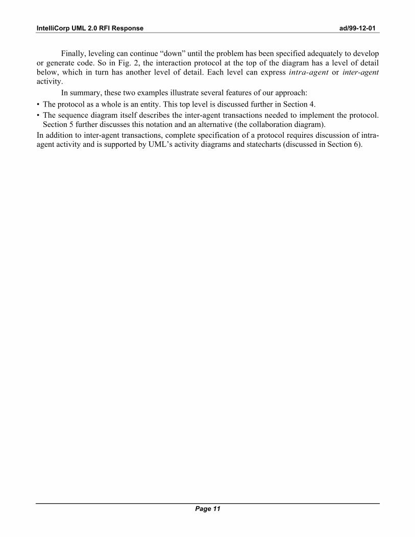
Finally, leveling can continue “down” until the problem has been specified adequately to developor generate code. So in Fig. 2, the interaction protocol at the top of the diagram has a level of detailbelow, which in turn has another level of detail. Each level can express intra-agent or inter-agentactivity.
In summary, these two examples illustrate several features of our approach:
• The protocol as a whole is an entity. This top level is discussed further in Section 4.• The sequence diagram itself describes the inter-agent transactions needed to implement the protocol.
Section 5 further discusses this notation and an alternative (the collaboration diagram).In addition to inter-agent transactions, complete specification of a protocol requires discussion of intra-agent activity and is supported by UML’s activity diagrams and statecharts (discussed in Section 6).

IntelliCorp UML 2.0 RFI Response ad/99-12-01
Page 12
5. LEVEL 1: REPRESENTING THE OVERALL PROTOCOL
Patterns are ideas that have been found useful in one practical context and can probably be useful inothers. As such, they give us examples or analogies that we might use as solutions to problems in systemanalysis and design. Agent interaction protocols, then, provide us with reusable solutions that can beapplied to various kinds of message sequencing we encounter between agents. There are two UMLtechniques that best express protocol solutions for reuse: packages and templates.
5.1. Packages
Since interaction protocols are patterns, they can be treated as reusable aggregates of processing. UMLdescribes two ways of expressing aggregation for OO structure and behavior: components and packages.Components are physical aggregations that compose classes for implementation purposes. Packagesaggregate modeling elements into conceptual wholes. Here, classes can be conceptually grouped for anyarbitrary purpose, such as a subsystem grouping of classes. Since AIPs can be viewed in conceptualterms, the package notation of a tabbed folder was employed in Fig. 1.2
call-for-proposal
Purchasing
Supplying
Broker Retailer Wholesaler
request
inform
propose
•••
Figure 3. Using packages to express nested protocols. 2 In UML 1.3, packages only group class diagrams as a unit. However, we recommend that behavior-
related diagrams should also be grouped using the same mechanism—instead of defining yet-anothersymbol. And more generally, packages should also be used to group any arbitrary model grouping.

IntelliCorp UML 2.0 RFI Response ad/99-12-01
Page 13
Because protocols can be codified as recognizable patterns of agent interaction, they becomereusable modules of processing that can be treated as first-class notions. For example, Fig. 3 depicts twopackages. The Purchasing package expresses a simple protocol between a Broker and a Retailer.Here, the Broker sends a call for proposal to a Retailer and the Retailer responds with a proposal. Forcertain products, the Retailer might also place a request with a Wholesaler regarding availability andcost. Based on the return information, the Retailer can provide a more accurate proposal. All of thiscould have been put into a single Purchasing Protocol package. However, many businesses ordepartments may not need the additional protocol involving the Wholesaler. Therefore, two packagescan be defined: one for Purchasing and one for Supplying. When a particular scenario requires thewholesaler protocol, it can be nested as a separate and distinct package. However, when a purchasingscenario does not require it, the package is more parsimonious.
Burmeister et al. suggest a similar construct when they describe their complex cooperationprotocols [7]. Their three primitive protocols—offering, requesting, and proposing—“are generalenough to be used in a large number of interaction situations.” Their approach “allows for theconstruction of (more complex) application or task protocols.” In addition to their three primitiveprotocols, we advocate a pragmatic approach where the analyst may extend Burmeister’s general set toinclude any protocols that might be reused for a nested specification—using AUML.
5.2. Templates
Figure 1 illustrates a common kind of behavior that can serve as a solution in analogous problemdomains. In Fig. 3, the supplying behavior is reused exactly as defined by the Supplying package.However, to be truly a pattern—instead of just a reusable component—package customization must besupported. For example, Fig. 4 applies the FIPA Contract Net Protocol to a particular scenario involvingbuyers and sellers. Notice that the Initiator and Participant agents have become Buyer and Selleragents, and the call-for-proposal has become the seller-rfp. Also in this scenario are two forms ofrefusal by the seller: Refuse-1 and Refuse-2. Lastly, an actual deadline has been supplied for aresponse by the seller.
In UML argot, the AIP package serves as a template. A template is a parameterized modelelement whose parameters are bound at model time (i.e., when the new customized model is produced).In Fig. 1, the dotted box in the upper right indicates that the package is a template. The unboundparameters in the box are divided by horizontal lines into three categories: role parameters, constraints,and communication acts. Figure 5 illustrates how the new package in Fig. 4 is produced using thetemplate definition in Fig. 1.3 Wooldridge et al. suggest a similar form of definition with their protocoldefinitions [28]. In their packaged templates “a pattern of interaction . . . has been formally defined andabstracted away from any particular sequence of execution steps. Viewing interactions in this waymeans that attention is focussed on the essential nature and purpose of interaction rather than the preciseordering of particular message exchanges.” Instead of the notation illustrated by Wooldridge et al., ourgraphical approach more closely resembles UML, while expressing the same semantics.
3 This template format is not currently UML compliant but is recommended for future UML extensions.

IntelliCorp UML 2.0 RFI Response ad/99-12-01
Page 14
seller-rfp
Buyer Seller
refuse-1
not-understood
propose
accept-proposal
reject-proposal
inform
cancel
deadline:8/8/99 at
12:00 hoursx
x
xrefuse-2
Figure 4. Applying the template in Fig. 1 to a particular scenario involving buyers and sellers.
Buyer, Seller
FIPA Contract Net Protocol
8/8/99 at 12:00
seller-rfp, refuse-1, refuse-2, not-understood, propose,reject-proposal, accept-proposal, cancel, inform
Figure 5. Producing a new package using the Fig. 1 template; Fig. 4 is the resulting model.
IntelliCorp UML 2.0 RFI Response ad/99-12-01
Page 15
6. LEVEL 2: REPRESENTING INTERACTIONS AMONG AGENTS
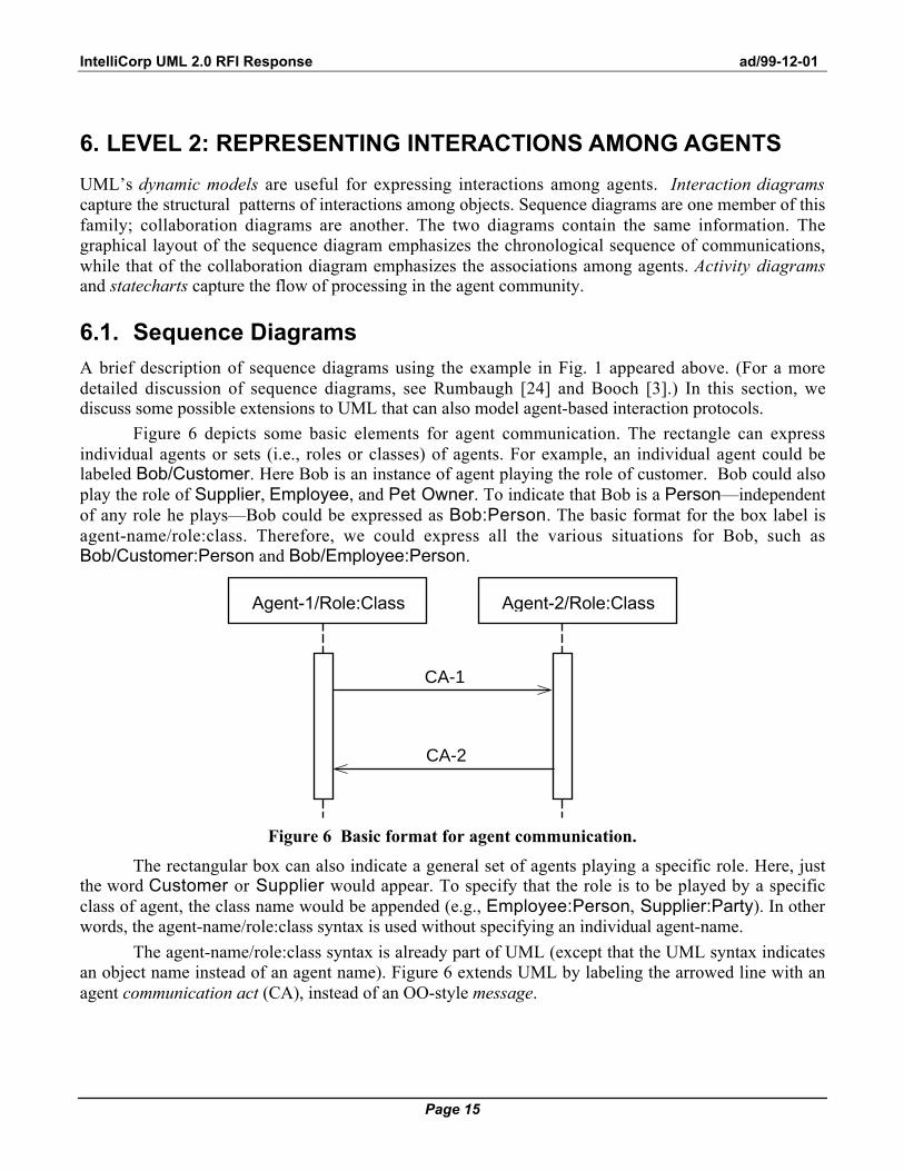
UML’s dynamic models are useful for expressing interactions among agents. Interaction diagramscapture the structural patterns of interactions among objects. Sequence diagrams are one member of thisfamily; collaboration diagrams are another. The two diagrams contain the same information. Thegraphical layout of the sequence diagram emphasizes the chronological sequence of communications,while that of the collaboration diagram emphasizes the associations among agents. Activity diagramsand statecharts capture the flow of processing in the agent community.
6.1. Sequence Diagrams
A brief description of sequence diagrams using the example in Fig. 1 appeared above. (For a moredetailed discussion of sequence diagrams, see Rumbaugh [24] and Booch [3].) In this section, wediscuss some possible extensions to UML that can also model agent-based interaction protocols.
Figure 6 depicts some basic elements for agent communication. The rectangle can expressindividual agents or sets (i.e., roles or classes) of agents. For example, an individual agent could belabeled Bob/Customer. Here Bob is an instance of agent playing the role of customer. Bob could alsoplay the role of Supplier, Employee, and Pet Owner. To indicate that Bob is a Person—independentof any role he plays—Bob could be expressed as Bob:Person. The basic format for the box label isagent-name/role:class. Therefore, we could express all the various situations for Bob, such asBob/Customer:Person and Bob/Employee:Person.
Agent-1/Role:Class
CA-1
Agent-2/Role:Class
CA-2
Figure 6 Basic format for agent communication.
The rectangular box can also indicate a general set of agents playing a specific role. Here, justthe word Customer or Supplier would appear. To specify that the role is to be played by a specificclass of agent, the class name would be appended (e.g., Employee:Person, Supplier:Party). In otherwords, the agent-name/role:class syntax is used without specifying an individual agent-name.
The agent-name/role:class syntax is already part of UML (except that the UML syntax indicatesan object name instead of an agent name). Figure 6 extends UML by labeling the arrowed line with anagent communication act (CA), instead of an OO-style message.

IntelliCorp UML 2.0 RFI Response ad/99-12-01
Page 16
•••
CA-n
CA-2
CA-1
•••
CA-n
CA-2
CA-1
•••
CA-n
CA-2
CA-1
x
(a) (b) (c)
Figure 7. Some recommended extensions that support concurrent threads of interaction.
CA-1
Agent
or[role-1]
[role-1]
Agent Agent Agent
CA-2
CA-3
CA-1
CA-2
CA-3
(a) (b)
Agent Agent Agent Agent
or
CA-1
CA-2
CA-3
CA-1
CA-2
CA-3
(c) (d)
Agent Agent Agent Agent
or
CA-1
CA-2
CA-3
CA-1
CA-2
CA-3
x x
x
(e) (f)
Figure 8. Multiple techniques to express concurrent communication with an agent playing multiple roles or responding to different CAs.

IntelliCorp UML 2.0 RFI Response ad/99-12-01
Page 17
Another recommended extension to UML supports concurrent threads of interaction. Whileconcurrent threads are not forbidden in OO, they are not commonly employed.4 Figure 7 depicts threeways of expressing multiple threads. Figure 7(a) indicates that all threads CA-1 to CA-n are sentconcurrently. Figure 7(b) includes a decision box indicating that a decision box will decide which CAs(zero or more) will be sent. If more than one CA is sent, the communication is concurrent. In short, itindicates an inclusive or. Fig. 7(c) indicates an exclusive or, so that exactly one CA will be sent. Figure7(a) indicates an and communication.
Figure 8 illustrates one way of using the concurrent threads of interaction depicted in Fig. 7.Figures 8(a) and (b) portray two ways of expressing concurrent threads sent from agent-1 to agent-2.The multiple vertical, or activation, bars indicate that the receiving agent is processing the variouscommunication threads concurrently. Figure 8(a) displays parallel activation bars and Fig. 8(b)activation bars that appear on top of each other. A few things should be noted about these twovariations:
• The semantic meaning is equivalent; the choice is based on ease and clarity of visual appearance.• Each activation bar can indicate either that the agent is using a different role or that it is merely
employing a different processing thread to support the communication act. If the agent is using adifferent role, the activation bar can be annotated appropriately. For example in Figs. 8(a) and (b), CA-n is handled by the agent under its role-1 processing.
• These figures indicate that a single agent is concurrently processing the multiple CAs. However, theconcurrent CAs could each have been sent to a different agent, e.g., CA-1 to agent-2, CA-2 to agent-3, and so on. Such protocol behavior is already supported by UML; the notation in Fig. 7, on the otherhand, is a recommended extension to UML.
(For more detailed treatment of these extensions to the UML sequence diagram for protocols, seethe FIPA response, ad/99-12-03)
6.2. Collaboration Diagrams
Figure 9 is an example of a collaboration diagram and depicts a pattern of interaction among agents. Oneof the primary distinctions of the collaboration diagram is that the agents (the rectangles) can be placedanywhere on the diagram; whereas in a sequence diagram, the agents are placed in a horizontal row atthe diagram’s top. The sequence of interactions are numbered on the collaboration diagram; whereas theinteraction diagram is basically read from the top down. If the two interaction diagrams are so similar,why have both? The answer lies primarily in how clear and understandable the presentation is.Depending on the person and interaction protocol being described, one diagram type might provide aclearer, more understandable representation over another. Semantically, they are equivalent; graphicallythey are similar. For example, Fig. 10 expresses the same underlying meaning as Fig. 8 using thesequence diagram. Experience has demonstrated that agent-based modelers can find both types ofdiagrams useful.
4 As OO implementations become more advanced, such an extension would be considered useful in any
case.

IntelliCorp UML 2.0 RFI Response ad/99-12-01
Page 18
12: assert + request14:
6:
2: question
3:
4:
10: refuse
5: propose7: commit
8: commit11: ship
9: assert
13: ship
1.1: request
<<role change>>
1.2: request
1.3: request
<<role change>>
<<role change>>
C /Contractor2
C /Contractor1
B /Contractor
A Customer
B /Competitor
Analyzer
C /Competitor
D /Contractor
D /Debtor
A /Negotiator
Figure 9. An example of a collaboration diagram depicting aninteraction among agents playing multiple roles.
assert + request
pay
request
questioninform
refuse
refuse
propose
commit
commit
assert
ship
ship
<<role change>>
<<role change>>
<<role change>>
C /Contractor1
C /Contractor2
C /Competitor
D /Contractor
D /Debtor
A /Negotiator
B /Contractor
A /Customer
B /Competitor
Analyzer
request
Figure 10. A sequence diagram version of Fig. 9.
Dooley Graphs [21] are isomorphic to collaboration diagrams. The critical distinction is that asingle agent can appear as multiple nodes in a Dooley Graph. The ICMAS paper calls these nodescharacters. The intuition in the terminology is that a character is a specific agent playing a specific role.The role is an abstraction over several characters with similar patterns of interaction. Inversely, each
IntelliCorp UML 2.0 RFI Response ad/99-12-01
Page 19
node is an agent in a specific role, where "role" is here defined fairly narrowly (not just purchaser, forexample, but purchaser under a renegotiated contract in contrast with the same purchaser's role in theoriginal contract).
Given our notation for an agent playing a role and having a precise enough definition of roles,we could construct a collaboration diagram that has the same semantic content as a Dooley Graph.
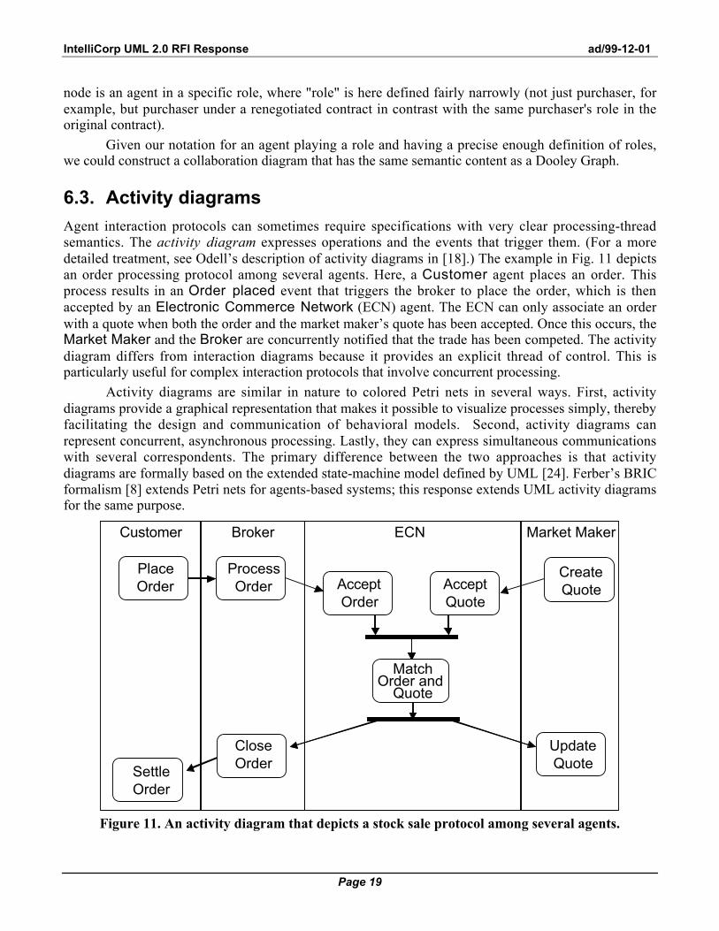
6.3. Activity diagrams
Agent interaction protocols can sometimes require specifications with very clear processing-threadsemantics. The activity diagram expresses operations and the events that trigger them. (For a moredetailed treatment, see Odell’s description of activity diagrams in [18].) The example in Fig. 11 depictsan order processing protocol among several agents. Here, a Customer agent places an order. Thisprocess results in an Order placed event that triggers the broker to place the order, which is thenaccepted by an Electronic Commerce Network (ECN) agent. The ECN can only associate an orderwith a quote when both the order and the market maker’s quote has been accepted. Once this occurs, theMarket Maker and the Broker are concurrently notified that the trade has been competed. The activitydiagram differs from interaction diagrams because it provides an explicit thread of control. This isparticularly useful for complex interaction protocols that involve concurrent processing.
Activity diagrams are similar in nature to colored Petri nets in several ways. First, activitydiagrams provide a graphical representation that makes it possible to visualize processes simply, therebyfacilitating the design and communication of behavioral models. Second, activity diagrams canrepresent concurrent, asynchronous processing. Lastly, they can express simultaneous communicationswith several correspondents. The primary difference between the two approaches is that activitydiagrams are formally based on the extended state-machine model defined by UML [24]. Ferber’s BRICformalism [8] extends Petri nets for agents-based systems; this response extends UML activity diagramsfor the same purpose.
Customer Broker Market MakerECN
PlaceOrder
ProcessOrder
CreateQuoteAccept
QuoteAcceptOrder
MatchOrder and
Quote
CloseOrder
SettleOrder
UpdateQuote
Figure 11. An activity diagram that depicts a stock sale protocol among several agents.

IntelliCorp UML 2.0 RFI Response ad/99-12-01
Page 20
6.4. Statecharts
Another process-related UML diagram is the statechart. A statechart is a graph that represents a statemachine. States are represented as round-cornered rectangles, while transitions are generally rendered bydirected arcs that interconnect the states. Figure 12 depicts an example of a statechart that governs anOrder protocol. Here, if a given order is in a Requested state, a supplier agent may commit to therequested negotiation—resulting in a transition to a Committed negotiation state. Furthermore, thisdiagram indicates that an agent’s commit action may occur only if the order is in a Requested state.The Requested state has two other possible actions besides the commit: the supplier may refuse andthe consumer may back out. Notice that the supplier may refuse with the order in either the Proposedor the Requested states.
A: request
B: B: ship
A: assert
B: commit
A: assert
B. renege
B: refuseA: assert
B: refuse
Open
Proposed Requested Committed
A: pay
A: assert
Closed
Paid
Rejected
Aborted
Reneged
Shipped
Figure 12. A statechart indicating the valid states and transitions governing an Order protocol.
The statechart is not commonly used to express interaction protocol because it is a state-centricview, rather than an agent- or process-centered view. The agent-centric view portrayed by interactiondiagrams emphasizes the agent first and the interaction second. The process-centric view emphasizes theprocess flow (by agent) first and the resulting state change (i.e., event) second. The state-centric viewemphasizes the permissible states more prominently than the transition agent processing. The primarystrength of the statechart in agent interaction protocols is as a constraint mechanism for the protocol.The statechart and its states are typically not implemented directly as agents. However, an Order agentcould embody the state-transition constraints, thereby ensuring that the overall interaction protocolcontraints are met. Alternatively, the constraints could be embodied in the supplier and customer rolesplayed by the agents involved in the order process.

IntelliCorp UML 2.0 RFI Response ad/99-12-01
Page 21
7. LEVEL 3: REPRESENTING INTERNAL AGENT PROCESSING
At the lowest level, specification of an agent protocol requires spelling out the detailed processing thattakes place within an agent in order to implement the protocol. In a holarchic model, higher-level agents(holons) consist of aggregations of lower-level agents. The internal behavior of a holon can thus bedescribed using any of the Level 2 representations recursively. In addition, state charts and activitydiagrams can also specify the internal processing of agents that are not aggregates, as illustrated in thissection.
7.1. Activity Diagrams
Figure 13 depicts the detailed processing that takes place within an Order Processor agent. Here, asequence diagram indicated that the agent's process is triggered by a Place Order CA and ends with theorder completed. The internal processing by the Order Processor is expressed as an activity diagram,where the Order Processor accepts, assembles, ships, and closes the order. The dotted operation boxesrepresent interfaces to processes carried out by external agents—as also illustrated in the sequencediagram. For example, the diagram indicates that when the order has been assembled, both AssembleOrder and Prepare/send Invoice actions are triggered concurrently. Furthermore, when both thepayment has been accepted and the order has been shipped, the Close Order process can only then beinvoked.
completed
(Payment)(Invoice)
OrderAccepted
Orderplaced
OrderClose
Orderaccepted
Orderassembled
OrderShip
Ordershipped
Order
Paymentaccepted
OrderAssembled
Customer
Place order
Completed
Order Processor Invoice Sender Payment Receiver
Invoice request
Received payment
Invoice
Prepare/send
PaymentProcess
Figure 13. An activity diagram that specifies order processing behavior for an Order agent.

IntelliCorp UML 2.0 RFI Response ad/99-12-01
Page 22
7.2. Statecharts
The internal processing of a single agent can also be expressed as statecharts. Figure 14 depicts theinternal states and transitions for Order Processor, Invoice Sender, and Payment Receiver agents.As with the activity diagram above, these agents interface with each other—as indicated by the dashedlines. This intra-agent use of UML statecharts supports Singh’s notion of agent skeletons [27].
Null
Accepted
Assembled
Order placed Accept Order
Order cancelled Close Order
Shipped
[Order shipped & Order]Close Order
Order AcceptedAssemble Order
Order assembledShip Order
toInvoice Issuer
statechart
Closed
fromPayment Receiver
statechart
Order cancelled Close Order
OrderProcessor
(a)
Null
Transmitted
Paid
Order assembled Prepare/send Invoice
Customer pays Mark invoice paid
30 days after due dateMark invoice overdue
fromOrder
Processorstatechart
Overdue
Null
Received
Accepted
Payment madeReceive Payment
Unacceptable Payment received
Rejected
Acceptable Payment received
toOrder
Processorstatechart
PaymentReceiver
Reject Payment
Accept Payment
Invoice Issuer
Customer pays Mark invoice paid
(b) (c)
Figure 14. Statechart that specifies order processing behavior for the three agents.

IntelliCorp UML 2.0 RFI Response ad/99-12-01
Page 23
8. OTHER AUMLCONSIDERATIONS
The previous sections were constrained to examine AUML extensions for agent interaction protocols.This section presents some other agent and agent-based notions that are also recommended for inclusioninto UML 2.0.
8.1 Richer role specification
Expressing the roles (ClassifierRoles) an agent may play in the course of its interaction with other agentsis an vital technique for modelers of agent-based systems. UML 1.3 already provides some facility forexpressing roles. For example in Fig. 15, agent (object) A is depicted as playing two roles in theinteraction protocol: Customer and Negotiator. The slash symbol indicates that the string that followsis a role name.
A /Negotiator
C /Contractor1
C /Contractor2
assert + request
pay
B /Contractor
request
questioninform
refuse
refuse
propose
commit
commit
assert
ship
ship
request
A /Customer
B /Competitor
Analyzer
C /Competitor
D /Contractor
D /Debtor
<<role change>>
<<role change>>
<<role change>>
Figure 15. Role modeling using the existing UML 1.3 "slash" notation.
Figure 15 contains only four agents, each playing just a few roles. Visually, however, it is at thethreshold of human readability. Such an approach could quickly become graphically too complex to becomprehensible when even a few more agents are added that play only a few roles. Figures 16 and 17,then, illustrate two new techniques that reduce the visual complexity, yet preserve the same underlyingsemantics. Figure 16 represents each role with its own lifeline; Figure 17 depicts each agent with asingle lifeline, where that each activation (the tall thin rectangle) is labeled with the appropriate rolename. (Note: the usage of the guillemot in Figs. 16 and 17 are not orthodox accoding to UML 1.3;however, no existing technique yet exists to label lifelines with role indication.)

IntelliCorp UML 2.0 RFI Response ad/99-12-01
Page 24
D :C :
assert + request
pay
B :
request
questioninform
refuse
refuse
propose
commit
commit
assert
ship
ship
request
A :
<<role: customer>>
<<role:negotiator>>
<<role:contractor>>
<<role:contractor>>
<<role:contractor>>
<<role:contractor>>
<<role:competitoranalyzer>>
<<role:competitor>>
<<role:debtor>>
Figure 16. Role modeling representing each role with its own lifeline.
A : C : D :
assert + request
pay
B :
request
questioninform
refuse
refuse
propose
commit
commit
assert
ship
ship
<<role: customer>>
<<role: customer>>
<<role: customer>>
<<role: negotiator>>
<<role: negotiator>>
request
Figure 17. Role modeling where activation bars are labeled with the appropriate role.
IntelliCorp UML 2.0 RFI Response ad/99-12-01
Page 25
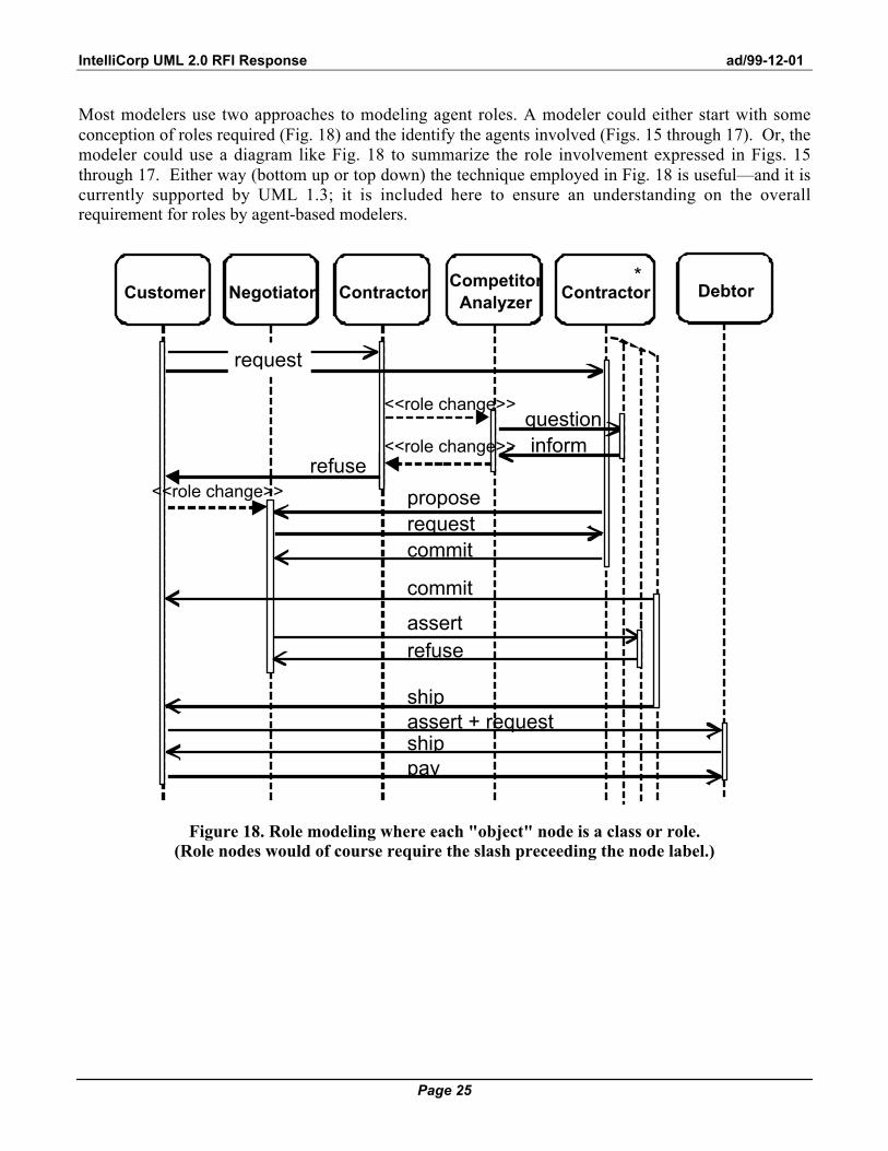
Most modelers use two approaches to modeling agent roles. A modeler could either start with someconception of roles required (Fig. 18) and the identify the agents involved (Figs. 15 through 17). Or, themodeler could use a diagram like Fig. 18 to summarize the role involvement expressed in Figs. 15through 17. Either way (bottom up or top down) the technique employed in Fig. 18 is useful—and it iscurrently supported by UML 1.3; it is included here to ensure an understanding on the overallrequirement for roles by agent-based modelers.
Negotiator Contractor
assert + request
pay
Contractor
request
questioninform
refuse
refuse
propose
commit
commit
assert
ship
ship
request
CustomerCompetitor
AnalyzerDebtor
<<role change>>
<<role change>>
<<role change>>
*
Figure 18. Role modeling where each "object" node is a class or role.(Role nodes would of course require the slash preceeding the node label.)

IntelliCorp UML 2.0 RFI Response ad/99-12-01
Page 26
Collaboration diagrams currently have no facility to represent agent roles on interaction lines withinUML 1.3. However, each communication act (or message) could be labeled with the role that isresponsible for issuing the request. (Note: the usage of the guillemot in Fig. 19 is not orthodoxaccording to UML 1.3; however, no existing technique yet exists to label interaction lines with thesender's role indication.) This technique is illustrated in Fig. 19. For example, communication act 1.1request is sent by agent A playing the role of Customer.
1.3: request<<role: customer>>
12: assert + request<<role: customer>>
14: pay<<role: customer>>
2: question
3: inform
4: refuse
5: propose 7: commit10: refuse
8: commit11: ship13: ship
1.1: request<<role: customer>> 1.2: request
<<role: customer>> 6: request
<<role: negotiator>> 9: assert
<<role: negotiator>>
B :
A :
C :
D :
Figure 19. Role modeling where communication acts (messages) indicate the requesting role.
Activity diagrams can also be modified to represent agent roles by associating each activity with thename of the appropriate ClassifierRole. For example in Fig. 20, an Order agent accepts, assembles,ships, and closes orders.
(Order) (Order) (Order) (Order)
(Payment)(Invoice)
OrderAccept
OrderClose
OrderShip
OrderAssemble
PaymentProcess
PaymentSend
InvoiceSend
(Customer)
Figure 20. An activity diagram with activities labeled with the appropriate agent role.

IntelliCorp UML 2.0 RFI Response ad/99-12-01
Page 27
And lastly, changes in roles can be represented on activity diagrams using notes. For example in Fig.21, the Hire Employee activity changes the role of an agent from being a Person to also being anEmployee. Such a technique also currently supported by UML; it is included here to ensure anunderstanding on the overall requirement for roles by agent-based modelers.
<<Role change (classify)FROM Person
TO Person and Employee>>
PromoteEmployee
HireEmployee
Employeehired
Employeepromoted
<<Role change (classify)FROM Person and Employee
TO Person, Employee, and Manager>>
• • • • • •
Figure 21. Dynamic classification (role changes) expressed as notes.
8.2. Package extension
UML 1.3 employees "lollypops" to indicated interfaces. While this will suffice for some agentimplementations, it will not handle those situations where the agent—itself—is the interface. Forexample, a cell membrane receives various "communications" and processes them by rejecting them oraccepting them. There is not interface set that a cell publishes to the outside world. A similar analogy isapplied in many agent-based implementations. For example in Fig. 22, a Negotiator agent acts as theinterface between the outside world and the Manufacturing Cell. This would require a small extensionto UML.
interfaceagent
NegotiatorAgent
• • •
ManufacturingCell
CommonFunctionAgents
ResourceAgent Resource
0..*
1..*
an aggregate
CommonFunctionAgents
ProcessPlanning
Agent
CapacityManager
Agent
AccountManager
Agent
1..
0..
DispatchAgent
• • •
telescopingagent
packages
Figure 22. Package specifying agents instead of operations as interface points.

IntelliCorp UML 2.0 RFI Response ad/99-12-01
Page 28
8.3. Deployment diagram extensions
Mobility is an important agent property—as it is for objects , as well. A way of indicating mobilitypaths and at-home declarations would be a useful extension to UML.
SalesWeb Internet server
Accountingmainframe
Inventorymainframe
CorporateNovell
Network/SQL
Internet
SalesAgent
ShopperAgent
Salesperson'slaptop
ShopperAgent
<<at-home>>
<<mobile>>
Figure 23. Adding mobility to deployment diagrams.
8.4. Other useful agent-based notions
Agents borrow many analogies from nature. Agent-based researchers reason that if it took nature 3billion years to develop what we now see in the modern world, perhaps we could learn some lessonsabout building our own systems.
Dolly:Sheep
Dolly2:Sheep
<<clone>><<prototype>>
Class Diagram
Dolly:Sheep
Dr_Frankenstein:Scientist
Dolly2:Sheep
get specs
<<clone>>
Sequence Diagram
Figure 24. Representing cloning using sequence and class diagrams.

IntelliCorp UML 2.0 RFI Response ad/99-12-01
Page 29
For example, agent cloning is a common agent-based technique. Figure 24 illustrates a behavioral and astructural view of agent cloning. Mitosis and reproduction are also common techniques for agent-basedsocieties. Figure 25 illustrates possible ways of expressing these. Extending the UML to include thesenotion permanently instead of by stereotype is a recommendation as these are common techniques. IfOO approaches determine that such notions are not useful, perhaps they belong in a an Agent Profile.
A:Amoeba
A1:Amoeba
<<mitosis>>
A2:Amoeba
Mitosis
Sequence Diagram
Junior:Starfish
John:Starfish
Janet:Starfish
<<reproduction>>
Bisexual
Collaboration Diagram
Figure 25. Representing mitosis and reproduction using sequence and activity diagrams.
Other notions that are commonly employed for agents are parasitic and symbiotic relationships. Figure26 illustrates some examples of these,
Dog
Flea
0..*
0..*
<<host/parasite>>
Tree
Epiphyte
0..*
1
<<symbiosis>>
Figure 26. Representing parasitic and symbiotic relationships using class diagrams.
The interaction of many individual agents can give rise to secondary effects where groups of agentsbehave as a single entity, or aggregate agent. This phenomenon is know as emergence. While suchoccurrences are often unplanned and unexpected, they should be anticipated. In multiagent systems,emergence is a core concept. As such, a way of representing it is important.
Market
Consumer
0..*
0..*
<<emergence>>
Figure 27. Representing emergence possibilities using a class diagram.

IntelliCorp UML 2.0 RFI Response ad/99-12-01
Page 30
9. CONCLUSION
UML provides tools for :
• specifying agent interaction protocols as a whole, as in [28];• expressing the interaction pattern among agents within a protocol, as in [1, 8, 21]; and• representing the internal behavior of an agent, as in [27].• representing other agent-related UML extensions that are already commonly used, such as richer role
specification, packages with agent interfaces, deployment diagrams indicating mobility, and othertechniques.
Some of these tools can be applied directly to agent-based systems by adopting simple idioms andconventions. In other cases, we suggest several straightforward UML extensions that support theadditional functionality that agents offer over the current UML version 1.3. Many of these proposedextensions are already being considered by the OO community as useful extensions to OO developmenton UML version 2.0. Furthermore, many of the AUML notions presented here were developed andapplied within the MoTiV-PTA projects [http://www.motiv.de/], an agent-based realization of a personaltravel assistant, supported by the German Ministry of Technology.
Agent researchers can be gratified at the increasing attention that industrial and business usersare paying to their results. The transfer of these results to practical application will be more rapid andaccurate if the research community can communicate its insights in forms consistent with modernindustrial software practice. AUML builds on the acknowledged success of UML in supportingindustrial-strength software engineering. The idioms and extensions proposed here for AIP’s—as well asothers that we are developing—are a contribution to this objective.

IntelliCorp UML 2.0 RFI Response ad/99-12-01
Page 31
REFERENCES
1. Bauer, B., Extending UML for the Specification of Interaction Protocols, submitted for the 6th Callfor Proposal of FIPA, 1999.
2. Bauer, B., Extending UML for the Specification of Interaction Protocols, submitted to ICMAS 2000,2000.
3. Booch, Grady, James Rumbaugh, and Ivar Jacobson, The Unified Language User Guide, Addison-Wesley, Reading, MA, 1999.
4. Brazier, Frances M.T., Catholijn M. Jonkers, and Jan Treur, ed., Principles of Compositional Multi-Agent System Development Chapman and Hall, 1998.
5 . Bryson, Joanna, and Brendan McGonigle, "Agent Architecture as Object Oriented Design,"Intelligent Agents IV: Agent Theories, Architectures, and Languages. Proceedings of ATAL'97., ed.,Springer, Berlin, 1998.
6. Burmeister, B., ed., Models and Methodology for Agent-Oriented Analysis and Design 1996.7 . Burmeister, Birgit, Afsaneh Haddadi, and Kurt Sundermeyer, ed., Generic, Configurable,
Cooperation Protocols for Multi-Agent Systems Springer, Neuchâtel, Switzerland, 1993.(Programmable model of interaction)
8. Ferber, Jacques, Multi-Agent Systems: An Introduction to Distributed Artificial Intelligence, AddisonWesley Longman, Harlow, UK, 1999.
9. Garijo, Francisco J., and Magnus Boman ed., Multi-Agent System Engineering: Proceedings ofMAAMAW'99, Springer, Berlin, Germany, 1999.
10. Gustavsson, Rune E., "Multi Agent Systems as Open Societies," Intelligent Agents IV: AgentTheories, Architectures, and Languages, ed., Springer, Berlin, 1998.
11. Herlea, Daniela E., Catholijun M. Jonker, Jan Treur, and Niek J.E. Wijngaards, ed., Specification ofBehavioural Requirements within Compositional Multi-Agent System Design Springer, Valencia,Spain, 1999.
12. Iglesias, Carlos A., Mercedes Garijo, and José C. González, ed., A Survey of Agent-OrientedMethodologies University Pierre et Marie Curie, Paris, FR, 1998.
13. Iglesias, Carlos A., Mercedes Garijo, José C. González, and Juan R. Velasco, "Analysis and Designof Multiagent Systems using MAS-CommonKADS," Intelligent Agents IV: Agent Theories,Architectures, and Languages, Munindar P. Singh et al. ed., Springer, Berlin, 1998, pp. 313-328.
14. Jonker, Catholijn M., and Jan Treur, ed., Compositional Verification of Multi-Agent Systems: aFormal Analysis of Pro-activeness and Reactiveness Springer, 1997.
15. Kinny, David, and Michael Georgeff, "Modelling and Design of Multi-Agent Systems," IntelligentAgents III: Proceedings of the Third International workshop on Agent Theories, Architectures, andLanguages (ATAL'96), ed., Springer, Heidelberg, 1996.
16. Kinny, David, Michael Georgeff, and Anand Rao, "A Methodology and Modelling Technique forSystems of BDI Agents," Agents Breaking Away. 7th European Workshop on ModellingAutonomous Agents in a Multi-Agent World (MAAMAW'96)., Walter VandeVelde and John W.Perram ed., Springer, Berlin, 1996, pp. 56-71. .
17. Lee, Jaeho, and Edmund H. Durfee, "On Explicit Plan Languages for Coordinating Multiagent PlanExecution," Intelligent Agents IV: Agent Theories, Architectures, and Languages, ed., Springer,Berlin, 1998, pp. 113-126.

IntelliCorp UML 2.0 RFI Response ad/99-12-01
Page 32
18. Martin, James, and James J. Odell, Object-Oriented Methods: A Foundation, (UML edition),Prentice Hall, Englewood Cliffs, NJ, 1998.
19. Nodine, Marian H., and Amy Unruh, "Facilitating Open Communication in Agent Systems: theInfoSleuth Infrastructure," Intelligent Agents IV: Agent Theories, Architectures, and Languages,Munindar P. Singh et al. ed., Springer, Berlin, 1998, pp. 281-296.
20. Odell, James ed., Agent Technology, OMG, green paper produced by the OMG Agent WorkingGroup, 1999.
21. Parunak, H. Van Dyke, ed., Visualizing Agent Conversations: Using Enhanced Dooley Graphs forAgent Design and Analysis 1996.
22. Parunak, H. Van Dyke, and James Odell, Engineering Artifacts for Multi-Agent Systems, ERIMCEC, 1999.
23. Parunak, H. Van Dyke, John Sauter, and Steven J. Clark, "Toward the Specification and Design ofIndustrial Synthetic Ecosystems," Intelligent Agents IV: Agent Theories, Architectures, andLanguages, Munindar P. Singh et al. ed., Springer, Berlin, 1998, pp. 45-59.
24. Rumbaugh, James, Ivar Jacobson, and Grady Booch, The Unified Modeling Language ReferenceManual, Addison-Wesley, Reading, MA, 1999.
25. Schoppers, Marcel, and Daniel Shapiro, "Designing Embedded Agents to Optimize End-UserObjectives," Intelligent Agents IV: Agent Theories, Architectures, and Languages, Munindar P.Singh et al. ed., Springer, Berlin, 1998, pp. 3-14.
26. Singh, Munindar P., "A Customizable Coordination Service for Autonomous Agents," IntelligentAgents IV: Agent Theories, Architectures, and Languages, Munindar P. Singh et al. ed., Springer,Berlin, 1998, pp. 93-106.
2 7 . Singh, Munindar P., ed., Developing Formal Specifications to Coordinate HeterogeneousAutonomous Agents IEEE Computer Society, Paris, FR, 1998.
28. Wooldridge, Michael, Nicholas R. Jennings, and David Kinny, "The Gaia Methodology for Agent-Oriented Analysis and Design," International Journal of Autonomous Agents and Multi-AgentSystems, 3:Forthcoming, 2000.