Embed Size (px)
Citation preview

HAL Id: pastel-00004086https://pastel.archives-ouvertes.fr/pastel-00004086
Submitted on 6 Nov 2008
HAL is a multi-disciplinary open accessarchive for the deposit and dissemination of sci-entific research documents, whether they are pub-lished or not. The documents may come fromteaching and research institutions in France orabroad, or from public or private research centers.
L’archive ouverte pluridisciplinaire HAL, estdestinée au dépôt et à la diffusion de documentsscientifiques de niveau recherche, publiés ou non,émanant des établissements d’enseignement et derecherche français ou étrangers, des laboratoirespublics ou privés.
La Synthèse MPSoC et NoC avec Customisation desExtensions SIMD
Muhammad Omer Cheema
To cite this version:Muhammad Omer Cheema. La Synthèse MPSoC et NoC avec Customisation des Extensions SIMD.domain_stic. Université Paris Sud - Paris XI, 2008. Français. <pastel-00004086>

N° D’ORDRE
UNIVERSITE PARIS-SUD XI Faculté des Sciences d’Orsay
ECOLE NATIONALE SUPERIEURE DE TECHNIQUES AVANCEES
THÈSE DE DOCTORAT SPECIALITE : PHYSIQUE
Ecole Doctorale « Sciences et Technologies de l’Information des Télécommunications et des Systèmes »
Présentée par : Mr Muhammad Omer CHEEMA
Sujet :
La Synthèse MPSoC et NoC avec Customisation des
Extensions SIMD
Soutenue le 20 Juin 2008 devant les membres du jury :
M BOURENNANE El-bey Rapporteur, Professeur, Université de Bourgogne, France
M GRANADO Bertrand Professeur, Université Pierre et Marie Curie, France
M HAMMAMI Omar Co-directeur de Thèse, Enseignant-chercheur, ENSTA, France
M LACASSAGNE Lionel Maitre de Conférences, Université Paris-Sud, Orsay, France
M MARTIN ERIC Professeur, Université de Bretagne Sud, Lorient France
M MERIGOT Alain Directeur de Thèse, Université Paris-Sud, Orsay, France

Acknowledgements
I would like to extend my deepest gratitude and appreciation to my advisors Alain
Merigot, Omar Hammami and Lionel Lacassagne at IEF and ENSTA. Guidance and
instruction of Mr Omar Hammami has played an invaluable part in both my graduate
studies and PhD Work. I will specially like to thank Mr. Alain Sibille for his efforts of
creating and maintaining an excellent research environment at LEI, ENSTA.
It has been a pleasure to work with my colleagues at IEF and ENSTA Paris. They have
provided a friendly, encouraging, and supportive environment for me to work in. I will
specially like to thank Asad Mahmood, Taj Muhammad Khan and Husnain Mansoor Ali
for being there with me to help me at all difficult moments and sharing their experiences
in all ups and downs during these three and a half years.
I am very thankful to my reviewers Habibullah Jamal and El-Bay Bourennane for
helping me improve my manuscript and for providing me valuable feedback on my
research work. I am honoured to have Eric Martin and Bertrand Granado on my PhD
jury and I am thankful to them for accepting to be a part of it.
Finally I would like to recognize the best family anyone could ever ask for, especially
my parents who put the spirit of learning and research in my personality from very
beginning of my school till this time. The work done in this thesis is a result of their
indirect efforts and sacrifices they have made during whole of my childhood and youth.
It would have never been possible without their unconditional love, support and
understanding.

MPSoC Synthesis with Customized SIMD Instruction Set Extensions 3
Abstract:
An efficient system level design methodology for MPSoC synthesis should be able to
exploit both coarse grained and fine grained parallelism inherent in the target application.
Traditional MPSoC synthesis methodologies proposed so far emphasize on coarse grained
(task level) parallelism exploitation where processor cores architecture is fixed before the
start of multiprocessor design. On the other hand, extensible processor synthesis
methodologies emphasize on fine grained (instruction level) parallelism ignoring the task
level parallelism exploitation through multiprocessor design. We have observed that the
problems of processor extension synthesis and general MPSoC synthesis are closely related
and it is important to integrate both problems together to get optimal result. However,
combining both problems complicates the synthesis even more because of large design
spaces associated with these problems. In this thesis, we have proposed an MPSoC design
methodology that combines the problem of traditional MPSoC synthesis with extensible
processor synthesis to take benefit of both levels of parallelism.
Our contribution to the thesis can be divided into three main parts:
1. At first, we propose a methodology to automatically generate custom SIMD extended processors. In our approach, instruction selection and matching process is simplified by limiting the instruction to SIMD extensions hence reducing the design space for the problem without compromising on the performance of results.
2. In second step, we propose a methodology to explore multiprocessor system on chip design space at systemC transaction level. Contrary to existing approaches, our methodology introduces area and energy estimation in the design flow at early stages of system design resulting in a better understanding for HW/SW design tradeoffs for system designers.
3. Last part of the thesis combines both above mentioned methodologies of extensible processor synthesis and MPSoC synthesis together so that instruction level parallelism and task level parallelism can be exploited inside an integrated framework. As a result, each processor in an MPSoC environment can be suitably extended according to the task mapped on it and network on chip design parameters can be adjusted based on the effects of custom processor extensions of each of the processors in the system.
Results obtained by applying our methodology for design of various image processing
applications show the benefits of our proposed approach.

MPSoC Synthesis with Customized SIMD Instruction Set Extensions 4
Résumé:
Une méthode de conception de niveau de système efficace de synthèse MPSOC devrait
être capable d'exploiter à la fois les parallélismes à gros grains et à grains fins inhérents à
l'application cible. Les méthodes de synthèse traditionnelles ont jusqu’à lors proposé de
mettre l’accent sur l’exploitation de parallélismes à gros grains (niveau des tâche) dans
lesquelles l’architecture des cœurs de processeurs est définie avant le début de la
conception des multiprocesseurs. D’un autre côté, des méthodologies de synthèse de
processeur étendus portent leur attention sur les parallélismes à grains fins (niveau
d’instruction) en ignorant l'exploitation des parallélismes de niveau des tâches par la
conception de multiprocesseurs. Nous avons observé que les problèmes de synthèse
d’extension de processeur et la synthèse général MPSoc sont étroitement reliés et il est
important d’intégrer les deux problèmes ensemble pour obtenir un résultat optimal.
Cependant, la combinaison des deux problèmes complique beaucoup plus la synthèse à
cause des grands espaces de conception associés avec ces problèmes. Dans cette thèse,
nous avons proposé une méthodologie de conception MPSoC qui combine le problème de
synthèse MPSoC traditionnelle avec la synthèse de processeur étendu pour bénéficier des
deux niveaux de parallélisme.
Notre contribution à la thèse peut être divisée en trois parties principales:
1. En premier lieu, nous proposons une méthodologie pour générer automatiquement des processeurs étendus de SIMD programmable. Dans notre approche, la sélection d’instruction et l’association de processus sont simplifiés par la limitation des instructions aux extensions SIMD, donc en réduisant l’espace de conception pour le problème sans compromettre les résultats de performance.
2. En second lieu, nous proposons une méthodologie pour explorer l’espace de conception d’un système de multiprocesseur sur puce au niveau de transaction de systemC. Contrairement aux approches existantes, notre méthodologie introduit des estimations d’espace et d’énergie dans le flux de conception à des étapes précoces de conception du système. Ce qui conduit à une meilleure compréhension des compromis de conception HW/SW pour les concepteurs de système.
3. La dernière partie de la thèse combine ensemble les deux méthodologies mentionnées ci-dessus, soit la synthèse de processeur étendu et la synthèse MPSoC de telle sorte que le parallélisme de niveau d’instruction et le parallélisme de niveau de tâche peuvent être exploités au sein d’un système intégré. Il en résulte que chaque processeur dans un environnement MPSoC peut être étendu d’une manière appropriée selon la tâche qui lui est associée et les paramètres de conception de réseau sur puce peuvent être ajustés sur la base des effets des extensions de processeur programmables des processeurs dans le système.

MPSoC Synthesis with Customized SIMD Instruction Set Extensions 5
Table of Contents
Acknowledgements 2
1. Les Synthèses MPSoC et NoC avec Programmation des Extensions SIMD 11
1.1 Introduction 11
1.2 Motivation 13
1.3 Etude en relation 15 1.3.1 La Synthèse de Processeur Etendu 15
1.3.2 Les Synthèses MPSoC et NoC 17
1.4 Vue d’Ensemble du Problème 19
1.5 Méthodologie de Synthèse d’Unité SIMD Programmable 21 1.5.1 Auto-Vectorisation et Classes d’Equivalence 22
1.5.2 Analyse Statique et Résultats de Profilement 24
1.5.3 Génération du Module AltiVec 25
1.5.4 Exécution du Temps Réel sous Virtex- 4 FPGA 25
1.6 Expériments et Résultats pour la Méthode de Synthèse des Extensions du Monoprocesseur SIMD 26
1.7 Le Flux de Conception de la Méthode de Synthèse MPSoC proposée 31
1.8 Organisation Expérimentale 35
1.9 Résultats Et Discussion 38
1.10 Conclusions 44
References 45
2. Motivation 48
2.1 Embedded systems 50
2.2 Embedded System Design methodologies 52 2.2.1 A Brief History of Embedded System Design Methodologies 52
2.2.2 Architectural Classification of Embedded Systems 54
2.3 Major Issues in ASIP and MPSoC Synthesis 57 2.3.1 ASIP Design Key Issues and Methodologies 57
2.3.2 Overview of MPSoC Design Problem 60
2.4 Organization of the Thesis: 63

MPSoC Synthesis with Customized SIMD Instruction Set Extensions 6
3. Embedded Processor Customization 66
3.1 Related Work 68
3.2 Study of Utilization of AltiVec Units 71 3.2.1 An Overview of AltiVec 71
3.2.2 Vector Integer Instructions 74
3.2.3 Vector Shift and Rotate Instructions 76
3.2.4 Vector Permutation and Formatting Instructions 77
3.2.5 Vector Floating Point Instructions 80
3.2.6 Miscellaneous Instructions 81
3.3 Utilization rate 81
3.4 Adaptive Generation of SIMD Units 84 3.4.1 Auto-Vectorization and Equivalence Classes 85
3.4.2 Static Analysis and Profiling Results 87
3.4.3 AltiVec Module Generation 88
3.4.4 Real time execution over Virtex- 4 FPGA 88
3.5 Experimental Setup 89
3.6 Evaluation Results 91
3.7 Conclusions 96
4. System Level Design Space Exploration 99
4.1 Platform Based TLM Design Process 101 4.1.1 IBM’s Platform Driven Design Methodology 102
4.1.2 PowerPC Evaluation Kit 108
4.2 Behavioral Synthesis 111 4.2.1 Orinoco Dale: A Brief Introduction 112
4.3 Introducing Power Estimation in High Level TLM Design Flow: A Case Study 113 4.3.1 Power Estimation: Related Work 114
4.3.2 Area/Energy Estimation Extension to Traditional TLM Design Flow 116
4.3.3 Experiment Environment and Results 122
4.3.4 Summarizing the Case Study 125
4.4 A Platform based TLM Level Design Methodology for Multimedia Application Synthesis 126
4.5 Applications in Intelligent Vehicle Systems: A Case Study 129 4.5.1 Related Work 131
4.5.2 Evaluation results 135
4.5.3 Extensions: Combining UML based System design flow with SystemC TLM platform for
intelligent vehicles Design 141
4.6 Conclusions 145
MPSoC Synthesis with Customized SIMD Instruction Set Extensions 7
5. MPSoC and NoC Synthesis with Custom SIMD Extensions 149
5.1 Introduction 150
5.2 Motivation 151
5.3 Related Work 153
5.4 Problem Overview 156
5.5 Design Flow of Proposed Methodology 158 5.5.1 Mapping Problem 160
5.5.2 Custom SIMD Instruction Set Extended Processor Generation 161
5.5.3 Network Simplification 161
5.6 Experimental Setup 162
5.7 Results and Discussion 164
5.8 Conclusions 171
References 171
6. Conclusions and Perspective 175
6.1 Summary of the Thesis 175
6.2 Future Research Directions 176

MPSoC Synthesis with Customized SIMD Instruction Set Extensions 8
List of Figures
Figure 1-1 Classification des Parallélismes au sein des Systèmes Embarqués ............................................ 14 Figure 1-2 Intégration d’Instructions Etendues avec la Synthèse MPSoC en utilisant des Flux de
Conception Traditionnels ....................................................................................................................... 20 Figure 1-3 Flux de Conception de Système .................................................................................................... 22 Figure 1-4 Espace des Modules AltiVec Modules dans Virtex-4 .................................................................. 27 Figure 1-5 Compromis entre Espace et Accélération pour un Programme de Matrice Transposée......... 28 Figure 1-6 Compromis entre Espace et Accélération pour des filtres moyens............................................ 30 Figure 1-7 Compromis entre Taille d’Image et Accélération pour des Filtres Moyens ............................. 30 Figure 1-8 Méthodologie de Conception MPSoc pour un Processeur SIMD étendu avec un NoC sous-
jacent ........................................................................................................................................................ 32 Figure 1-9 PowerPC 750 étendu avec un jeu d’Instruction AltiVec ........................................................... 36 Figure 1-10 Un Réseau sur Puce typique modélisé en utilisant notre système. ........................................... 38 Figure 2-1 Impact of Design Technology on SoC Implementation Cost...................................................... 49 Figure 2-2 Comparison of Various Architectural Paradigms ...................................................................... 55 Figure 2-3 Generalized ASIP Design Flow..................................................................................................... 58 Figure 2-4 A Sample MPSoC Architecture .................................................................................................... 61 Figure 2-5 Classification of Communication Architectures.......................................................................... 62 Figure 3-1 PowerPC G4 Architecture........................................................................................................... 72 Figure 3-2 AltiVec Architecture: A System Level View.............................................................................. 74 Figure 3-3 vmladduhm: Multiply-Add of Eight Integer Elements (16-Bit)............................................... 76 Figure 3-4 AltiVec Shift Instruction ............................................................................................................. 77 Figure 3-5 AltiVec Merge Instruction........................................................................................................... 78 Figure 3-6 AltiVec Pack Instruction .............................................................................................................. 78 Figure 3-7 AltiVec Unpack Instruction ........................................................................................................ 78 Figure 3-8 AltiVec Vector Permute Instruction........................................................................................... 80 Figure 3-9 Target Architecture ..................................................................................................................... 85 Figure 3-10 System Design Flow ................................................................................................................... 85 Figure 3-11 PowerPC with APU Interface .................................................................................................... 89 Figure 3-12 Xilinx ML403 FPGA Resources................................................................................................ 90 Figure 3-13 Area of AltiVec Modules in Virtex-4........................................................................................ 92 Figure 3-14 Area vs. Speedup Trade-off for Matrix Transpose Program................................................. 93 Figure 3-15 Area vs. Speedup Trade-off for Average Filters ...................................................................... 95 Figure 3-16 Image Size vs. Speedup Trade-off for Average Filters ........................................................... 95 Figure 4-1 Transaction Level Modeling vs Register Transfer Level........................................................ 100 Figure 4-2 IBM CoreConnect Platform...................................................................................................... 102 Figure 4-3 SystemC System Design Flow ................................................................................................... 103 Figure 4-4 PowerPC 405 block diagram for the PEK SoC design ............................................................ 109 Figure 4-5 Graphical Modeling Using CBSLD ........................................................................................... 110

MPSoC Synthesis with Customized SIMD Instruction Set Extensions 9
Figure 4-6 Generalized Behavioral Synthesis Flow ................................................................................... 112 Figure 4-7 Behavioral Synthesis Flow using Orinoco Dale ....................................................................... 113 Figure 4-8 Target Platform Built using IBM TLM .................................................................................... 116 Figure 4-9 HW/SW Codesign Flow............................................................................................................. 117 Figure 4-10 Implementing Transaction Read and Write Functions on Slave Hardware Accelerators 119 Figure 4-11 Transforming SW Computation into Communication Tasks .............................................. 121 Figure 4-12 Control Data Flow Graph of Filters in the Application......................................................... 122 Figure 4-13 Energy consumption requirements for filters........................................................................ 123 Figure 4-14 Area requirements for filters .................................................................................................. 124 Figure 4-15 Execution cycles taken by Filters............................................................................................ 124 Figure 4-16 Heat Maps of Filters ................................................................................................................ 124 Figure 4-17 Harris Corner Detector Chain................................................................................................. 127 Figure 4-18 Freescale MPC controllers (a) MIPS/Embedded RAM....................................................... 131 Figure 4-19 Freescale MPC controllers (b) MPC 565 Block Diagram..................................................... 132 Figure 4-20 V Design Cycle.......................................................................................................................... 134 Figure 4-21 Decomposition ........................................................................................................................... 134 Figure 4-22 HW vs. SW Performance of Operators................................................................................... 137 Figure 4-23 a) Platform configuration 7 (b) full HW/SW Design Space Exploration Results ................. 139 Figure 4-24 Various Cache Sizes and System Performance ..................................................................... 140 Figure 4-25 Platforms networked through CAN bus ................................................................................. 140 Figure 4-26 Accord/UML Design Methodology ........................................................................................... 142 Figure 4-27 UML/SysML/TLM SystemC Platform Based design Methodology for Intelligent Vehicles
................................................................................................................................................................ 144 Figure 5-1 Classification of parallelism in Embedded Systems................................................................. 152 Figure 5-2 Integrating Extensible Instructions with MPSoC Synthesis using Traditional Design Flows
................................................................................................................................................................ 157 Figure 5-3 MPSoC Design Methodology for SIMD extended processor with an underlying NoC........ 159 Figure 5-4 PowerPC 750 extended with AltiVec Instruction Set............................................................. 163 Figure 5-5 A typical Network on Chip modelled using our framework .................................................. 164
Figure 5-6 Image Processing Chain to be Synthesized .............................................................................. 164 Figure 5-7 Area of AltiVec Modules on Virtex-IV FPGA......................................................................... 166

MPSoC Synthesis with Customized SIMD Instruction Set Extensions 10
List of Tables
Table 1-1 Espace vs. Accélération pour Programme de Matrice Transposée 28 Table 1-2 Espace vs. Accélération pour des Filtres Moyens 29 Table 1-3 Résultats des Synthèses pour une Chaîne de Détecteur Harris Corner 40 Table 1-4 Comparaison des Performances des Opérateurs dans les Versions HW, SIMD et GPP 40 Table 1-5 Accélération du système de Monoprocesseur étendu SIMD vs. Processeur à But Général 41 Table 1-6 Résultats des Performances pour Diverses Configurations MPSoC 43 Table 2-1 Design Requirements for Major Embedded Product Groups 51 Table 3-1 Statistics (Idle Times and Events) ofG4 Functional Units executing Multimedia Applications 82 Table 3-2 Statistics (Idle Times and Events) of G4 Functional Units for different Data Sizes 83 Table 3-3: Area vs. Speedup for Matrix Transpose Program 93 Table 3-4 Area vs. Speedup for Average Filters 94 Table 4-1 Various configurations and Speed ups for Filters 125 Table 4-2 Synthesis Results for Harris Corner detector Chain 136 Table 4-3 Various configurations and Speedups for Point of Interest Detection 138 Table 5-1 Synthesis Results for Harris Corner detector Chain 167 Table 5-2 Performance Comparison of Operators in HW, SIMD and GPP Versions 167 Table 5-3 Speedup of SIMD Extended Monoprocessor system vs. General Purpose Processor 168 Table 5-4 Performance Results for Various MPSoC Configurations 170

MPSoC Synthesis with Customized SIMD Instruction Set Extensions 11
1. Les Synthèses MPSoC et NoC avec Programmation
des Extensions SIMD
1.1 Introduction
Pour satisfaire les plus hautes exigences informatiques en termes d’applications
embarquées incorporées, les concepteurs de système transfèrent de plus en plus leur
attention vers la conception de système d’applications spécifiques de multiprocesseurs sur
puce (MPSoC). Les MPSOCS modernes incluent plusieurs éléments de traitement
comprenant des processeurs de but généraux, des processeurs de signal numériques, des
coprocesseurs et des composants matériel IP programmables pour exécuter des calculs
divers. En raison de l'hétérogénéité inhérente à l’application spécifique MPSoCs, les
modèles de communication entre ces éléments de traitement deviennent également de plus
en plus complexes. En conséquence, les architectures légalement autorisées de
communication à base de bus ont été dans l’incapacité de faire face à la complexité
croissante des communications sur puce en raison de leur faible adaptabilité, tant en termes

MPSoC Synthesis with Customized SIMD Instruction Set Extensions 12
d’efficacité que de performance. Ainsi, les architectures de communication basées sur un
réseau structuré sur puce (NoC) ont remplacé les architectures sur diffusions (globales)
programmables et bus partagés. En raison de la complexité qui accompagne l’augmentation
toujours plus importante de nouvelles applications multimédia, on s’attend à ce que les
conceptions MPSoC et NoC deviennent encore plus complexes dans l’implication de
plusieurs cœurs de processeur en relation avec la communication et certains aspects de
développement d'applications. Développements qui exigeront la mise en place de nouvelles
méthodes de conception ayant comme principal objectif la résolution de problèmes liés à la
complexité, la productivité et l'efficacité du silicium [1].
Une approche différente pour réaliser une meilleure exécution à partir de ressources
limitées a été la synthèse de jeu d'instruction étendu. Dans cette approche, un processeur à
but général est étendu grâce aux instructions spécifiques définies au sein des modèles
trouvés dans le graphique de flux de données de l'application. En conséquence, les
séquences complexes d'instructions arrivant plus fréquemment dans un programme sont
remplacées par des instructions spécifiques ayant comme résultat d’augmenter d’une
manière significative la vitesse d’exécution du processeur avec une légère augmentation du
secteur et des besoins en énergie du processeur étendu.
La différence principale entre les approches mentionnées ci-dessus est que la synthèse
MPSOC exploite le parallélisme du niveau de tâche à gros grain inhérent à une application
alors que les méthodologies de la synthèse de processeur étendu ciblent les propriétés de
parallélisme du niveau de donnée à grain fin. Jusqu'à maintenant, la plupart des méthodes de
conception traditionnelles adressent seulement un niveau de parallélisme pour l'amélioration
de la performance. Pratiquement aucun travail n’a été réalisé pour adresser les parallélismes
à grain fin et à gros grain au sein d’une méthodologie impliquant en même temps la synthèse
de processeur étendu et la synthèse MPSoC. Dans ce chapitre, nous proposons une
méthodologie de conception de niveau système qui associe à la fois les deux niveaux de
parallélisme au sein d’un environnement intégré et définissons à partir de là un flux de
conception pour la synthèse MPSoC dans laquelle chaque processeur à but général est
étendu avec un ensemble d’instructions étendues appropriées en même temps qu’une

MPSoC Synthesis with Customized SIMD Instruction Set Extensions 13
configuration de tâche/tâches planifiées. Nos expériences démontrent qu’avant d’augmenter
la complexité de MPSoC et de NoC afin de respecter les contraintes de performance, un
effort devrait être réalisé pour utiliser le parallélisme du niveau de donnée à grain fin au sein
d’éléments de fonctionnement individuel utilisant des extensions de jeu d’instruction. Les
résultats montrent que notre approche réduit d’une manière significative la complexité de
MPSoC et de ses NoC associés sans compromettre de façon remarquable la performance de
l’application.
Le reste du chapitre est organisé de la manière suivante : La Section II décrit brièvement la
motivation de notre étude en expliquant les différents types de parallélismes inhérents aux
applications et aux architectures. La Section III présente l’étude en relation. La Section IV
présente une vue ensemble de la problème. Section V et VI sont dédié au méthodologie de
conception system monoprocesseur. La Section VII explique le flux de conception générale
de notre méthodologie de conception MPSoC suivi de l’Environnement expérimental et des
résultats obtenus dans les Sections VIII et IX. La Section X termine le chapitre et fait
allusion aux futurs travaux envisageables.
1.2 Motivation
Le choix d'exploiter le type approprié de parallélisme pour de futurs systèmes embarqués
a été un sujet d'intérêt particulier pour la communauté de recherche dans l'industrie et le
monde universitaire. L'image 1 classifie brièvement les types divers de parallélisme. Tandis
que les calculs superscalaires et les techniques de Pipelining ont excessivement été utilisés
au sein des architectures de processeur ayant comme objectif général la réalisation de haute
performance, l’industrie a commencé à voir les résultats de ses performances saturés avec
l’augmentation en complexité des pipelines et des architectures superscalaires. La
performance des architectures superscalaires dépend du parallélisme de niveau d’instruction
inhérent au programme et il est bien connu aujourd’hui [2] que la plupart des programmes
ont un degré moindre de parallélisme de niveau d’instruction ; ce qui affecte sévèrement
l’efficacité des architectures superscalaires en laissant plusieurs unités d’exécution sous
exploitées. De même, augmenter la profondeur du Pipeline est une tâche insignifiante en

MPSoC Synthesis with Customized SIMD Instruction Set Extensions 14
raison de longues pénalités de redémarrage lors des changements de flux de contrôle; ce qui
nécessite des mécanismes complexes tels que les prédictions de branchement et les
exécutions spéculatives. Les machines VLIW rencontrent le même problème que les
machines superscalaires avec en plus des questions de compilation impliquant la prédiction,
la compression de code, et faisant tourner les registres etc. En raison des goulots
d’étranglements rencontrés dans les architectures superscalaires, Pipelining et VLIW,
l’industrie a cherché des alternatives appropriées et de vifs intérêts pour le vecteur/SIMD,
l’utilisation de multiples processeurs et les techniques de lectures multiples sont alors
apparus.
Figure 1-1 Classification des Parallélismes au sein des Systèmes Embarqués
La plupart des applications très performantes au sein des systèmes embarqués modernes
telles que les applications multimédia et les DSP possèdent un degré élevé de parallélisme
de niveau de donnée à grain fin. Les architectures vectorielles et en particulier les
extensions de jeu d’instruction SIMD ont évolué afin d’être le mode d’exploitation de
parallélisme à grain fin préférable. En même temps, l’industrie de systèmes embarqués a
choisi le parallélisme à gros grain pour les architectures de multiprocesseurs sur puce time, à
cause du temps de commercialisation et des contraintes de productivité. Ces quelques
dernières années, plusieurs méthodes de conception de niveau de système ont été proposées
tant pour la synthèse MPSOC que pour la synthèse de jeu d'instruction extensible. Mais
malheureusement, presque toutes les méthodologies des synthèses se limitent à un seul
MPSoC Synthesis with Customized SIMD Instruction Set Extensions 15
niveau de parallélisme. A notre avis, limiter la méthodologie de conception au niveau de
parallélisme à gros grain complique inutilement l'architecture MPSOC dans le cas de la
synthèse MPSOC. D’autre part, mettre en avant le parallélisme de donnée à grain fin en
utilisant uniquement la synthèse de jeu d’instruction étendu s’avère parfois insuffisant
répondre aux besoins de performance. Il existe un besoin d’avoir des méthodes de
conception de niveau de système MPSoC qui adressent à la fois les deux niveaux de
parallélisme pour obtenir un maximum d’avantages des propriétés parallèles inhérentes à
chaque application. Dans ce chapitre, nous proposons une méthodologie pour la synthèse
MPSoC associé avec la génération de jeu d’instruction programmable qui exploite en même
temps les parallélismes à grain fin et à gros grain. Nous montrons qu’en intégrant des
instructions étendues programmables pour des tâches configurées au sein d’un processeur,
nous pouvons réduire la complexité du réseau du système afin d’obtenir à peu près le même
niveau de performance que celui qui pourrait être atteint avec un réseau sur puce complexe
impliquant un nombre élevé de cœurs de processeur.
1.3 Etude en relation
Notre étude dans ce chapitre associe deux domaines différents mais néanmoins très proches
au sein de la synthèse de niveau de système. Même si un grand nombre de travaux ont été
réalisés dans chacun des domaines individuellement, un petit nombre d’études ont été
réalisées en associant les deux domaines ensemble. Une brève vue d’ensemble du travail
réalisé est décrite ci-dessous.
1.3.1 La Synthèse de Processeur Etendu
Le problème des synthèses de processeur programmable optimisé pour un groupe
d’applications (ASIP) a été étudié pendant de nombreuses années. Dans [3] Keutzer et al.
ont présenté une vue d’ensemble des dernières tendances au sein de la conception ASIP. La
synthèse de jeu d’instruction implique des mécanismes de sélection et de mapping des
instructions ainsi que des améliorations micro architecturale au sein des processeurs étendus.
Une méthodologie pour synthétiser des instructions programmables et la microarchitecture

MPSoC Synthesis with Customized SIMD Instruction Set Extensions 16
est discutée dans [4] tandis que [5], [6] et [7] ciblent la performance de la synthèse ASIP
utilisant un compilateur recyclable pour les descriptions de matériel données.
Un nombre important de recherches ont été effectuées pour synthétiser les jeux
d’instruction étendus afin d’améliorer la performance d’un processeur de base ayant un jeu
d’instruction de base. Kucukcakar a décrit une méthodologie pour ajouter des instructions
programmables et modifier l’architecture ASIP [9]. Dans [11], l’approche basée sur des
heuristiques a été utilisée pour sélectionner des instructions programmables sous la
contrainte d’un espace de codage limité. Dans [12] et [13], une méthode automatique a été
proposée pour générer des instructions programmables utilisant des modèles d’opération, et
choisir l’instruction dans un budget de secteur. Cheung et al. ont proposé des techniques
pour la sélection d’instructions programmables, et associant un code d’application complexe
aux instructions programmables prédéfinies dans [14] et [15]. Un travail intéressant proposé
par Goodwin et Petkov met en exergue des techniques de génération d’instruction
programmable par l’identification d’opérations de style ‘très long mot définissant une
instruction’ (VLIW), d’opérations vectorielles, et d’opérations fusionnées [21]. Plusieurs
approches pour la génération d’instruction programmable sont basées sur l’identification des
flux de données – sous graphiques [16], [17], et de nombres symboliques [18]. Biswas et
Dutt ont présenté un heuristique pour synthétiser des instructions complexes pour des DSPs
ayant une connectivité hétérogène dans [19], et des techniques pour inclure des mémoires
localisées au sein d’instruction programmable dans [20]. Choi et al. ont analysé le problème
de la génération d’instructions complexes à partir d’instructions primitives comme un
problème de sous programmation modifiable dans [10]. L’étude effectuée dans [8] utilise
également de problème de sous programmation pour montrer que la consommations
d’énergie des ASIP’s est nettement réduite si le jeu d’instruction de base est choisi à partir
d’un processeur général tel que DSP. La technique pour synthétiser des processeurs
individuels dans ce chapitre est basée sur le travail effectué dans [22]. Ce travail cible des
applications de donnée intensives et utilise un sous programme d’extensions d’instruction
SIMD pour générer un processeur ASIP. Par conséquence, les temps de conception ASIP
sont significativement réduits sans compromettre les contraintes de performance et d’espace.

MPSoC Synthesis with Customized SIMD Instruction Set Extensions 17
D’un point de vue pratique, les standards SIMD ont aujourd’hui évolué et mûri de sorte que
les concepteurs ASIP ont accès à des environnements de développement ajusté, des
compilateurs, des algorithmes dédiées etc. Ce qui permet aux concepteurs de condenser
leurs efforts sur la conception ASIP plutôt que de se concentrer sur des problèmes triviaux et
connexes. Il en résulte une meilleure productivité qu’il peut être approprié d’utiliser au sein
d’une méthodologie intégrée pour les synthèses MPSoC.
1.3.2 Les Synthèses MPSoC et NoC
Beaucoup d’études ont été réalisées sur les synthèses MPSoC et NoC. Le problème des
synthèses peut grosso modo être divisé en deux problèmes : les synthèses d’architecture de
communication et de programmation. Les architectures de communication peuvent être des
architectures sur bus dans lesquelles une quantité significative de travail est effectué. Dans
[23], un outil de synthèse de connecteurs a été proposé pour synthétiser une architecture de
communication sur bus pour des systèmes MPSoC et différents types de connecteurs. De
Micheli a présenté une méthodologie de synthèse croisée dans [24] tandis que Nikil Dutt et
al. [25] ont récemment proposé une approche automatique pour synthétiser une architecture
de communication de matrice de connecteur sachant satisfaire les contraintes de
performance tout en réduisant la congestion du treillis dans la matrice. Une vaste littérature
est disponible sur les réseaux sur puce basés sur des synthèses d’architecture de
communication [26][27][28][29] qui sont reconnus pour être l’alternative aux architectures
sur bus existantes pour les futurs systèmes MPSoC impliquant des circuits de
communication complexes. Une enquête sur les méthodes existantes de conception de
réseaux sur puce a été proposée [30] alors que les problèmes existants et les challenges sont
décrits dans [31]. Diverses méthodologies sur les synthèses NoC ont été proposées dans
[32]-[41] et s’intéressent aux synthèses des structures NoC régulière et irrégulière.
L’approche basée sur des heuristiques a été utilisée [34] pour résoudre la contrainte
véhiculée par le problème de synthèse NoC dans lequel des contraintes ont été regroupées.
Ceci a été réalisé afin de réduire la surabondance de contraintes et ainsi une approche de
programmation quadratique est utilisée pour résoudre le problème de synthèse NoC sous des

MPSoC Synthesis with Customized SIMD Instruction Set Extensions 18
contraintes regroupées. Un algorithme pour associer un graphique de tâche à NoC est
proposé dans [35] pour minimiser l’énergie de communication. Les techniques de
programmation NoC pour les architectures MPSoC d’application spécifique sont discutées
en détail dans [36], [37],[38],[39]. Dans [40] est introduite une plateforme pour
l’exploitation de l’espace de conception utilisant des heuristiques et des simulations
thermiques, des partitions de réseaux ayant des contraintes de puissance et des
emplacements physiques de blocs de réseau. Les problèmes générés au niveau physique
pour optimiser les performances sont discutés dans [41]. Même si toutes ces méthodes
proposées s’adressent à des aspects importants des synthèses NoC et MPSoC, aucune des
études ne s’intéresse aux conséquences de la génération de micro architecture de processeur
simultanément avec l’exploration des espaces de conception MPSoC et NoC.
Des noyaux de soft (soft core) programmables fournissent aux concepteurs de système le
moyen de paramétrer l’architecture de processeur en même temps que la synthèse MPSoC.
Le travail effectué dans [42]-[45] adresse le problème de la programmation du noyau de soft
pour la synthèse MPSoC. Toutefois, les noyaux de soft paramétrés représentent un problème
différent de celui rencontré habituellement dans l’exploitation des unités programmables de
type “datapath” et dans l’accompagnement d’instruction programmable, comme cela est le
cas dans les processeurs programmables optimisés pour un groupe d’applications ASIP’s en
raison du nombre limité (ou « on/off ») de valeurs des paramètres.
Un travail encore plus récent réalisé par N.K Jha et al. [46] est probablement encore plus
proche de notre étude dans la mesure où il s’intéresse aux synthèses de processeur étendu
dans un environnement MPSoC. Cependant, leur méthodologie est restreinte aux
architectures de mémoire partagée et leurs plateformes cibles n’incluent pas les architectures
de communication à base de NoC. De plus, leurs systèmes synthétisés n’incluent pas les
synthèses de coprocesseur qui ont prouvées dans plusieurs cas être plus efficient que les
instructions programmables étendues. D’un autre côté, notre méthodologie s’intéresse aux
conséquences de la génération de matériel sur mesure et inclue la comparaison de la
performance de l’accélérateur matériel dédié avec un jeu d’instruction étendu au sein de
l’exploration de l’espace de conception. Nous avons également étudié l’impact de la

MPSoC Synthesis with Customized SIMD Instruction Set Extensions 19
génération d’instruction SIMD programmable sur la simplification de l’architecture de
communication (réseau sur puce), ce qui, selon nos meilleures sources, n’a pas été étudié
jusqu’à lors.
1.4 Vue d’Ensemble du Problème
Des soucis variés doivent être adressés dans une méthode intégrée pour la génération de
jeu d’instruction étendue avec des synthèses MPSoC. Les deux plus importants problèmes
sont expliqués ci-dessous.
Premièrement, le problème des synthèses MPSoC et des synthèses de processeur étendu
sont très résistants même s’ils sont pris en tant que deux problèmes séparés. Le problème de
synthèse MPSoC induit des sous problèmes de communication et de programmation de
synthèse d’architecture qui peuvent être plus loin décomposés en problème de
cloisonnement, d’allocation, de mapping et de programmation horaire si le co-design
HW/SW est considéré comme part du problème. De même, la synthèse de jeu d’instruction
étendu induit des sous problèmes de sélection de jeu d’instruction et d’association des
instructions qui eux-mêmes sont des problèmes d’une très grande complexité. Aussi
combiner les deux problèmes ensemble comme le suggère les flux de conception
traditionnel complexifie la problématique dans des limites inacceptables. Le problème
général des synthèses MPSoC combinées avec des synthèses d’instruction étendue a été
montré dans l’image 2. Comme cela est montré, un graphique de tâches est établi sur des
éléments en cours d’exécution au sein d’une architecture NoC dans lequel les extrémités
représentent la communication entre différents nœuds. Maintenant chaque tâche elle même
montre un degré de parallélisme de donnée à grain fin qui peut être exploité en utilisant des
extensions de jeu d’instruction étendues. Aussi en fonction de la décision de mapping prise
sur MPSoc, chaque processeur devrait être étendu avec des instructions programmables pour
obtenir de meilleure performance sur chaque nœud individuel. Mais tel que mentionné ci-
dessus, la solution du problème des synthèses combinées est très complexe. Et en raison des
contraintes de productivité, une meilleure méthodologie apportant un bon équilibre entre des

MPSoC Synthesis with Customized SIMD Instruction Set Extensions 20
résultats optimaux et la simplification de l’approche pour obtenir une meilleure productivité
est requise.
Extensible Instruction Synthesis for T4
MPY
XOR LD
XOR
SHR
XOR
MOVAND CUSTOM
General
Purpose
Processor
CustomHardware
LD
XOR SHR
Mapping of Tasks on an MPSoC Involving NoC
Figure 1-2 Intégration d’Instructions Etendues avec la Synthèse MPSoC en utilisant des Flux de
Conception Traditionnels
Deuxièmement, l’intégration des deux méthodologies révèle de nouvelles relations entre
différents paramètres. Par exemple, le mapping de décisions affecte fortement le jeu
d’instruction étendu à partir de l’architecture de processeur étendu. Ceci conduit à une
élévation du nombre de compromis espace/performance au sein de chaque nœud dans
MPSoC. La tâche de mapping de décisions affecte également le nombre et les circuits de
communications entre divers processeurs dans NoC. Cette situation met en avant le fait que
la tâche de mapping, la programmation du processeur et la configuration du réseau sur puce
ont des problèmes inter reliés. En tant qu’autre exemple, la performance d’un nœud peut
tellement augmenter après la génération d’un processeur étendue que le mapping de
décisions pourrait devenir sous optimale en demandant un nouveau mapping afin
d’équilibrer la charge de travail sur différents noeuds dans un réseau sur puce. Et quand le
nouveau re-mapping est accompli, des jeux d’instructions étendus pour chaque noeud

MPSoC Synthesis with Customized SIMD Instruction Set Extensions 21
doivent être re-générés, ce qui induit des boucles redondantes de plusieurs mapping et
génération de processeur étendu. A partir du niveau système, il est important de faire
apparaître un algorithme d’exploration qui peut adresser ces problèmes simultanément en
atteignant une solution optimale avec un nombre minimum d’itérations possible.
Notre méthodologie s’intéresse aux deux problématiques mentionnées ci-dessus. Pour
réduire la complexité du problème, nous simplifions le problème de jeu d’instruction en
introduisant un nouveau flux pour la synthèse SIMD programmable qui élimine les
problèmes de sélection de jeu d’instruction et de mapping d’instruction. Notre flux de
conception simplifié assure l’intégration des deux problèmes en traitant avec des paramètres
inter reliés d’une manière adéquate. Plus de détails sur notre flux de conception sont
expliqués dans les sections suivantes. Mais avant d’aller plus loin dans le détail de la
méthodologie de synthèse MPSoC, expliquons notre méthodologie d’extension de jeu
d’instruction de système SIMD programmable qui plus loin est à la base de la synthèse
MPSoC.
1.5 Méthodologie de Synthèse d’Unité SIMD Programmable
Notre flux de synthèse SIMD consiste à suivre les sous tâches décrites dans l’Image 3:
� Vectorisation
� Profilement Statique et Dynamique
� Génération du module AltiVec SIMD
� Exécution en temps réel de l’Application
� Répétition des étapes ci-dessus jusqu’à obtenir un jeu de solutions possibles .La
solution la plus en adéquation avec le demandes du système est retenue.

MPSoC Synthesis with Customized SIMD Instruction Set Extensions 22
Figure 1-3 Flux de Conception de Système
1.5.1 Auto-Vectorisation et Classes d’Equivalence
La nouvelle version de mise à jour de GCC 4.0.0 a une fonction d’auto-vectorisation.
L’optimiseur de code VAST a également prouvé être un outil utile d’optimisation. Nous
avons observé que pour qu’une application soit auto-vectorisable, l’écriture devrait garder à
l’esprit les possibilités d’auto-vectorisation, et utiliser un style de code qui peut
effectivement vectoriser le code. Normalement les adeptes de FORTRAN aiment coder les
résultats dans une meilleure vectorisation pour les outils existants. Les avantages offerts par
l’auto-vectorisation sont réduits si nous essayons de vectoriser une application qui n’a pas
été écrite en suivant un certain style de codage convenant à la vectorisation. C’est pourquoi
selon les techniques actuelles de vectorisation, nous croyons qu’il semble meilleur d’écrire
du code vectorisé qui est plus rapide que le code auto-vectorisé dans la plupart des cas. Et
après la vectorisation manuelle, la décomposition de l’instruction devrait être utilisée pour
programmer les unités SIMD. Il est important de noter ici que la décomposition est contraire
aux méthodes de synthèse de jeu d’instruction traditionnelles dans lesquelles les instructions
de processeur de but général sont fondues ensemble pour trouver des instructions
programmables. Pour l’objectif de la décomposition, nous avons défini des classes
d’équivalence d’AltiVec et des instructions PowerPC. Les classes d’équivalence

MPSoC Synthesis with Customized SIMD Instruction Set Extensions 23
représentent le remplacement possible d’une instruction par un jeu d’instruction
accomplissant la même opération. En conséquence, l’utilisation de certaines instructions
peut être évitée, ce qui pour nous a rendu possible le choix de composants alternatifs à
AltiVec et PowerPC afin de tester le comportement du système en cas de modification du
programme en utilisant une classe équivalente. Comme exemple très simple du concept de
classes d’équivalence, disons que nous avons une instruction vadduwm qui ajoute un vecteur
de quatre éléments ayant chacun une taille de 32-bit size. La description RTL de l’unité
SIMD est implémentée dans un module qui traite des éléments complémentaires non signés
de type octet, demi-mot et mot. Supposons que nous souhaitons générer une version de
programme ne contenant pas d’instruction vadduwm. Une raison évidente pour qu’une telle
décision soit prise est que le vadduwm est exécuté quelques rares fois dans toute l’exécution
du programme alors que le module inséré à l’intérieur du système et en raison de son
insertion ajoute de significatifs besoins en quantité d’énergie et d’espace. Aussi nous
pouvons utiliser le concept des classes d’équivalence et remplacer cette instruction vadduwm
avec quatre instructions ajoutées de PowerPC utilisées pour des éléments non signés
complémentaires de 32 bit afin de générer une telle version. Cet exemple mentionne le
remplacement d’une instruction de vecteur avec ses instructions de PowerPC équivalentes. Il
existe quelques cas dans lesquels il semble encore plus bénéfique d’utiliser une autre
instruction de vecteur pour remplacer une instruction de vecteur (par ex. pour des vecteurs
une opération de multiplication cumulée avec deux opérations de multiplication qui seront
ensuite sommées). Ce concept des classes d’équivalence, lorsqu’il est introduit au sein d’un
compilateur de vectorisation donne un espace de conception système très grand dépendant
du jeu d’instructions de vecteur en cours d’utilisation et de leur méthode de remplacement.
Idéalement, pour obtenir une solution optimale, un algorithme d’exploration de conception
de système automatique peut être appliqué. Ou alternativement, le système peut être
manuellement testé pour différentes versions vectorisées du programme et l’adéquation de la
configuration du système aux contraintes d’espace et de vitesse peut être définie tel qu’elle
apparaît dans ce travail. L’optimisation basée sur l’énergie n’a pas été accomplie dans notre
méthodologie, aussi elle reste une partie optionnelle du flux de conception et nous sommes

MPSoC Synthesis with Customized SIMD Instruction Set Extensions 24
en cours de développement d’une méthodologie afin d’avoir de bonnes estimations de
consommation d’énergie.
1.5.2 Analyse Statique et Résultats de Profilement
Dans cette phase, nous analysons l’application et étudions les différents aspects reliés
au jeu d’instruction utilisé et son emploi. Dans ce processus, la fréquence, le timing, et les
circuits de répétition des instructions sont étudiés. Cela aide le concepteur du système à
saisir les propriétés du système et à exploiter les parallélismes inhérents de différentes
manières. L’information acquise durant cette étape est également utile dans la génération
automatique du module AltiVec personnalisé. N’importe quel outil d’instruction profilée
adéquat peut être utilisé pour profiler l’application à exécuter au sein d’une architecture
spécifique. Pour l’architecture de PowerPC basée sur G4, les outils CHUD (Computer
Hardware Understanding Developer Tools) sont conçus pour aider les développeurs de
matériel et de logiciel à mesurer et optimiser la performance des systèmes PowerPC de
Macintosh. ”Shark” est un outil de profilement de niveau de ligne source qui peut être utilisé
pour détecter le timing relatif aux goulots d’étranglements dans le code et les évènements de
performance en corrélation pour une application spécifique. Il fournit aussi des conseils de
réglage sur comment améliorer la performance du code sur les processeurs G4 et G5.
“MONster” fournit un accès direct au comptage des performances et présente les données à
fois sous forme de tableaux de bords et de graphiques. “Saturn” est un profileur exact de
niveau-fonction avec lequel vous pouvez générer et voir une trace d’appel de fonction d’une
application. “Reggie SE” nous autorise à voir le contenu des registres à but spécifique de
PowerPC de même que les registres de configuration PCI. La suite des outils de CHUD
inclue également divers outils complémentaires pour le référencement et le développement
du matériel en relation. ”Saturn” est un autre profileur de niveau de fonction fournissant des
traces d’appel de fonction pour une application. BigTop présente des graphiques du début à
la fin et « vm_stats » est utile pour le contrôle du niveau de système. ”PMC” est un outil de
recherche pour trouver des événements de compteur de performance, « CacheBasher » aide
à résoudre les problématiques de gestion de mémoires hiérarchiques. ”Acid” analyse les

MPSoC Synthesis with Customized SIMD Instruction Set Extensions 25
traces d’instruction et présente des analyses détaillées et des histogrammes. ”Amber” saisie
les instructions et flots d’adresse de donnée générés par des processeurs tournants sous
MacOS X, et les sauvegarde sur le disque sous les formats TT6, TT6E ou FULL, ce qui
permet ensuite de les utilisé avec « SimG4 » pour des simulations. Même si nous avons
utilisé Amber, Shark, SimG4 and MONster pour le contrôle du profilement et de la
performance de notre application et détecter la fréquence des instructions dans le jeu
d’instruction, il est important de mentionner que notre flux de synthèse proposé peut être
utilisé pour n’importe qu’elle architecture. Cependant dans un tel cas, les outils pour le
profilement statique et dynamique devront être adaptés à l’architecture pour laquelle le
système est synthétisé.
1.5.3 Génération du Module AltiVec
Durant cette phase, le système génère automatiquement la description VHDL d’un
module AltiVec en correspondance qui comprend uniquement les composants nécessaires à
l’exécution de la version spécifique du programme générée dans une première étape. Pour
cet objectif, nous avons écrits une bibliothèque de description RTL pour différentes unités
AltiVec. Le jeu d’instruction utilisé dans la version d’application générée dans la première
étape contribue à notre programme de génération automatique du mode VHDL. Se référant à
cette information, le système génère un module top niveau qui consiste à implémenter les
instructions nécessaires à l’exécution de l’application. Les modules d’instruction qui ne
seront pas utilisés par le programme sont ignorés et sortis des processus de synthèse du
matériel. Le système est prêt à être exécuté en temps réel à la fin de cette étape.
1.5.4 Exécution du Temps Réel sous Virtex- 4 FPGA
Dans cette phase, l’application tourne sous un FPGA dans lequel l’unité programmable
SIMD est synthétisée. Nous avons préféré exécuter réellement l’application sous FPGA
plutôt que de faire une simulation pour éviter les carences en terme de précisions de la
simulation et afin de démontrer notre raisonnement d’une manière concrète. L’exécution
réelle augmente également la vitesse du processus alors qu’il a été prouvé que la simulation

MPSoC Synthesis with Customized SIMD Instruction Set Extensions 26
d’application est dans de nombreux cas très lents. Les résultats de la consommation d’espace
et d’énergie et le nombre de cycles pris par l’application sont obtenus à la fin de cette phase.
Toutes les étapes ci-dessus sont répétées pour différentes configurations et des résultats
relatifs à l’espace, l’énergie, et la vitesse sont obtenus. Le système SIMD approprié et le jeu
d’instruction étendue correspondant sont choisis en se basant sur les résultats obtenus et les
besoins du système.
1.6 Expériments et Résultats pour la Méthode de Synthèse des
Extensions du Monoprocesseur SIMD
Nous avons testé notre méthode sur deux jeux d’application. L’application la plus petite
utilisant le moins d’instructions de vecteur était une application de matrice transposée. Elle
était constituée de seulement cinq instructions de vecteur en cours d’utilisation incluant lvx
et stvx. Pour l’application la plus grande, nous avons développé un jeu de filtres de
traitement d’image qui utilisaient plusieurs instructions de vecteur. La méthode la plus
effective de programmation avec des extensions multimédia est un codage manuel effectué
par des programmeurs experts, tout comme dans les approches DSP [45]. Même si cette
méthode est plus fastidieuse et source d’erreurs que les autres méthodes que nous avons
regardées, elle est valable sur chaque plateforme, et permet une plus grande flexibilité et
précision dans le codage. Nous choisissons de programmer exclusivement en langage
d’assemblage pour tous nos bancs d’essai.
Pour les deux applications, les résultats initiaux des instructions de vecteur utilisées et leur
fréquence ont été obtenus par simulation sur un simulateur SimG4 et des outils de
profilement pour MacOS X (Shark et Monster). En s’appuyant sur ces résultats, différentes
versions des deux applications ont été générées où chaque version a utilisé un jeu
d’instructions de vecteur spécifique. Dans l’étape suivante, en se référant au code de
l’application, une description RTL de configuration AltiVec personnalisée a été générée.
Cette configuration a été synthétisée sur un tableau Xilinx ML 403 et ensuite l’application a
fonctionné en temps réel sou la configuration pour obtenir le nombre de cycles.
L’image 4 représente l’espace pris par divers composants d’AltiVec sur un Virtex-4

MPSoC Synthesis with Customized SIMD Instruction Set Extensions 27
FPGA. Certains composants tels que les unités Vector Permute et les modules reliés aux
instructions séparées prennent autant que mille secteurs, ce qui représente plus de 20% de
l’espace total de ML403, alors que la plupart des modules sont moins coûteux en terme de
besoins d’espace. Tel que mentionné plus tôt dans la section III, une raison évidente pour
expliquer cet état de fait est que les capacités séparées dans les instructions AltiVec sont
beaucoup plus qu’une « barrière de sécurité » depuis que chaque morceau de vecteur peut
être séparé par une valeur différente. Pour les implémentations standards de VPU,
l’intégralité de la fonction de “barre transversale” a été implémentée pour qu’elle demeure
compatible aux standards résultants de l’addition de nombreuses logiques RTL. L’espace
devrait être réduit pour des instructions séparées si la même valeur séparée est utilisée pour
chaque composant de donnée dans l’instruction. De la même manière, l’instruction avec
saturation occupe encore plus d’espace à cause de logiques additionnelles pour
l’implémentation de fonctionnalité de saturation.
Figure 1-4 Espace des Modules AltiVec Modules dans Virtex-4

MPSoC Synthesis with Customized SIMD Instruction Set Extensions 28
La répétition des méthodologies mentionnées ci-dessus, les résultats de consommations
d’espace et d’énergie obtenus par la synthèse de système et l’exécution en temps réel de
l’application de matrice transposée sont résumés dans le tableau 1. Les résultats montrent
qu’une accélération de plus de 5.2 peut être obtenue avec un coût d’espace de 89% sur
l’espace total FPGA. La configuration 5 utilise seulement un code scalaire alors que les
autres configurations utilisent une ou plusieurs instructions de vecteur. La configuration 1
utilise toutes les instructions de vecteur dans le programme, ce qui entraîne une utilisation de
l’espace maximale et une accélération maximale.
Table 1-1 Espace vs. Accélération pour Programme de Matrice Transposée
Config. No. FPGA Area Time (cycle) Speedup over
Non-SIMD
Code
Config. 1 89 3 171 944 5.2
Config. 2 83 5 275 383 3.1
Config. 3 75 6 357 824 2.6
Config. 4 70 7 188 232 2.3
Config. 5 28 16 534 108 0
L’image 5 représente graphiquement le tableau ci-dessus. Comme attendu, le compromis entre
l’espace et le temps d’exécution est clairement visible.
Figure 1-5 Compromis entre Espace et Accélération pour un Programme de Matrice Transposée

MPSoC Synthesis with Customized SIMD Instruction Set Extensions 29
De la même manière, différentes configurations AltiVec d’un filtre ont été générées
automatiquement par notre outil de génération AltiVec personnalisé dépendant du jeu
d’instruction étendu en cours d’utilisation et correspondant aux résultats d’espace et
d’accélération tels que montrés dans le Tableau 2. Une image de taille 500x500 a été utilisée
en tant que donnée introduite pour les résultats dans le Tableau 2. Il est important de noter
que l’implémentation d’une banque de registre de vecteur et d’unité de permutation de
vecteur a pris plus de 40% de l’espace disponible sur un tableau ML 403 à cause des raisons
mentionnées ci-dessus. Le reste de l’espace d’utilisation dépendait de la décision de
vectorisation du compilateur pour sélectionner/rejeter certaines des instructions dans une
configuration SIMD spécifique.
Table 1-2 Espace vs. Accélération pour des Filtres Moyens
Config. No.
FPGA Area Time (cycle) Speedup over
Non-SIMD Code
Config. 1 84% 29 812 080 2
Config. 2 86% 33 087 428 1.8
Config. 3 89% 23 853 953 2.8
Config. 4 89% 34 237 811 1.8
Config. 5 92% 12 388 586 4.9
Config. 6 78% 35 770 207 1.7
Config. 7 28% 60 810 431 0
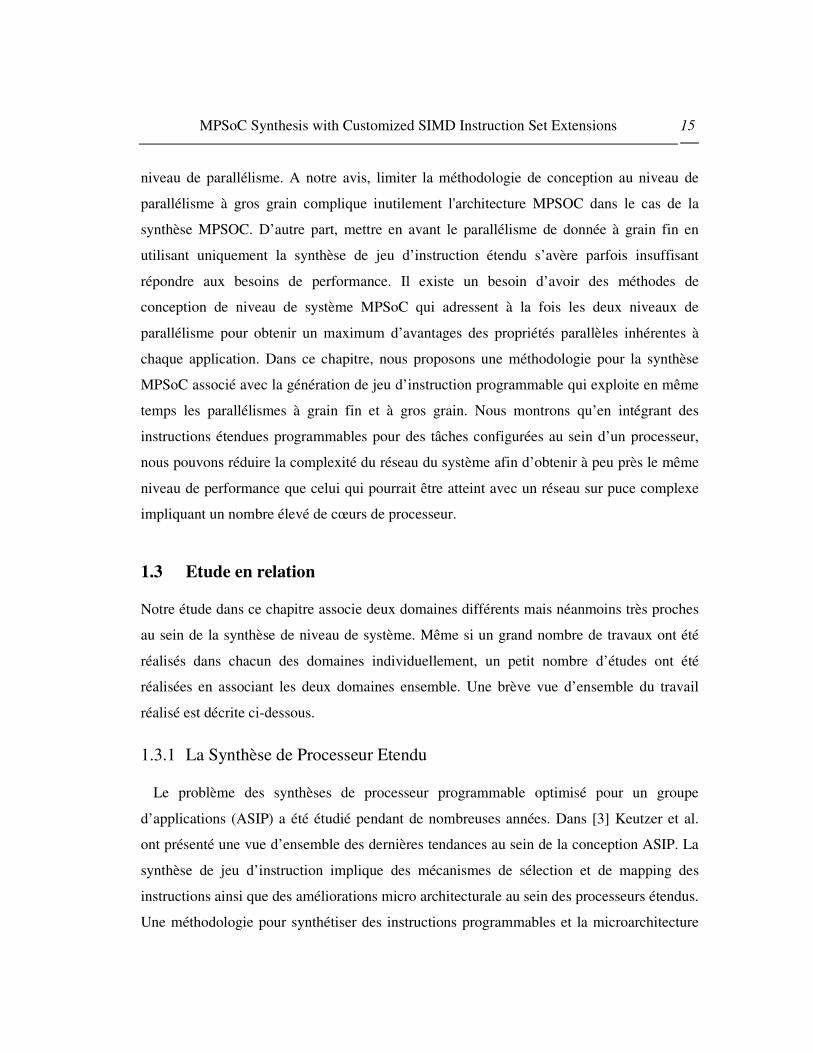
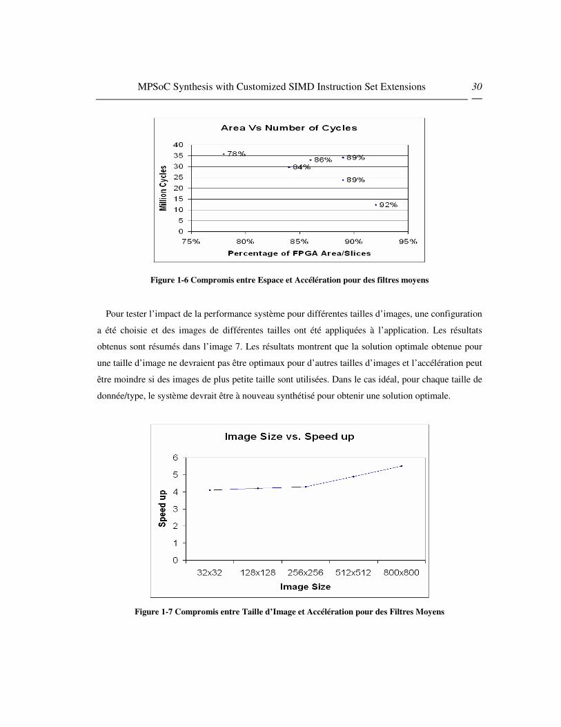
L’image 6 montre un compromise entre l’espace et l’accélération pour une application de
filtre donnée. Nous observons que diverses solutions basées sur les besoins système sont
possibles. Par exemple, si la focalisation se porte sur la vitesse d’exécution, la configuration
5 est la solution adéquate. Si l’espace doit être minimisé, au sein des solutions basées sur
SIMD, la configuration 6 est la meilleure option. Les autres configurations représentent le
compromis entre les deux extrêmes.
MPSoC Synthesis with Customized SIMD Instruction Set Extensions 30
Figure 1-6 Compromis entre Espace et Accélération pour des filtres moyens
Pour tester l’impact de la performance système pour différentes tailles d’images, une configuration
a été choisie et des images de différentes tailles ont été appliquées à l’application. Les résultats
obtenus sont résumés dans l’image 7. Les résultats montrent que la solution optimale obtenue pour
une taille d’image ne devraient pas être optimaux pour d’autres tailles d’images et l’accélération peut
être moindre si des images de plus petite taille sont utilisées. Dans le cas idéal, pour chaque taille de
donnée/type, le système devrait être à nouveau synthétisé pour obtenir une solution optimale.
Figure 1-7 Compromis entre Taille d’Image et Accélération pour des Filtres Moyens

MPSoC Synthesis with Customized SIMD Instruction Set Extensions 31
Cela ne coûte rien de dire que généralement plus d’accélérations ont été observées pour de grandes
tailles de donnée, ce qui prouve l’adaptabilité de SIMD pour des applications ayant un grand nombre
de données.
1.7 Le Flux de Conception de la Méthode de Synthèse MPSoC proposée
Dans cette section, nous décrivons notre méthodologie relative aux synthèses de
multiprocesseurs d’applications spécifiques hétérogènes avec des extensions SIMD
programmables. Le flux de conception est montré dans l’image 8. Notre processus de
conception commence avec le développement de l’application. Pour chaque application, ou
le graphique de tâches peut être extrait par profilement ou alternativement une application
peut être développée comme une chaîne de différentes tâches dans laquelle chaque tâche
représente un opérateur spécifique de différente taille. Nous avons effectué nos expériences
sur des applications de traitement d’images, donc nos tâches représentent un opérateur de
traitement d’images et la totalité de l’application peut être vu telle une chaîne d’opérateurs
de traitement d’images. Dans cette chaîne de traitement d’images, chaque opérateur de
traitement d’images représente un certain nœud d’entrée et de sortie d’images alors que la
communication entre opérateurs est représentée par des bords entre les nœuds. Le problème
des synthèses MPSoC avec des extensions de jeu d’instruction programmables peut être vue
comme une association et une programmation de tâches sur une plateforme de
multiprocesseur tel que :
1. Le temps global d’exécution pour l’application est réduit et les contraintes de
performance sont rencontrées.
2. Chaque processeur est étendu d’une façon appropriée avec des instructions
programmables selon les tâches à associer pour réduire les coûts d’espace.
3. L’architecture de réseau sur puce est simplifiée en raison des améliorations de
performance au niveau des nœuds individuels résultantes de l’insertion d’instruction
programmable au sein d’un processeur à but général.

MPSoC Synthesis with Customized SIMD Instruction Set Extensions 32
Figure 1-8 Méthodologie de Conception MPSoc pour un Processeur SIMD étendu avec un NoC sous-
jacent
Au-delà du développement de l’application, nous avons aussi conçu une plateforme de
référence au début de l’étape de conception. Le choix d’une Plateforme de référence dépend
de la complexité des applications et des contraintes de performance en temps réel et ceci est

MPSoC Synthesis with Customized SIMD Instruction Set Extensions 33
défini intuitivement par le concepteur de système. Cependant, il convient de noter que notre
algorithme pour les synthèses de multiprocesseur est par nature itératif de sorte que la
plateforme de référence est mise à jour à chaque itération de haut niveau, ce qui garanti des
résultats optimaux même si le concepteur de système choisi une plateforme sous optimale
dans le processus de démarrage et que la sélection d’une mauvaise plateforme de référence
prolonge le processus de synthèse en raison du nombre important d’itérations en jeu.
� Problème de Mapping:
Après le développement de la plateforme de référence, différentes tâches des applications
sont associées sur le réseau. Comme mentionné dans la section précédente, le problème de
mapping affecte deux aspects de la conception système adressée : l’architecture de
processeur étendue et le trafic de réseau. Par exemple, si deux tâches consécutives T1 et T2
ont un nombre important de données à transférer entre elles, la décision de mapping devrait
ou essayer d’associer ces deux tâches sur un même élément de calcul ou associer deux
éléments de calcul qui sont voisins dans le réseau de telle sorte que les données n’aient pas
besoin de traverser l’ensemble du réseau pour atteindre l’élément de traitement requis. De la
même manière, des tâches contenant des instructions similaires devraient être associées sur
un processeur étendu avec des instructions SIMD afin de réduire le coût d’espace
d’implémentation de l’instruction étendue.
Dans notre algorithme, notre plateforme de référence n’inclue pas de processeurs SIMD
étendus, aussi le mapping initial est effectué en premier afin de distribuer effectivement les
tâches sur le MPSoC hétérogène visant à réduire les temps de calcul des éléments de
traitement et les temps de communication du NoC sous-jacent. Une fois le mapping réalisé
pour l’application donnée et la plateforme, des simulations sont réalisées afin d’obtenir des
résultats de performance pour la configuration donnée. D’un autre côté, les résultats de
consommation d’espace et d’énergie sont obtenues par la synthèse de tâches individuelles
utilisant des outils de synthèses comportementales. Nous utilisons l’outil de compilateur
“Celoxica's agility” mais n’importe quel outil de synthèse comportementale ou SystemC
pourrait être utilise afin d’obtenir des estimations d’énergie et d’espace pour la plateforme.

MPSoC Synthesis with Customized SIMD Instruction Set Extensions 34
� Génération de Processeur Etendu de Jeu d’Instruction SIMD Programmable:
Comme mentionnée précédemment, le problème de synthèse de jeu d’instruction induit
deux sous problèmes : la sélection du jeu d’instruction et l’association d’instruction. Nous
simplifions le problème de sélection du jeu d’instruction en prenant l’intégralité du standard
SIMD en tant que jeu d’instruction sélectionné. Par ailleurs, l’association d’instruction est
réalisée par un compilateur qui vectorise chaque tâche automatiquement ou par un
programmeur de logiciel qui écrit manuellement le code vectorisé efficient. Notre idée
principale est de commencer à partir d’une totale implémentation d’unité SIMD connectée
en parallèle au Pipeline principal d’un processeur à but général et ensuite de supprimer le
matériel relié aux instructions qui n’ont pas été utilisées pour les tâches implémentées sur le
processeur. La décision concernant les instructions à supprimer dépend des résultats de
profilement qui donnent un type et une fréquence aux instructions utilisées pour un certain
programme. En conséquence, notre processeur personnalisé comprend uniquement les
instructions dont le programme a besoin pour réduire la consommation d’espace et de
puissance au niveau du processeur étendu. Dans notre flux complet, nous définissons aussi
le concept de classe d’équivalence pour éliminer les instructions de vecteur qui prennent
plus d’espace mais qui ne fournissent pas suffisamment d’accélération à cause de leur faible
fréquence dans le programme. Ces instructions de faible fréquence sont éliminées en les
remplaçant avec un ou plusieurs scalaires ou avec une instruction de vecteur sachant
exécuter la même fonctionnalité. Plus de détails sur la classe d’équivalence et la sélection de
jeu d’instruction est hors sujet dans ce chapitre, mais si les lecteurs sont souhaitent plus
d’informations sur ce sujet, ils peuvent consulter [22] .
� Simplification Réseau:
Notre algorithme d’exploration itératif peut reconfigurer la plateforme de référence après
chaque itération de haut niveau. Si les contraintes de performance ne sont pas satisfaites, des
noeuds complémentaires sont ajoutés dans NoC et le processus de programmation de SIMD
est répété une nouvelle fois pour observer les améliorations de performance. Toutefois, si les

MPSoC Synthesis with Customized SIMD Instruction Set Extensions 35
contraintes de performance sont satisfaites alors l’algorithme essai de réduire la complexité
du réseau en supprimant certains nœuds et en répartissant les fonctionnalités implémentées à
partir de ces nœuds jusqu’aux tâches SIMD implémentées au sein du processeur étendu
Une fois que les contraintes de performances sont satisfaites et que la complexité du
système est suffisamment réduite, la configuration est finalisée et le concepteur peut
procéder au processus d’implémentation du système à des niveaux inférieurs d’abstraction.
1.8 Organisation Expérimentale
Notre organisation expérimentale utilise différents outils pour mettre en place une
plateforme afin de vérifier l’efficacité des flux de conception présentés dans la dernière
section. Nous avons réalisés toutes nos expériences avec des processeurs PowerPC [47]
étendus avec AltiVec[48] basés sur un jeu d’instruction SIMD. AltiVec est un point variable
et la totalité des jeux d’instruction SIMD a été conçue et est la propriété de Apple Computer,
IBM et Motorola (l’alliance AIM), et est implémenté sur les versions de PowerPC incluant
les processeurs G4 de Motorola et G5 d’IBM. AltiVec est une marque commerciale
seulement détenue par Motorola, aussi le système se réfère également aux Velocity Engine
d’Apple [49] et VMX d’IBM. IBM Coreconnect [51] est utilisé en tant qu’architecture de
communication standard, ce qui inclus le Processor Local Bus (PLB), le On-chip Peripheral
Bus (OPB), un bus bridge, deux arbiters, et un Device Control Register (DCR) bus. Pour
l’implémentation NoC, nous utilisons systemC base sur les bibliothèques OCCN développé
par STMicroelectronics pour un chemin rapide de vérification de NoC.
Nous avons implémenté une partie du jeu d’instruction AltiVec sur VHDL en utilisant
les outils Xilinx et sur un tableau ML403[52] qui contient un processeur PowerPC 450 avec
une logique programmable basée sur Virtex-4 FPGA. L’environnement de logiciel intégré
(ISE) 7.1 [53] est utilisé pour synthétiser le système et obtenir les besoins d’espace pour
différentes instructions alors que Embedded Development Kit (EDK) [50] est utilisé pour
modéliser une plateforme, écrire le logiciel et l’exécuter en temps réel. Les résultats
d’espace obtenus par implémentation de toutes les instructions sont emmagasinés dans la

MPSoC Synthesis with Customized SIMD Instruction Set Extensions 36
base de données à utiliser en même temps que l’implémentation du flux de conception de
l’application cible.
Figure 1-9 PowerPC 750 étendu avec un jeu d’Instruction AltiVec
Pour la vérification complète des systèmes impliquant des processeurs étendus avec des
architectures de réseau sur puce, nous avons étendu ppc750sim [54] qui est un simulateur
PowerPC 750 (G3) simulator écrit dans SystemC qui accompli une inexactitude de 10% sur
SPEC CINT 2000 en comparaison avec le réel microprocesseur PowerPC 750.
L’architecture de haut niveau de PowerPC 750 est montrée dans l’Image 9. Il convient de
noter que PowerPC 750 ne contient pas d’extension de jeu d’instruction AltiVec, aussi nous
avons écrit l’extension AltiVec pour le PowerPC, ce qui a représenté approximativement
8000 lignes de code et nous les avons ajouté en parallèle au pipeline principal du processeur
tel que cela est montré par les deux boites les plus à gauche dans l’étape d’Exécution du
pipeline. Même si PowerPC750 utilise l’exécution d’instruction en dehors du pipeline
principal utilisé pour l’exécution d’instruction de but général, notre partie du pipeline qui
démarre après l’unité distribuée (dispatch unit) et qui exécute les instructions, utilise, pour
simplifier, d’une manière ordonnée les instructions SIMD.
MPSoC Synthesis with Customized SIMD Instruction Set Extensions 37
Une fois que la micro-architecture du processeur est étendu avec l’instruction SIMD
programmable, a été créé un fichier top niveau qui peut d’initialiser de multiples copies des
processeurs. En utilisant systemC, des interfaces de réseau ont été écrites et des
bibiothèques de réseau fournies par OCCN [55] ont été utilisées pour implémenter une
architecture de réseau entre les processeurs. Les bibliothèques OCCN fournissent le router,
le packet data unit (PDU), les queues, les canaux, les classes de statistiques et d’autres
éléments de base nécessaire à l’implémentation et à l’analyse d’une architecture de
communication. Dans le cas de l’utilisation des IPs de matériel programmable, nous avons
la description de niveau comportemental de systemC pour écrire les éléments de matériel et
ils ont été synthétisés en utilisant le compilateur Celoxica agility [56] afin d’obtenir un
espace estimatif pour chaque accélérateur matériel. En utilisant tous ces éléments, il devient
possible d’implémenter un système complexe de multiprocesseurs hétérogènes dans un délai
de développement très court. Durant notre expérimentation, nous avons implémenté
manuellement des fichiers top niveau de systemC afin d’initialiser et connecter tous ces
composants pour des configurations variables testées durant notre processus d’exploration
de l’espace de conception. L’image 10 montre le diagramme de bloc d’un réseau sur puce
3x3 basé sur une construction de typologie de maillage utilisant notre environnement
d’expérience. Les queues entre les routeurs et les éléments de calculs ont été montrées en
utilisant des marques sous forme de flèche décrivant la direction des communications alors
que les éléments de calculs sont connectés au réseau au moyen d’interface de réseau. Ces
éléments de calculs peuvent être PowerPC 750, PowerPC 750 de but général étendu avec
des instructions programmables telles que montrées dans l’image 4 ci-dessous ou des IPs de
matériel programmable écrits avec systemC et synthétisé acec le compilateur Agility. Pour
la vectorisation des différentes tâches, nous pouvons utiliser gcc 4.0 [57] ou l’outils de
vectorisation VAST [58]. Toutefois, nous observons que les techniques d’auto-vectorisation
ne fournissent pas de code vectorisé optimal. Donc dans la mesure du possible nous avons
opté pour une vectorisation de code manuelle afin d’avoir de meilleurs résultats. Ceci met en
exergue le fait que tant que les techniques d’auto-vectorisation ne sont pas assez avancées,
les techniques de synthèse de niveau de système impliquant des instructions SIMD ne

MPSoC Synthesis with Customized SIMD Instruction Set Extensions 38
devront pas être effectivement automatisées. Autrement dit, des avancées dans les
techniques de vectorisation au sein des compilateurs seront grandement utiles et donc
réduire le temps pour les synthèses SIMD de niveau de système exploitant des parallélismes
de donnée à grain fin.
Figure 1-10 Un Réseau sur Puce typique modélisé en utilisant notre système.
1.9 Résultats Et Discussion
Nous avons testé notre approche de synthèse MPSoC avec des extensions d’instruction
programmable pour l’application de détecteur d’angle Harris décrit dans l’image. 11(a). Un
détecteur d’angle Harris est fréquemment utilisé par la détection « Point of Interest" (PoI)
dans de nombreuses applications embarquées de temps réel durant la phase de prétraitement
des données pour la détection d’objet de temps réel dans un flot vidéo.

MPSoC Synthesis with Customized SIMD Instruction Set Extensions 39
� Bibliothèque d’Opérateurs de Traitement d’Image :
Nous avons implémenté quelques opérateurs de traitement d’image dans un matériel tel
que des accélérateurs. Ces opérateurs incluent différents filtres communément utilisés, des
détecteurs d’angle, des opérateurs de point et de géométrie. Chaque opérateur est synthétisé
et des estimations d’espace et de performance sont obtenues. Ces performances basées sur
des valeurs de coût sont mises en référence avec des processeurs de but général et des
processeurs étendus d’instruction SIMD afin de comparer les différentes implémentations de
chaque opérateur. Si un opérateur utilisé dans l’application est trouvé dans la bibliothèque, il
est directement utilisé à partir de là sinon le concepteur de matériel doit implémenter
l’opérateur manuellement et le synthétiser pour obtenir des résultats de performance et
d’espace. Pour l’opérateur trouvé dans l’application donnée, le tableau 4 fournit une
comparaison des résultats de performance pour chaque opérateur dans trois différents
implémentations tandis que le tableau 3 fournit les besoins d’espace pour chaque opérateur
Figure 1-11(a) : Image de l’Application en cours Image 1-11(c) Graphique de Tâches mises à jour
de Traitement de Synthèse d’un Modèle de Half Pipeline
Image 1-11(b) Graphique de Tâches pour le modèle SPMD Image 1-11(d) Graphique de Tâches pour
le

MPSoC Synthesis with Customized SIMD Instruction Set Extensions 40
quand ils sont implémentés dans un matériel dédié. On peut voir que les résultats des temps
de calcul des accélérateurs matériel sont meilleurs que ceux des implémentations SIMD
même si on devrait noter que pour permettre l’ajout matériel d’un accélérateur dans une
accélération sur un niveau de système impliquant un NoC, le temps de communication des
deux tâches implémentées sur ces deux différents processeurs devrait également être réduit
pour rendre bénéfique l’effort de conception de matériel dédié. D’un autre côté, même si
l’implémentation SIMD implique un effort de programmation dans le développement
logiciel (si l’option d’auto-vectorisation de donne pas de bon résultat et que le programmeur
opte pour une vectorisation manuelle), il n’y a pas de coûts de communication impliqués
parce que les instructions étendues sont couplées d’une manière proche au processeur à but
général dans lequel les instructions de vecteur et de scalaire voyage simultanément au sein
de leur pipeline respectif.
Table 1-3 Résultats des Synthèses pour une Chaîne de Détecteur Harris Corner
Area ( Computational Logic and
Memory)
Module Name
Comp. Logic
Slices
Memory
(bits)
Critical
Path
(ns)
Synth
Freq.
(MHz)
Sobel 896 131072 14.41 69.39
P2P-Mul 604 262144 11.04 90.33
Gauss 760 131072 6.32 61.1
Harris 1404 294912 19.32 51.76
Table 1-4 Comparaison des Performances des Opérateurs dans les Versions HW, SIMD et GPP
HW (cycles) SIMD (cycles) GPP ( cycles)
Sobel 16676 24612 179670
Mul 3152 5675 41990
Gauss 7966 18641 130490
Harris 13225 9522 66440
Pour notre application, les contraintes de performance étaient données en terme de nombre
d’images traitées en une seconde. Même si nous avons utilisé des blocs d’image de 64x64

MPSoC Synthesis with Customized SIMD Instruction Set Extensions 41
durant nos simulations pour conserver des temps de simulations courts, en nous référant au
valeur de cycle par pixel obtenue avec les résultats de simulation, nous estimons le nombre
d’images 512x512 images traitées en une seconde avec la même puissance de calcul. Notre
objectif était de réduire la complexité du réseau alors que s’achever un traitement de 60
images/seconde dans l’application.
Pour estimer le montant de l’amélioration des performances, nous avons d’abords
exécuté notre application sous un seul PowerPC 750 de but général tournant à 333.33 MHz.
Le processeur n’était pas étendu avec des instructions programmables et aucun autre
élément de calcul n’était utilisé dans l’environnement. Les tailles d’instruction et de data
cache, la largeur du data bus et les paramètres de soft reliés étaient figés afin de rendre
constantes toutes les configurations de processus de conception pour faire des comparaisons
réalistes. Nos résultats de simulation initiaux nous montrent qu’il faut 186.4 de tour de
cycles par pixel pour traiter toute l’opération de la chaîne de traitement d’image. Avec ce
niveau de performance, on peut seulement traiter 6.8 images en une seconde, ce qui
nécessite pour notre application d’énormes améliorations afin de satisfaire les contraintes de
performance.
Table 1-5 Accélération du système de Monoprocesseur étendu SIMD vs. Processeur à But Général
Function SIMD
Version
(Cycles)
64x64
block
SIMD
Version
(Cycles/pixel)
Non-SIMD
version
(Cycles)
64x64
block
Non-SIMD
Version
(Cyc/pxl)
Area Increase for
SIMD Version
(Number of Slices)
Speedup
of Vector
over
Scalar
Version
Sobel 24612 6.01 179670 43.86 1664 7.3
Multiplication 5675 1.39 41990 10.25 271 7.4
Gauss 18641
4.55 130490 31.86 1590 7.0
Harris 9522 2.32 66440 16.22 890 6.9
Total
(Monoprocessor
System)
107082 26.14 763550 186.41 1935 7.1

MPSoC Synthesis with Customized SIMD Instruction Set Extensions 42
Un autre cas pour estimer les améliorations de performance avec des extensions SIMD
programmables a été testé. Dans ce cas, nous avons également utilisé un système de
monoprocesseur, cependant la différence était que le processeur PowerPC était étendu avec
les instructions SIMD programmables utilisées par l’application. Nous avons observé
qu’avec une légère augmentation dans l’espace, nous pouvions obtenir une accélération
significative pour l’architecture le processeur de but général. Les résultats pour chaque tâche
et la totalité de l’accélération sont donnés dans le tableau 5 ci-dessous. Nos résultats ont
montré que l’extension SIMD a fournit grosso modo une accélération sept fois supérieur
nous permettant de traiter 48 images/seconde. Ceci a constitué un progrès significatif pour
les résultats de processeur de base, cependant les besoins de performance n’ont toujours pas
été satisfaits, ce qui nous a demandé d’aller vers les étapes suivantes de notre méthodologie
impliquant un MPSoC avec un NoC sous-jacent.
Tel qu’expliquer dans le flux de conception, nous avons modélisé la plateforme de
référence qui a été choisie pour être un système de multiprocesseurs avec un NoC sous-
jacent de 2x2, avec une typologie de maillage. Cette configuration utilise un processeur de
but général qui n’est étendu avec aucune instruction SIMD alors que trois noeuds sont des
accélérateurs matériel modélisés dans SystemC. Nos résultats ont montré un traitement de
15 images par seconde, ce qui est plus du double qu’avec les résultats de processeur à but
général, mais des améliorations de performance encore plus significative sont toujours
attendues. A cette étape, nous pouvons voir que malgré l’exploitation à un certain degré du
parallélisme à gros grain, comme le parallélisme de donnée à grain fin n’est pas traité
correctement, notre application est toujours très loin de satisfaire les contraintes de
performance. Si notre méthode était basée sur des techniques de synthèse traditionnelles,
nous aurions du avoir besoin d’augmenter la complexité de NoC de 3x3 pour avoir des
améliorations de performance supérieures. Mais, dans notre cas, l’étape suivante
d’exploration a impliqué l’implémentation de tâches scalaires au sein des versions de
vecteur. Les tâches de goulot d’étranglement sont vectorisées et le processeur est étendu en
fonction de la nouvelle instruction ajoutée à la tâche à cause de la vectorisation. Après
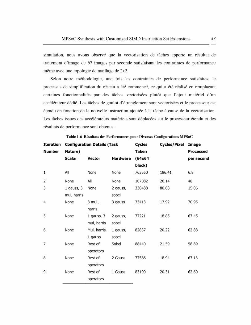
MPSoC Synthesis with Customized SIMD Instruction Set Extensions 43
simulation, nous avons observé que la vectorisation de tâches apporte un résultat de
traitement d’image de 67 images par seconde satisfaisant les contraintes de performance
même avec une topologie de maillage de 2x2.
Selon notre méthodologie, une fois les contraintes de performance satisfaites, le
processus de simplification du réseau a été commencé, ce qui a été réalisé en remplaçant
certaines fonctionnalités par des tâches vectorisées plutôt que l’ajout matériel d’un
accélérateur dédié. Les tâches de goulot d’étranglement sont vectorisées et le processeur est
étendu en fonction de la nouvelle instruction ajoutée à la tâche à cause de la vectorisation.
Les tâches issues des accélérateurs matériels sont déplacées sur le processeur étendu et des
résultats de performance sont obtenus.
Table 1-6 Résultats des Performances pour Diverses Configurations MPSoC
Configuration Details (Task
Nature)
Iteration
Number
Scalar Vector Hardware
Cycles
Taken
(64x64
block)
Cycles/Pixel Image
Processed
per second
1 All None None 763550 186.41 6.8
2 None All None 107082 26.14 48
3 1 gauss, 3
mul, harris
None 2 gauss,
sobel
330488 80.68 15.06
4 None 3 mul ,
harris
3 gauss 73413 17.92 70.95
5 None 1 gauss, 3
mul, harris
2 gauss,
sobel
77221 18.85 67.45
6 None Mul, harris,
1 gauss
1 gauss,
sobel
82837 20.22 62.88
7 None Rest of
operators
Sobel 88440 21.59 58.89
8 None Rest of
operators
2 Gauss 77586 18.94 67.13
9 None Rest of
operators
1 Gauss 83190 20.31 62.60

MPSoC Synthesis with Customized SIMD Instruction Set Extensions 44
Les quatre dernières configurations dans le Tableau 6 montre le processus de réduction
de réseau dans notre méthodologie. Nous avons observé qu’avec un opérateur Gaussien dans
le matériel et le reste des opérateurs déplacés dans le logiciel vectorisé, que nos contraintes
de performance continuaient à être satisfaites, prouvant ainsi le profond impact des
instructions étendues de vecteur sans la synthèse MPSoC. Ceci a demandé un MPSoC basé
sur un processeur de but général étendu avec une instruction SIMD programmable avec
seulement un accélérateur matériel. Il semblerait également qu’avec cette simple
configuration, NoC ne serait plus nécessaire et les routeurs et les interfaces de réseau
peuvent être beaucoup plus simplifiés pour réduire la complexité d’implémentation.
1.10 Conclusions
Dans ce châpitre, nous avons proposé une méthodologie pour synthétiser un MPSoC avec
un NoC sous-jacent concurremment avec des processeurs de jeu d’instruction étendus
comme noeuds MPSoC individuels. Faire les deux synthèses en une seule étape révèle de
nouvelles relations qui existent entre le problème de mapping, l’architecture de processeur et
les paramètres de réseau. Nos résultats expérimentaux prouvent l’efficacité de notre
méthodologie en montrant que l’architecture réseau peut être simplifiée d’une manière
significative en générant des processeurs étendus avec des instructions SIMD
programmables sur des noeuds individuels dans un NoC.
Cette étude fournit un premier aperçu du problème de synthèse MPSoC qui autorise les
concepteurs à exploiter le parallélisme sur deux niveaux différents au sein d’une seule
méthode de synthèse. Cependant, une étude plus approfondie est nécessaire pour divers
aspects du problème. Cette étude devra inclure des synthèses de typologie de NoC
irrégulières avec la génération d’instruction programmable, classifier les applications
appropriées pour la méthodologie, et comprendre les paramètres inter reliés pour MPSoC,
NoC et les problèmes de synthèse d’Extension de jeu d’instruction.
En considérant que la productivité est un souci majeur pour l’industrie, notre

MPSoC Synthesis with Customized SIMD Instruction Set Extensions 45
méthodologie essaye déjà d’adresser des enjeux de productivité en simplifiant le problème
de synthèse et en restreignant le domaine d’application aux applications de donnée intensive
ou DSP. Cependant, le besoin existe toujours d’automatiser le flux de productivité qui
demande des améliorations significatives dans les techniques d’auto-vectorisation et plus
d’automatisme dans le matériel existant et les techniques de synthèse de logiciel.
REFERENCES
[1] International Technology Roadmap for Semiconductors: Design, 2005 [2] "New Degrees of Parallelism in Complex SOCs",MIPS Technologies, Inc. July 2002 [3] K. Keutzer, S. Malik, and A. R. Newton, “From ASIC to ASIP: The next design discontinuity,” in Proc.
Int. Conf. Computer Design, Freiburg, Germany, Sep. 2002, pp. 84–90. [4] J. Huang and A. M. Despain, “Generating instruction sets and microarchitectures from applications,” in
Proc. Int. Conf. Computer-Aided Design, San Jose, CA, Nov. 1994, pp. 391–396. [5] J. van Praet, G. Goossens, D. Lanneer, and H. De Man, “Instruction set definition and instruction set
selection for ASIPs,” in Proc. Int. Symp. High-Level Synthesis, Niagara, ON, Canada, May 1994, pp. 11–16.
[6] R. Leupers and P. Marwedel, “Instruction set extraction from programmable structures,” in Proc. Eur.
Design Automation Conf., Paris, France, Sep. 1994, pp. 156–160. [7] C. Liem, T.May, and P. Paulin, “Instruction-set matching and selection for DSP and ASIP code
generation,” in Proc. Eur. Design Automation Conf., Paris, France, Mar. 1994, pp. 31–37. [8] W. E. Dougherty, D. J. Pursley, and D. E. Thomas, “Subsetting behavioral Intellectual property for low
power ASIP design,” J. VLSI Signal Process., vol. 21, no. 3, pp. 209–218, Jul. 1999. [9] K. Kucukcakar, “An ASIP design methodology for embedded systems,” in Proc. Int. Symp. HW/SW
Codesign, Rome, Italy, May 1999, pp. 17–21. [10] H. Choi, J.-S. Kim, C.-W. Yoon, I.-C. Park, S. H. Hwang, and C.-M. Kyung, “Synthesis of application
specific instructions for embedded DSP software,” IEEE Trans. Comput., vol. 48, no. 6, pp. 603–614, Jun. 1999.
[11] J. E. Lee, K. Choi, and N. Dutt, “Efficient instruction encoding for automatic instruction set design of configurable ASIPs,” in Proc. Int. Conf. Computer-Aided Design, San Jose, CA, Nov. 2002, pp. 649–654.
[12] F. Sun, S. Ravi, A. Raghunathan, and N. K. Jha, “Synthesis of custom processors based on extensible platforms,” in Proc. Int. Conf. Computer-Aided Design, San Jose, CA, Nov. 2002, pp. 641–648.
[13] Fei Sun, Srivaths Ravi, Anand Raghunathan, Niraj K. Jha, “A scalable application-specific processor synthesis methodology”, in Proc. Int. Conf. Computer-Aided Design, San Jose, CA, Nov. 2003, pp. 283–290.
[14] N. Cheung, S. Parameswaran, and J. Henkel, “INSIDE: Instruction selection/identification and design exploration for extensible processors,” in Proc. Int. Conf. Computer-Aided Design, San Jose, CA, Nov. 2003, pp. 291–297.
[15] N. Cheung, S. Parameswaran, J. Henkel, and J. Chan, “MINCE: Matching instructions using combinational equivalence for extensible processors,” in Proc. Design Automation Test Europe Conf., Paris, France, Feb. 2004, pp. 1020–1027.
[16] K. Atasu, L. Pozzi, and P. Ienne, “Automatic application-specific instruction-set extensions under microarchitectural constraints,” in Proc. Design Automation Conf., Anaheim, CA, Jun. 2003, pp. 256–261.
[17] N. Clark, H. Zhong, W. Tang, and S. Mahlke, “Processor acceleration through automated instruction set customization,” in Proc. Int. Symp. Microarchitecture, San Diego, CA, Dec. 2003, pp. 40–47.

MPSoC Synthesis with Customized SIMD Instruction Set Extensions 46
[18] A. Peymandoust, L. Pozzi, P. Ienne, and G. De Micheli, “Automatic instruction-set extension and utilization for embedded processors,” in Proc. Int. Symp. Application-Specific Systems, Architectures, and
Processors, Hague, The Netherlands, Jun. 2003, pp. 108–118. [19] P. Biswas and N. Dutt, “Greedy and heuristic-based algorithm for synthesis of complex instructions in
heterogeneous-connectivity-based DSPs,” School Inf. Comput. Sci., Univ. California, Irvine, Tech. Rep. 03-16, May 2003.
[20] P. Biswas, K. Atasu, V. Choudhary, L. Pozzi, N. Dutt, and P. Ienne, “Introduction of local memory elements in instruction set extensions,” in Proc. Design Automation Conf., San Diego, CA, Jun. 2004, pp. 729–734.
[21] D. Goodwin and D. Petkov, “Automatic generation of application specific processors,” in Proc. Int. Conf.
Compilers, Architecture, and Synthesis Embedded Systems, San Jose, CA, Oct. 2003, pp. 137–147. [22] M. O. Cheema, O. Hammami, "Application-specific SIMD synthesis for reconfigurable architectures",
Special Issue on FPGAs of Microprocessor and Microsystems, Volume 30, Issue 6, Pages 398-412, September 2006
[23] K. K. Ryu, V. J. Mooney III, “Automated Bus Generation for Multiprocessor SoC Design”, DATE 2003 [24] S. Murali, G. De Micheli, “An Application-Specific Design Methodology for STbus Crossbar
Generation”, DATE 2005 [25] "Constraint Driven Bus Matrix Synthesis for MPSoC", Processdings of ASP-DAC 2006, Page 30-35 [26] L. Benini and G. De Micheli, “Networks on chips: a new SoC paradigm,” IEEE Comput., vol. 35, no. 1,
pp. 70–78, Jan. 2002. [27] W. Dally and B. Towles, “Route packets, not wires: On-chip interconnection networks,” in Proc. DAC,
2001, pp. 684–689. [28] A. Hemani et al., “Network on a chip: An architecture for billion transistor era,” in Proc. IEEE NorChip
Conf., 2000, pp. 166–173. [29] A. Jantsch and H. Tenhunen, Eds., Networks-on-Chip. Norwell, MA: Kluwer, 2003. [30] T. Bjerregaard and S. Mahadevan,"A Survey of Research and Practices of Network-on-Chip", ACM
Computing Surveys, Vol. 38, March 2006, Article 1. [31] Umit Y. Ogras, Jingcao Hu, Radu Marculescu, " Key Research Problems in NoC Design: A Holistic
Perspective", Proceedings of the 3rd IEEE/ACM/IFIP international conference on Hardware/software codesign and system synthesis, Jersey City, NJ, USA Pages: 69 - 74 , 2005
[32] S. Kumar et al., “A Network on Chip Architecture and Design Methodology,” Proc. Int’l Symp. VLSI 2002, pp. 105-112, Apr. 2002.
[33] E.B. Van der Tol and E.G.T. Jaspers, “Mapping of MPEG-4 Decoding on a Flexible Architecture Platform,” Proc. SPIE 2002, pp. 1-13, Jan. 2002.
[34] A. Pinto et al., “Efficient Synthesis of Networks on Chip,” Proc. Int’l Conf. Computer Design 2003, pp. 146-150, Oct. 2003.
[35] J. Hu and R. Marculescu, “Energy-Aware Mapping for Tile-Based NOC Architectures under Performance Constraints,” Proc. Asia and South Pacific Design Automation Conf. 2003, pp. 233-239, Jan. 2003.
[36] D. Bertozzi, A. Jalabert, S. Murali, R. Tamhankar, S. Stergiou, L. Benini, Giovanni De Micheli, " NoC Synthesis Flow for Customized Domain Specific Multiprocessor Systems-on-Chip", IEEE Transactions on Parallel and Distributed Systems, Vol16,No; 2, Feb 2005
[37] Kees Goossens, John Dielissen, Om Prakash Gangwal, Santiago Gonz´alez Pestana, Andrei R˘adulescu, and Edwin Rijpkema, "A Design Flow for Application-Specific Networks on Chip with Guaranteed Performance to Accelerate SOC Design and Verification", Proceedings of the Design, Automation and Test in Europe Conference and Exhibition (DATE’05)
[38] A.Pinto et al., “Efficient Synthesis of Networks on Chip”, ICCD 2003, pp. 146- 150, Oct 2003. [39] W.H.Ho, T.M.Pinkston, “A Methodology for Designing Efficient On-Chip Interconnects on Well-
Behaved Communication Patterns”, HPCA 2003, pp. 377- 388, Feb 2003. [40] T. Ahonen et al. ”Topology Optimization for Application Specific Networks on Chip”, Proc. SLIP 04. [41] K. Srinivasan et al., “An automated technique for topology and route generation of application specific on-
chip interconnection networks", Proceedings of ICCAD 2005, 6-10 Nov. 2005 Page(s): 231 – 237

MPSoC Synthesis with Customized SIMD Instruction Set Extensions 47
[42] David Sheldon, Rakesh Kumar, Frank Vahid, Roman Lysecky, and Dean Tullsen. "Application-Specific Customization of Parameterized FPGA Soft-Core Processors". International Conference on Computer-Aided Design, ICCAD, San Jose, November 2006
[43] Rakesh Kumar, Dean Tullsen, and Norman Jouppi. " Core Architecture Optimization for Heterogeneous Chip Multiprocessors". International Conference on Parallel Architectures and Compilation Techniques, PACT, Seattle, April 2006
[44] Automatic Application-Specific Microarchitecture Reconfiguration; by Shobana Padmanabhan, Ron K. Cytron, Roger D. Chamberlain and John W. Lockwood; 13th Reconfigurable Architectures Workshop (RAW), Apr 25-26, 2006
[45] R. Kumar, K. I. Farkas, N. P. Jouppi, P. Ranganathan, and D. M. Tullsen. Single-ISA Heterogeneous Multi-core Architectures: The Potential for Processor Power Reduction. In International Symposium on Microarchitecture, Dec. 2003.
[46] Fei Sun, Srivaths Ravi, Anand Raghunathan, Niraj K. Jha "Application-Specific Heterogeneous Multiprocessor Synthesis Using Extensible Processors", IEEE Transactions on Computer Aided Design of Integrated circuits and systems, Vol 25, No.9, Sep 2006
[47] PowerPC Processor reference Guide-Embedded Development Kit EDK 7.1i-UG 018(v 3.0) August 20, 2004
[48] M. Phillip et al,”AltiVec Technology: Accelerating Media Processing Across the Spectrum”, In HOTCHIPS10, Aug 1998.
[49] Velocity Engine: http://developer.apple.com/hardware/ve/index.html [50] Platform Specification Format Reference Manual- Embedded Development Kit EDK 7.1i-UG 131 (v3.0)
Aug 20, 2004 [51] CoreConnect™ bus architecture, IBM Microelectronics Whitepaper, 1999 [52] ML 40x Evaluation Platform User Guide, UG080 (v2.0) P/N 0402337 February 28, 2005, 2004-2005
Xilinx, Inc. [53] Xilinx ISE 7.1 Synthesis and Verification User Guide 7.1i-UG 131 (v3.0) Aug 20, 2004 [54] PowerPC Simulator: http://microlib.org/projects/ppc750sim/ [55] Coppola, M.Curaba, S.Grammatikakis, M.D.Maruccia, G.Papariello, F. "OCCN: a network-on-chip
modeling and simulation framework", Proceedings of DATE 2004, Vol.3, Page 174-179 [56] Agility : http://www.celoxica.com/products/agility/default.asp [57] Dorit Nicholas, “Autovectorization in GCC”, GCC Developers’ Summit, pp 105-117, 2004 [58] VAST Code Optimizer, Available: http://www.crescentbaysoftware.com/vast_altivec.html
MPSoC Synthesis with Customized SIMD Instruction Set Extensions 48
2. Motivation
Lack of efficient design methodologies is the primary reason for increasing design
productivity gaps. On one hand, design methodologies have been unable to address the
increasing complexity of new multiprocessor on chip architectures and on the other
hand, the rapid advancements in VLSI process technology have made more transistors
available than the ability to meaningfully design them. This design productivity crisis
first reported by Sematech (www.sematech.org) in 1999 [1] has resulted in more
research efforts in system design methodologies apparently giving birth to the
approaches of IP based design and Platform based design. Importance of innovations in
design technology is highlighted by the report of ITRS [2] mentioning that estimated
design cost of the power-efficient system-on-chip (SOC-PE) defined in the System
Drivers chapter is near $20M in 2005, versus around $900M had Design Technology
innovations between 1993 and 2005 not occurred. Moreover, ITRS also predicts the
same trend to continue assuming that 10x design productivity improvements will be
required for the newly designed portion in the next ten years till 2016 in order to keep

MPSoC Synthesis with Customized SIMD Instruction Set Extensions 49
the design effort constant. This will need in newer methodologies based on higher
design abstraction levels. These methodologies should necessarily have more
automation available especially in the domain of design verification. These
methodologies should be able to reuse the existing IP blocks and system components to
address the shrinking time to markets reinforcing the importance of a need of higher
design productivity.
Figure 2-1 Impact of Design Technology on SoC Implementation Cost
On the other hand, use of parallelism inherent in multimedia applications to
optimally design the embedded system has been studied very extensively. Design
methodologies can be divided into two categories based on the parallelizable nature of
the application. Methodologies based on fine grained parallelism involve superscalar,
VLIW, pipelining, Vector and SIMD systems. Instruction set synthesis and ASIP
(Application Specific Instruction set processor) synthesis methodologies address this
type of parallelism. Coarse grained parallelism addresses the issues of multi-tasking,
multithreading and multiprocessing. Methodologies related to MPSoC and NoC

MPSoC Synthesis with Customized SIMD Instruction Set Extensions 50
synthesis target coarse grained parallelism. There are no methodologies that address
both coarse grained and fine grained parallelism at the same time. Major reason for lack
of integrated fine grained and coarse grained methodologies is that each of the sub
problem ( MPSoC Synthesis and ASIP Synthesis) are themselves very complex
problems having large design spaces associated with them and taking both problems as
a single problem intensifies the problem complexity. Design productivity requirements
forbid the use of these methodologies for real world system on chip applications.
In this thesis, we propose a methodology that combines the problem of ASIP
synthesis with MPSoC with an underlying NoC. We use various techniques based on
high level transaction level modeling (TLM), behavioral synthesis and platform based
design to meet the productivity requirements. Focus of our proposed methodology has
been image processing multimedia application. We observe that multimedia application
have significant amount of coarse grained and fine grained data level parallelism at the
same times. Vectorization and SIMD type of instruction can be used to deal with fine
grained parallelism that can be uncovered by data flow graphs typically used in
compiler theory. Task level parallelism can be used by mapping various tasks on
various computational elements in an MPSoC environment. Results show that our
methodology can be effectively used for complex embedded systems design without a
compromise on design productivity and time to market requirement.
2.1 Embedded systems
Broadly speaking, an embedded system can be defined as a “special purpose computer
system designed to perform one or a few dedicated functions”. In contrast, a general
purpose processor can perform a wide variety of tasks due to its flexible instruction set
suitable for general purpose application. In terms of performance, embedded systems
outperform general purpose processors as an embedded system is dedicated to specific
tasks, design engineers can optimize it, reducing the size and cost of the product, or
increasing the reliability and performance. Last couple of decades have witnessed an
explosion in number of embedded systems operating around us and hence changing our

MPSoC Synthesis with Customized SIMD Instruction Set Extensions 51
lifestyle to a truly digital world. Some of the examples of embedded systems include
audio like mp3 players and telephone switches for interactive voice response systems,
avionics, such as inertial guidance systems, flight control hardware/software and other
integrated systems in aircraft and missiles, cellular telephones and telephone switches,
engine controllers and antilock brake controllers for automobiles, home automation
products, such as thermostats, air conditioners, sprinklers, and security monitoring
systems, handheld calculators, household appliances, including microwave ovens,
washing machines, television sets, DVD players and recorders, medical equipment,
personal digital assistant, videogame consoles , computer peripherals such as routers
and printers, industrial controllers for remote machine operation, digital musical
instruments (digital synthesizers and digital pianos) and security applications such as
DVR and video server etc. Each of these embedded applications has unique
requirements depending on the environment they are supposed to run in. Table 2.1
summarizes major embedded applications and their most important design constraints.
To meet the design requirements for embedded systems, a suitable (and/or standardized)
design procedure needs to be adopted; this design procedure is roughly known as a
design methodology. Next sections is dedicated to exploring various design
methodologies and their target applications for traditional embedded systems.
Table 2-1 Design Requirements for Major Embedded Product Groups
Application Crucial Design Requirements
Portable Low Power Consumption (optimize computation/watt) , Competitive time to
market, Cost
Medical Equipment Safety/Durability, High Performance for better imaging and real time
diagnostics
Automotives Ruggedness, Safety, Cost
Defence Applications Cost not an issue, Safety, Function: Mostly on SW to lead on technology
Networking Switching Speed, Large Gate Count, Bandwidth

MPSoC Synthesis with Customized SIMD Instruction Set Extensions 52
2.2 Embedded System Design methodologies
A design methodology is a set of practices, rules and procedures which ensure that
an embedded system is designed according to its specifications meeting the system
design constraints. For example, referring to the table 2-1, a design methodology for
portable consumer electronic devices should be able to:
� Reduce the design times (time to market)
� Restrict the energy consumption for longer battery life
� Restricting costs to keep the product price to be affordable by consumers
Now various techniques can be used to optimize the design process for the above-
mentioned constraints. In the given example, design times can be reduced by
introducing ESL (electronic system level design) techniques, power consumption can be
controlled by design space exploration with a goal to reduce power consumption or
introducing power management features i.e. turning off the clocks when an IP is not
being used etc and cost for the product can be controlled by introducing formal
verification techniques to avoid late stage bugs. Hence a suitable methodology for
portable consumer electronic device development should adopt a set of techniques, tools
and technologies based on system level design and providing automated design space
exploration for power optimization to meet the goals defined by these portable
applications.
2.2.1 A Brief History of Embedded System Design Methodologies
During 1990’s and early 2000, several embedded system level design methodologies
were proposed by researchers in EDA (electronic design automation). These design
methodologies generally divide the whole design task into four main sub tasks:
1. Partitioning: Functionality of whole seem is seen as a set of interacting
computation subtasks.
2. Allocation: To decide that which computational resources are used to implement
system functionality
3. Scheduling: If a specific resource is used to multiple tasks, how to share that
resource to perform the operations.

MPSoC Synthesis with Customized SIMD Instruction Set Extensions 53
4. Mapping: One to one relationship between computational resources and tasks.
It should be noticed however that all above mentioned subtasks are dependent on each
other and there is a fine distinction between each of the tasks. That’s why many
researchers often merge these tasks together or refer to these terms interchangeably.
More information on System Design Methodologies can be found in [3], [4].
Vulcan [4] and CoSyMa [5] were the first system design methodologies proposed in
early 1990s. Target architecture for both methodologies was a processor, memory and a
set of ASIC components. Vulcan was based on the approach starting from whole
system implemented in hardware in the beginning. System refinement steps included
shifting functionality from hardware to software to reduce hardware costs until
performance constraints remained in reasonable limits. Contrary to Vulcan, CoSyMa
approach started from full system being implemented in software and then shifting the
functionality to dedicated hardware until performance constraints were met. Although
both methodologies were very similar, CoSyMa had a slight advantage over Vulcan in a
sense that some of the elements are difficult to be realized in hardware i.e. dynamic data
structures and Vulcan couldn’t deal with the functions involving such structures.
POLIS [7] was proposed for control dominated applications. While Data Flow Graphs
often prove useful for data dominated application, Finite State Machines have proven to
be suitable for control dominated applications. POLIS proposed an approach for
synthesizing control intensive application by introducing codesign finite state machines
(CFSM). POLIS didn’t include HW/SW codesign and left the choice of partitioning on
hardware designer. VCC (virtual component codesign) by cadence is based on POLIS
approach.
SpecC and SystemC based designed methodologies were introduced in the beginning
of this decade. SpecC [8] and SystemC are based on extension of C and allow the
designer to model system at various abstraction layers. System Design starts by
developing a specification model. In second phase, computation architecture is explored
which follow by exploration of communication architecture for the system.
MPSoC Synthesis with Customized SIMD Instruction Set Extensions 54
While design complexity for embedded system started getting out of control, newer
methodologies started focusing on productivity issues. MESCAL [9] project targeted
tools, algorithms and methodologies based on platform based design. Platform based
design consists of two major design decision. First decision involves selecting a suitable
platform based on previous designs and experience in a specific application domain. A
second step involves refining the architecture according to the need of newer application
being developed.
Another set of design methodologies use formal methods. For example, ForSyDe [10]
is based on use of formal methods for system design. In ForSyDe, system functionality
is captured at a higher abstraction layers and then formal transforms are applied step by
step which results in an implementation model optimized for synthesis. These formal
design methodologies have not been adopted by the industry however because of the
fact that formal languages haven’t been able to get the attraction by industrial designers
who are used to working on Verliog, VHDL and C/C++ for modelling purposes.
2.2.2 Architectural Classification of Embedded Systems
Range of solution to evolving embedded application varies widely depending of the
requirements of programmability, performance, energy consumption, product
development times and budget etc. Fig. 2-2 gives a high level view of various
architectural paradigms and their brief comparison. General purpose processors are at
the high flexibility end of the spectrum as their software can be updated without any
difficulty. However general purpose processors (GPP) are only useful for the
applications where performance constraints are not real time and complex computations
are not required. DSPs are specialized processors designed for data intensive
multimedia applications. Just like general purpose processors, their architecture is also
fixed however their instruction set is designed keeping in mind the generalized
requirement of signal processing systems. Although DSP and GPP architectures are
fixed, they can usually be parameterized in a platform: adjusting the cache configuration
and cache size etc. Design methodologies targeting GPP and DSP based architectures
involve only the development of software. DSP or GPP architecture in usually fixed and

MPSoC Synthesis with Customized SIMD Instruction Set Extensions 55
only design task is to develop optimized software for the given processor architecture.
For example, consider the case of data fetching for an image/video processing
application. Easiest way to store data in the memory is to store it linearly based on per
row storage. In that case, consecutive elements in a column are placed at a distance
equal to pitch (or row size) in the physical memory. However many of the applications
require fetching data on a block by block basis: 8x8 block fetch for MPEG2 where there
is a need to fetch 8 elements of eight consecutive rows for an image at the same time. It
must be clear that it will result in a lot of cache misses if data is stored linearly. Wile
architecture of the processor is already fixed and nothing much can be done in
hardware, a DSP application designer might be interested in using loop permutation,
loop fusion, loop distribution, and loop reversal and data tiling techniques to improve
the cache performance.
Figure 2-2 Comparison of Various Architectural Paradigms
On the high performance end of the spectrum are ASICs and physically optimized ICs.
However, once designed, it is not possible to reprogram them. For slight application
changes or even for bug fixes, whole design is needed to be sent to silicon foundry

MPSoC Synthesis with Customized SIMD Instruction Set Extensions 56
resulting in million of dollars in re-spin costs. For the same example of data fetching
given in the previous paragraph, probably a dedicated hardware module for data tiling
can be added to the existing ASIC that is much faster than the software solutions
proposed. However, design times and cost will be too high as compared to the software
solution which requires mere recompilation of new code. State of the art computation
intensive applications are normally ASIC solutions because of their smaller area, less
power consumption and high computation power.
FPGA based solutions try to introduce software like programmability in hardware
however FPGA architecture is not suitable for applications with tight power/area
constraints. Imagine using FPGA’s programmable logic for adding new memory tiling
module, in which case, we will be getting speed compared to hardware solution with a
programmability of software. Area/Energy consumption however will be however much
higher than the ASIC solution.
Application Specific Instruction Set Processors and Multiprocessor System on Chip
Designs offer a compromise between GPP/DSP and ASIC solutions. ASIPs are the
processors having instruction set flexibility. Instruction Set of an ASIP can be
customized and newer instructions can be added to a processor model which results in
improved performance. ASIP solution to the problem of efficient data fetching might be
adding new instruction that can fetch multiple data elements from different places in the
memory. It should be noticed however that newly added instructions might require
changes in data path and ports at the hardware level as well as retargeting the compiler
for efficient compilation of application with new instructions et.
MPSoC, on the other hand, are multiple processors connected to each other on a single
chip. In a traditional MPSoC, individual processors have fixed architectures and
designers are more concerned about interprocessor interactions. For our simple
example, an MPSoC based solution for optimize memory fetch will be to add a
dedicated memory coprocessor that fetches the data in parallel to the main processor
which performs computations on the fetched data. Unlike ASIP based solution, MPSoC
doesn’t require any changes in the architectures of individual processors and there is no
need for compiler retargeting and changing the microarchitecture of individual

MPSoC Synthesis with Customized SIMD Instruction Set Extensions 57
processor. However, compiling software for parallel multiprocessor systems is still an
unsolved problem and most of the work for synchronization, mapping and scheduling
needs to be done manually for an MPSoC. At this point, it should be clear that ASIP and
MPSoC solutions are also programmable and provide a good combination of
performance and flexibility. A detailed introduction to ASIC and MPSoC design is
given in following section.
2.3 Major Issues in ASIP and MPSoC Synthesis
Several ASIPs [13][15][16][17] and MPSoCs [11][12][14] design and synthesis
methodologies have been proposed by academia in recent years. However, these
methodologies have many commonalities among them. In the subsections below, we
explain the generalized flow for existing ASIP and MPSoC Synthesis problem while
detailed flows will be discussed in chapter 3, 4 and 5.
2.3.1 ASIP Design Key Issues and Methodologies
ASIP design problem can be roughly divided into five main steps as shown in Fig2-3
2.3.1.1 Application Analysis
Input to an ASIP design methodology is an application or a set of applications with
input data and a set of design constraints. In application analysis phase, static or
dynamic profiling of application is performed which is stored in a suitable intermediate
format helpful for subsequent steps. Several profiling tools are available in academia
and industry providing a wide variety of application analysis features. Profiling can give
a system designer an in-depth insight into the bottlenecks to be faced in the application.
That might include the ratio between address calculation instruction to actual
computation instructions, data fetch instructions, busy and idle times for sub-blocks,
cache hits and misses and function call graphs etc.

MPSoC Synthesis with Customized SIMD Instruction Set Extensions 58
Figure 2-3 Generalized ASIP Design Flow
2.3.1.2 Architectural Exploration
Application analysis results are input to this design phase. In this step, architectural
exploration is done manually or automatically using a search algorithm and a scheduler
or simulation based performance estimation techniques.
� Design Space Definition
Design constraints defined in first phase form the basis for forming a design space.
Keeping in mind the design constraints, various architectural parameters are chosen and
a range of values to each parameter are assigned. Number of architectural parameters to
be explored and the range of values for each parameter define the size of a design space
to be explored. Embedded system synthesis is a multi-objective optimization problem.
Solution of a search in a design space consists of pareto curves or multidimensional
pareto surfaces depending on the number of design constraints/objectives.

MPSoC Synthesis with Customized SIMD Instruction Set Extensions 59
� Search Algorithms
A suitable algorithm is needed to explore the design space defined in previous stage.
For smaller explorations, exhaustive exploration is recommended but exhaustive search
might requires too much computation power or months and even years of simulation
time to complete. Hence use of greedy/evolutionary algorithm is done to significantly
reduce the exploration times. It is however strongly recommended to make use of
application analysis results which can help a designer understanding the application
characteristic and hence reducing the design space size by eliminating those parameters
which don’t significantly drive the overall performance of the system.
� Performance Estimation
In a design space, each configuration should be tested based on some performance
estimation scheme. Scheduler based performance estimation problem is formulated as
resource constrained scheduling problem where architectural components are chosen as
resources and application is scheduled to generate an estimated cycle count value.
Simulator based performance estimation uses a high level simulator architecture model
to get the application execution times. Recently, direct execution has also been
introduced as simulation based performance estimation techniques prove to be much
slower especially if being done iteratively for design space exploration purposes.
2.3.1.3 Instruction Set Generation
Instruction set generation consists of two inter-related distinct steps.
� Instruction Set Selection
Instruction set election is the phase of selecting a set of candidate instructions for the
ASIP. These instructions can be chosen based on analysis of data flow graphs to verify
the repeatedly occurring instructions and transforming those instructions to faster
specialized instructions. An alternative choice might be detecting the critical code
sections and forming special instructions that can be used to accelerate that critical code.

MPSoC Synthesis with Customized SIMD Instruction Set Extensions 60
� Instruction Matching
Instruction matching requires matching the data flow graph (DFG) of the application
with the pattern of an instruction and updating the DFG by inserting a matching
instruction.
Both of these sub steps require the use of exploration/pattern matching algorithms
which forms another interesting area of research in ASIP and MPSoC synthesis.
2.3.1.4 Code Synthesis
When instruction set is finalized and architecture has been explored, next step is to
synthesize the software code. Either retargetable code generator or compiler generator
are used to achieve this target. Retargetable code generators take application,
instruction set and architecture as input and general the object code. Object code
generation requires instruction mapping, resource allocation and scheduling sub-
problems to be solved. On the other hand, compiler generator takes instruction set and
architecture and a compiler is generated that can generate the object code for the
application written in high level language. A compiler generated in this manner
generally has phases similar to the ones used in general compilers i.e. analysis,
intermediate code generation and optimization.
As it might be clear at this point that ASIP synthesis problem has several aspects and a
lot of research has been done on almost all areas of ASIP synthesis defined above.
While this chapter is dedicated to introducing various aspects of embedded system
design, more technical discussion ob this research work is done in next chapter.
2.3.2 Overview of MPSoC Design Problem
Unlike ASIP design that deals with instruction level details of a program, MPSoC
design is generally related to task/thread level issues of system design. While some of
the research material might be comparing MPSoC performance with ASIP, it should be
noted that both domains of MPSoC design and ASIP design are not competing design
technologies, rather they can be used to complement each other where MPSoC synthesis
considers task level issues and ASIP synthesis considers instruction level details for

MPSoC Synthesis with Customized SIMD Instruction Set Extensions 61
system design process. Similar to ASIP design methodologies, several MPSoC design
methodologies have been proposed. Subsections below discuss various aspects of
MPSoC design and synthesis and how these problems are tackled in general MPSoC
[18][19][20] design methodologies.
Figure 2-4 A Sample MPSoC Architecture
2.3.2.1 Computation Synthesis
Most of the MPSoC design methodologies partition the MPSoC synthesis problem in
two main parts: synthesis of computation architecture and communication architecture.
A truly heterogeneous MPSoC can have a wide variety of computation elements varying
for general purpose embedded processors to dedicated hardware IPs, customized
processor to dynamically reconfigurable programmable logic.
Computation architecture synthesis problem addresses the issues of:
� Partitioning the application in hardware and software
� Selecting a suitable set of computational elements for various application tasks.

MPSoC Synthesis with Customized SIMD Instruction Set Extensions 62
� Mapping of tasks over computational elements.
� Scheduling the tasks if one or more functionalities are implemented on a single
element.
2.3.2.2 Communication Synthesis
With increasing number of cores in an MPSoC, communication architecture in an
MPSoC is becoming more complex. While basic systems used to have point to point
and bus based communication, more complex architectures are evolving for modern
embedded systems. Bus based crossbars and especially network on chip architectures
have been viewed as the necessary elements of future MPSoC systems. Network on
Chip architectures themselves can be classified into two major classes. Regular NoC
architectures are the ones having a regular structure i.e. Mesh, Torus and Hypercube etc.
Irregular NoC are more suitable for application specific MPSoC design in terms of
performance, area and energy consumption. Fig2.5 summarizes various communication
architectures.
Figure 2-5 Classification of Communication Architectures
MPSoC Synthesis with Customized SIMD Instruction Set Extensions 63
2.3.2.3 Design Space Exploration
In terms of design options, there are several parameters in both communication and
computation architectures for MPSoC design. Individual components in NoC and
MPSoC themselves have many configuration parameters attached to them. Hence
design space attached to MPSoC design is even larger as compared to monoprocessor
systems. However design space exploration algorithms used in ASIP and MPSoC
synthesis are same which are often originating from multi-objective optimization
problem solving techniques.
2.3.2.4 Design Reuse: IP and Platform Based Design
With increasing size of embedded systems, productivity has become a serious issue and
“bottom up” design approaches which start system development from scratch have
become useless. To cope with this issue, IP based design approaches were introduced in
90’s. However IP reuse has become insufficient for modern MPSoC system and
platform based designs have evolved. Concept behind platform based design is to use a
pre-developed platform for a general category of applications and to customize it
according to newer applications.
2.4 Organization of the Thesis:
Rest of the thesis is organized as follows: Chapter 3 introduces monoprocessor
ASIP synthesis design methodologies. In this chapter, we discuss the existing
methodologies for ASIP design and application specific instruction set synthesis. For
multimedia applications, we present a case study showing that each of the multimedia
application used only a specific part of complete SIMD instruction sets. To keep area
and energy constraints under control, it is beneficial to customize the SIMD units. Then
we propose our methodology for customized SIMD unit synthesis. SIMD customization
can be considered as a simplified form of ASIP synthesis problem where instruction set
selection is done by choosing the whole SIMD standard which usually evolves through
a lot of industrial experience with multimedia applications. Issue of instruction
matching is resolved by declaring equivalent classes that represents one vector
instruction being equivalent to one of more vector or scalar instructions. Modern

MPSoC Synthesis with Customized SIMD Instruction Set Extensions 64
compilers have started supporting vectorization features. So the job of instruction
matching can also be performed by vectorizing compilers. Availability of existing tools,
well established SIMD standards and compilers results in better productivity than the
traditional ASIP design approaches.
Chapter four introduces system level design methodologies based on higher level
modeling and synthesis. We present a case study based on the use to behavioral tools for
early power estimation. Then we present a methodology that used platform based design
and transaction level modeling techniques together with image processing chain
development for software development and behavioral synthesis for hardware
realization. All these techniques are aimed at resolving the design productivity issues.
We present a case study of embedded application development of intelligent vehicle
systems which shows the effectiveness of our approach. Possible future extensions have
been discussed in terms of ACCORD/UML based design approaches to be used with
SystemC based designs at the end of this chapter.
Chapter five combines the work done in chapter three and four to come up with
an integrated customized SIMD design methodology based on MPSoC with an
underlying NoC. This chapter introduces the issues coming into picture when two
problems are combined together in a single problem. We observe that mapping problem
in MPSoC design in closely coupled by customized SIMD generation so SIMD
generation and mapping can't be done in two distinct steps. Rather they should be part
of a single design flow where effects of SIMD generation can be studied on task
mapping in the MPSoC and vice versa. We propose a design flow addressing the issue
and show that a NoC can be significantly simplified if SIMD units in the system are
customized efficiently resulting is lower area/energy requirements for the whole system.
This dissertation concludes by summarizing contributions, highlighting remaining
shortcomings and discussing promising avenues for future research (Chapter 6).

MPSoC Synthesis with Customized SIMD Instruction Set Extensions 65
References:
[2.1] www.sematech.org [2.2] International Technology Roadmap for Semiconductors: Design, 2005 [2.3] R. Ernst. Codesign of embedded systems: Status and trends. IEEE Design & Test of Computers, 15(2):45–54,
April–June 1998. [2.4] G. D. Micheli and R. K. Gupta. Hardware/software co-design. Proceedings of the IEEE, 85(3):349–365, March
1997. [2.5] R. K. Gupta. Co-Synthesis of Hardware and Software for Digital Embedded Systems. Kluwer Academic
Publishers, 1995. [2.6] R. Ernst, J. Henkel, and T. Brenner. Hardware-software cosynthesis from microcontrollers. IEEE Design & Test
of Computers, 10(4):64–75, December 1993. [2.7] F. Balarin, M. Chiodo, P. Giusti, H. Hsieh, A. Jurescka, L. Lavagno, C. Passerone, A. Sangiovanni-Vincentelli,
E. Sentovich, K. Suzuki, and B. Tabbara. Hardware-Software Co-Design of Embedded Systems: The Polis Approach. Kluwer Academic Publishers, 1997.
[2.8] D. D. Gajski, J. Zhu, R. D¨omer, A. Gerstlauer, and S. Zhao. Spec C: Specification Language and Methodology. Kluwer Academic Publishers, 2000.
[2.9] A. Mihal, C. Kulkarni, M. Moskewicz, M. tsai, N. Shah, S. Weber, Y. Jin, K. Keutzer, C. Sauer, K. Vissers, and S. Malik. Developing architectural platforms: A disciplined approach. IEEE Design & Test of Computers, 19(6):6–16, November-December 2002.
[2.10] Sander, I.; Jantsch, A., “System modeling and transformational design refinement in ForSyDe [formal system design]”, Computer-Aided Design of Integrated Circuits and Systems, IEEE Transactions on Volume 23, Page(s): 17 – 32 Issue 1, Jan. 2004
[2.11] Ahmed Jerraya and Wayne Wolf (editors), Multiprocessor Systems-on-Chip, Elsevier Morgan Kaufmann, San Francisco, California, 2005.
[2.12] Chris Rowen and Steve Leibson. Engineering the Complex SOC. Prentice-Hall PTR, 2004. [2.13] Steve Leibson and James Kim. “Configurable processors: a new era in chip design”. IEEE Computer, July,
2005, pp. 51-59. [2.14] Richard Goering, “Multicore design strives for balance... but programming, debug tools complicate adoption”,
Electronics Engineering Times, March 27, 2006. [2.15] Matthias Gries and Kurt Keutzer (editors). Building ASIPs: The MESCAL Methodology. Springer, 2005. [2.16] Makiko Itoh, Shigeaki Higaki, Yoshinori Takeuchi, Akira Kitajima, Masaharu Imai, Jun Sato, and Akichika
Shiomi, “PEAS-III: An ASIP Design Environment”, ICCD 2000, pp. 430-436. [2.17] Grant Martin, “ESL Requirements for Configurable Processor based Embedded System Design”, IP-SoC
2005, Grenoble, France, pp. 15-20. [2.18] Frank Ghenassia (editor), Transaction-Level Modeling with SystemC: TLM Concepts and Applications for
Embedded Systems, Springer, 2005. [2.19] P. van der Wolf, et. al., “Design and programming of embedded multiprocessors: an interface-centric
approach”, CODES+ISSS 2004, pp. 206-217. [2.20] Pierre Paulin, et. al., “Application of a multi-processor SoC platform to high-speed packet forwarding”, DATE
2004, Volume 3, pp. 58-63.

MPSoC Synthesis with Customized SIMD Instruction Set Extensions 66
3. Embedded Processor Customization
A variety of multimedia processing algorithms are used in media processing
environments for capturing, manipulating, storing, and transmitting multimedia objects
such as text, handwritten data, 2D/3D graphics, and audio objects. Multimedia standards
such as MPEG-1, MPEG-2, MPEG-4, MPEG-7, JPEG2000, and H.264 put challenges
on both hardware architectures and software algorithms for executing different
multimedia processing jobs in real-time. To meet the high computational requirements
of emerging media applications, current systems use a combination of general-purpose
processors accelerated with DSP (or media) processors and ASICs performing
specialized computations. While, benefits offered by general-purpose processors in
terms of ease of programming, higher performance growth, easier upgrade paths
between generations, and cost considerations argue for increasing use of specialized
processors built around general purpose processor architectures [1]. The most visible
evidence of this trend has been the SIMD-style media instruction-set architecture (ISA)
extensions announced for most high-performance general purpose processors (e.g.,
AMD’s 3DNow! [2], Motorola’s AltiVec [3], Intel’s SSE1/SSE2 [4], Sun’s VIS, HP’s

MPSoC Synthesis with Customized SIMD Instruction Set Extensions 67
MAX, Compaq’s MVI and MIP’s MDMX). Research work done over the study of area
constraints of SIMD shows that implementation of whole SIMD units is very expensive
in terms of area and energy requirements [5], [6] which makes is unsuitable for
embedded systems with tight area and energy consumption constraints. One of our own
implementation of vector integer instructions of AltiVec SIMD units took almost five
times more area available on Virtex-4 FX12 [7] chip over Xilinx ML403 [8] FPGA
which is roughly equivalent to 90 percent area of a Virtex-4 FX60 FPGA pointing out to
the trend of area cost of AltiVec unit based SIMD implementation. On the other hand,
research also indicates that multimedia applications don’t use all the components of an
SIMD unit and hence implementation of many parts of SIMD units can be avoided to
save area and energy without affecting the speed. As a result, synthesis of customized
SIMD units to optimize the system resources is suggested.
One of the central problems with alternative traditional ASIP approaches is the
hardware design and software migration time/costs. For example, each new ASIP must
be verified both from the functionality and timing perspectives. Additionally, a new
mask set must be created to fabricate the chip. On the software side, the compiler must
be retargeted to each new processor and any hand-written libraries must be migrated to
the new platform. Automation of some of these tasks may be possible but majority of
the work is a manual process. All of these problems make it difficult to adopt a new
ASIP despite of potential advantages. In this chapter, we address these problems by
proposing an “easy to automate” methodology for the application specific synthesis of
SIMD units for digital signal processing applications. Given an application program
written in C or Assembly language and a set of application data, our methodology
synthesizes an RTL description of an SIMD based coprocessor and the extended
instruction set along with the modified assembly language program capable of running
over synthesized system. As a case study, we experimented over PowerPC architecture
based AltiVec units and the results obtained indicate the effectiveness of our
methodology. These results testify to the high potential of the SIMD computation
paradigm in the synthesis of high performance and low-power application specific
hardware architectures.

MPSoC Synthesis with Customized SIMD Instruction Set Extensions 68
3.1 Related Work
Customized SIMD instruction set synthesis can be broadly categorized as a subset of
more generalized "instruction set extension"(ISE) synthesis problem while instruction
set synthesis problem comes under the broader "instruction set architecture" (ISA)
design. In the below paragraphs, we introduce the basics of ISA design and ISE
synthesis problem followed by recent work done in these domains.
� Instruction Set Architecture
An instruction set can be defined as a list of all instructions, and all their variations,
that a processor can execute. For traditional general purpose processors, these
instructions include arithmetic such as add and subtract, logic instructions such as and,
or, and not , data instructions such as move, input, output, load, and store and control
flow instructions such as goto, if ... goto, call, and return. An instruction set, or
instruction set architecture (ISA), is the part of the computer architecture related to
programming, including the native data types, instructions, registers, addressing modes,
memory architecture, interrupt and exception handling, and external I/O. An ISA
includes a specification of the set of opcodes (machine language), the native commands
implemented by a particular CPU design. Instruction set architecture is distinguished
from the microarchitecture, which is the set of processor design techniques used to
implement the instruction set. Computers with different microarchitectures can share a
common instruction set. For example, the Intel Pentium and the AMD Athlon
implement nearly identical versions of the x86 instruction set, but have radically
different internal designs.
Adoption of CISC and RISC based instruction architectures, pipelining and
superscalar computing has been a topic of hot debate during the early days of instruction
set design. However with the evolution in processor design, multimedia applications
and application specific computing, focus of research has moved more towards
instruction set extensions for application specific design. A clear benefit of extending an
existing instruction set with custom instructions is that for each application, a designer

MPSoC Synthesis with Customized SIMD Instruction Set Extensions 69
doesn't need to design the full architecture from scratch rather he needs to concentrate
only on those aspects of system design that are absolutely required for improving
system performance. That's why there has been no significant research since last decade
and most of the work has been either done on standard multimedia VLIW/SIMD
extensions of application specific instruction set extensions for ASIP design.
� Instruction Set Extension
Extending the instruction sets to improve the computational efficiency of applications
is a well studied field. Loosely stated, the problem of identifying ISEs consists of
detecting clusters of operations, which, when implemented as a single complex
instruction, maximizes some metric—typically performance. Such clusters must
invariably satisfy some constraint; for instance, they must produce a single result or use
no more than four input values. ISE synthesis process can roughly be divided into
pattern selection and pattern matching. Pattern selection is the process of selecting an
"instruction superset" while pattern matching is the process of matching instruction
from the selected instruction repository to the patterns in data flow graph of the
application. Several approaches have been proposed for instruction selection and
matching [9] [10] [11]. A good overview of the benefits and challenges involved in
ASIP design is contained in [12]. Early works on architectural synthesis for ASIPs are
contained in [13] and [14]. An approach that generates new logic capabilities for a
processor dynamically has been developed for adaptive machine architecture in [15].
The work in [16] places ASIP synthesis in the context of hardware-software
cosynthesis. It argues that, since the customized instructions added to an existing
instruction set are implemented in hardware, whereas the original instructions are run on
the basic processor core, ASIP synthesis is a variant of hardware-software partitioning.
In [17], an ASIP design system called PEAS-III for synthesizing simple pipelined
ASIPs is described. The work in [18] deals with the selection of intellectual property
surrounding an ASIP core to accelerate application programs. A method to design
parallel and scalable ASIP architectures, suitable for reactive systems, is presented in
MPSoC Synthesis with Customized SIMD Instruction Set Extensions 70
[19]. The work in [20] deals with mapping hardware-software systems specified with
State chart models to an ASIP architecture based on field-programmable gate arrays. In
[46], an early design space exploration methodology is given for clustered very long
instruction word (VLIW) data paths in the context of specific target applications.
Automatic architectural synthesis of VLIW processors is targeted in [47]. Design of
area-efficient hardware blocks of an ASIP are tackled in [48] and [49]. The three
interdependent tasks of microarchitecture design, instruction set design, and instruction
set mapping for a given application are tackled in [50]. In [51], an ASIP design
methodology is given for customizing an existing processor instruction set and
architecture, rather than creating an entirely new processor from scratch.
Each of these algorithms provided in [21]-[26] provides exact formulation or heuristic
to effectively identify those portions of the application’s data flow graph (DFG) that can
be efficiently implemented in hardware. Goodwin [21] searches all possibilities
connected in a dataflow graph when generating fused instructions". In order to avoid
intractability, the search is subject to restrictions that each op-code can have at most two
inputs, one output, and the resultant op-code takes only one cycle to execute. As a
drawback of this approach, it has been observed that using very strict restrictions, such
as these, generally produces poor results. This technique also explores the option of
adding vector operations exposed through loop unrolling. The algorithm proposed in
[26] searches a full binary tree, where each step decides whether or not to include a
node of the DFG into a candidate. Ways to prune the tree are proposed, helping avoid
the worst case O ( N2 ) runtime, but the size of the DFG must still be relatively
constrained in order for the algorithm to complete in a timely manner. This limits its
usefulness for very large basic blocks or in the presence of optimizations that create
large basic blocks, such as loop unrolling. Brisk in [25] proposed an instruction set
methodology for reconfigurable system on Chip designs in which they begin with a set
of customized instructions, which are modeled as directed acyclic graphs (DAGs), not
general graphs. By allowing the instructions to share hardware resources unlike in
traditional silicon compilers, they showed impressive gains in terms of area
requirements.
MPSoC Synthesis with Customized SIMD Instruction Set Extensions 71
While ASIP synthesis can be considered a generalized SIMD synthesis problem, a
very few methodologies to synthesize SIMD units in particular have been proposed [27]
[28]. [27] uses the optimization of Control Data Flow Graphs (CDFG) of the application
code for extraction of SIMD instructions. We observe that for customized SIMD
synthesis, traditional approaches based on DFGs are not efficient enough as SIMD
pattern recognition through CDFG doesn’t completely exploit the possible parallelism
of a program hence speedup because of SIMD usage remains very limited. [28] uses
step by step SIMD instruction decomposition for a manually vectorized program to get
an area efficient processor core, but it doesn’t take into account the standard SIMD
based systems with complex architectures hence it doesn’t represent a real world
scenario of a DSP application using SIMD instructions. That’s why we have
implemented standard AltiVec unit being used as a coprocessor with a PowerPC-405
processor to keep in mind the practical aspects of SIMD while proving the concept
behind our work. There are also some commercial tools available for synthesis of
extensible processors. Commercial examples of extensible processors include HP
Laboratory and STMicroelectronics' Lx [29], Altera's NIOS [30] and Tensilica's Xtensa
[31]. In Altera’s NIOS architecture, extensible instruction set is obtained by introducing
the instructions in the already existing pipeline of the processor which increases the
critical path length of the processor. Just like Xtensa, our methodology emphasizes on
the use of coprocessor that extends the existing instruction set with one more advantage
that we are using well known Instruction Set Architecture (ISA) based on PowerPC
architecture.
3.2 Study of Utilization of AltiVec Units
3.2.1 An Overview of AltiVec
AltiVec is a floating point and integer SIMD instruction set designed and owned by
Apple Computer, IBM and Motorola (the AIM alliance), and implemented on versions
of the PowerPC including Motorola's G4 and IBM's G5 processors. AltiVec is a
trademark owned solely by Motorola, so the system is also referred to as Velocity
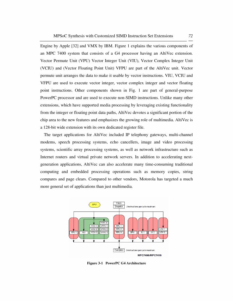
MPSoC Synthesis with Customized SIMD Instruction Set Extensions 72
Engine by Apple [32] and VMX by IBM. Figure 1 explains the various components of
an MPC 7400 system that consists of a G4 processor having an AltiVec extension.
Vector Permute Unit (VPU) Vector Integer Unit (VIU), Vector Complex Integer Unit
(VCIU) and (Vector Floating Point Unit) VFPU are part of the AltiVec unit. Vector
permute unit arranges the data to make it usable by vector instructions. VIU, VCIU and
VFPU are used to execute vector integer, vector complex integer and vector floating
point instructions. Other components shown in Fig. 1 are part of general-purpose
PowerPC processor and are used to execute non-SIMD instructions. Unlike many other
extensions, which have supported media processing by leveraging existing functionality
from the integer or floating point data paths, AltiVec devotes a significant portion of the
chip area to the new features and emphasizes the growing role of multimedia. AltiVec is
a 128-bit wide extension with its own dedicated register file.
The target applications for AltiVec included IP telephony gateways, multi-channel
modems, speech processing systems, echo cancellers, image and video processing
systems, scientific array processing systems, as well as network infrastructure such as
Internet routers and virtual private network servers. In addition to accelerating next-
generation applications, AltiVec can also accelerate many time-consuming traditional
computing and embedded processing operations such as memory copies, string
compares and page clears. Compared to other vendors, Motorola has targeted a much
more general set of applications than just multimedia.
Figure 3-1 PowerPC G4 Architecture

MPSoC Synthesis with Customized SIMD Instruction Set Extensions 73
This makes its instruction set containing more instruction with a generalized
implementation. AltiVec also requires 32 registers of 128 bit width in its
implementation as compared to only 8 registers of same width in SSE, SSE2 and SSE3.
A more generalized implementation of instructions, a larger instruction set and a larger
number of registers require more silicon area as is the case with AltiVec. Less number
of registers in multimedia standards results in difficulties in dealing with the register
allocation problem i.e. spill code, register shadowing etc.
Top level standard implementation of AltiVec has been shown in the Fig. 2. Fig 2
shows that AltiVec instructions can access four registers at a time while three are used
as input to the instruction and fourth can be used to store the results. Vector Register
File consists of 32 registers each of 128 bit length each. Vector unit contains the
implementation of all vector instructions. AltiVec instructions operate on various sizes
of data. Each one 128 bit register can accommodate 16 bytes, 8 half words or four
words hence 16, 8 and 4 operations can be performed in parallel. There are a few
instruction supporting bit wise operations as well making it possible to treat 128 bit of
data at once in a single instructions. A brief introduction to AltiVec instructions with the
perspective of a hardware designer is given below. All the instructions mentioned below
are described in ASM notation as it is easier to understand for hardware designers’.
However for software/algorithm designers, a list of equivalents of ASM and altiVec
intrinsic functions is given in altiVec instruction cross-reference guide [52].

MPSoC Synthesis with Customized SIMD Instruction Set Extensions 74
Figure 3-2 AltiVec Architecture: A System Level View
3.2.2 Vector Integer Instructions
All of the multimedia extensions support integer operations, although the types and
widths of available operations vary greatly. AltiVec supports 8, 16 and 32 bit modulo
and saturation integer arithmetic operations. This comprehensive support is not found in
any other multimedia standard. In traditional integer operations, overflow is dealt with
the modulo as exceeding the maximum or minimum representable range leads to a
result in which only the lower N-bits of the intermediate result are retained and placed
in an N-bit wide result register. This behavior is undesirable in many multimedia
applications, where a better approach is to saturate positive overflow to the largest
representable value or negative overflow to the largest negative value. This is because
we are operating on media (often visual) data types so we would like to be able to add
two values and have the result not be obviously erroneous to our senses; for audio, for
example, clipping is clearly preferable to wrap-around. On the contrary it is obvious that

MPSoC Synthesis with Customized SIMD Instruction Set Extensions 75
modulo operations are easier to implement and to implement the saturate functionality,
there needs to be more logic added (i.e. an “if” statement telling if result overflows, it
should be kept at the maximum value) resulting in more area and energy requirements.
Another added cost of saturation is that unlike the modulo addition of 2’s complement
numbers, saturation requires separate operations for signed and unsigned values which
are also part of AltiVec arithmetic instruction set only among the media standards.
AltiVec supports add, subtract min/max and average among the arithmetic functions.
In the case of multiplication, the length of the result of a multiplication operation is
greater than the length of its operands. On SIMD architecture, a register typically
contains the greatest number of packed values that will fit for a given precision.
Because of this, it is necessary to deal with this expansion property of multiplication in
some way which maps well to SIMD architecture. The instruction sets in traditional
multimedia systems deal it in several ways. Reduction sums result vector sub-elements
to produce fewer result values, and is useful because it is essentially a multiply-add; the
core operation in digital signal processing. While SSE adopted reduction techniques,
AltiVec takes a different approach to deal with the multiplication result width problem.
It supports selectively multiplying either the even or odd elements of the source
registers such that the full width results fit in the destination register. This does put a
small extra burden on the programmer to take the unconventional result ordering into
account (only even or odd elements in a given result register). On AltiVec, this is easily
undone with a mix or data shuffle operation as soon as both even and odd results have
been computed. Truncation predefines a set number of result bits to be thrown away.
This primarily has application then multiplying n-bit fixed point values with fractional
components which together take up a total of n-bits of precision. Pre-scaling of one or
both of the operands may be needed to meet this criterion. AltiVec supports truncating
multiply, rounded truncating multiply for 16 bit signed number while full multiply for 8
and 16 bit unsigned numbers. Another technique for multiplication that is not exploited
by AltiVec is to use the higher precision result registers i.e. 192 bit registers to store the
results to keep the uniformity among the registers.
AltiVec also implements a bit more complex operation often used in digital signal

MPSoC Synthesis with Customized SIMD Instruction Set Extensions 76
processing applications. Fig. 3 shows AltiVec multiply-add operation is shown in the
diagram that perform a multiply low operation and then performs unsigned half word
modulo operation putting the resultant in vD register. An important thing to note is that
AltiVec does have the registers to store the intermediate solutions which are not
accessible by the software developer. For example, in vmladduhm instruction shown
below, Prod and Temp are intermediate registers. This registers are not visible to
software developer and he can’t assign any values to these registers.
Figure 3-3 vmladduhm: Multiply-Add of Eight Integer Elements (16-Bit)
3.2.3 Vector Shift and Rotate Instructions
It is a widely known optimization shortcut in binary arithmetic that a multiplication by
an integer number N, which is a power of two, can be accomplished by a left shift of the
other operand by 2log N bits. Division by the same class of integers can be performed in
the same way, except that a right shift is used. This substitution is often a performance
gain because a shift operation typically has a much lower latency than multiplication.
Shifts are also needed for proper data alignment at the bit level of granularity, as
opposed to the byte or higher level granularity most communication operations work
with. AltiVec provides a comprehensive set of 8, 16 and 32 bit logical shift right,
arithmetic shift right and shift left instructions. Scalar shift instructions are often
implemented as barrel shifters. A barrel shifter is a combinational logic device/circuit
that can "shift or rotate a data word by any number of bits in a single operation.
Basically, a barrel shifter works to shift data by incremental stages which avoids extra
clocks to the register and reduces the time spent shifting or rotating data (the specified
number of bits are moved/shifted/rotated the desired number of bit positions in a single

MPSoC Synthesis with Customized SIMD Instruction Set Extensions 77
clock cycle). Contrary to scalar shift instruction, shift instructions in AltiVec have more
functionality than just a barrel shifter. They require that every block in the vector should
be shifted by a different value mentioned in another vector register. This results in a
need of a generalized shift instruction implementation. Implementing such a generalized
instruction needs more logic resulting in increase area and energy requirements. A Shift
instruction in AltiVec standard has been shown in the Fig. 4.
Figure 3-4 AltiVec Shift Instruction
3.2.4 Vector Permutation and Formatting Instructions
AltiVec instructions perform the same operation on multiple data elements. Because
all the data within a register must be treated identically, instructions with the ability to
efficiently rearrange data bytes within and between registers are crucial to efficiently
utilize AltiVec instruction set. This fact results in the need of various type of data
communication type of instructions like pack/unpack, merge, permute and rotate
instructions. We have observed that these instructions are the most expensive part of
AltiVec in terms of area and energy requirements. These instructions have specifically
been designed for performing classical multimedia operations. For an example, vmrghh
and vmrglh (vector merge low and vector merge high) were specifically defined to deal
with matrix transpose and similar operations. For example, a Matrix Transpose
implementation for 8x8 matrix of 16 bit elements developed by Brett Olsson from IBM
requires only these two instructions [33].
Vmrglh is shown in Fig. 5 while the only difference between vmrghh and vmrlh is that

MPSoC Synthesis with Customized SIMD Instruction Set Extensions 78
vmrghh uses higher elements of the array and merges them unlike vmrglh which uses
lower elements of the array for this purpose.
Figure 3-5 AltiVec Merge Instruction
Interleave type communication instructions (also referred to as mixing, unpacking or
merging) merge alternate data elements from the upper or lower half of the elements in
each of two source registers. Align or rotate operations allow for arbitrary byte-
boundary data realignment of the data in two source registers; essentially a shift
operation that is done in multiples of 8-bits at a time. Both interleave and align type
operations have hard coded data communication patterns. Unpack operations allow for a
specific packed element to be extracted as a scalar or a scalar value to be inserted to a
specified location. The desired element location is typically specified as an immediate
value encoded in the instruction.
Figure 3-6 AltiVec Pack Instruction
Figure 3-7 AltiVec Unpack Instruction

MPSoC Synthesis with Customized SIMD Instruction Set Extensions 79
Permute instruction is full byte wide data crossbar for 128 bit registers. It is the most
generalized instruction in the AltiVec and other formatting instructions (pack, unpack,
merge, splat, shift left long immediate etc.) are only a special cases of permute
operation. Permute instructions allow greater flexibility than those operations with fixed
communication patterns, but this added flexibility requires that the communication
pattern be specified either in a third source register or as an immediate value in part of
the instruction encoding. Instruction set architects have taken two approaches: either a
set of pre-defined communications patterns can be provided, or full arbitrary mapping
capabilities can be implemented. Encoding the desired full shuffle in an immediate field
is not always a possibility, especially on architectures with larger register widths or
those which shuffle at byte-level granularity. For example, on 128-bit the vperm
instruction, which concatenates two vectors to use as source elements, a full byte
oriented shuffle would involve more than 1632 mappings, requiring 80 bits to encode as
an immediate. Clearly, encoding the desired communication pattern as an immediate is
not a reasonable approach. Instead, AltiVec offers a three operand format for shuffling
in which the first two specified vectors are concatenated, and the bytes of the resulting
256-bit double register data has its bytes numbered as shown in Fig. 8. Each element in
vC specifies the index of the element in the concatenation of vA and vB to place in the
corresponding element of vD. Although a full shuffle operation as is found in
Motorola’s AltiVec is extremely powerful, and is a superset of any other data
communication operation, it is costly in terms of register space because every required
data communication pattern must be kept in a register. It also increases memory
bandwidth requirements to load the communication patterns from memory to registers.
It should be noticed here that the Intel permute capability isn't as flexible as altiVec.
Generally speaking, it is not possible to permute data in a data dependent way in Intel
SIMD standards — that is, except for self-modifying code, the order of the reshuffling
must be known at compile time. This means that the Intel permute unit (as defined by
the series of instructions in MMX, SSE, SSE2, and SSE3) cannot be used for lookup
tables, to select pivot elements in register, to do misalignment handling, etc., unless the
exact nature of the permute is known at compile time.

MPSoC Synthesis with Customized SIMD Instruction Set Extensions 80
In practice, we found that simpler interleave and rotate operations could be used in
place of full shuffles in many, although not all cases. The sufficiency of simpler data
communication operations is also dependent on the vector length employed. For
example, 128-bit AltiVec vectors contain eight elements, while a shorter extension such
as Intel’s 64-bit MMX contain only four of the same type of element. This means that
simple data rearrangement operations (e.g. merge) cover a relatively larger fraction of
all possible mappings in the case of the shorter vector length.
Figure 3-8 AltiVec Vector Permute Instruction
3.2.5 Vector Floating Point Instructions
AltiVec Floating Point instructions consist of arithmetic, rounding and conversion,
compare and floating point estimate instructions. Motorola’s AltiVec offers two modes
for floating point: An IEEE compliant mode and a potentially faster non-IEEE
compliant mode. All AltiVec floating point arithmetic instructions use the IEEE default
rounding mode of round to nearest. The IEEE directed rounding modes are not
provided. Instructions for explicitly rounding towards minus infinity, nearest integer,
positive infinity or zero are included for converting from floating point to integer
formats.
AltiVec does not report IEEE floating point exceptions, although of course the
regular scalar floating point instructions are IEEE compliant and report all appropriate
exceptions. In most cases where an exception might be raised it is possible to fill in a
value which will give reasonable results in most applications. This is similar to
saturating integer arithmetic where maximum or minimum result values are substituted
rather than checking for and reporting positive or negative overflow. This speeds

MPSoC Synthesis with Customized SIMD Instruction Set Extensions 81
execution because no error condition checking need be done. In the case of AltiVec,
default values for all floating point exceptions are as specified by the Java Language
Specification.
3.2.6 Miscellaneous Instructions
Other than the instructions mentioned above, AltiVec supports load/store instruction
for vectors as well as a set of control instructions. Processor control instructions are
used to read from and write to special purpose registers of Power PC i.e. condition,
register, machine state register etc. There are also a couple of instruction to read/write
the AltiVec status and control registers (VSCR). While all of the above instructions
make AltiVec an extremely powerful vector extension, it also reveals the difficulties
behind its efficient implementation. Some of the AltiVec operation are so much
generalized that their implementation is very expensive in terms of area and energy
requirements as mentioned in the above discussion. This fact makes a good reason for
us to look inside the nature of multimedia applications written for AltiVec based
systems with respect to their utilization of various components in the system.
3.3 Utilization rate
Our first experiment was to measure the utilization of these vector units for image
processing applications. For that we developed a few multimedia test benches for
AltiVec enabled G4 system. We used profiling and simulation tools like Shark, Amber,
MONster [34] and SimG4 [35] to calculate the usage of various components in the
system. We used various versions of filters used in image processing keeping in mind
that each of the filters had a different level of vectorization so that it can reflect realistic
results on AltiVec unit usage during the application execution.
For an image of size 320x240, when applied to various versions of filter program
having different vectorization level, results in Table 1 were obtained. Looking at the
Table 1, we can see that even if the branch prediction and cache performances remained
in reasonable limits, usage of most of the AltiVec components was very poor. As a

MPSoC Synthesis with Customized SIMD Instruction Set Extensions 82
matter of fact, for our application that dealt with integers parts only, floating point unit
was never used. Looking at the statistics, we can claim that most of the SIMD resources
are underutilized (or un-utilized in some cases).
Table 3-1 Statistics (Idle Times and Events) ofG4 Functional Units executing Multimedia
Applications
We also observe that utilization of SIMD components depends not only on executing
program but also on the data of the program. Table 2 represents the idle time of SIMD
components for various sizes of data. From the values in the table given below, we
observe that for very large image size, decrease in performance is primarily because of
poor hit rate of first level data cache and also that more data permutations are needed for
larger data sizes resulting in increased usage of Vector Permute Unit (VPU) while most
of the other SIMD components remain underutilized (or un-utilized) during the
execution of the program. One important thing to note is that researchers in [36] also
got the similar results and concluded that in the dynamic instruction stream of media
workloads, 85% of the instructions are not performing computation but are load/stores,
loop/branches and address generation instructions. They observed an SIMD efficiency
ranging only from 1 to 12 percent.
Filter v1 Filter v2 Filter v3 Filter v4
Instruction/Cycle 0.8615 0.8483 0.6703 0.8465
FXU1 Idle Time 53.28% 58.44% 45.46% 54.09%
FXU2 Idle Time 76.36% 70.41% 64.18% 75.89%
FPU Idle Time 100.00% 100.00% 100.00% 100.00%
VAUS Idle Time 99.27% 99.32% 100.00% 99.25%
VAUC Idle Time 93.90% 93.23% 92.83% 93.77%
VAUF Idle Time 100.00% 100.00% 100.00% 100.00%
VPU Idle Time 100.00% 91.87% 100.00% 90.76%
SYS Idle Time 91.90% 92.52% 97.98% 91.74%
LSU Idle Time 56.01% 61.16% 49.73% 67.42%
DL1 Hit Rate 98.52% 98.72% 97.18% 98.36%
IL1 Hit rate 99.82% 99.84% 99.54% 99.82%
Branch Prediction 93.45% 93.45% 94.91% 93.45%

MPSoC Synthesis with Customized SIMD Instruction Set Extensions 83
Table 3-2 Statistics (Idle Times and Events) of G4 Functional Units for different Data Sizes
Image Size 32x32 80x80 800x800 8000x8000
Instructions/Cycle 0.7495 0.7319 0.4591 0.3975
FXU1 Idle Time 31.97% 34.81% 84.93% 95.80%
FXU2 Idle Time 54.03% 55.95% 90.27% 98.49%
FPU Idle Time 100 % 100 % 100 % 100 %
VAUS Idle Time 100 % 99.80% 96.03% 95.75%
VAUC Idle Time 99.99% 98.31% 66.94% 64.61%
VAUF Idle Time 100 % 100 % 100 % 100 %
VPU Idle Time 99.98% 97.89% 57.83% 48.80%
SYS Idle Time 97.13% 97.26% 99.46% 95.07%
LSU Idle Time 67.23% 68.47% 87.50% 90.43%
DL1 Hit Rate 97.37% 97.06% 84.71% 59.08%
IL1 Hit rate 99.38% 99.40% 99.84% 100.00%
Branch Prediction 95.18% 95.17% 96.22% 99.79%
Using the GCC 4.0.0 [37] and VAST [38] vectorizing tools, we vectorized various
benchmarks and obtained even worse results in terms of AltiVec unit utilization due to
the facts that vectorizing capabilities of existing tools are limited and also that even if an
application is well vectorized, most of the components in SIMD remain underutilized as
was observed in Table 1 and Table 2. [39] points out the reasons for the limitations of
vectorizing capabilities of existing compilers mentioning that unlike floating point
operations, integer arithmetic operations have different input and output formats: adding
two N-bit numbers provide an N+1 bit number and multiplying two N-bit numbers
provide a 2N bit number. As a matter of fact, under-utilization problem of SIMD
components is usually seen with different perspective by hardware and software
communities. Hardware level solutions to the problem exist in changing the architecture
by focusing more on optimizing existing SIMD standards with providing hardware
capability of efficient address generation, looping and data re-organization. In other
words, data level parallelism in existing SIMD architectures is limited by the degree of
instruction level parallelism and architecture optimizations can be performed to improve
the utilization. Software/algorithm designers are restricted by fixed architectures so their
solutions are more directed towards bringing a balance between computation and

MPSoC Synthesis with Customized SIMD Instruction Set Extensions 84
memory access operations to avoid bandwidth bottlenecks. Simplifying the control flow
to avoid if/else, branches and other conditional statements and parameterizing the
hardware options i.e. cache sizes and cache configurations are the traditional techniques
used by algorithm designer to address the problem. However both the solutions
mentioned above have the potential of improving the situation to limited extent because
of the fact that standard SIMD instruction sets are very extensive in nature, and real
world multimedia applications consist of only a small subset of the instruction set. In
case of application specific solutions, un-used instruction set results in waste of area and
energy. Based on above observations, we conclude that it is preferable to include only
those components of SIMD in application specific embedded systems that are not
underutilized or un-utilized to have a better area and energy consumption of a system:
hence the basic motivation behind our work.
3.4 Adaptive Generation of SIMD Units
The target hardware architecture in our framework is to synthesize a complete system
on chip consisting of an AltiVec based coprocessor along with a suitable bus
architecture, memory model and peripherals if required as shown in fig. 9. PowerPC
405 [40] is provided as a Hard IP (Intellectual Property) over Virtex 4 FPGA Boards
while programmable logic can be used to implement soft IPs. In our system, we have
used soft IPs of JTAG, SRAM, RS232 UART port, PLB to OPB interface, DCM,
memory controller and a timer as well as the synthesized SIMD based AltiVec
coprocessor. Timer was only used to calculate the number of cycle taken by a certain
application to execute otherwise it is not the part of our synthesized systems.

MPSoC Synthesis with Customized SIMD Instruction Set Extensions 85
Figure 3-9 Target Architecture
Our SIMD synthesis flow consists of following sub tasks as shown in Fig. 10:
� Vectorization
� Static and Dynamic Profiling
� SIMD AltiVec module Generation
� Real Time Execution of the Application
� Repetition of above steps until a set of possible solutions is obtained. Best
solution matching the system requirements is chosen.
Figure 3-10 System Design Flow
3.4.1 Auto-Vectorization and Equivalence Classes
As mentioned above, recently released version of GCC 4.0.0 has an auto-vectorization
feature. VAST code optimizer has also proved to be a useful tool for optimization. We
MPSoC Synthesis with Customized SIMD Instruction Set Extensions 86
have observed that to make an application auto-vectorizable, it should be written
keeping auto-vectorization possibilities in mind and using a coding style which can
effectively vectorize the code. Normally following FORTRAN like coding results in a
better vectorization for existing tools. The benefits offered by auto-vectorization are
reduced if we try to vectorize an application that was not written following a certain
coding style suitable to vectorization. That’s why we are of the opinion that according
to current vectorization techniques, it seems better to write the vectorized code which
will be faster than auto-vectorized code in most of the cases. And after manual
vectorization, instruction decomposition should be used to customize the SIMD units. It
is important to note here that decomposition is contrary to traditional instruction set
synthesis methodologies where general purpose processor instructions are merged
together to find custom instructions. For the purpose of decomposition, we have defined
equivalence classes of AltiVec and PowerPC instructions. Equivalence classes represent
the possible replacement of an instruction with a set of instructions performing the same
operation. As a result, use of some instructions can be avoided which makes it possible
for us to choose alternative components of AltiVec or PowerPC to test the behavior of
the system for a program modified using an equivalent class. As a very simple example
of the concept of equivalence classes, let’s say that we have a vadduwm instruction that
adds a vector of four elements having 32-bit size each. RTL description of the SIMD
unit is implemented in a module that handles unsigned addition for byte, half word and
word elements. Let’s suppose that we want to generate a program version that doesn’t
contain vadduwm instruction. An obvious reason for such decision can be that the
vadduwm is executed only a few times during the whole execution of the program while
module inserted inside the system due to its inclusion adds significant amount of energy
and area requirements. So we can use the concept of equivalence classes and replace
this vadduwm instruction with four PowerPC add instructions used for addition of 32 bit
unsigned elements to generate such a version. This example mentions the replacement
of a vector instruction with its equivalent PowerPC instructions. There are some cases
where it seems more beneficial to use another vector instruction to replace a vector
instruction (i.e. multiply accumulate operation with two different operations of multiply

MPSoC Synthesis with Customized SIMD Instruction Set Extensions 87
and then accumulate for vectors). This concept of equivalence classes, when introduced
in a vectorizing compiler gives a very large system design space depending on the set of
vector instructions being used and their replacement methodology. Ideally, to get an
optimal solution, an automatic system design exploration algorithm can be applied. Or
alternatively, system can be manually tested for various vectorized versions of the
program and the system configuration matching the area and speed constraints can be
chosen as is done in this work. Energy based optimization has not been performed in
our methodology although it remains an optional part of the design flow and we are in
the process of developing a methodology to have good energy consumption estimates.
3.4.2 Static Analysis and Profiling Results
In this phase, we analyze the application and study the various aspects related to
instruction set used and its usage. During this process, frequency, timing and repetition
patterns of instructions are studied. This helps the system designer to capture the
properties of the system and to exploit the inherent parallelism in various ways.
Information obtained during this step is also helpful in automatic generation of
customized AltiVec module. Any suitable instruction-profiling tool can be used for
profiling of the application to be executed over a specific architecture. For PowerPC
based G4 architecture, Computer Hardware Understanding Developer Tools (CHUD
Tools) are designed to help hardware and software developers measure and optimize the
performance of PowerPC Macintosh systems. Shark is a source line level profiling tool
which can be used to detect timing related bottlenecks in the code and correlated
performance events for a specific application. It also supplies tuning advice about how
to improve the performance of the code on the G4 and G5 processors. MONster
provides direct access to performance counters and presents the data in both spreadsheet
and chart form. Saturn is an exact, function-level profiler with which you can generate
and view a function call trace of an application. The CHUD Tools suite also includes
several additional tools for benchmarking and hardware related development. Although
we have used Amber, Shark, SimG4 and MONster for profiling and performance
monitoring of our application and detecting the frequency of instructions in the

MPSoC Synthesis with Customized SIMD Instruction Set Extensions 88
instruction set, it is important to mention that our proposed synthesis flow can be used
for any architecture however in such a case, tools used for static and dynamic profiling
will have to be changed according to the architecture for which system is being
synthesized.
3.4.3 AltiVec Module Generation
During this phase, the system automatically generates the VHDL description of a
suitable AltiVec module that consists of only those components that are needed to
execute the specific version of the program generated in first step. For this purpose, we
have written RTL description library for various AltiVec units. Instruction set used in
the application version generated in first step is input to our automatic VHDL module
generation program. Based on this information, the system generates a top-level module
that consists of those instruction implementations that are needed for the application to
be executed. The instruction modules not going to be used by program are ignored and
kept out of the hardware synthesis process. System is ready to be executed in real time
at the end of this step.
3.4.4 Real time execution over Virtex- 4 FPGA
In this phase, application is run over an FPGA on which customized SIMD unit is
synthesized. We preferred actual execution of the application over FPGA instead of
simulation to avoid the accuracy limitations of the simulation and to prove our idea in a
concrete manner. Execution also speeds up the process as simulation of applications has
proven to be very slow in many cases. Results of area and energy consumption and
number of cycles taken by application are obtained at the end of this phase.
All of the above steps are repeated and results for area, energy and speed are obtained
for different configurations. Based on the results obtained and the system requirement,
suitable SIMD system and corresponding extended instruction set is chosen for the
application.

MPSoC Synthesis with Customized SIMD Instruction Set Extensions 89
3.5 Experimental Setup
In this section, we briefly explain the experimental setup for the hardware
environment. We have used Xilinx Virtex-4 FX platform devices to execute the
application in real time and get the execution results. Virtex-4 consists of a PowerPC
405 processor: a 32-bit IBM RISC processor at its core along with various peripheral
component interfaces. Virtex-4 FPGA is the newest of Virtex FPGA series and is the
first FPGA that provides an option to connect a coprocessor with PowerPC processors
with the help of an APU (Auxiliary Processor Unit). And this possibility of connecting
an auxiliary processor was the major reason to choose Virtex-4 to perform our
experiments. Hardware block diagram of Virtex-4 FX is shown in the Figure 11.
Figure 3-11 PowerPC with APU Interface
As shown in the diagram, APU allows a designer to extend the native PowerPC 405
instruction set with custom instructions for execution by an FPGA Fabric Coprocessor
Module (FCM). An APU-enhanced system enables tighter integration between an
application-specific function and the processor pipeline, making the APU
implementation superior to, for example, a bus peripheral. When an instruction arrives,
the processor and the APU decode it simultaneously. If the instruction is meant for the
APU and the FCM, the APU relays it to the FCM.
Non-blocking and blocking instructions mechanism is also controlled by the same
interface. In the case of blocking instructions, asynchronous exceptions or interrupts are
blocked until the FCM instruction completes. Otherwise, for non-blocking instructions,

MPSoC Synthesis with Customized SIMD Instruction Set Extensions 90
the exception or interrupt is taken and the FCM is flushed. Different types of
instructions affect whether the processor waits for the FCM to finish executing the
instruction. For example, for an FCM write instruction, the processor requests data from
the FCM and writes it into a processor register. Hence, the processor must wait for
output data from the FCM before executing the next instruction. One important point is
that the APU only decodes the instructions and does not execute them.
The Embedded Development Kit (EDK) [41] is a widely used tool to program Xilinx
FPGAs. EDK 7.1 is the latest version and the only way to develop the Virtex-4 FPGA
based APU enabled systems. EDK includes the IPs of Processor Local Bus (PLB), On-
Chip Peripheral Bus (OPB), Block RAM (BRAM) controllers that were reused in our
system design. (Integrated Software Environment) ISE 7.1 [42] [43] is used to
synthesize the system and get the area requirements of the system. ModelSIM [44] is
used for simulation purposes. Important thing to be noted is that the experiments done
in this article are all results of real time execution and simulation was done only in the
initial phases for verifying the functionality of the individual components of the system.
All the experiments have been performed over Xilinx ML403 board that allows
designers to investigate and experiment with features of the Virtex™-4 family of FPGA.
ML403 board contains a Virtex-FX12 chip connected to various memories (SRAM,
DDR) and interface to peripherals (USB Controller, VGA, RS232, Audio CODEC etc).
Figure 3-12 Xilinx ML403 FPGA Resources

MPSoC Synthesis with Customized SIMD Instruction Set Extensions 91
3.6 Evaluation Results
We tested our methodology over two sets of applications. Smaller application using
lesser number of vector instructions was a matrix transpose application. It consisted of
only five vector instructions being used including lvx and stvx. For a larger application,
we developed a set of image processing filters which used several vector instructions.
The most effective method of programming with multimedia extensions is through
hand-coding by expert programmers, just as in DSP approaches [45]. Although this
method is more tedious and error prone than the other methods that we have looked at,
it is available on every platform, and allows for the greatest flexibility and precision
when coding. We chose to program exclusively in assembly language for our all
testbenches.
For both of the applications, initial results of vector instructions used and their
frequency were obtained by simulation over a SimG4 simulator and profiling tools for
MacOS X (Shark and Monster). Based on these results, various versions of both the
applications were generated where each version utilized a specific set of vector
instructions. In the next step, based on the application code, RTL description of
customized AltiVec configuration was generated. This configuration was synthesized
over Xilinx ML 403 board and then the application was run in real time over the
configuration to get the number of cycles.
Figure 13 represents the area taken by various components of AltiVec on a Virtex-4
FPGA. Some components like Vector Permute Units and the modules related to shift
instructions take as much as one thousand slices, which is more than 20 % of total
ML403 area, while most of the modules are less expensive in terms of area
requirements. As mentioned earlier in section III, an obvious reason for this fact is that
the shift capabilities in AltiVec instructions are more than that of a “barrel shifter” since
every block of the vector can be shifted by a different value. For standard
implementation of the VPU, whole “cross bar” functionality has to be implemented to
keep it compatible to standards resulting in adding a lot of RTL logic. Area might have

MPSoC Synthesis with Customized SIMD Instruction Set Extensions 92
been smaller for shift instructions if same shift value was used for every data component
in the instruction. Similarly, the instruction with saturation takes up more area because
of additional logic for implementation of saturation functionality.
Figure 3-13 Area of AltiVec Modules in Virtex-4
Repeating the above mentioned methodology, results of area and energy consumption
obtained by system synthesis and real time execution of matrix transpose application are
summarized in Table 3. Results show that a speed up of up to 5.2 can be obtained with
an area cost of 89% of FPGA total area. Configuration 5 is using scalar only code while
other configurations use one or more vector instructions. Configuration 1 is using all
possible vector instructions in the program resulting in maximum area and maximum
speed up.

MPSoC Synthesis with Customized SIMD Instruction Set Extensions 93
Table 3-3: Area vs. Speedup for Matrix Transpose Program
Config. No. FPGA Area Time (cycle) Speedup over
Non-SIMD
Code
Config. 1 89 3 171 944 5.2
Config. 2 83 5 275 383 3.1
Config. 3 75 6 357 824 2.6
Config. 4 70 7 188 232 2.3
Config. 5 28 16 534 108 1
Fig. 14 graphically represents the above table. As expected, in all the configurations,
area and execution time tradeoff is clearly visible.
Figure 3-14 Area vs. Speedup Trade-off for Matrix Transpose Program
Similarly, various AltiVec configurations of a filter automatically generated by our
customized AltiVec generation tool depending on extended instruction set being used
and corresponding area and speedup results are shown in Table 4. An image of size
512x512 with 32 bits/pixel was used as data input for the results in Table 4. It should be
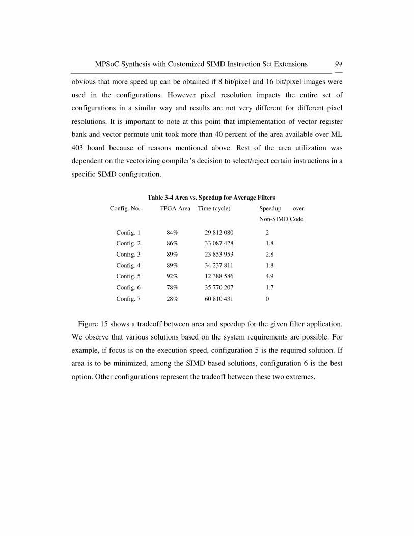
MPSoC Synthesis with Customized SIMD Instruction Set Extensions 94
obvious that more speed up can be obtained if 8 bit/pixel and 16 bit/pixel images were
used in the configurations. However pixel resolution impacts the entire set of
configurations in a similar way and results are not very different for different pixel
resolutions. It is important to note at this point that implementation of vector register
bank and vector permute unit took more than 40 percent of the area available over ML
403 board because of reasons mentioned above. Rest of the area utilization was
dependent on the vectorizing compiler’s decision to select/reject certain instructions in a
specific SIMD configuration.
Table 3-4 Area vs. Speedup for Average Filters
Config. No.
FPGA Area Time (cycle) Speedup over
Non-SIMD Code
Config. 1 84% 29 812 080 2
Config. 2 86% 33 087 428 1.8
Config. 3 89% 23 853 953 2.8
Config. 4 89% 34 237 811 1.8
Config. 5 92% 12 388 586 4.9
Config. 6 78% 35 770 207 1.7
Config. 7 28% 60 810 431 0
Figure 15 shows a tradeoff between area and speedup for the given filter application.
We observe that various solutions based on the system requirements are possible. For
example, if focus is on the execution speed, configuration 5 is the required solution. If
area is to be minimized, among the SIMD based solutions, configuration 6 is the best
option. Other configurations represent the tradeoff between these two extremes.
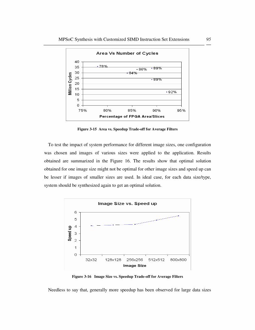
MPSoC Synthesis with Customized SIMD Instruction Set Extensions 95
Figure 3-15 Area vs. Speedup Trade-off for Average Filters
To test the impact of system performance for different image sizes, one configuration
was chosen and images of various sizes were applied to the application. Results
obtained are summarized in the Figure 16. The results show that optimal solution
obtained for one image size might not be optimal for other image sizes and speed up can
be lesser if images of smaller sizes are used. In ideal case, for each data size/type,
system should be synthesized again to get an optimal solution.
Figure 3-16 Image Size vs. Speedup Trade-off for Average Filters
Needless to say that, generally more speedup has been observed for large data sizes

MPSoC Synthesis with Customized SIMD Instruction Set Extensions 96
showing the suitability for SIMD for large data applications.
3.7 Conclusions
We propose in this chapter an automatic application specific SIMD based instruction
set extension flow for system on programmable chip. Concept of equivalence class
between/among SIMD and general-purpose processor instructions has been introduced
to create a system design space for synthesis of customized SIMD units. As a case
study, we have used AltiVec based SIMD unit along with PowerPC-405 embedded
processor and generated suitable architectures for image processing applications along
with their extended instruction set and the modified applications that can execute
themselves over the synthesized hardware. Results of area and application execution
times show that significant efficiency improvement can be achieved through the use of
our SIMD based synthesis methodology while keeping area consumption very low with
regard to a full standard instruction set extension. Finally, this work establish direct link
between vectorizer tools performance and associated SIMD hardware support in a
vectorizer-SIMD unit codesign relationship. It should be clear that new vectorizing
techniques are needed which solve simultaneously the multi-objective optimization
problem of performance, area and energy efficient SIMD based acceleration techniques.
References: [3.1] K. Diefendorff and P. K. Dubey. How Multimedia Workloads Will Change Processor Design.
In IEEE Micro, pages 43–45, Sep 1997. [3.2] S. Oberman et al, “AMD 3DNow! Technology and the K6-2 Microprocessor”, In
HOTCHIPS10, 1998. [3.3] M. Phillip et al,”AltiVec Technology: Accelerating Media Processing Across the Spectrum”,
In HOTCHIPS10, Aug 1998. [3.4] S. K. Raman, V. Pentkovski, J. Keshava,“ Implementing Streaming SIMD Extensions on the
Pentium III Processor”. In IEEE Micro, volume 20(4), pages 47–57, July-August 2000 [3.5] Schmookler M, Putrino M, Roth C, Sharma M, Mather A, Tyler J, Nguyen H.V, Pham M.N,
Lent J “A Low-power, High-speed Implementation of a PowerPC Microprocessor Vector Extension”,14th IEEE Symposium on Computer Arithmetic, p.12, 1999

MPSoC Synthesis with Customized SIMD Instruction Set Extensions 97
[3.6] Linlay Gwennap, “AltiVec Vectorizes PowerPC Forthcoming Multimedia Extensions Improve on MMX ” Microprocvessor report, Volume 12, No. 6, May 11, 1998
[3.7] Virtex-4 FPGA Handbook August 2004 [3.8] ML 40x Evaluation Platform User Guide, UG080 (v2.0) P/N 0402337 February 28, 2005,
2004-2005 Xilinx, Inc. [3.9] Fei Sun; Ravi, S.; Raghunathan, A.; Jha, N.K , "Custom-instruction synthesis for extensible-
processor platforms", Computer-Aided Design of Integrated Circuits and Systems, IEEE Transactions on Volume 23, Issue 2, Feb. 2004 Page(s): 216 – 228
[3.10] Atasu, K.; Pozzi, L.; Ienne, P., "Automatic application-specific instruction-set extensions under microarchitectural constraints" Design Automation Conference, 2003. Proceedings Volume , Issue , 2-6 June 2003 Page(s): 256 – 261
[3.11] Clark, N.; Hongtao Zhong; Mahlke, S., "Processor acceleration through automated instruction set customization", Microarchitecture, 2003. MICRO-36. Proceedings. 36th Annual IEEE/ACM International Symposium on Volume , Issue , 3-5 Dec. 2003 Page(s): 129 – 140
[3.12] J. A. Fisher, “Customized instruction sets for embedded processors,” in Proc. Design Automation Conf., June 1999, pp. 253–257.
[3.13] M. Breternitz Jr. and J. P. Shen, “Architecture synthesis of high-performance application-specific processors,” in Proc. Design Automation Conf., June 1990, pp. 542–548.
[3.14] R. Cloutier and D. E. Thomas, “Synthesis of pipelined instruction set processors,” in Proc. Design Automation Conf., June 1993, pp. 583–588.
[3.15] P. M. Athanas and H. F. Silverman, “Processor reconfiguration through instruction-set metamorphosis,” IEEE Comput., vol. 26, pp. 11–18, Mar. 1993.
[3.16] J. K. Adams and D. E. Thomas, “The design of mixed hardware/software systems,” in Proc. Design Automation Conf., June 1996, pp. 515–520.
[3.17] A. Kitajima, M. Itoh, J. Sato, A. Shiomi, Y. Takeuchi, and M. Imai, “Effectiveness of the ASIP design system PEAS-III in design of pipelined processors,” in Proc. Asia South Pacific Design Automation Conf., Jan. 2001, pp. 649–654.
[3.18] H. Choi, J. H. Yi, J.-Y. Lee, I.-C. Park, and C.-M. Kyung, “Exploiting intellectual properties in ASIP designs for embedded DSP software,” in Proc. Design Automation Conf., June 1999, pp. 939–944
[3.19] A. Pyttel, A. Sedlmeier, and C. Veith, “PSCP: A scalable parallel ASIP architecture for reactive systems,” in Proc. Design Automation Test Eur. Conf., Mar. 1998, pp. 370–376.
[3.20] K. Buchenrieder, A. Pyttel, and C. Veith, “Mapping statechart models onto an FPGA-based ASIP architecture,” in Proc. Eur. Design Automation Conf., Sept. 1996, pp. 184–189.
[3.21] D. Goodwin and D. Petkov, “Automatic generation of application specific processors”, In Proc. of the 2003 International Conference on Compilers, Architecture, and Synthesis for Embedded Systems, pages 137-147, 2003.
[3.22] N. Clark, H. Zhong, and S. Mahlke, “Processor acceleration through automated instruction set customization.” ,In Proc. of the 36th Annual International Symposium on Microarchitecture, pages 129-140, Dec. 2003.
[3.23] I. Huang. “Co-Synthesis of Instruction Sets and Microarchitectures”, PhD thesis, University of Southern California, 1994.
[3.24] F. Sun et al., “Synthesis of custom processors based on extensible platforms”, In Proc. of the 2002 International Conference on Computer Aided Design, pages 641-648, Nov. 2002.
[3.25] P. Brisk, A. Kaplan, M. Sarrafzadeh, “Area-Efficient Instruction Set Synthesis for Reconfigurable System-on-Chip Designs” Proceedings of Design Automation Conference, 41st Conference on (DAC'04) pp. 395-400,2004
[3.26] Atasu, K., Pozzi, L., and Ienne, “Automatic Application-Specific Instruction Set Extensions under Microarchitectural Constraints.”, Design Automation Conf. (DAC), 2003.
[3.27] V. Raghunathan, A. Raghunathan, M. B. Srivastave, M. D. Ercegovac, “High Level Synthesis with SIMD Units”, Proceedings of the 15th International Conference on VLSI Design (VLSID.02), 2002

MPSoC Synthesis with Customized SIMD Instruction Set Extensions 98
[3.28] N. Togawa, M. Yanagisawa, T. Ohtsuki, “A Hardware/Software Cosynthesis System for Digital Signal Processor Cores” IEICE Trans. Fundamentals, Vol E83-A, NO.11, November 1999
[3.29] P. Faraboschi et al, ”Lx: a technology platform for customizable VLIW embedded processing”, In ISCA, 2000.
[3.30] Altera. Nios embedded processor system development. http:// www.altera.com/products/ip/processors/nios/nio-index.html.
[3.31] R. E. Gonzalez, “Xtensa: A configurable and extensible processor.” IEEE Micro, 20(2), 2000. [3.32] Velocity Engine: http://developer.apple.com/hardware/ve/index.html [3.33] http://developer.apple.com/hardware/ve/algorithms.html#transpose [3.34] CHUD Tools( Amber, Shark, MONster):
http://developer.apple.com/tools/performance/overview.html [3.35] SIMG4:http://developer.apple.com:/Developer/Documentation/CHUD/SimG4_Users_Guide.p
df [3.36] Talla D, John L, Burger D “Bottlenecks in Multimedia Processing with SIMD Style
Extensions and Architectural Enhancement” IEEE Transactions on Computers, VOL. 52, NO. 8, AUGUST 2003 page 1015 – 1031
[3.37] Dorit Nicholas, “Autovectorization in GCC”, GCC Developers’ Summit, pp 105-117, 2004 [3.38] VAST Code Optimizer, Available: http://www.crescentbaysoftware.com/vast_altivec.html [3.39] D. Etiemble, L. Lacassagne,“16-bit FP sub-word parallelism to facilitate compiler
vectorization and improve performance of image and media processing.”, Proceedings of International Conference on Parallel Processing, Canada, Aug. 2004.
[3.40] PowerPC Processor reference Guide-Embedded Development Kit EDK 7.1i-UG 018(v 3.0) August 20, 2004
[3.41] Platform Specification Format Reference Manual- Embedded Development Kit EDK 7.1i-UG 131 (v3.0) Aug 20, 2004
[3.42] Xilinx ISE 7.1i Core Generator user Guide [3.43] Xilinx ISE 7.1 Synthesis and Verification User Guide [3.44] ModelSIM SE User’s manual v6.0a, Sept. 24, 2004 [3.45] I. Kuroda, T. Nishitani, ”Multimedia processors”, Proceedings of the IEEE 86 (6) (1998)
1203–1221. [3.46] K. Kim, R. Karri, and M. Potkonjak, “Synthesis of application specific programmable
processors,” in Proc. Design Automation Conf., June 1997, pp. 353–358. [3.47] I.-J. Huang and A. M. Despain, “Generating instruction sets and microarchitectures from
applications,” in Proc. Int. Conf. Computer-Aided Design, Nov. 1994, pp. 391–396. [3.48] K. Kucukcakar, “An ASIP design methodology for embedded systems,” in Proc. Int. Symp.
Hardware/Software Codesign,May 1999, pp. 17–21. [3.49] V. S. Lapinski, “Algorithms for compiler-assisted design space exploration of clustered VLIW
ASIP datapaths,” Ph.D. dissertation, Elect. And Comput. Eng. Dept., Univ. Texas, Austin, May 2001.
[3.50] S. Aditya, B. R. Rau, and V. Kathail, “Automatic architectural synthesis of VLIW and EPIC processors,” in Proc. Int. Symp. System-Level Synthesis, Nov. 1999, pp. 107–113.
[3.51] W. Zhao and C. A. Papachristou, “An evolution programming approach on multiple behaviors for the design of application specific programmable processors,” in Proc. Eur. Design Test Conf., Mar. 1996, pp. 144–150.
[3.52] http://developer.apple.com/hardwaredrivers/ve/instruction_crossref.html

MPSoC Synthesis with Customized SIMD Instruction Set Extensions 99
4. System Level Design Space Exploration
With the increasing complexity of modern embedded systems, design and
verification tasks are becoming increasingly complex. A modern System on Chip (SoC)
design consists of several cores and Moore's law predicts continuity in this trend for
several years to come [9]. With this enormous complexity, it is becoming more and
more important to take several important system decisions in the early stages of a
project as knowledge of wrong design decision at later stages in system design and late
bugs can result in longer time to market, huge re-spin costs and even collapse of the
project. Traditional techniques based on hardware modeling using VHDL and Verilog
while software modeling using C/C++ is too much detailed and hence it is impossible to
have system level view based on these models in early stages of project. It is important
to have faster design approaches to model a less detailed system in the beginning of
project design cycle. Transaction level modeling solves this problem.
Concept of transaction level modeling is to abstract all communication details from
the design. VHDL and Verilog based RTL (Register Transfer Level) models are
accurate at pin level and cycle level. A designer has to model every aspect of
communication in a detailed manner. Fig. 1 explains the difference between TLM
(Transaction Level Modeling) vs. RTL approaches of modeling and shows one of the

MPSoC Synthesis with Customized SIMD Instruction Set Extensions 100
benefits of using transaction level modeling. We can see that in TLM, several pin level
operations are wrapped in a single transaction level call and this transaction level call
abstracts further pin level details from designers view. Instead of sending individual
signals one by one on various pins, a whole transaction is sent to an abstract port
connected to a module. As a result, systemC based simulation results prove to be much
faster than RTL level simulation results for larger design sizes.
Figure 4-1 Transaction Level Modeling vs. Register Transfer Level
Benefits of Transaction Level Modeling don’t end at its simulation speed. Rather,
TLM’s wide acceptance as a preferred modeling technique for electronic systems is
driven by a lot of potential benefits obtained because of its introduction in a system
design flow. These benefits include:
- Faster system design space exploration
- Easier system modeling
- Faster simulation speeds
- Early start of software development
- Avoidance of late bugs in a project.

MPSoC Synthesis with Customized SIMD Instruction Set Extensions 101
- Hence: Shorter Times to Market for a product.
As a result, Transaction level modeling (TLM) has emerged as a key modeling
approach for ESL (Electronic System Level) design and a lot of tools[64][65] and
design flows has been proposed based on transaction level modeling. At the same time,
behavioral synthesis is considered as the next higher level abstraction layer for hardware
synthesis which help hardware designer model the hardware at higher abstraction layer
than RTL and the synthesis tool translates it to low gate level hardware details. In the
following sections, we introduce some of the tools available in academia and industry
related to TLM and Behavioral synthesis. In section 3.3, we will present a case study in
which we introduced energy estimation in the design flow using a behavioral synthesis
tool. Then we will present a brief overview of existing design methodologies for system
level design. In Section 3.4, we will propose our platform based SystemC TLM system
level design methodology for embedded applications. This methodology emphasizes on
components based software design and high level (TLM) modeling and simulation
along with the usage of behavioral synthesis tools to accelerate the system design
process to meet strict time to market constraints in the industry. A case study will be
presented in Section 3.5. This case study is based on embedded system design of
intelligent vehicles. Results of the case study show the effectiveness of our
methodology. Chapter ends with concluding remarks on effectiveness of our approach.
4.1 Platform Based TLM Design Process
Platform have been proposed by semiconductor manufacturers in an effort to ease
system level design and allows system designers to concentrate on essential issues such
as hardware-software partitioning, system parameters tuning and design of specific
hardware accelerators. This makes the reuse of platform based designs easier than
specific designs.

MPSoC Synthesis with Customized SIMD Instruction Set Extensions 102
4.1.1 IBM’s Platform Driven Design Methodology
The IBM Coreconnect platform [8] described in the figure2 below allows the easy
connection of various components, system core and peripheral core to the coreconnect
bus architecture. It includes IPs of PLB to OPB and OPB to PLB bridges and Direct
Memory Access (DMA) Controller, OPB-attached External Bus Controller (EBCO),
Universal Asynchronous Receiver/Transmitter (UART), Universal Interrupt Controller
(UIC) and Double Data Rate (DDR) Memory Controller. Several other peripherals are
available among them CAN controllers. The platform does not specify a specific
processor core although IBM family of embedded PowerPC processors connection is
straightforward. This platform which mainly specifies a model based platform have all
associated tools and libraries for quick ASIC or FPGA platform design. System core
and peripheral core can be any type of user designed component whether hardware
accelerators or specific peripherals and devices.
Figure 4-2 IBM CoreConnect Platform

MPSoC Synthesis with Customized SIMD Instruction Set Extensions 103
a. IBM SystemC TLM Platform
The SystemC IEEE Standard [9] is a system level modeling environment which
allows the design of various abstractions levels of systems. It spawns from untimed
functional to cycle accurate. In between, design space exploration with hardware-
software partitioning is conducted with timed functional level of abstraction. Using the
Model-Driven Architecture (MDA) terminology [27] we can model computation
independent model (CIM), platform independent model (PIM) and platform specific
model (PSM). Besides, SystemC can model hardware units at RTL level and be
synthesizable for various target technologies using tools such as Synopsys [10] and
Celoxica [11] which in turn allows multiobjective SystemC space exploration of
behavioral synthesis options on area, performance and power consumption [12] since
for any system all three criteria cannot be optimally met together.
Figure 4-3 SystemC System Design Flow

MPSoC Synthesis with Customized SIMD Instruction Set Extensions 104
This important point allows SystemC abstraction level platform based evaluation
taking into account area and energy aspects and this for proper design space exploration
with implementation constraints. In addition to these levels of abstraction Transaction
Level Modeling abstraction level [17,18] have been introduced to fasten simulation of
communications between components by considering communications exchange at
transaction level instead of bus cycle accurate levels. Benefits of TLM abstraction level
design have been clearly demonstrated [17-18].
Using the IBM CoreConnect SystemC Modeling Environment PEK [14],[66]
designers are able to put together SystemC models for complete systems including
PowerPC processors, CoreConnect bus structures, and peripherals. These models may
be simulated using the standard OSCI SystemC[9] runtime libraries and/or vendor
environments. The IBM CoreConnect SystemC Modeling Environment TLM platform
models and environment provide designers with a system simulation/verification
capability with the following characteristics:
• Simulate real application software interacting with models for IP cores and the
environment for full system functional and timing verification possibly under
real-time constraints
• Verify that system supports enough bandwidth and concurrency for target
applications
• Verify core interconnections and communications through buses and other
channels
• Model the transactions occurring over communication channels with no
restriction on communication type
These objectives are achieved with additional practical aspects such as simulation
performance must be enough to run a significant software application with an operating
system booted on the system . In addition, the level of abstraction allows that:
• Computation (inside a core) does not need to be modeled on a cycle-by-cycle
basis, as long as the input-output delays are cycle-approximate which implies
that for hardware accelerators both SystemC and C is allowed,

MPSoC Synthesis with Customized SIMD Instruction Set Extensions 105
• Inter-core communication must be cycle-approximate, which implies cycle-
approximate protocol modeling
• The processor model does not have to be a true architectural model; a software-
based Instruction Set Simulator (ISS) can be used, provided that the performance
and timing accuracy are adequate
In order to simulate real software, including the initialization and internal register
programming, the models must be "bit-true" and register accurate, from an API point of
view. That is, the models must provide APIs to allow programming of registers as if the
user were programming the real hardware device, including the proper number of bits
and address offsets. Internal to the model, these "registers" may be coded in any way
(e.g., variables, classes, structs, etc) as long as their programming API make them look
like real registers to the users. Models need not be a precise architectural representation
of the hardware. They may be behavioral models as long as they are cycle-approximate
representations of the hardware for the transactions of interest (i.e., the actual
transactions being modeled). There may be several clocks in the system (e.g., CPU,
PLB and OPB). All models must be "macro-synchronized" with one or more clocks.
This means that for the atomic transactions being modeled, the transaction boundaries
(begin and end) are synchronized with the appropriate clock. Inside an atomic
transaction, there is no need to model it on a cycle-by-cycle basis. An atomic transaction
is a set of actions implemented by a model, which once started, is finished. That is, it
cannot be interrupted. Our system design approach using IBM’s PowerPC 405
Evaluation Kit (PEK) allows designers to evaluate, build, and verify SoC designs using
Transaction level modeling. However PEK does not provide synthesis (area estimate)
or energy consumption estimation capability in its toolset.
b. SW Development, Compilation, Execution, Debugging
In PEK, The PowerPC processors (PPC 405/PPC450) are modeled using an
instruction-set simulator (ISS). The ISS is instantiated inside a SystemC wrapper
module, which implements the interface between the ISS and the PLB bus model. The
ISS runs synchronized with the PLB SystemC model (although the clock frequencies
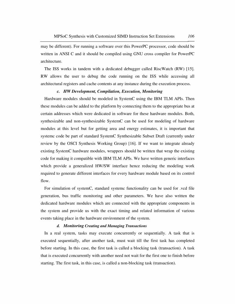
MPSoC Synthesis with Customized SIMD Instruction Set Extensions 106
may be different). For running a software over this PowerPC processor, code should be
written in ANSI C and it should be compiled using GNU cross compiler for PowerPC
architecture.
The ISS works in tandem with a dedicated debugger called RiscWatch (RW) [15].
RW allows the user to debug the code running on the ISS while accessing all
architectural registers and cache contents at any instance during the execution process.
c. HW Development, Compilation, Execution, Monitoring
Hardware modules should be modeled in SystemC using the IBM TLM APIs. Then
these modules can be added to the platform by connecting them to the appropriate bus at
certain addresses which were dedicated in software for these hardware modules. Both,
synthesizable and non-synthesizable SystemC can be used for modeling of hardware
modules at this level but for getting area and energy estimates, it is important that
systemc code be part of standard SystemC Synthesizable Subset Draft (currently under
review by the OSCI Synthesis Working Group) [16]. If we want to integrate already
existing SystemC hardware modules, wrappers should be written that wrap the existing
code for making it compatible with IBM TLM APIs. We have written generic interfaces
which provide a generalized HW/SW interface hence reducing the modeling work
required to generate different interfaces for every hardware module based on its control
flow.
For simulation of systemC, standard systemc functionality can be used for .vcd file
generation, bus traffic monitoring and other parameters. We have also written the
dedicated hardware modules which are connected with the appropriate components in
the system and provide us with the exact timing and related information of various
events taking place in the hardware environment of the system.
d. Monitoring Creating and Managing Transactions
In a real system, tasks may execute concurrently or sequentially. A task that is
executed sequentially, after another task, must wait till the first task has completed
before starting. In this case, the first task is called a blocking task (transaction). A task
that is executed concurrently with another need not wait for the first one to finish before
starting. The first task, in this case, is called a non-blocking task (transaction).

MPSoC Synthesis with Customized SIMD Instruction Set Extensions 107
Transactions may be blocking or non-blocking. For example, if a bus master issues a
blocking transaction, then the transaction function call will have to complete before the
master is allowed to initiate other transactions. Alternatively, if the bus master issues a
non-blocking transaction, then the transaction function call will return immediately,
allowing the master to do other work while the bus completes the requested transaction.
In this case, the master is responsible for checking the status of the transaction before
being able to use any result from it. Blocking or non-blocking transactions are not
related to the amount of data being transferred or to the types of transfer supported by
the bus protocols. Both multi-byte burst transfers as well as single-byte transfers may be
implemented as blocking or non-blocking transactions.
When building a platform, the designer has to specify the address ranges of memory
and peripherals attached to the PLB/OPB busses. The ISS, upon encountering an
instruction which does a load/store to/from a memory location on the bus, will call a
function in the wrapper code which, in turn, issues the necessary transactions on the
PLB bus. The address ranges of local memory, bus memory, cache sizes, cacheable
regions, etc, can all be configured in the ISS and the SystemC models.
e. IP Parameterization
Various parameters can be adjusted for the processor IPs and other IPs implemented
in the system. For a processor IP, when the ISS is started, it loads a configuration file
which contains all the configurable parameter for running the ISS. The configuration
file name may be changed in the Tcl script invoking the simulation. The parameters in
the file allow the setting of local memory regions, cache sizes, processor clock period,
among other characteristics. For example, we can adjust the value of Data and
Instruction Cache sizes to be 0, 1024, 2048, 4096, 8192, 16384, 32768 and 65536 for
the 405 processor. Besides setting the caches sizes, the cache regions need to be
configured. That is, the user needs to specify which memory regions are cacheable or
not. This is done by setting appropriate values into special purpose registers DCCR and
ICCR. These are 32-bit registers, and each bit must be set to 1 if the corresponding
memory region should be cacheable

MPSoC Synthesis with Customized SIMD Instruction Set Extensions 108
The PowerPC uses two special purpose registers (SPRs) for enabling and configuring
interrupts. The first register is the Machine State Register (MSR) which controls
processor core functions, such as the enabling and disabling of interrupts and address
translation. The second register is the Exception Vector Prefix Register (EVPR). The
EVPR is a 32-bit register whose high-order 16 bits contain the prefix for the address of
an interrupt handling routine. The 16-bit interrupt vector offsets are concatenated to the
right of the high-order bits of the EVPR to form the 32-bit address of an interrupt
handling routine. Using RiscWatch commands and manipulating startup files to be read
from RiscWatch, we can enable/disable cachebility, interrupts and vary the cache sizes.
While on the other hand, CPU, Bus and Hardware IP configuration based parameters
can be adjusted in top level file for hardware description where the hardware modules
are being initialized.
Provision of these IPs and ease of modeling makes IBM TLM a suitable tool for
platform generation and its performance analysis early in the system design cycle.
4.1.2 PowerPC Evaluation Kit
IBM's TLM library and PowerPC Evaluation Kit (Pek) also allows designers to
generate transaction level models based on Coreconnect [8,67] bus architecture. We
have used PeK for modeling transaction level models for the work done in this chapter.
Rest of the section introduces the PeK environment, IBM TLM libraries and various
functionalities it provides to system designer.
4.1.2.1 IP Libraries
IBM TLM APIs facilitate the creation of system-level models, assembled from
existing IBM SystemC core models, and the development of additional models which
conform to Open SystemC Initiative (OSCI) standards. IP library provided with these
APIs include Instruction Set Simulators of PowerPC405, PowerPC440, standard core-
connect busses including Processor Local Bus (PLB), On-chip Peripheral Bus (OPB)
and Device Control Register Bus (DCR). It also includes IPs of PLB to OPB and OPB
to PLB bridges and Direct Memory Access (DMA) Controller, OPB-attached External

MPSoC Synthesis with Customized SIMD Instruction Set Extensions 109
Bus Controller (EBCO), Universal Asynchronous Receiver/Transmitter (UART),
Universal Interrupt Controller (UIC) and Double Data Rate (DDR) Memory Controller
(See Fig. 4). Following the SystemC/ IBM TLM specification, system designer can
easily write and add the dedicated Hardware Module IPs and add them to a system
details of which will be explained in methodology section.
Figure 4-4 PowerPC 405 block diagram for the PEK SoC design
4.1.2.2 Processor Instruction Set Simulator
The PowerPC processors (PPC 405/PPC450) are modeled using an instruction-set
simulator (ISS). The PowerPC 405 processor core consists of a five-stage pipeline,
separate instruction and data cache units, a virtual memory management unit (MMU),
three timers, debug and interfaces to other functions. The core provides a range of I/O
interfaces that simplify the attachment of on-chip and off-chip devices. The ISS is
instantiated inside a SystemC wrapper module, which implements the interface between
the ISS and the PLB bus model. The ISS runs synchronized with the PLB SystemC
model (although the clock frequencies may be different). The ISS works in tandem with
a dedicated debugger called RiscWatch (RW). RW allows the user to debug the code
running on the ISS and view all architectural registers and cache contents. In order to
generate code to run on the ISS, users must use the GNU PowerPC Cross-Compiler.

MPSoC Synthesis with Customized SIMD Instruction Set Extensions 110
4.1.2.3 Chip Bench System Level Design Tool
On top of all above IP libraries, Instruction set simulator and transaction level modeling
libraries, PeK also provides a graphical tool to model complete system with simple
"drag and drop" type of operations. Designer can write new IP components and add
them to libraries graphical environment along with IP libraries already included in PeK.
Once IP components are added to the library, their reuse becomes very easy in a
graphical environment.
Figure 4-5 Graphical Modeling Using CBSLD
Chip bench System Level design (CBSLD) tool automatically generates top level
files, compiles them and converts them into executable form. It also allows performance
analysis in terms of many parameters i.e. bus throughput, average power, idle time etc.
A Snapshot of graphical environment and performance evaluation windows is shown in
Fig.5. In this chapter, PeK and IBM TLM libraries have been used for modeling and
performance analysis of all the platforms.

MPSoC Synthesis with Customized SIMD Instruction Set Extensions 111
4.2 Behavioral Synthesis
While Transaction Level modeling allows acceleration at system level design,
behavioral synthesis allows design at higher levels of abstraction by automating the
translation and optimization of a behavioral description, or high-level model, into an
RTL implementation hence increasing productivity at IP/component level. It transforms
un-timed or partially timed functional models into fully timed RTL implementations.
Because a micro-architecture is generated automatically, designers can focus on
designing and verifying the module functionality. Design teams create and verify their
designs in an order of magnitude less time because it eliminates the need to fully
schedule and allocate design resources with existing RTL methods. This behavioral
design flow increases design productivity, reduces errors, and speeds verification.
As shown in fig. 6, the behavioral synthesis process incorporates a number of
complex stages. This process starts with a high-level language description of a module's
behavior, including I/O actions and computational functionality. Several algorithmic
optimizations are performed to reduce the complexity of a result and then the
description is analyzed to determine the essential operations and the dataflow
dependencies between them.

MPSoC Synthesis with Customized SIMD Instruction Set Extensions 112
Figure 4-6 Generalized Behavioral Synthesis Flow
The other inputs to the synthesis process are a target technology library, for the
selected fabrication process, and a set of directives that will influence the resulting
architecture. The directives include timing constraints used by the algorithms, as they
create a cycle-by-cycle schedule of the required operations. The allocation and binding
algorithms assign these operations to specific functional units such as adders,
multipliers, comparators, etc.
Finally, a state machine is generated that will control the resulting datapath's
implementation of the desired functionality. The datapath and state machine outputs are
in RTL code, optimized for use with conventional logic synthesis or physical synthesis
tools.
4.2.1 Orinoco Dale: A Brief Introduction
Orinoco dale is a tool based on behavioral synthesis from C description of a
hardware IP which allows system designers to estimate area and energy consumption

MPSoC Synthesis with Customized SIMD Instruction Set Extensions 113
for various IP components in a system. Design flow of Orinoco is shown in the Fig.7.
Input to dale design flow is source code written in C/SystemC along with a set of
constraints for area and speed. Orinoco synthesizes the C/C++ description and generates
estimation information for various modules in the description.
Figure 4-7 Behavioral Synthesis Flow using Orinoco Dale
With the help of Orinoco Dale, ASIC designers can accurately estimate power
requirement and detailed power consumption statistics for low power wireless
embedded systems.
4.3 Introducing Power Estimation in High Level TLM Design Flow:
A Case Study
With the evolution of modern embedded systems in general and wireless embedded
systems in particular, it is becoming more and more important to take into account the
area and energy consumption issues in consideration during system design at early
stages. Importance of energy consumption in modern embedded systems can be
understood by the trends predicted by Gelsinger’s law. According to it, new generation

MPSoC Synthesis with Customized SIMD Instruction Set Extensions 114
micro architectures use twice as many transistors for a 40 percent increase in
performance, which in other words predict that [56] “By 2010 high-end processors
would radiate the same heat volume per square centimeter as a rocket nozzle, by 2015 –
as the Sun’s surface”. While dealing with the heating issues is considered one of the
bottlenecks in future embedded systems, we believe that it is very important to enhance
the traditional system level design methodologies by incorporating energy estimation
methodologies to get full potential benefits offered by TLM. Behavioral Synthesis
techniques based on C++/SystemC provide us an opportunity to estimate area/energy of
various components of the system without implementing them at RTL level (in
VHDL/Verilog). A few tools have been commercially proposed that allow the
behavioral synthesis of C++/ SystemC description of hardware modules. In this chapter,
we propose an extension to TLM based design methodologies by incorporating these C
based behavioral synthesis techniques in the design flow which allows us to take into
account the crucial factors of area and energy estimation at the early stage of system
design which in returns increases the productivity, reduces the time to market and
avoids the energy/area based bottlenecks at the later stages in system design.
4.3.1 Power Estimation: Related Work
Work on power estimation has been done at various layers of abstraction. Most of the
work has been done in RTL and lower layers of abstraction. However a little work has
been done on power estimation at TLM level of abstraction. Existing work as presented
in [57], [58], [59], and [60] emphasizes on instruction based, function based and state
based power analysis. However these power analysis techniques are based on post
partitioning architectural analysis of the system where partitioning decisions of the
system has already been taken and energy is being estimated for communication taking
place between various components. These techniques only estimate the power
consumption of communication part of the system and hence these approaches can’t
prove to be useful for system partitioning decisions.
Our approach emphasizes on area and energy estimation for various IP models in a
system before the partitioning decisions has been taken. Instead of proposing lower

MPSoC Synthesis with Customized SIMD Instruction Set Extensions 115
level (instruction or transaction level) power and area estimation, we perform IP level
area and energy estimation using existing work on behavioral synthesis of system level
design languages. Lot of work has been done in academia on behavioral synthesis with
SystemC [70][71][72]. For example, [70] have presented a synthesis environment and
the corresponding synthesis methodology, based on traditional compiler generation
techniques, which incorporate SystemC, VHDL and Verilog to transform existing
algorithmic software models into hardware system implementations. In [71], authors
address the problem of deriving exact Finite State Machines (FSMs) from SystemC
descriptions which is the first part of behavioral synthesis methodologies. In an effort to
extend synthesis to object oriented constructs of C++ language, [72] present an
approach to object-oriented hardware design and synthesis based on SystemC. Behavior
synthesis problem is multi-objective in nature where synthesis tools allow the hardware
designers to customize the behavioral synthesis process through various options which
constitute a huge design space. In this situation, solution exists of a set of optimized
results represented in the form of pareto curves and pareto surfaces. In [69], Hammami
et al. present a methodology that allows the designers to detect the best synthesis results
on area, performance and power consumption estimation through an automatic
exploration of synthesis results. A few commercial tools [10],[11] are also available for
area estimation for behavioral modules. Synopsys SystemC compiler was perhaps the
first commercial efforts to synthesize behavioral code written in ESL languages.
Celoxica’s Agility can synthesize SystemC behavioral description of hardware modules
and give the area estimation requirements for various ASIC and FPGA based
architectures. Orinoco Dale [61] is another tool that estimates area and energy for C
description of an application. We perform area and energy estimates of various IP
components in the system before actually modeling the system in TLM. The area and
energy estimation information is fed into the TLM model of the system where we
partition the system by automatically exploring the system design space based on the
given information. To our knowledge, we are the first ones to propose a design flow that
uses TLM modeling for system design space exploration and includes area and energy
estimation information during the partitioning process.

MPSoC Synthesis with Customized SIMD Instruction Set Extensions 116
4.3.2 Area/Energy Estimation Extension to Traditional TLM Design Flow
Our target platform for the synthesized system is shown in Fig. 8. Starting from an
application written in C/C++, we plan to have a system built around a general purpose
processor (in our case IBM PowerPC 405) and extended by appropriate hardware
accelerators that provide good system performance improvement without requiring too
much increase in area and energy consumption.
Figure 4-8 Target Platform Built using IBM TLM
a) Application Development:
The design flow is shown in Fig. 9. At the first stage, application is written in
C/C++. This application description can be run over a general purpose processor
describing the system without hardware accelerators. That means, at this stage all the
functionality is implemented in software part and no hardware accelerators are present
in the platform. Although our methodology is independent of the application
development procedure, we use image processing chain development approach which
can be seen as task graphs where each image processing operator i.e. Gaussian, Sobel,
conservative filters is a node of the task graph. Starting the system synthesis this way
assures rapid development of the initial software. Keeping in mind that software
development takes a significant time in current system design approaches; our

MPSoC Synthesis with Customized SIMD Instruction Set Extensions 117
approach saves a lot of time by avoiding software development starting from scratch.
b) Behavioral Synthesis and Extended Task Graph Generation:
Then this application is forwarded to a C/C++ synthesis tool. Because of reasons
explained in previous sub-sections, we use Orinoco dale as a tool of our choice for the
estimation of area and energy consumption. Dale provides the application
requirements in terms of area/energy constraints which are stored in a database. On
the other hand, task graph is extracted from the software that is extended with the
information received from dale. This extended task graph allows the design space
exploration engine to provide the information about various tasks and their hardware
implementation requirements. There are several tools for task graph extraction from
an application description [15] in C and any of the tools can be used for this purpose.
Figure 4-9 HW/SW Codesign Flow
c) Platform Development Details:
In the beginning of our design methodology, our platform consists of a general

MPSoC Synthesis with Customized SIMD Instruction Set Extensions 118
purpose processor. Processor is connected to high speed PLB as master device while a
RAM is connected to PLB bus as a slave. In later configurations, all hardware
accelerators are also added to the platform as slave to the PLB which can accommodate
several slaves. PowerPC has a 32 bit memory address space and hence it can address
any slave component that is mapped to a specific part of this address space. A new IP is
written in systemC and added to the platform in a top level files where objects of all
files are created and mapped with each other.
Communication between processor and memory is done through transactions. A
transaction is a set of operations performed by a set of pins and spread over multiple
cycles performing a high level operation: sending a chunk of data from/to processor
to/from memory. In our environment, a Transaction is initiated by processor which is
triggered by software command. To send a transaction to a slave connected to PLB bus,
programmer needs to define a variable pointing to that address and then variable is
assigned a value (See Fig. 10). During execution, ISS reads the commands and forwards
the value to the bus where arbiter forwards it to IP interface unit responsible for
memory map management of the slave IPs connected to it.
On the other hand, slave IP is implements a generic slave interface. In order to send
and receive transaction, each hardware accelerator should implement function provided
by slave interface shown in Fig.10.

MPSoC Synthesis with Customized SIMD Instruction Set Extensions 119
Figure 4-10 Implementing Transaction Read and Write Functions on Slave Hardware
Accelerators
Once memory mapping is done, top level module have been initialized and software
has been updated and recompiled, simulations can be performed and performance
results can be obtained for a certain configuration.
d) Design Space Exploration Engine:
Design space exploration engine facilitates the automatic generation of various
platforms and performance simulation for automatic partitioning of image processing

MPSoC Synthesis with Customized SIMD Instruction Set Extensions 120
application is done. An image processing chain consisting of n nodes has n² possibilities
for system’s partitioning into hardware and software. Our tool based on this framework
proposes a methodology to automatically check these n² possibilities and give us the
performance results for each of the configuration. For automatic generation of a
specific configuration, our tool inspects the functionality to be sent to hardware, and
based on the information converts a SW computation function to a data transferring
function between general purpose processor and hardware accelerator. This is done
simply by reading the function definition and inspecting the input, output image
parameters along with their heights and widths. After reading the parameters, body of
the software function is removed and replaced with data transfer operations to send and
receive images to hardware module. (See fig. 11). This way, we make sure that
software for a specific configuration is updated with minimum possible changes and
there remains no need to debug and verify its functionality because of cleanliness and
simplicity of our approach.
On the other hand, hardware accelerator is embedded into a generic module that
communicates with the software running over the general purpose processor (GPP) to
receive/send images from processor to the hardware accelerator. On the hardware side,
as mentioned above, the communication interface (HW/SW interface) receives the data
along with the information about number of images, their height and widths and the
information about output images. The C code of the operator being implemented in
HW is copied from SW to a function inside the HW accelerator module and estimated
computation times calculated in step 2 where an operator was actually synthesized in
behavioral systemC are passed as approximates delays in the top level module
combining all the components in the system. Lastly, scheduling of various operators in
the chain is done to make sure that data communication overhead is reduced to achieve
maximum speedup for a configuration. Hence, using our approach we can automatically
shift an operator implemented in software to a hardware giving us realistic performance
estimates without a need to change the HW/SW interface for each configuration.

MPSoC Synthesis with Customized SIMD Instruction Set Extensions 121
Figure 4-11 Transforming SW Computation into Communication Tasks
It should be noticed that shifting functionality from hardware to software or software
to hardware is a straightforward task as both hardware and software (hence the complete
system) is described in C and only work required to move a functionality from software
to hardware is to replace computation with a data transfer function in software and
adding computation into hardware along with synthesis information obtained from dale.
Similarly, for area and energy estimation, no alteration is required for original
application description as dale produces area and energy estimation requirement from
the C description. Hence, no major work is required for translating C to hardware
description languages or vice versa during the complete design flow.

MPSoC Synthesis with Customized SIMD Instruction Set Extensions 122
e) Parameterization
In the last step, tuning of some soft parameters is performed to improve the
application performance and resource usage. Examples of such soft parameters include
interrupt and arbitration priorities and bus width. We deal with the problem manually
instead of relying on a design space exploration algorithm and our approach is to start
tuning the system with the maximum resources available and keep on cutting down the
resource availability until the system performance remains well within the limits and
bringing down the value of a parameter doesn’t dramatically affect system performance.
4.3.3 Experiment Environment and Results
We have tested over approach using IBM’s PowerPC 405 Evaluation Kit (PEK) that
allows designers to evaluate, build, and verify SoC designs using Transaction level
modeling. As mentioned above, our target is to synthesize a system based on a general
purpose processor (in our case, IBM PowerPC 405) and extended with the help of
suitable hardware accelerators to improve the system performance significantly. A gcc
Figure 4-12 Control Data Flow Graph of Filters in the Application

MPSoC Synthesis with Customized SIMD Instruction Set Extensions 123
based cross compiler for PowerPC405 was used to compile the software while SystemC
compiler was used to compiler hardware modules. In our application, we had three
components in an image processing chain: median, conservative and average filters. For
our simulation, our general purpose processor (PowerPC 405) was running at 333 MHz
with 16K of Data and instruction caches.
Figure 12 shows the Control data flow graph (CDFG) generated by dale for each of
the filters while Fig.13, Fig. 14 and Fig. 15 show the area, energy and execution cycles
taken by the filters if synthesized using 180 nm process technology.
Energy Consumption of Filters
0500
10001500200025003000350040004500
Average Filter Conservative
Filter
Median Filter
Filter
En
erg
y (n
Ws)
Figure 4-13 Energy consumption requirements for filters
It should be noted that median filter is more expensive in terms of number of cycles
and energy consumption while conservative filter is slightly more expensive in terms of
area requirements. Results obtained from these tables are then forwarded to design
space exploration engine which adds the computation time estimations in TLM
description of these’ components and performs the simulation of various configurations.

MPSoC Synthesis with Customized SIMD Instruction Set Extensions 124
Area of Filters
010000200003000040000500006000070000
Average Filter Conservative
Filter
Median Filter
Filter
Are
a (S
q u
m)
Figure 4-14 Area requirements for filters
Execution Cycle of Filters
0
50000
100000
150000
200000
250000
Average Filter Conservative
Filter
Median Filter
Filter
Exe
cute
d C
ycle
s
Figure 4-15 Execution cycles taken by Filters
Figure 4-16 Heat Maps of Filters

MPSoC Synthesis with Customized SIMD Instruction Set Extensions 125
Table 1 shows the various configurations generated by the design space exploration
engine and the number of PowerPC cycles taken by the system for each of the
configuration. We can see that best speedup can be obtained if Median and
Conservative filters are implemented as hardware. However, looking at the high area
requirements of conservative filters, we can opt to keep the conservative filter in
software and hence configuration 1 gives a solution that is optimal both for area and
speedup requirements. It is important to mention here that the filter application is a
relatively simple application. That’s why, our design space exploration optioning for
partitioning are limited. However, our design space exploration engine can deal with
larger applications as well.
Table 4-1 Various configurations and Speed ups for Filters
Config. No. Hardware
Implementation
Time
(cycle)
Speedup
Over
Software
Version
1 Median 3897000 1.859
2 Average 7202000 1.006
3 Conservative 6630000 1.093
4 Median + Average 3493000 2.075
5 Median+
Conservative
2921000 2.481
6 Average+ Conservative 6028000 1.202
7 Software Version 7248000 1
4.3.4 Summarizing the Case Study
In this section, we have proposed a design flow of HW/SW codesign that incorporates
area and energy estimates in the existing TLM based system design flows. With the

MPSoC Synthesis with Customized SIMD Instruction Set Extensions 126
evolution of C based synthesis tools, it is becoming possible to enhance the existing
methodologies based on transaction level modeling to include area and energy estimates
as well. The design decisions taken at such higher levels provide a detailed insight of
the system design space to the system designer which helps him take partitioning
decisions while keeping in mind the factors of area and energy consumption as well.
4.4 A Platform based TLM Level Design Methodology for
Multimedia Application Synthesis
Transaction Level Modeling (TLM) and component based software development
approaches accelerate the process of an embedded system design and simulation and
hence improve the overall productivity. On the other hand, system level design
languages facilitate the fast hardware synthesis at behavioral level of abstraction. In this
section, we introduce an approach for Hardware/Software codesign of image processing
applications that combines platform based SystemC TLM and component based
software design approaches along with HW synthesis using SystemC to accelerate
system design and verification process.
It should be clear from Section XX that IBM PEK provides almost all important
aspects of system design. That’s why we have based our methodology for HW/SW
codesign on this tool. However, our methodology will be equally valid for all other tools
having similar modeling and simulation functionality. Our HW/SW codesign approach
has following essential steps:
� Image Processing Chain Development
� Software Profiling
� Hardware Modeling of Image Processing Operators
� Performance/Cost Comparison for HW/SW Implementations
� Platform generation, System Design Space Exploration
a) Image Processing Chain Development
Our system codesign approach starts from development of image processing chain
(IPC). Roughly speaking, an image processing chain consists of various image
processing operators placed in the form of directed graph according to the data flow

MPSoC Synthesis with Customized SIMD Instruction Set Extensions 127
patterns of the application. An image processing chain is shown in Fig.17 below.
Figure 4-17 Harris Corner Detector Chain
This IPC describes the working of a Harris corner detector. IPC development process
is very rapid as normally most of the operators are already available in the operator’s
library and they need only initialized in a top level function to form an image processing
chain and secondly it provides a very clean and modular way to optimize various parts
of the application without the need of thorough testing and debugging. In our case, we
have used coding guidelines as recommended by Numerical Recipes [22] which
simplifies the IPC development process even further.
b) Software Profiling
In this step, we execute the image processing chain over the PowerPC 405 IP
provided with PowerPC evaluation kit. Using RisCWatch commands, we get the
performance results of various software components in the system and detect the
performance bottlenecks in the system. Software profiling is done for various data and
instruction caches sizes and bus widths. This information helps the system designer take
the partitioning decisions in later stages.
c) Hardware Modeling of Image Processing Operators
In the next step of our system design approach, area and energy estimates are obtained

MPSoC Synthesis with Customized SIMD Instruction Set Extensions 128
for the operators implemented in the image processing chain. At SystemC behavioral
level, the tools for estimating area and energy consumption have recently been showing
their progress in the EDA industry. We use Celoxica’s agility compiler [11] for Area
estimation in our case but our approach is valid for any behavioral level synthesis tool
in the market. As we advocate the fast chain development through libraries containing
image processing operators, similar libraries can also be developed for equivalent
systemC image processing operators which will be reusable over a range of projects
hence considerably shortening the hardware development times as well. At the end of
this step, we have speed and area estimates for all the components of the image
processing chain to be synthesized. This information is stored in a database and is used
during HW/SW partitioning done in the next step.
Another important thing to be noted is that HW synthesis is also a multi-objective
optimization problem. Previously, [12] have worked over efficient HW synthesis from
SystemC and shown that for a given SystemC description, various HW configurations
can be generated varying in area, energy and clock speeds. Then the most suitable
configuration out of the set of pareto optimal configurations can be used in the rest of
the synthesis methodology. Right now, we don’t consider this HW design space
exploration for optimal area/energy and speed constraints but in our future work, we
plan to introduce this multi-objective optimization problem in our synthesis flow as
well.
d) Performance Comparison for HW/SW Implementations
At this stage of system codesign, system designer has profiling results of software as
well as hardware implementation costs and the performance of the same operator in the
hardware. So, in this stage performance of various individual operators is compared and
further possibilities of system design are explored.
e) Platform generation, System Design Space Exploration
Like traditional hardware/software codesign approaches, our target is to synthesize a
system based on a general purpose processor (in our case, IBM PowerPC 405) and
extended with the help of suitable hardware accelerators to significantly improve the
system performance without too much increase in the hardware costs. We have chosen

MPSoC Synthesis with Customized SIMD Instruction Set Extensions 129
PowerPC 405 as a general purpose processor in our methodology because of its
extensive usage in embedded system and availability of its systemC models that provide
ease of platform design based on its architecture. Our target platform is shown in fig 8.
Our target is to shift the functionality from image processing chain to the Hardware
accelerators such that system gets good performance improvements without too much
hardware costs.
In this stage, we perform the system level simulation. Based on the results of last
step, we generate various configurations of the system putting different operators in
hardware and then observing the system performance. Based on these results and
application requirements, a suitable configuration is chosen and finalized as a solution
to HW/SW codesign issue.
f) Parameter Tuning
In the last step of image processing chain synthesis flow, we perform the
parameterization of the system. At this stage, our problem becomes equivalent to
(Application Specific Standard Products) ASSP parameterization. In ASSP, hardware
component of the system is fixed; hence only tuning of some soft parameters is
performed for these platforms to improve the application performance and resource
usage. Examples of such soft parameters include interrupt and arbitration priorities.
Further parameters associated with more detailed aspects of the behavior of individual
system IPs may also be available. We deal with the problem manually instead of relying
on a design space exploration algorithm and our approach is to start tuning the system
with the maximum resources available and keep on cutting down the resource
availability until the system performance remains well within the limits and bringing
down the value of a parameter doesn’t dramatically affect system performance.
However, in future we plan to tackle this parameterization problem using automatic
multi-objective optimization techniques.
4.5 Applications in Intelligent Vehicle Systems: A Case Study
Embedded systems using image processing algorithms represent an important
segment of today’s modern vehicles. New developments and research trends for
MPSoC Synthesis with Customized SIMD Instruction Set Extensions 130
intelligent vehicles includes image analysis, video-based lane estimation and tracking
for driver assistance, intelligent cruise control applications [1-5].While there has been a
notable growth in the use and application of these systems, the design process has
become a remarkably difficult problem due to the increasing design complexity and
shortening time-to-market [6]. A lot of work is being done to propose the methodologies
to accelerate automotive system design and verification process based on
multimodelling paradigm. This work has resulted in a set of techniques to shorten the
time consuming steps in system design process. For example, Transaction level
modeling makes system simulation significantly faster than the register transfer level.
Platform based design comes one step forward and exploits the reusability of IP
components for complex embedded systems. Image processing chain using component
based modeling shortens the software design time. Behavioral synthesis techniques
using System Level Design Languages (SLDLs) accelerate the hardware realization
process. Based on these techniques, many tools have been introduced for System on
Chip (SoC) designers that allow them to make informed decisions early in the design
process which can be the difference in getting products to market quicker. The ability to
quickly evaluate the cross-domain effects of design trade-offs on performance, power,
timing, and die size gives a huge advantage much earlier than was ever achievable with
traditional design techniques.
While time to market is an important parameter for system design, an even more
important aspect of system design is to optimally utilize the existing techniques to meet
the computation requirements of image processing applications. Classically, these
optimization techniques has been introduced at microprocessor level by customizing the
processors and generating digital signal processors, pipelining the hardware to exploit
instruction level parallelism, vectorizing techniques to exploit data level parallelism etc.
In system level design era, more emphasis has been on the techniques that are more
concerned with interaction between multiple processing elements instead of
optimization of individual processing elements i.e. heterogeneous MPSoCs. HW/SW
codesign is a key element in modern SoC design techniques. In a traditional system
design process, computation intensive elements are implemented in hardware which

MPSoC Synthesis with Customized SIMD Instruction Set Extensions 131
results in the significant system speedup at the cost of increase in hardware costs.
In this section, we propose a HW/SW codesign methodology that advocates the use of:
− Platform based Transaction level modeling to accelerate system level design
and verification.
− Behavioral Synthesis for fast hardware modeling.
− Component based SW development to accelerate software design.
Using these techniques, we show that complex embedded systems can be modeled
and validated in short times while providing satisfactory system performance.
4.5.1 Related Work
When designing embedded applications for intelligent vehicles a whole set of
microcontrollers are available. An example of such an offer comes from Freescale [7] with their
PowerPC based microcontrollers.
MIP
S
RA
M
0
20
40
60
80
100
120
Value
Automotive Microcontroller - Freescale
MGT560
MPC533
MPC534
MPC535
MPC536
MPC555
MPC561
MPC562
MPC563
MPC564
MPC565
MPC566
Figure 4-18 Freescale MPC controllers (a) MIPS/Embedded RAM

MPSoC Synthesis with Customized SIMD Instruction Set Extensions 132
Figure 4-19 Freescale MPC controllers (b) MPC 565 Block Diagram
However, although diverse in the MIPS and embedded RAM these microcontrollers
do not offer enough flexibility to add specific hardware accelerators such as those
required by image processing applications. The PowerPC core of these microcontrollers
is not sufficient in this peripherals intensive environment to exclusively support
software computation intensive applications. It is then necessary to customize these
microcontrollers by adding additional resources while keeping the general platform with
its peripherals. A system design approach is needed. Our work is based on three
different aspects of system design. Although some work has been done on each of these
aspects at individual level, no effort has been made to propose a complete HW/SW
codesign flow that gets benefit out of all these techniques to improve the system
productivity. In following paragraphs, we will present the related work done on each of
these domains. Transaction level modeling based on System level design languages has

MPSoC Synthesis with Customized SIMD Instruction Set Extensions 133
proven to be a fast and efficient way of system design [17-19]. It has been shown that
simulation at this level is much faster [17] than Register transfer level (RTL) and makes
it possible for us to explore the system design space for HW/SW partitioning and
parameterization. The idea of transaction level modeling (TLM) is to provide in an early
phase of the hardware development transaction level models of the hardware. Based on
this technique, a fast enough simulation environment is the basis for the development of
hardware and hardware dependent software. The presumption is to run these transaction
level models at several tens or some hundreds of thousand transactions per second
which should be fast enough for system level modeling and verification. A lot of work
has been done on behavioral synthesis. With the evolution of system level design
languages, the interest in efficient hardware synthesis based on behavioral description of
a hardware module has also been visible. A few tools for behavioral SystemC synthesis
[10-11] are available in the market. For a system designer, behavioral system is a very
attractive for hardware modeling as it has shown to results in a lot of productivity
improvements [19]. On the other hand, image processing chain development is a
relatively old technique for software development that uses component based software
design to accelerate the software development process [20-21]. On another side UML
based design flows [29-35] have been proposed whether or not with SystemC [41-46] as
an approach for fast executable specifications.
b) General Vehicle Design Methodology
Vehicle design methodology follows the V-cycle model where from a requirements
definition the process moves to functional design, architecture design, system
integration design and component design before testing and verifying the same steps in
reverse chronological order.

MPSoC Synthesis with Customized SIMD Instruction Set Extensions 134
Figure 4-20 V Design Cycle
In the automotive domain, system integrator (car manufacturers) collaborate with system
designer (tier 1 supplier e.g. Valeo) while themselves collaborate with component designers
(tier 2 supplier, e.g. Freescale).
Figure 4-21 Decomposition
FUNCTIONNAL
Electronics Multi-physics
Application
software Mechanical Sensors/actuators Analog Digital Platform
software
Mixed-mode signal
Embedded
software
EXECUTABLE SPECIFICATIONS

MPSoC Synthesis with Customized SIMD Instruction Set Extensions 135
This includes various domains such as electronics, software, control and mechanics.
However, design and validation requires a modeling environment to integrate all these
disciplines. Unfortunately, running a complete multi-domain exploration through
simulation is unfeasible. Although component reuse helps somewhat reduces the
challenge it prevents from all the possible customizations existing in current system on
chip design methodologies. Indeed, system on chip makes intensive uses of various IPs
and among them parameterizable IPs which best fit the requirements of the application.
This allows new concurrent design methodologies between embedded software design,
architecture, inter-microcontroller communication and implementation. This flattening
of the design process can be best managed through platform based design at the TLM
level
4.5.2 Evaluation results
We have tested our approach of HW/SW codesign for Harris corner detector
application described in Fig. 22. Harris corner detector is frequently used for Point of
Interest (PoI) detection in real time embedded applications during data preprocessing
phase.
First step, according to our methodology, was to develop image processing chain
(IPC). As mentioned in previous section, we use Numerical Recipes guidelines for
component based software development and it enables us to develop/modify IPC in
shorter times because of utilization of existing library elements and clarity of
application flow. At this stage, we put all the components in software. Software is
profiled for various image sizes and results are obtained. Next step is to implement
hardware and estimate times taken for execution of an operator entirely implemented in
hardware and compare it to the performance estimates of software. The results obtained
from hardware synthesis and its performance as compared with software based
operations is shown in Table 2 and Fig. 22.

MPSoC Synthesis with Customized SIMD Instruction Set Extensions 136
Table 4-2 Synthesis Results for Harris Corner detector Chain
Area ( Computational Logic and Memory) Module
Name
Size Comp. Logic
Slices
Memory
(bits)
Critical
Path (ns)
Synth Freq.
(MHz)
Total
Comp.
Time
(u sec)
8x8 218 18432 14.41 69.39 1.845
16x16 220 18432 14.41 69.39 7.376
32x32 222 36864 14.41 69.39 29.514
Sobel
64x64 224 131072 14.41 69.39 118.06
8x8 151 36864 11.04 90.33 1.417
16x16 151 36864 11.04 90.33 5.668
32x32 152 73728 11.04 90.33 22.67
P2P-Mul
64x64 152 262144 11.04 90.33 90.69
8x8 184 18432 16.37 61.1 2.095
16x16 186 18432 16.37 61.1 8.38
32x32 188 36864 16.37 61.1 33.52
Gauss
64x64 190 131072 16.32 61.1 134.1
8x8 351 36864 19.32 51.76 2.473
16x16 352 73728 19.32 51.76 9.892
32x32 353 147456 19.32 51.76 39.567
K=
Coarsity
Computation
64x64 354 294912 19.32 51.76 158.269
Results in Table 2 show the synthesis results of behavioral SystemC modules for
different operators computing different sizes of data. We can see that with the change in
data size, memory requirements of the operator also change, while the part of the logic
which is related to computation remains the same. Similarly critical path of the system
remains same as it mainly depends on computational logic structure. Based on the
synthesized frequencies and number of cycles required to perform each operation, last
column shows the computation time for each hardware operator for a given size of data.
It is again worth mentioning that synthesis of these operators depends largely on the
intended design. For example, adding multi-port memories can result in acceleration in
read operations from memory while unrolling the loops in SystemC code can result in
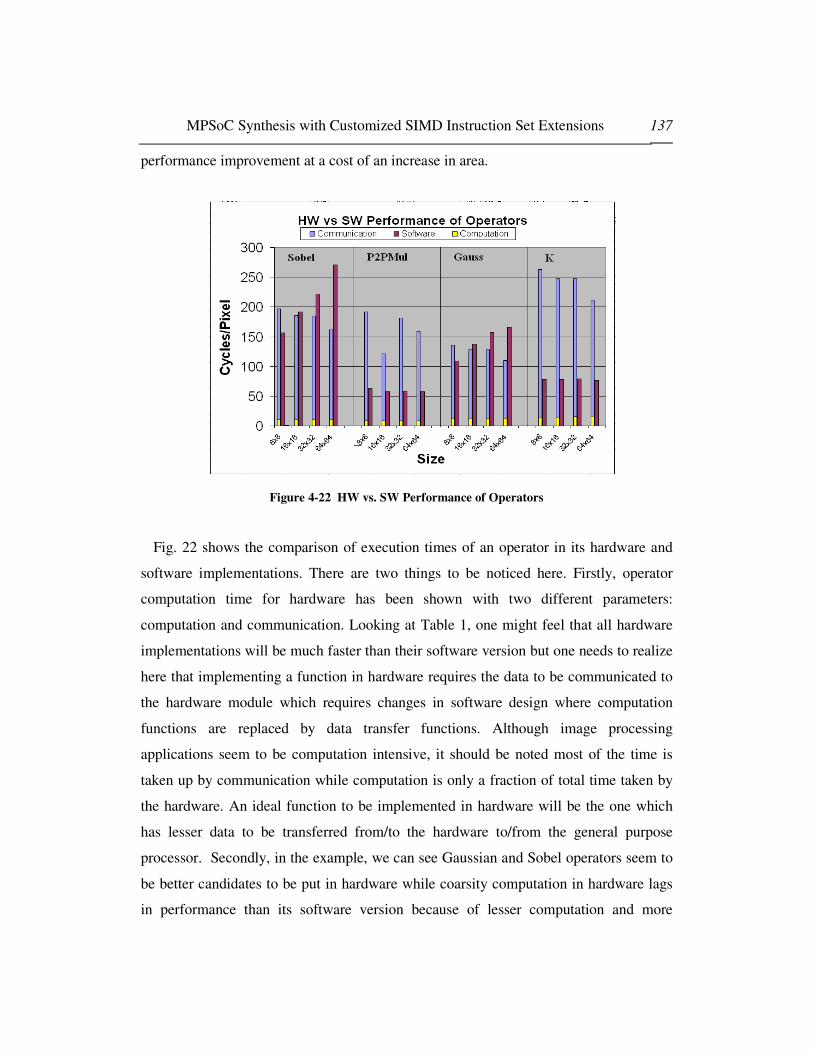
MPSoC Synthesis with Customized SIMD Instruction Set Extensions 137
performance improvement at a cost of an increase in area.
Figure 4-22 HW vs. SW Performance of Operators
Fig. 22 shows the comparison of execution times of an operator in its hardware and
software implementations. There are two things to be noticed here. Firstly, operator
computation time for hardware has been shown with two different parameters:
computation and communication. Looking at Table 1, one might feel that all hardware
implementations will be much faster than their software version but one needs to realize
here that implementing a function in hardware requires the data to be communicated to
the hardware module which requires changes in software design where computation
functions are replaced by data transfer functions. Although image processing
applications seem to be computation intensive, it should be noted most of the time is
taken up by communication while computation is only a fraction of total time taken by
the hardware. An ideal function to be implemented in hardware will be the one which
has lesser data to be transferred from/to the hardware to/from the general purpose
processor. Secondly, in the example, we can see Gaussian and Sobel operators seem to
be better candidates to be put in hardware while coarsity computation in hardware lags
in performance than its software version because of lesser computation and more

MPSoC Synthesis with Customized SIMD Instruction Set Extensions 138
communication requirements of the function.
Table 4-3 Various configurations and Speedups for Point of Interest Detection
Config.
No.
Hardware
Implement.
Time (cycle) Cycle/pix (cpp) Speedup Over
Software Version
1 Sobel 3726350 909.75 2.07
2 P2PMul 5419590 1323.14 1.42
3 Gauss 3490064 852.06 2.21
4 K = Coarsity
Comp.
4725762 1153.75 1.63
5 Sobel + P2PMul 4970836 1213.58 1.55
6 Sobel + K 4277108 1044.22 1.80
7 Sobel +
Gauss
3041510 742.56 2.53
8 Gauss + P2PMul 4734654 1155.92 1.63
9 Gauss+
K
4040826 986.52 1.91
10 Optimized
Software
4175000 1019.29 1.85
11 Original
Software Version
7717000 1884.03 1
After the performance comparison of operators in hardware and software, next step
was to generate the platform and perform the system level simulation for various
configurations. For our system level simulation, our general purpose processor
(PowerPC 405) was running at 333 MHz while it had 16K bytes of data and instruction
caches.
At first simulation run, we realized that due to data accesses, original software was
spending a lot time in memory access operations. We optimized the software which
resulted in an optimized version of the software. After that, we started exploring
HW/SW codesign options by generating various versions and getting the simulation

MPSoC Synthesis with Customized SIMD Instruction Set Extensions 139
results. Table 2 shows a few of the configurations generated and the CPU cycles taken
by the system during the simulation. A quick look at the results shows that taking into
consideration of hardware implementation cost, configuration 7 provides a good
speedup where we have implemented Gaussian and Gradient functions in the hardware.
Table 1 shows that adding these operators to hardware will result in a slight increase in
computation logic while a bit more increase in memory and at that cost a speedup of
more than 2.5 can be obtained.
Fig.7 graphically represents the Table 2. We can see that the configuration involving
Sobel and Gaussian operators gives significant speedups while configurations involving
point to point multiplication and coarsity computation (K) result in worse performance.
Based on these results, a system designer might choose configuration 7 for an optimal
solution. Or if he has strong area constraints, configuration 1 and 3 can be possible
solutions for co-designed system.
Figure 4-23 a) Platform configuration 7 (b) full HW/SW Design Space Exploration Results
When configuration 7 was chosen to be the suitable configuration for our system, next
step was the parameterization of the system. Although parameterization involves bus
width adjustment, arbitration scheme management and interrupt routine selection, for
the sake of simplicity we show the results for optimal sizes of caches. Fig. 5 shows the
results for various cache sizes and corresponding performance improvement. We can
see that cache results in significant performance improvements until 16K of data and
IBM
Embedded
PowerPC
(no FP)
Memory Sobel Gauss
CA

MPSoC Synthesis with Customized SIMD Instruction Set Extensions 140
instruction cache sizes.
But after that, the performance improvements with respect to cache size changes
reach a saturation point and there is almost no difference of performance for 16K and
64K caches in the system. Hence we choose 16K data and instruction caches sizes for
our final system.
Cache sizes vs Cycles/Pixel
742,5 742816
3876
0
1000
2000
3000
4000
5000
No Cache 4K 16K 64K
Cache sizes (Instruction and Data)
Cyc
les/
Pix
el
Figure 4-24 Various Cache Sizes and System Performance
This approach allowed us to alleviate the problem of selecting inadequate
microcontrollers for intelligent vehicle design such as those described Section II. This
process can be repeated with other applications in order to build a system based on
networked platforms.
Figure 4-25 Platforms networked through CAN bus
CAN Bus
MPSoC Synthesis with Customized SIMD Instruction Set Extensions 141
Lastly, we will mention the limitations of the methodology. It should be noticed that
we have chosen small image sizes for our system design. Although TLM level
simulation is much faster than RTL level simulations, it still takes a lot of time for
simulation of complex systems. Increasing the image sizes beyond 256x256 for the
given example makes it increasingly difficult for exploring the design space thoroughly
as it required multiple iteration of simulation for each configuration and one iteration
itself takes hours or even days to complete. For larger image sizes where simulation
time will dominate the system design time, RTL level system prototyping and real time
execution over hardware prototyping boards seems to be a better idea where although
system prototyping will take longer times but significant time savings can be made by
preferring real time execution over simulations. The approach of [51] can be used in this
context.
4.5.3 Extensions: Combining UML based System design flow with
SystemC TLM platform for intelligent vehicles Design
The work presented in this section so far described the potentials of SystemC TLM
platform based design for the system design of embedded applications through the
customization of microcontrollers. Clearly important benefits come from this approach
with the possibility to get access to implementation details (area, energy consumption)
without lowering the design abstraction details down to implementation. This key point
clearly contributes to the reduction of the design cycle and the ease of the design space
exploration. On the other hand several research projects have advocated the use of UML
based system design for real time embedded systems [30-33]. The Accord/UML is a
model-based methodology dedicated for the development of embedded real-time
applications [30]. The main objectives of the methodology are to specify and prototype
embedded real-time systems through three consistent and complementary models
describing structure, interaction and behavior. Examples of applications include smart
transducer integration in real time embedded systems [33].

MPSoC Synthesis with Customized SIMD Instruction Set Extensions 142
Figure 4-26 Accord/UML Design Methodology
One key step of the Accord/UML methodology is the model transformation from a
UML design model platform independent to a UML design model platform specific.
This is mainly accomplished through a transformation with a worst case execution time
(WCET) valuation. This PSM could be improved by iterating through a UML
performance analysis model which would again influence the transformation. This
performance analysis model could be conducted using SystemC TLM platform model
and include additional analysis with area and energy consumption as we did in previous
section the image processing chain. The objectives of the ProMARTE working group is
to define a UMLTM Profile for Modeling and Analysis of Real-Time and Embedded

MPSoC Synthesis with Customized SIMD Instruction Set Extensions 143
systems (MARTE) that answers to the RFP for MARTE [31]. These examples of UML
based design methodologies of embedded real time systems suggest that UML and
Platform SystemC TLM design methodologies may be combined for intelligent vehicles
design In this regard, the Autosar organization have released its UML profile v1.0.1 as
a metamodel to describe the system, software and hardware of an automobile [26]. This
profile is expected to be used as well for intelligent vehicles design. However
translation from UML/SysML to SystemC has only recently been tackled. Work has
been conducted on the description of executable platforms at the UML-level as well as
the translation of UML-based application descriptions to SystemC [46]. However, this
work is far from getting down to a SystemC level of the platform we used in this study.
In [44] they present a UML2.0 profile of SystemC language exploiting MDA
capabilities. No significant example of the methodologies is shown. In [42] a bi-
directional UML-SystemC translation tool called UMLSC is described. According to
the authors more work remains to be done to extend UML to make it better suited for
hardware specification and improve the translation tool. In [45] translation from UML
to SystemC for stream processing applications is presented. This work allows the
translation of a stream processor however not a full-fledged processor. It is an
implementation of the abstract model in UML 2.0. A very recent significant example of
translation is provided in [48] using network on chip. However, all the work mentioned
so far did not use: (1) SystemC TLM platform based design (2) area and energy
consumption of platform configurations.
We propose a UML/SysML to SystemC design flow methodology exclusively
targeting platforms. That is we are not interested to directly translate UML to hardware
level nor we are interested to translate UML to SystemC. In a SystemC TLM platform
modules have SystemC interface but can be written with C. So UML structural parts are
met with structural part of SystemC TLM platform while internal behavior of modules
is provided in C. This requires for area/energy consumption tradeoffs C based synthesis
and energy estimate tools such as [13]. Our proposed flow transforms UML to SystemC
TLM Platforms with design space exploration at SystemC TLM level for timing, area
and energy.
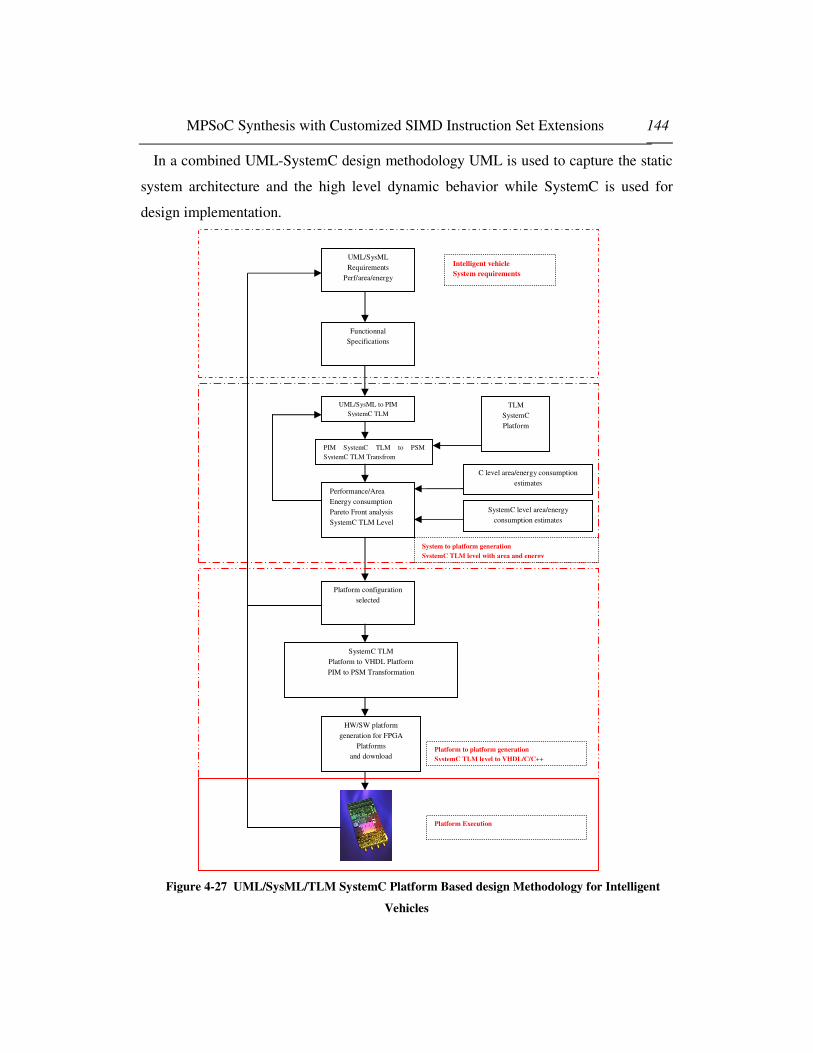
MPSoC Synthesis with Customized SIMD Instruction Set Extensions 144
In a combined UML-SystemC design methodology UML is used to capture the static
system architecture and the high level dynamic behavior while SystemC is used for
design implementation.
Figure 4-27 UML/SysML/TLM SystemC Platform Based design Methodology for Intelligent
Vehicles
UML/SysML
Requirements
Perf/area/energy
Functionnal
Specifications
UML/SysML to PIM
SystemC TLM
Performance/Area
Energy consumption
Pareto Front analysis
SystemC TLM Level
Platform configuration
selected
TLM
SystemC
Platform
C level area/energy consumption
estimates
SystemC level area/energy
consumption estimates
SystemC TLM
Platform to VHDL Platform
PIM to PSM Transformation
HW/SW platform
generation for FPGA
Platforms
and download
Intelligent vehicle
System requirements
System to platform generation
SystemC TLM level with area and energy
Platform to platform generation
SystemC TLM level to VHDL/C/C++
Platform Execution
PIM SystemC TLM to PSM
SystemC TLM Transfrom
MPSoC Synthesis with Customized SIMD Instruction Set Extensions 145
The transformation of the SystemC TLM to VHDL platform is straightforward and
will be described in a future publication [52]. The use of FPGA platforms allows faster
prototyping especially if one considers actual intelligent vehicle driving conditions [53,
54]. This overall design flow will be the focus of future work [55].
4.6 Conclusions
In this chapter, we have proposed a platform based SystemC TLM system level
design methodology for embedded applications. This methodology emphasizes on
components based software design and high level (TLM) modeling and simulation. Our
proposed design flow facilitates the process of system design by higher leveling
hardware modeling and behavioral synthesis of hardware modules. We have showed
that using the methodology, complex image processing applications can be synthesized
within very short time hence increasing the productivity and reducing overall time to
market for an electronic system. Our case study on intelligent vehicle systems shows the
usefulness of our approach.
Further work needs to be done to extend to raising the design methodology
abstraction level to combined UML/SysML/TLM SystemC Platform design flow.
REFERENCES
[4.1] Bucher, T.; Curio, C.; Edelbrunner, J.; Igel, C.; Kastrup, D.; Leefken, I.; Lorenz, G.; Steinhage, A.; von Seelen, W., Image processing and behavior planning for intelligent vehicles, Industrial Electronics, IEEE Transactions on Volume 50, Issue 1, Feb. 2003 Page(s):62 – 75
[4.2] Li; Jingyan Song; Fei-Yue Wang; Wolfgang Niehsen; Nan-Ning Zheng;, IVS 05: new developments and research trends for intelligent vehicles Intelligent Systems, IEEE [see also IEEE Intelligent Systems and Their Applications], Volume 20, Issue 4, July-Aug. 2005 Page(s):10 – 14
[4.3] McCall, J.C.; Trivedi, M.M., Video-based lane estimation and tracking for driver assistance: survey, system, and evaluation, Intelligent Transportation Systems, IEEE Transactions on Volume 7, Issue 1, March 2006 Page(s):20 – 37
[4.4] Girard, A.P.; Spry, S.; Hedrick, J.K.;, Intelligent cruise control applications: real-time embedded hybrid control software, Robotics & Automation Magazine, IEEE Volume 12, Issue 1, March 2005 Page(s):22 – 28
[4.5] van der Mark, W.; Gavrila, D.M.;, Real-time Dense Stereo for intelligent vehicles Intelligent Transportation Systems, IEEE Transactions on Volume 7, Issue 1, March 2006 Page(s):38 – 50
MPSoC Synthesis with Customized SIMD Instruction Set Extensions 146
[4.6] Muller-Glaser, K.D.; Frick, G.; Sax, E.; Kuhl, M., Multiparadigm modeling in embedded systems design Muller-Glaser, K.D.; Frick, G.; Sax, E.; Kuhl, M., Control Systems Technology, IEEE Transactions on Volume 12, Issue 2, March 2004 Page(s):279 – 292
[4.7] Freescale Semiconductors http://www.freescale.com/ [4.8] IBM CoreConnect www.ibm.com [4.9] IEEE 1666 Standard SystemC Language Reference Manual www.systemc.org http://standards.ieee.org/getieee/1666/download/1666-2005.pdf [4.10] Synopsys. Behavioral Compiler User Guide Version 2003.10, 2003 [4.11] Agility : http://www.celoxica.com/products/agility/default.asp [4.12] S Chtourou, O Hammami, “SystemC Space Exploration of Behavioral Synthesis Options on
Area, Performance and Power consumption” ”, IEEE International Conference on Microelectronics (ICM Islamabad) 2005.
[4.13] Orinoco Dale http://www.chipvision.com/company/index.php [4.14] IBM PEK v1.0 http://www-128.ibm.com/developerworks/power/library/pa-pek/ [4.15] “RiscWatch Debuggers User Guide”, Fifteenth Edition, IBM Publication Number: 13H6964
000011, May 2003 [4.16] OSCI SystemC Transaction-level Modeling Working Group (TLMWG) http://www.systemc.org/web/sitedocs/technical_working_groups.html [4.17] Frank Ghenassia (Editor) Transaction-Level Modeling with Systemc: TLM Concepts and
Applications for Embedded Systems, ISBN: 0387262326, Springer; 1 edition (January 11, 2006) [4.18] L. Cai, and D. Gajski, "Transaction Level Modeling: an overview", in IEEE/ACM/IFIP
International Conference on Hardware/Software codesign and System Synthesis, pp.19-24, 2003.
[4.19] N. Calazans, E. Moreno, F. Hessel, V. Rosa, F. Moraes, E. Carara, “From VHDL register transfer level to SystemC transaction level modeling: a comparative case study”, Proceedings. 16th Symposium on Integrated Circuits and Systems Design, 2003. pp.355 – 360, 2003.
[4.20] O. Capdevielle, P. Dalle, Image processing chain construction by interactive goal specification, First IEEE ICIP, Austin, Texas (USA), pp. 816-820, November 1994.
[4.21] Yazid Abchiche, Patrice Dalle et Yohann Magnien ,“Adaptative Concept Building by Image Processing Entity Structuration”, Institut de Recherche en Informatique de Toulouse IRIT - Université Paul Sabatier
[4.22] S.A. Teukolsky, William T. Vetterling and W.H Press, “Numerical recipes: The art of scientific computing”, (Cambridge University Press, Cambridge), 1989
[4.23] Tie Liu; Nanning Zheng; Hong Cheng; Zhengbei Xing, Multi-DSP based intelligent vehicle vision system and software & hardware co-realization, Intelligent Control and Automation, 2004. WCICA 2004. Fifth World Congress on Volume 6, 15-19 June 2004 Page(s):5248 - 5252 Vol.6
[4.24] T.Pop, P.Pop, P.Eles and Z.Peng, Bus Access Optimization for FlexRay-based Distributed Embedded Systems, in DATE 20007, April 16-20, 2007, Nice, France.
[4.25] W.Zheng, M.Di Natale, A. Sangiovanni Vincentelli, C. Pinello and P.Giusto, Synthesis of Task and Message Activation Models in Real-time Distributed Automotive Systems, in DATE 20007, April 16-20, 2007, Nice, France.
[4.26] UML Profile for Autosar v1.0.1 http://www.autosar.org/ [4.27] MDA Guide Version 1.0.1 June 2003, OMG [4.28] Systems Modeling Langage (SysML) Specifications, OMG Document : ad/2006-03-1 Version
1.0 , April 2006 [4.29] France, R.B.; Ghosh, S.; Dinh-Trong, T.; Solberg, A., Model-driven development using UML
2.0: promises and pitfalls, Computer, Volume 39, Issue 2, Feb. 2006 Page(s):59 – 66 [4.30] Accord/UML http://www-list.cea.fr/labos/fr/LLSP/accord_uml/AccordUML_presentation.htm [4.31] ProMARTE www.promarte.org [4.32] Protes project www.carroll-research.org [4.33] Jouvray, C.; Gerard, S.; Terrier, F.; Bouaziz, S.; Reynaud, R.;, UML methodology for smart
transducer integration in real-time embedded systems, Intelligent Vehicles Symposium, 2005. Proceedings. IEEE 6-8 June 2005 Page(s):688 – 693

MPSoC Synthesis with Customized SIMD Instruction Set Extensions 147
[4.34] Gerard, S.; Mraidha, C.; Terrier, F.; Baudry, B., A UML-based concept for high concurrency: the real-time object Object-Oriented Real-Time Distributed Computing, 2004. Proceedings. Seventh IEEE International Symposium on 2004 Page(s):64 – 67
[4.35] Saiedian, H.; Raghuraman, S.Using UML-based rate monotonic analysis to predict schedulability, Computer Volume 37, Issue 10, Oct. 2004 Page(s):56 – 63
[4.36] Pao-Ann Hsiung; Shang-Wei Lin; Chih-Hao Tseng; Trong-Yen Lee; Jin-Ming, Fu; Win-Bin See, VERTAF: an application framework for the design and verification of embedded real-time software, Software Engineering, IEEE Transactions on Volume 30, Issue 10, Oct. 2004 Page(s):656 – 674
[4.37] IEEE standard test methods for use in the evaluation of message communications between intelligent electronic devices in an integrated substation protection, control and data acquisition system IEEE Std C37.115-2003 2004
[4.38] Bjerkander, M.; Kobryn, C., Architecting systems with UML 2.0, Software, IEEE , Volume 20, Issue 4, July-Aug. 2003 Page(s):57 – 61
[4.39] Dimitrov, E.; Schmietendorf, A.; Dumhe, R.;, UML-based performance engineering possibilities and techniques, Software, IEEE Volume 19, Issue 1, Jan.-Feb. 2002 Page(s):74 – 83
[4.40] Riccobene, E.; Scandurra, P.; Rosti, A.; Bocchio, S., A Model-driven Design Environment for Embedded Systems, Design Automation Conference, 2006 43rd ACM/IEEE 24-28 July 2006 Page(s):915 – 918
[4.41] Dekeyser, J.; Boulet, P.; Marquet, P.; Meftali, S.;, Model driven engineering for SoC co-design, IEEE-NEWCAS Conference, 2005. The 3rd International 19-22 June 2005 Page(s):21 – 25
[4.42] Chen Xi; Lu Jian Hua; Zhou ZuCheng; Shang YaoHui;, Modeling SystemC design in UML and automatic code generation, Design Automation Conference, 2005. Proceedings of the ASP-DAC 2005. Asia and South Pacific Volume 2, 18-21 Jan. 2005 Page(s):932 - 935 Vol. 2
[4.43] Kreku, J.; Etelapera, M.; Soininen, J.-P.;, Exploitation of UML 2.0—Based Platform Service Model and SystemC Workload Simulation in MPEG-4 Partitioning System-on-Chip, 2005. Proceedings. 2005 International Symposium on 15-17 Nov. 2005 Page(s):167 – 170
[4.44] Riccobene, E.; Scandurra, P.; Rosti, A.; Bocchio, S.;, A SoC design methodology involving a UML 2.0 profile for SystemC Design, Automation and Test in Europe, 2005. Proceedings 2005 Page(s):704 - 709 Vol. 2
[4.45] Yongxin Zhu; Zhenxin Sun; Weng-Fai Wong; Maxiaguine, A.;, Using UML 2.0 for system level design of real time SoC platforms for stream processing, Embedded and Real-Time Computing Systems and Applications, 2005, Proceedings. 11th IEEE International Conference on 17-19 Aug. 2005 Page(s):154 – 159
[4.46] Nguyen, K.D.; Zhenxin Sun; Thiagarajan, P.S.; Weng-Fai Wong, Model-driven SoC design via executable UML to SystemC Real-Time Systems Symposium, 2004. Proceedings. 25th IEEE International 5-8 Dec. 2004 Page(s):459 – 468
[4.47] Schulz-Key, C.; Winterholer, M.; Schweizer, T.; Kuhn, T.; Rosentiel, W., Object-oriented modeling and synthesis of SystemC specifications Design Automation Conference, 2004. Proceedings of the ASP-DAC 2004. Asia and South Pacific 27-30 Jan. 2004 Page(s):238 – 243
[4.48] E.Riccobene, P.Scandurra, A.Rosti and S.Bocchio, A Model-driven Design Environment for Embedded Systems, DAC 2006, July 24-28 2006, San Francisco, CA.
[4.49] M.Krause, O.Bringmann, A.Hergenhan, G.Tabanoglu and W.Rosenstiel, Timing Simulation of Interconnected AUTOSAR Software-Components, in DATE 20007, April 16-20, 2007, Nice, France.
[4.50] P.Popp, M.Di Natale, P.Giusto, S.Kanajan and C.Pinello, Towards a Methodology for the Quantitative Evaluation of Automotive Architectures, in DATE 20007, April 16-20, 2007, Nice, France.
[4.51] R. Ben Mouhoub and O. Hammami, “MOCDEX: Multiprocessor on Chip Multiobjective Design Space Exploration with Direct Execution,” EURASIP Journal on Embedded Systems, vol. 2006, Article ID 54074, 14 pages, 2006.
[4.52] O.Hammami and Z.Wang, Automatic PIM to PSM Translation, submitted for publication.

MPSoC Synthesis with Customized SIMD Instruction Set Extensions 148
[4.53] S.Saponara, E.Petri, M.Tonarelli, I; Del Corona, L.Fanucci, FPGA-based Networking Systems for High Data-Rate and Reliable In-vehicle Communications, in DATE 20007, April 16-20, 2007, Nice, France.
[4.54] C.Claus, J.Zeppenfeld, F.Muller and W.Stechele, Using Partial Run Time Reconfigurable Hardware to Accelerate Video Processing in Driver Assistance Systems, in DATE 20007, April 16-20, 2007, Nice, France.
[4.55] O.Hammami, Automatic Design Space Exploration of Automotive Electronics: The case of AUTOSAR, submitted for publication.
[4.56] Scott Hamilton, “Intel Research Extends Moore's Law”, IEEE Computer Magazine,Vol. 36, No.
1, pp. 31-40, January 2003
[4.57] “A Power Estimation Methodology for SystemC Transaction Level Models”,
[4.58] G. Qu, N. Kawabe, K, Usame, M. Potkonjak, Function-level power estimation methodology for
microprocessors, Proceedings of the 37th DAC, 2000
[4.59] R. Bergamaschi, Y.W. Jiang, “State-based power analysis for systems-onchip”, Proceedings of
the 40th Design Automation Conference, 2003.
[4.60] L. Zhong, S. Ravi, A. Raghunathan, N. K. Jha.”Power Estimation for Cycle- Accurate
Functional Descriptions of Hardware”, ICCAD 2004.
[4.61] Nabel, W.,”Predictable design of low power systems by pre-implementation estimation and
optimization”, DATE 2004, Volume , Issue , 27-30 Jan. 2004 Page(s): 12 - 17
[4.62] International Technology Roadmap for Semiconductors: Design, 2005
[4.63] Coware Convergensc: www.cadence.com/whitepapers/CDNCoWare_WPfnl.pdf
[4.64] ARM SoC Designer: www.arm.com/products/DevTools/MaxSim.html
[4.65] Synopsys system studio: www.synopsys.com/products/cocentric_studio/cocentric_studio.html
[4.66] www-306.ibm.com/chips/techlib/techlib.nsf/products/PowerPC_750FX_Evaluation_Kit
[4.67] CoreConnect™ bus architecture, IBM Microelectronics Whitepaper, 1999 [4.68] K. S. Vallerio and N. K. Jha, “Task graph extraction for embedded system synthesis,” in Proc.
Int. Conf. VLSI Design, New Delhi, India, Jan. 2003, pp. 480–486. [4.69] S. Chtourou, O. Hammami, "SystemC space exploration of behavioral synthesis options on area,
performance and power consumption", Proceedings of International Conference on Microelectronics, De. 2005
[4.70] conomakos, G.; Oikonomakos, P.; Panagopoulos, I.; Poulakis, I.; Papakonstantinou, G.,"Behavioral Synthesis with SystemC", Proceedings of DATE 2001, Page 839, 2001
[4.71] Vikram Singh Saun; Preeti Ranjan Panda, "Extracting exact finite state machines from behavioral SystemC descriptions", Proceedings of International Conference on VLSI Design, Page280-285, 2005
[4.72] Eike Grimpe ,Frank Oppenheimer ,"Extending the SystemC synthesis subset by object-oriented features", Proceedings of ISSS+CODES 2003, Page25-30, 2003
MPSoC Synthesis with Customized SIMD Instruction Set Extensions 149
5. MPSoC and NoC Synthesis with Custom SIMD
Extensions
Work presented in chapter three and four addresses the issue of custom instruction
set synthesis and system level design in two separate methodologies. Instruction set
synthesis methodologies exploit fine grained instruction level and data level parallelism
while system level design is more related to deal with thread level and task level coarse
grained parallelism. This chapter combines the work done in chapter three and four to
propose an integrated methodology that allows the designers to improve system
performance by using both levels of parallelism inherent in the system.

MPSoC Synthesis with Customized SIMD Instruction Set Extensions 150
5.1 Introduction
To meet the high computational requirements of emerging embedded applications,
system designers are increasingly shifting their attention to application specific
multiprocessor system on chip (MPSoC) designs. Modern MPSoCs include several
processing elements including general purpose processors, digital signal processors,
coprocessors and custom hardware IP components to perform various computations.
Because of heterogeneity inherent in application specific MPSoCs, communication
patterns between these processing elements are also becoming more and more complex.
As a result, legacy bus-based communication architectures have been unable to cope
with the increasing complexity for on-chip communication because of their poor
scalability, both in terms of performance and power efficiency. Therefore, structured
Network on Chip (NoC) based communication architecture has replaced the custom
(global) wires and shared bus based architectures. As the complexity of With the advent
multimedia applications increases further, MPSoC and NoC designs are expected to
become even more complex involving several cores for dealing with communication
and computation aspects of application design which will require new design
methodologies addressing the key issues of complexity, productivity and silicon
efficiency [1].
A different approach for achieving better performance from limited resources has
been extensible instruction set synthesis. In this approach, a general purpose processor
is extended with specialized instructions based on the patterns found in data flow graph
of the application. As a result, complex sequence of instructions occurring more
frequently in a program are replaced by special instructions which results in significant
speed up of the processor performance with little increase in area and energy
requirement of the extended processor.
Main difference between above mentioned approaches is that MPSoC synthesis
exploits coarse grained task level parallelism inherent in an application while extensible
processor synthesis methodologies target its fine grained data level parallelism
properties. Till now, most of the traditional design methodologies address only one level
of parallelism for performance improvement. Almost no work has been done that

MPSoC Synthesis with Customized SIMD Instruction Set Extensions 151
addresses fine grained and coarse grained parallelism in an integrated methodology
involving extensible processor synthesis at the same time as MPSoC synthesis. In this
chapter, we propose a system level design methodology that combines both levels of
parallelism concurrently in an integrated environment hence introducing a design flow
for MPSoC synthesis where each general purpose processor is extended with suitable
extended instructions concurrently with task mapping/.scheduling tasks. Our
experiences emphasize that before increasing the complexity of MPSoC and NoC to
meet the performance constraints of an application, an effort should be made to use fine
grained data level parallelism at individual processing elements using instruction set
extensions. Our results show that our approach significantly reduces the complexity of
an MPSoC and its underlying NoC without significant compromises on the performance
of the application.
Rest of the chapter is organized as follows: Section II briefly describes motivation of
our work explaining different types of parallelism inherent in applications and
architectures. Section III presents the related work. Section IV explains main issues
faced in the problem and Section V explains the general design flow of our
methodology followed by experimental environment and results in section VI and VII.
Section VIII concludes the chapter and hints at the possible future works.
5.2 Motivation
Choice of exploiting suitable type of parallelism for future embedded systems has
been a topic of special interest for research community in industry and academia. Fig.1
briefly classifies the various types of parallelism. While superscalar computing and
pipelining techniques has been excessively being used in high performance general
purpose processor architectures, industry has started seeing saturation in the
performance results with the increase in complexity of pipelines and superscalar
architectures. Performance of superscalar architectures depends on instruction level
parallelism inherent in the program and it is now a well known fact [2] that most of the
programs have lesser degree of instruction level parallelism which severely affects the

MPSoC Synthesis with Customized SIMD Instruction Set Extensions 152
efficiency of superscalar architectures leaving several execution units under-utilized.
Similarly, increasing the pipeline depth is a trivial task because of long restart penalties
on changes in control flow, requiring complex mechanisms such as branch predictors
and speculative execution. VLIW machines face the same problem as of superscalar
machines with additional compiler issues involving prediction, code compression,
rotating registers etc. Because of the bottlenecks faced in superscalar, pipelining and
VLIW architectures, industry has been looking for suitable alternatives and a lot of
interest has been seen in vector/SIMD, multiprocessing and multithreading techniques.
Figure 5-1 Classification of parallelism in Embedded Systems
Most of the high performance applications in modern embedded systems i.e. multimedia
and DSP applications possess higher degree of fine grained data level parallelism,
vector architectures especially SIMD instruction set extensions have evolved to be
preferable mode of fine grained parallelism exploitation. At the same time, embedded
industry has opted for coarse grained parallelism for on-chip multiprocessor
architectures because of time to market and productivity constraints. In last few years,
several system level design methodologies have been proposed for both MPSoC
synthesis and extensible instruction set synthesis. But unfortunately, almost all of the
synthesis methodologies restrict themselves to one level of parallelism. In our opinion,
restricting the design methodology to coarse grained level of parallelism unnecessarily
complicates the MPSoC architecture in the case of MPSoC synthesis. On the other
hand, emphasizing on fine grained data parallelism only using extensible instruction set
synthesis sometimes doesn't prove enough for performance requirements. There is a

MPSoC Synthesis with Customized SIMD Instruction Set Extensions 153
need to have system level MPSoC design methodologies that address both level of
parallelism at the same time for getting maximum benefit out of application's inherent
parallel properties. In this chapter, we propose a methodology for MPSoC synthesis
along with custom instruction set generation that exploits fine grained and coarse
grained parallelism at the same time. We show that by integrating custom extensible
instructions for tasks mapped over a processor, we can reduce the network complexity
of the system to obtain almost the same performance that could be achieved with
complex network on chip involving higher number of cores.
5.3 Related Work
Our work in this chapter combines two different but closely related domains in system
level synthesis. Although a lot of work has been done in both domains individually, a
very little work has been done that combines both domains together. A brief overview
of the work done in both domains is given below.
A. Extensible Processor Synthesis
Application Specific Instruction Processor (ASIP) synthesis problem been studied for
many years. Keutzer et al. have presented an overview of the latest trends in ASIP
design in [3]. Instruction set synthesis involves instruction selection and instruction
matching mechanisms as well as microarchitectural enhancement in extensible
processors. A methodology to synthesize custom instructions together with
microarchitecture is discussed in [4] while [5], [6] and [7] target ASIP synthesis
performance using ratargetable compiler for given hardware descriptions.
A lot of research has been done on synthesizing extensible instruction sets to improve
the performance of a base processor having a basic instruction set. Kucukcakar
described a methodology to add custom instructions and modify the ASIP architecture
[9]. Heuristic base approach has been used to select custom instructions under a limited
encoding space constraint in [11]. In [12] and [13], an automatic method has been

MPSoC Synthesis with Customized SIMD Instruction Set Extensions 154
proposed to generate custom instructions using operation patterns, and select the
instruction under an area budget. Cheung et al. proposed techniques for custom-
instruction selection, and mapping complex application code to predesigned custom
instructions in [14] and [15]. An interesting work proposed by Goodwin and Petkov
emphasizes on the techniques to generate custom instructions by identifying very long
instruction word (VLIW)-style operations, vectorized operations, and fused operations
in [21]. Several approaches for custom-instruction generation are based on identifying
data-flow subgraphs [16], [17], and symbolic algebra [18]. Biswas and Dutt presented a
heuristic to synthesize complex instructions for heterogeneous-connectivity based DSPs
in [19], and techniques to include local memories in custom instructions in [20]. Choi
et al. have seen the problem of generating complex instructions from primitive ones as a
modified subsetting problem in [10]. Work done in [8] also uses the subsetting problem
to show that ASIP's energy consumption is significantly reduced if basic instruction set
is chosen from a more general processor such as DSP. Technique for synthesis of
individual processors in this chapter is based on work done in [22]. This work targets
data intensive applications and uses a subset of SIMD instruction extensions to generate
an ASIP processor. As a result, ASIP design times are significantly reduced without
compromising on the performance and area constraints. One practical side, SIMD
standards have evolved and matured now hence ASIP designers have access to suitable
development environments, compilers, specialized algorithms etc. which allows
designers to address their efforts to ASIP design instead of concentrating on primitive
and non-related issues resulting is better productivity which can be suitable to be used in
an integrated methodology for MPSoC synthesis.
B. MPSoC and NoC Synthesis
A lot of work has been done on MPSoC and NoC synthesis. MPSoC synthesis
problem can be roughly divided into two problems: communication and computation
architecture synthesis. Communication architecture can be bus-based architectures on
which significant amount of work has been done. In [23], a bus synthesis tool has been
proposed to synthesize bus based communication architecture for MPSoC system for

MPSoC Synthesis with Customized SIMD Instruction Set Extensions 155
various types of busses. De Micheli has presented a crossbar synthesis methodology in
[24] while Nikil Dutt et al. [25] have recently proposed an automated approach for
synthesizing a bus matrix communication architecture which satisfies the performance
constraints in the design while minimizing wire congestion in the matrix. A lot of
literature is available on Network on chip based communication architecture [26] [27]
[28] [29] synthesis which are claimed to be alternative to existing bus based
architectures for future MPSoC systems involving complex communication patterns. A
survey of existing network on chip design methodologies has been proposed in [30]
while existing problems and challenges are described in [31]. Various methodologies
on NoC synthesis have been proposed in [32]-[41] addressing synthesis of regular and
irregular NoC structures. Heuristics based approach has been used in [34] to solve the
constraint driven NoC synthesis problem where constraints have been clustered to
reduce the overall number of constraints and then quadratic programming approach is
used to solve NoC synthesis problem under clustered constraints. An algorithm for
mapping a task graph on a NoC is proposed in [35] to minimize the communication
energy. NoC customization techniques for application specific MPSoC architectures are
discussed in detail in [36], [37], [38], and [39]. A platform for design space exploration
using heuristics and simulated annealing, power constrained network partitioning and
physical placing of network blocks is introduced in [40]. Issues related to physical
layout generation for optimized performance are discussed in [41]. Although all of
these proposed methodologies address some important aspect of NoC and MPSoC
synthesis, none of the work addresses the issue of processor micro-architecture
generation simultaneously along with MPSoC and NoC design space exploration.
Customizable soft cores provide a way for system designers to parameterize the
processor architecture concurrently with MPSoC synthesis. Work done in [42]-[45]
addresses the problem of soft core customization for MPSoC synthesis however
Parameterized soft cores represent a different problem from that of developing custom
datapath units and accompanying custom instructions, as done in application-specific
instruction-set processors (ASIPs) due to the “on/off” (or limited number of) values of
the parameters.

MPSoC Synthesis with Customized SIMD Instruction Set Extensions 156
A more recent work done by N.K Jha et al. [46] is probably closest to our work as it
addresses the issue of extensible processor synthesis in an MPSoC environment.
However their methodology is restricted to shared memory architectures and their target
platforms don't involve NoC based communication architectures. Moreover, their
synthesized systems don't involve coprocessor synthesis which proves to be more
efficient in several cases than the custom instruction extensions. On the other hand, our
methodology addresses the issue of custom hardware generation and involves the
performance comparison of custom hardware accelerators with extended instruction set
during design space exploration. We also study the impact of custom SIMD instruction
generation on communication architecture (network on chip) simplification which,
according to best of our knowledge, has not been studied so far.
5.4 Problem Overview
There are various concerns that should be addressed in an integrated methodology
for extensible instruction set generation with MPSoC synthesis. Two most important
issues are explained below.
Firstly, problem of MPSoC synthesis and extensible processor synthesis are very
tough even if they are taken as two separate problems. MPSoC synthesis problem
includes sub-problems of communication and computation architecture synthesis which
can be further decomposed as partitioning, allocation, mapping and scheduling
problems if HW/SW co-design is also considered part of the problem. Similarly,
extensible instruction set synthesis involves sub-problems of instruction set selection
and instructions matching which themselves are high complexity problems. So
combining both of the problems together as per traditional design flows complicates the
problem to unacceptable limits. General problem of combined MPSoC synthesis with
extensible instruction synthesis has been shown in Fig 2. As shown, a task graph is
mapped over processing elements on a NoC architecture where edges represent the
communication between various nodes. Now each task itself shows a degree of fine
grained data parallelism which can be exploited using extensible instruction set

MPSoC Synthesis with Customized SIMD Instruction Set Extensions 157
extensions. So according to the mapping decision taken on MPSoC, each processor
should be extended with custom instructions to achieve better performance at individual
nodes. But as mentioned above, the solution to the problem of combined synthesis is
very complex and because of productivity constraints, there needs to be a better
methodology that brings up a good balance between optimal results and simplification
of approach to achieve better productivity.
Extensible Instruction Synthesis for T4
MPY
XOR LD
XOR
SHR
XOR
MOVAND CUSTOM
General
PurposeProcessor
CustomHardware
LD
XOR SHR
Mapping of Tasks on an MPSoC Involving NoC
Figure 5-2 Integrating Extensible Instructions with MPSoC Synthesis using Traditional Design
Flows
Secondly, integration of both methodologies exposes new relationships between
various parameters. For example, mapping decisions strongly effect the extended
instruction set hence the architecture of extended processor. This gives rise to many
area/performance trade offs at each node in MPSoC. Task mapping decisions also
affects the amount and patterns of communication between various processors in a NoC.
This situation points out to the fact that task mapping, processor customization and
network on chip configuration are inter-related problems. As another example,
performance of one node can increase so much after extensible processor generation
that the mapping decisions might become sub-optimal requiring a newer mapping to
balance the workload on various nodes in network on chip and when new re-mapping is

MPSoC Synthesis with Customized SIMD Instruction Set Extensions 158
performed, instruction set extensions for each node need to be re-generated resulting in
iterative loops of several mappings and extended processor generation. Hence at system
level, it is important to come up with an exploration algorithm that can address these
problems simultaneously reaching to an optimal solution with least numbers of
iterations possible.
Our methodology addresses the both abovementioned issues. To reduce the
complexity of problem, we simplify the instruction set problem by introducing a new
flow for customizable SIMD synthesis that eliminates the instruction set selection and
instruction matching problems. Our simplified design flow assures integration of both
problems dealing with inter-related parameters in a suitable manner. More details on our
design flow are explained in next section.
5.5 Design Flow of Proposed Methodology
In this section, we describe our methodology for heterogeneous application-specific
multiprocessor synthesis with custom SIMD extensions. The design flow is shown in
Fig.3. Our design process starts with the development of application. For each
application, either its task graph can be extracted by profiling or alternatively an
application can be developed as a chain of various tasks where each task represents a
specific operation of significant size. We have done our experiments over image
processing application hence each of our tasks represents an image processing operator
and whole application can be seen as a chain of image processing operators. In this
image processing chain, each image processing operator represents a node with certain
input and output images while communication between operators is represented by
edges between the nodes. The problem of MPSoC synthesis with custom instruction set
extensions can be seen as a mapping and scheduling of tasks on a multiprocessor
platform such that:
4. Overall execution time for the application is reduced and performance
constraints are met.

MPSoC Synthesis with Customized SIMD Instruction Set Extensions 159
5. Each processor is suitably extended with custom instructions according to the
tasks mapped over it to reduce the area overheads.
6. Network on chip architecture is simplified because of performance
improvements at individual nodes caused by custom instruction insertion with
general purpose processor.
Figure 5-3 MPSoC Design Methodology for SIMD extended processor with an underlying NoC

MPSoC Synthesis with Customized SIMD Instruction Set Extensions 160
Other than application development, we also design a reference platform in the
beginning of design step. Selection of a reference platform depends on the complexity
of the application and real time performance constraints and it is done by the system
designer intuitively. However, it should be noted that our algorithm for multiprocessor
synthesis is iterative in nature where reference platform is updated in each high level
iteration hence optimal results are guaranteed even if system designer chooses for a sub
optimal platform in the beginning process although it should be noted that bad reference
platform selection will prolong the synthesis process because of large number of
iterations involved.
5.5.1 Mapping Problem
After reference platform is developed, various tasks of the applications are mapped
on the network. As mentioned in previous section, mapping problem affects both the
aspects of system design being addressed: extended processor architecture and network
traffic. For example, if two consecutive tasks T1 and T2 have large amount of data to be
transferred between each other, the mapping decision should try to either map both tasks
on a same computation element or it should be mapped over two computational
elements which are neighbours in the network so that data doesn't need to traverse the
whole network to reach the required processing element. Similarly, tasks containing
similar instructions should be mapped on a processor extended with custom SIMD
instructions to reduce the area overhead of extensible instruction implementation.
In our algorithm, our reference platform doesn't include SIMD extended processors
hence initially mapping is done primarily to effectively distribute the tasks over the
heterogeneous MPSoC aimed at reducing computation times on processing elements
and communication times on underlying NoC. After mapping is done for the given
application and platform, simulations are performed to get performance results for given
configuration. On the other hand, area and energy consumption results are obtained by
synthesizing the individual tasks using behavioral synthesis tools. We are using
Celoxica's agility compiler tool or this purpose however any behavioral synthesis tool or
SystemC can be used to get energy and area estimates for the platform.

MPSoC Synthesis with Customized SIMD Instruction Set Extensions 161
5.5.2 Custom SIMD Instruction Set Extended Processor Generation
As mentioned above, Instruction set synthesis problem generally involves two sub
problems: instruction set selection and instruction matching. We simplify the problem
of instruction set selection by taking whole SIMD standard as the selected instruction
set. On the other hand, instruction matching is performed either by compiler which
vectorizes each task automatically or by software programmer who writes the efficient
vectorized code manually. Our main idea is to start from a full SIMD unit
implementation connected in parallel to the main pipeline of a general purpose
processor and then removing the hardware related to the instructions that have not been
used for the tasks mapped over the processor. The decision for the instructions to be
removed depends on the profiling results which give type and frequency of instructions
used for a certain program. As a result, our customized processor consists only of those
instructions that are actually needed by the program resulting in reduced area and power
consumption of the extended processor. In our complete flow, we also define the
concept of equivalent class to eliminate those vector instructions which take more area
but don't provide enough speed up because of their low frequency in the program. These
low frequency instructions are eliminated by replacing them with one or more scalar or
vector instruction performing the same functionality. More details on equivalence class
and instruction set selection are out of scope of this chapter however interested readers
can consult [22] to see more on the topic.
5.5.3 Network Simplification
Our iterative exploration algorithm can reconfigure the reference platform after
every high level iteration. If performance constraints are not met, additional nodes are
added in the NoC and process of SIMD customization is repeated again to observe the
performance improvements. However, if performance constraints are met then iterative
algorithm tries to reduce the network complexity by removing some nodes and shifting

MPSoC Synthesis with Customized SIMD Instruction Set Extensions 162
the functionality implemented over these nodes to SIMD tasks implemented over
extensible processor.
Once performance constraints are met and network complexity is sufficiently
reduced, configuration is finalized and designer can proceed to implementation process
of the system at lower layers of abstraction.
5.6 Experimental Setup
Our experimental setup uses various tools for setting up a platform to verify the
effectiveness of the design flow presented in last section. As mentioned in chapter 3, we
have used Xilinx based Virtex-4 FPGAs to synthesize AltiVec instruction set. EDK and
ISE were used for developing and synthesizing the platforms for individual nodes in the
NoC. For NoC implementation, we use systemC based OCCN libraries developed at
STMicroelectronics for fast way of NoC verification. For verification of complete
systems involving extended processors with network on chip architectures, we have
extended ppc750sim [54] which is a PowerPC 750 (G3) simulator written in SystemC
which achieves a 10% inaccuracy on SPEC CINT 2000 compared to a real PowerPC
750 microprocessor. High level architecture of PowerPC 750 is shown in Fig 4. It is to
be noted that PowerPC 750 doesn't contain AltiVec instruction set extension so we have
written AltiVec extension for the PowerPC consisting of approximately 8000 lines of
code and added them in parallel to the main pipeline of the processor as shown by the
two left most boxes in Execution stage of pipeline. Although PowerPC750 uses out of
order instruction execution for its main pipeline used for execution of general purpose
instruction, our part of pipeline that starts after dispatch unit and executes the
instructions uses in-order execution of SIMD instructions for simplicity.

MPSoC Synthesis with Customized SIMD Instruction Set Extensions 163
Figure 5-4 PowerPC 750 extended with AltiVec Instruction Set
Once micro-architecture of the processor is extended with custom SIMD instruction,
a top level file has been created that can initialize multiple copies of processors. Using
systemC, network interfaces has been written and network libraries provided by OCCN
[55] has been used to implement network architecture between the processor. OCCN
libraries provides router, packet data unit (PDU), queues, channels and statistics classes
and other basic elements required to implement and analyze a communication
architecture. In case of use of custom hardware IPs, we have used systemC behavioral
level description to write the hardware elements and they have been synthesized using
Celoxica agility compiler [56] to get estimated area of each accelerator. Using all
these elements, it becomes possible to implement a complex heterogeneous
multiprocessor system including a network on chip in very short development time.
During our experimentation, we manually implement the top level systemC files to
initialize and connect all these components for various configurations tested during our
design space exploration process. Fig. 5 shows the block diagram of a 2x2 network on
chip based on mesh topology built using our experiment environment. Queues between
routers and computation elements have been shown using arrow marks describing the
direction of communication while computation elements are connected to network
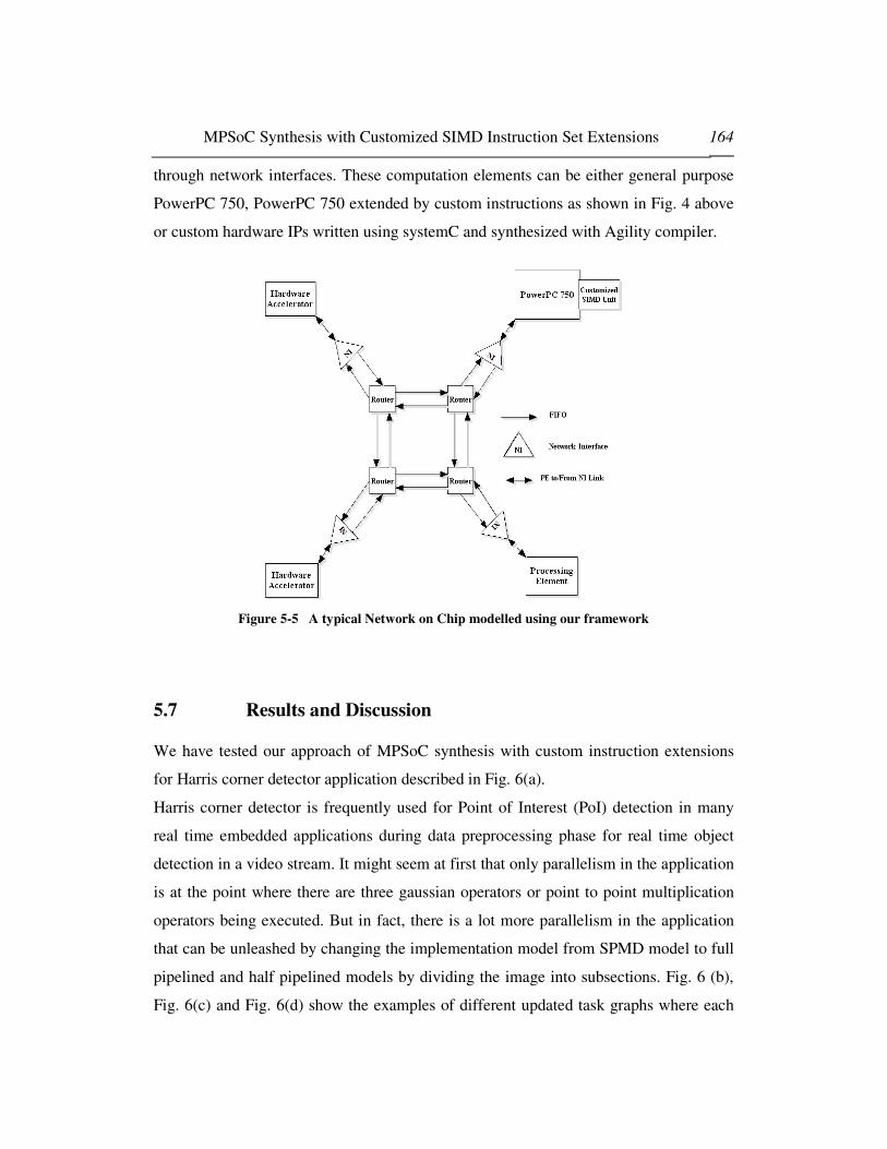
MPSoC Synthesis with Customized SIMD Instruction Set Extensions 164
through network interfaces. These computation elements can be either general purpose
PowerPC 750, PowerPC 750 extended by custom instructions as shown in Fig. 4 above
or custom hardware IPs written using systemC and synthesized with Agility compiler.
Figure 5-5 A typical Network on Chip modelled using our framework
5.7 Results and Discussion
We have tested our approach of MPSoC synthesis with custom instruction extensions
for Harris corner detector application described in Fig. 6(a).
Harris corner detector is frequently used for Point of Interest (PoI) detection in many
real time embedded applications during data preprocessing phase for real time object
detection in a video stream. It might seem at first that only parallelism in the application
is at the point where there are three gaussian operators or point to point multiplication
operators being executed. But in fact, there is a lot more parallelism in the application
that can be unleashed by changing the implementation model from SPMD model to full
pipelined and half pipelined models by dividing the image into subsections. Fig. 6 (b),
Fig. 6(c) and Fig. 6(d) show the examples of different updated task graphs where each

MPSoC Synthesis with Customized SIMD Instruction Set Extensions 165
task is divided into subtasks dealing with separate sections on an image in parallel.
Before the start of implementing our design flow on the application, we first explain the
implementation details of SIMD instruction library and HW accelerators repository to
estimate performance/ area requirements for the components.
• Custom SIMD Instruction Library:
As mentioned in previous section, we have developed a library of AltiVec
instructions in VHDL and synthesized it to get area requirements for each instruction.
Fig. 7 represents the area taken by various components of AltiVec on a Virtex-4 FPGA.
Some components like Vector Permute Units and the modules related to shift
instructions take as much as one thousand slices, which is more than 20 % of total
ML403 area, while most of the modules are less expensive in terms of area
requirements. An obvious reason for this fact is that the shift capabilities in AltiVec
instructions are more than that of a “barrel shifter” since every block of the vector can
be shifted by a different value. For standard implementation of the VPU, whole
Fig 5-6(a): Image Processing Application to be Synthesized Fig. 5.6(c): Updated Task Graph for Half Pipeline Mode
Fig. 5.6(b): Task Graph for SPMD Model Fig.5. 6(d): Task Graph for Fully Pipelined Model

MPSoC Synthesis with Customized SIMD Instruction Set Extensions 166
“crossbar” functionality has to be implemented to keep it compatible to standards
resulting in adding a lot of RTL logic. Area might have been smaller for shift
instructions if same shift value was used for every data component in the instruction.
Similarly, the instruction with saturation takes up more area because of additional logic
for implementation of saturation functionality.
Figure 5-7 Area of AltiVec Modules on Virtex-IV FPGA
• Image Processing Operators Library
We have implemented a few image processing operators in hardware as hardware
accelerators. These operators include various commonly used filters, corner detectors,
point and geometric operators. Each operator is synthesized and its area and
performance estimations are obtained. These performance vs. cost values are
benchmarked with general purpose processor and SIMD instruction extended processors
to compare various implementations of each operator. If an operator used in
application is found in the library, it is used directly from there otherwise hardware
designer has to implement the operator manually and synthesize it to get the

MPSoC Synthesis with Customized SIMD Instruction Set Extensions 167
performance and area results. For the operator found in given application, Table 2
provides a comparison of performance results for each operator in three different
implementations while Table 1 provides the area requirements of each operator when
implemented in dedicated hardware. It can be seen that computation time or hardware
accelerators is better than SIMD implementations however it should be noted that to
assure that adding a hardware accelerator results in a speedup on a system level
involving a NoC, communication time between two tasks mapped over two different
processors should also be reduced to get benefit of the dedicated hardware design effort.
On the other hand, although SIMD implementation involves programming effort in
software development (if auto-vectorization option doesn't give good results and
programmer opt or manual vectorization), there are no communication overheads
involved because extended instructions are closely coupled to the general purpose
processor where vector and scalar instructions travel simultaneously in their respective
pipelines.
Table 5-1 Synthesis Results for Harris Corner detector Chain
Area ( Computational Logic and
Memory)
Module Name
Comp. Logic
Slices
Memory
(bits)
Critical
Path
(ns)
Synth
Freq.
(MHz)
Sobel 896 131072 14.41 69.39
P2P-Mul 604 262144 11.04 90.33
Gauss 760 131072 6.32 61.1
Harris 1404 294912 19.32 51.76
Table 5-2 Performance Comparison of Operators in HW, SIMD and GPP Versions
HW
(cycles)
Cycles/Pxl SIMD
(cycles)
Cycles/Pxl GPP
( cycles)
Cycles/Pxl
Sobel 16676 4.07 24612 6.01 179670 43.86
Mul 3152 .77 5675 1.39 41990 10.25
Gauss 7966 1.94 18641 4.55 130490 31.85
Harris 13225 3.23 9522 2.32 66440 16.22

MPSoC Synthesis with Customized SIMD Instruction Set Extensions 168
For our application, performance constraint was given in terms of number of images
treated in a second. Although, we have used image blocks of 64x64 during our
simulations to keep the simulation times short, based on the cycle per pixel value
obtained with simulation results, we estimate the number of 512x512 images treated
with the same computation power in a second. Our target was to minimize the network
complexity while achieving a 60 images/second throughput for the application.
To estimate the amount of performance enhancement, we first executed our
application on a single general purpose PowerPC 750 running at 333.33 MHz. The
processor was not extended with custom instructions and no other computational
elements were used in the environment. Instruction and data cache sizes, data bus width
and related soft parameters were fixed to be kept constant or all the configurations in the
design process to make realistic comparisons. Our initial simulation results showed us
that it takes 186.4 clock cycles per pixel for performing all operation in the image
processing chain. With this performance we can only process 6.8 images in a second
that can be tremendously improved using our methodology without adding significant
area/energy costs of the hardware.
Table 5-3 Speedup of SIMD Extended Monoprocessor system vs. General Purpose Processor
Function SIMD
Version
(Cycles)
64x64 block
SIMD
Version
(Cycles/pixel)
Non-SIMD
version
(Cycles)
64x64 block
Non-SIMD
Version
(Cyc/pxl)
Area Increase for
SIMD Version
(Number of Slices)
Speedup
of Vector
over
Scalar
Version
Sobel 24612 6.01 179670 43.86 1664 7.3
Multiplication 5675 1.39 41990 10.25 271 7.4
Gauss 18641
4.55 130490 31.86 1590 7.0
Harris 9522 2.32 66440 16.22 890 6.9
Total
(Monoprocessor
System)
107082 26.14 763550 186.41 1935 7.1
MPSoC Synthesis with Customized SIMD Instruction Set Extensions 169
Another case to estimate performance improvements with SIMD extensions was
tested. In this case, we still used a mono-processor system however difference was that
the PowerPC processor was extended with custom SIMD instructions used by the
application. We observed that with slight increase in area, we could get a significant
speedup over the general purpose processor architecture. Results for each task and
overall speedup are given in table 3 below. Our results showed that SIMD extension
provided roughly seven times speedup allowing us to process 48 images/seconds. This
was a significant improvement over base processor results however performance
requirements were still not met requiring us to move to next steps in methodology
involving MPSoC with an underlying NoC.
As explained in design flow, we modelled the reference platform which was chosen
to be a multiprocessor system with an underlying NoC of 2x2 with mesh topology. This
configuration uses one general purpose processor which is not extended with any SIMD
instruction while three nodes are hardware accelerators modelled in SystemC. Our
results showed a throughput of 15 images per second which is although more than
double than the single general purpose processor results but it still needed significant
performance improvements. At this point, we can see that although coarse grained
parallelism is being exploited to a certain degree, as fine grained data parallelism is not
dealt properly, our application still far away from meeting the constraints. If our
methodology was based on traditional MPSoC synthesis techniques, we might have
needed to increase the complexity of NoC to 3x3 to have further performance
improvements. But in our case, our next exploration step involved implementing the
scalar tasks into vector versions. Bottleneck tasks are vectorized and processor is
extended according to the new instruction added in the task because of vectorization.
After simulation, we observed that vectorization of tasks had resulted in an image
throughput of 67 images per second meeting the performance constraints even with 2x2
mesh topology.
According to our methodology, once performance constraints were met, network
simplification process was started which was done by shifting some functionality as

MPSoC Synthesis with Customized SIMD Instruction Set Extensions 170
vectorized tasks instead of dedicated hardware accelerator. Bottleneck tasks are
vectorized and processor is extended according to the new instruction added in the task
because of vectorization. Tasks from hardware accelerators are shifted to extended
processor and performance results are obtained.
Table 5-4 Performance Results for Various MPSoC Configurations
Configuration Details (Task Nature) Iteration
Number Scalar Vector Hardware
Cycles
Taken
(64x64
block)
Cycles/Pixel Image
Processed per
second
1 All None None 763550 186.41 6.8
2 None All None 107082 26.14 48
3 1 gauss, 3
mul, harris
None 2 gauss,
sobel
330488 80.68 15.06
4 None 3 mul,harris 3 gauss 73413 17.92 70.95
5 None 1 gauss, 3
mul, harris
2 gauss,
sobel
77221 18.85 67.45
6 None Mul, harris,
1 gauss
1 gauss,
sobel
82837 20.22 62.88
7 None Rest of
operators
Sobel 88440 21.59 58.89
8 None Rest of
operators
2 Gauss 77586 18.94 67.13
9 None Rest of
operators
1 Gauss 83190 20.31 62.60
Last four configurations in Table 4 show the network reduction process in our
methodology. We observed that with one Gaussian operator in hardware and rest of the
operators shifted to vectorized software; our performance constraints were still met
proving strong impact of vector extended instructions on MPSoC synthesis. This
requires an MPSoC based on a customized SIMD instruction extended general purpose
processor with only one hardware accelerator. It should also be clear that with this
simple configuration, NoC might not be need and routers and network interfaces can be
simplified further to reduce the implementation complexity.

MPSoC Synthesis with Customized SIMD Instruction Set Extensions 171
5.8 Conclusions
In this chapter, we have proposed a methodology to synthesize an MPSoC with an
underlying NoC concurrently with extensible instruction set processors as individual
MPSoC nodes. Doing both synthesis in a single step exposes new relationships that
exist between mapping problem, processor architecture and network parameters. Our
experimental results prove the effectiveness of our methodology by showing that
network architecture can be significantly simplified by generating extended processors
with custom SIMD instructions on individual nodes in a NoC.
This work provides a first insight into the problem of MPSoC synthesis which allows
the designers to exploit parallelism at two different levels in a single synthesis
methodology. However further research is required on various aspects of the problem
including irregular NoC topology synthesis with custom instruction generation,
classifying applications suitable for the methodology and understanding of inter-related
parameters for MPSoC, NoC and instruction Set Extension synthesis problems.
Considering that the productivity is a major concern for industry, our methodology
already tries to address the productivity issues by simplifying the synthesis problem and
restricting the application domain to data intensive DSP applications. However, there is
still a need to automate the design flow to increase the productivity which requires
significant improvements in auto-vectorization techniques and more automation in
existing hardware and software synthesis techniques.
References
[5.1] International Technology Roadmap for Semiconductors: Design, 2005 [5.2] "New Degrees of Parallelism in Complex SOCs",MIPS Technologies, Inc. July 2002 [5.3] K. Keutzer, S. Malik, and A. R. Newton, “From ASIC to ASIP: The next design discontinuity,”
in Proc. Int. Conf. Computer Design, Freiburg, Germany, Sep. 2002, pp. 84–90. [5.4] J. Huang and A. M. Despain, “Generating instruction sets and microarchitectures from
applications,” in Proc. Int. Conf. Computer-Aided Design, San Jose, CA, Nov. 1994, pp. 391–396.

MPSoC Synthesis with Customized SIMD Instruction Set Extensions 172
[5.5] J. van Praet, G. Goossens, D. Lanneer, and H. De Man, “Instruction set definition and instruction set selection for ASIPs,” in Proc. Int. Symp. High-Level Synthesis, Niagara, ON, Canada, May 1994, pp. 11–16.
[5.6] R. Leupers and P. Marwedel, “Instruction set extraction from programmable structures,” in Proc.
Eur. Design Automation Conf., Paris, France, Sep. 1994, pp. 156–160. [5.7] C. Liem, T.May, and P. Paulin, “Instruction-set matching and selection for DSP and ASIP code
generation,” in Proc. Eur. Design Automation Conf., Paris, France, Mar. 1994, pp. 31–37. [5.8] W. E. Dougherty, D. J. Pursley, and D. E. Thomas, “Subsetting behavioral Intellectual property
for low power ASIP design,” J. VLSI Signal Process., vol. 21, no. 3, pp. 209–218, Jul. 1999. [5.9] K. Kucukcakar, “An ASIP design methodology for embedded systems,” in Proc. Int. Symp.
HW/SW Codesign, Rome, Italy, May 1999, pp. 17–21. [5.10] H. Choi, J.-S. Kim, C.-W. Yoon, I.-C. Park, S. H. Hwang, and C.-M. Kyung, “Synthesis of
application specific instructions for embedded DSP software,” IEEE Trans. Comput., vol. 48, no. 6, pp. 603–614, Jun. 1999.
[5.11] J. E. Lee, K. Choi, and N. Dutt, “Efficient instruction encoding for automatic instruction set design of configurable ASIPs,” in Proc. Int. Conf. Computer-Aided Design, San Jose, CA, Nov. 2002, pp. 649–654.
[5.12] F. Sun, S. Ravi, A. Raghunathan, and N. K. Jha, “Synthesis of custom processors based on extensible platforms,” in Proc. Int. Conf. Computer-Aided Design, San Jose, CA, Nov. 2002, pp. 641–648.
[5.13] Fei Sun, Srivaths Ravi, Anand Raghunathan, Niraj K. Jha, “A scalable application-specific processor synthesis methodology”, in Proc. Int. Conf. Computer-Aided Design, San Jose, CA, Nov. 2003, pp. 283–290.
[5.14] N. Cheung, S. Parameswaran, and J. Henkel, “INSIDE: Instruction selection/identification and design exploration for extensible processors,” in Proc. Int. Conf. Computer-Aided Design, San Jose, CA, Nov. 2003, pp. 291–297.
[5.15] N. Cheung, S. Parameswaran, J. Henkel, and J. Chan, “MINCE: Matching instructions using combinational equivalence for extensible processors,” in Proc. Design Automation Test Europe
Conf., Paris, France, Feb. 2004, pp. 1020–1027. [5.16] K. Atasu, L. Pozzi, and P. Ienne, “Automatic application-specific instruction-set extensions
under microarchitectural constraints,” in Proc. Design Automation Conf., Anaheim, CA, Jun. 2003, pp. 256–261.
[5.17] N. Clark, H. Zhong, W. Tang, and S. Mahlke, “Processor acceleration through automated instruction set customization,” in Proc. Int. Symp. Microarchitecture, San Diego, CA, Dec. 2003, pp. 40–47.
[5.18] A. Peymandoust, L. Pozzi, P. Ienne, and G. De Micheli, “Automatic instruction-set extension and utilization for embedded processors,” in Proc. Int. Symp. Application-Specific Systems,
Architectures, and Processors, Hague, The Netherlands, Jun. 2003, pp. 108–118. [5.19] P. Biswas and N. Dutt, “Greedy and heuristic-based algorithm for synthesis of complex
instructions in heterogeneous-connectivity-based DSPs,” School Inf. Comput. Sci., Univ. California, Irvine, Tech. Rep. 03-16, May 2003.
[5.20] P. Biswas, K. Atasu, V. Choudhary, L. Pozzi, N. Dutt, and P. Ienne, “Introduction of local memory elements in instruction set extensions,” in Proc. Design Automation Conf., San Diego, CA, Jun. 2004, pp. 729–734.
[5.21] D. Goodwin and D. Petkov, “Automatic generation of application specific processors,” in Proc.
Int. Conf. Compilers, Architecture, and Synthesis Embedded Systems, San Jose, CA, Oct. 2003, pp. 137–147.
[5.22] M. O. Cheema, O. Hammami, "Application-specific SIMD synthesis for reconfigurable architectures", Special Issue on FPGAs of Microprocessor and Microsystems, Volume 30, Issue 6, Pages 398-412, September 2006
[5.23] K. K. Ryu, V. J. Mooney III, “Automated Bus Generation for Multiprocessor SoC Design”, DATE 2003
[5.24] S. Murali, G. De Micheli, “An Application-Specific Design Methodology for STbus Crossbar Generation”, DATE 2005

MPSoC Synthesis with Customized SIMD Instruction Set Extensions 173
[5.25] "Constraint Driven Bus Matrix Synthesis for MPSoC", Processdings of ASP-DAC 2006, Page 30-35
[5.26] L. Benini and G. De Micheli, “Networks on chips: a new SoC paradigm,” IEEE Comput., vol. 35, no. 1, pp. 70–78, Jan. 2002.
[5.27] W. Dally and B. Towles, “Route packets, not wires: On-chip interconnection networks,” in Proc.
DAC, 2001, pp. 684–689. [5.28] A. Hemani et al., “Network on a chip: An architecture for billion transistor era,” in Proc. IEEE
NorChip Conf., 2000, pp. 166–173. [5.29] A. Jantsch and H. Tenhunen, Eds., Networks-on-Chip. Norwell, MA: Kluwer, 2003. [5.30] T. Bjerregaard and S. Mahadevan,"A Survey of Research and Practices of Network-on-Chip",
ACM Computing Surveys, Vol. 38, March 2006, Article 1. [5.31] Umit Y. Ogras, Jingcao Hu, Radu Marculescu, " Key Research Problems in NoC Design: A
Holistic Perspective", Proceedings of the 3rd IEEE/ACM/IFIP international conference on Hardware/software codesign and system synthesis, Jersey City, NJ, USA Pages: 69 - 74 , 2005
[5.32] S. Kumar et al., “A Network on Chip Architecture and Design Methodology,” Proc. Int’l Symp. VLSI 2002, pp. 105-112, Apr. 2002.
[5.33] E.B. Van der Tol and E.G.T. Jaspers, “Mapping of MPEG-4 Decoding on a Flexible Architecture Platform,” Proc. SPIE 2002, pp. 1-13, Jan. 2002.
[5.34] A. Pinto et al., “Efficient Synthesis of Networks on Chip,” Proc. Int’l Conf. Computer Design 2003, pp. 146-150, Oct. 2003.
[5.35] J. Hu and R. Marculescu, “Energy-Aware Mapping for Tile-Based NOC Architectures under Performance Constraints,” Proc. Asia and South Pacific Design Automation Conf. 2003, pp. 233-239, Jan. 2003.
[5.36] D. Bertozzi, A. Jalabert, S. Murali, R. Tamhankar, S. Stergiou, L. Benini, Giovanni De Micheli, " NoC Synthesis Flow for Customized Domain Specific Multiprocessor Systems-on-Chip", IEEE Transactions on Parallel and Distributed Systems, Vol16,No; 2, Feb 2005
[5.37] Kees Goossens, John Dielissen, Om Prakash Gangwal, Santiago Gonz´alez Pestana, Andrei R˘adulescu, and Edwin Rijpkema, "A Design Flow for Application-Specific Networks on Chip with Guaranteed Performance to Accelerate SOC Design and Verification", Proceedings of the Design, Automation and Test in Europe Conference and Exhibition (DATE’05)
[5.38] A.Pinto et al., “Efficient Synthesis of Networks on Chip”, ICCD 2003, pp. 146- 150, Oct 2003. [5.39] W.H.Ho, T.M.Pinkston, “A Methodology for Designing Efficient On-Chip Interconnects on
Well-Behaved Communication Patterns”, HPCA 2003, pp. 377- 388, Feb 2003. [5.40] T. Ahonen et al. ”Topology Optimization for Application Specific Networks on Chip”, Proc.
SLIP 04. [5.41] K. Srinivasan et al., “An automated technique for topology and route generation of application
specific on-chip interconnection networks", Proceedings of ICCAD 2005, 6-10 Nov. 2005 Page(s): 231 – 237
[5.42] David Sheldon, Rakesh Kumar, Frank Vahid, Roman Lysecky, and Dean Tullsen. "Application-Specific Customization of Parameterized FPGA Soft-Core Processors". International Conference on Computer-Aided Design, ICCAD, San Jose, November 2006
[5.43] Rakesh Kumar, Dean Tullsen, and Norman Jouppi. " Core Architecture Optimization for Heterogeneous Chip Multiprocessors". International Conference on Parallel Architectures and Compilation Techniques, PACT, Seattle, April 2006
[5.44] Automatic Application-Specific Microarchitecture Reconfiguration; by Shobana Padmanabhan, Ron K. Cytron, Roger D. Chamberlain and John W. Lockwood; 13th Reconfigurable Architectures Workshop (RAW), Apr 25-26, 2006
[5.45] R. Kumar, K. I. Farkas, N. P. Jouppi, P. Ranganathan, and D. M. Tullsen. Single-ISA Heterogeneous Multi-core Architectures: The Potential for Processor Power Reduction. In International Symposium on Microarchitecture, Dec. 2003.
[5.46] Fei Sun, Srivaths Ravi, Anand Raghunathan, Niraj K. Jha "Application-Specific Heterogeneous Multiprocessor Synthesis Using Extensible Processors", IEEE Transactions on Computer Aided Design of Integrated circuits and systems, Vol 25, No.9, Sep 2006

MPSoC Synthesis with Customized SIMD Instruction Set Extensions 174
[5.47] PowerPC Processor reference Guide-Embedded Development Kit EDK 7.1i-UG 018(v 3.0) August 20, 2004
[5.48] M. Phillip et al,”AltiVec Technology: Accelerating Media Processing Across the Spectrum”, In HOTCHIPS10, Aug 1998.
[5.49] Velocity Engine: http://developer.apple.com/hardware/ve/index.html [5.50] Platform Specification Format Reference Manual- Embedded Development Kit EDK 7.1i-UG
131 (v3.0) Aug 20, 2004 [5.51] CoreConnect™ bus architecture, IBM Microelectronics Whitepaper, 1999 [5.52] ML 40x Evaluation Platform User Guide, UG080 (v2.0) P/N 0402337 February 28, 2005, 2004-
2005 Xilinx, Inc. [5.53] Xilinx ISE 7.1 Synthesis and Verification User Guide 7.1i-UG 131 (v3.0) Aug 20, 2004 [5.54] PowerPC Simulator: http://microlib.org/projects/ppc750sim/ [5.55] Coppola, M.Curaba, S.Grammatikakis, M.D.Maruccia, G.Papariello, F. "OCCN: a network-on-
chip modeling and simulation framework", Proceedings of DATE 2004, Vol.3, Page 174-179 [5.56] Agility : http://www.celoxica.com/products/agility/default.asp [5.57] Dorit Nicholas, “Autovectorization in GCC”, GCC Developers’ Summit, pp 105-117, 2004 [5.58] VAST Code Optimizer, Available: http://www.crescentbaysoftware.com/vast_altivec.html

MPSoC Synthesis with Customized SIMD Instruction Set Extensions 175
6. Conclusions and Perspective
This chapter concludes the thesis by giving a summary of the previous chapters, where
the key ideas and design flows are discussed. Based on the present state of our proposed
design flow for combined SIMD customized instruction set generation as well as
MPSoC synthesis, this chapter gives an overview about future directions for research
with the objective to extend the methodology for more general types of NoC and
MPSoC architectures.
6.1 Summary of the Thesis
In this thesis we have proposed a design methodology for MPSoC design with
custom SIMD extended processor synthesis. The salient features of the methodology
include:
� Custom processor extension synthesis for data intensive applications.

MPSoC Synthesis with Customized SIMD Instruction Set Extensions 176
� MPSoC and NoC Synthesis at high abstraction layers
� Studying the effect of Processor customization on NoC architectures and vice
versa
Our SIMD customization design flow, unlike existing ASIP synthesis techniques,
targets specifically data intensive multimedia applications. As a result, our instruction
superset (set of candidate instructions) consists for well established industry standards
simplifying the tasks of instruction set selection and instruction matching resulting in
better design productivity as compared to existing methodologies targeting fine grained
parallelism.
We recommend the use of behavioural synthesis, platform based design and TLM
based modelling to achieve higher productivity without compromising the performance
of synthesized systems. In our flow of MPSoC design, area and energy consumption
issues are tackled at TLM level resulting in early bottleneck detection and hence shocks
in late stages of the projects.
Lastly, our design flow for integrated custom processor extensions along with
MPSoC and NoC synthesis is one of the very first attempts to combine two inter-related
sets of design methodologies which are often considered as two different problems.
ASIP design and MPSoC design problems if combined together reveal a strong
relationship between mapping problem and processor customization. To the best of our
knowledge, it is the first work in this regard. As a first case of combined ASIP and
MPSoC synthesis, we have shown that NoC architecture can be significantly simplified
with the help of efficient processor customization resulting in lesser area and energy
consumption.
6.2 Future Research Directions
Our work can be extended in several different research directions. Here are the few
interesting directions requiring further inspection and research work.

MPSoC Synthesis with Customized SIMD Instruction Set Extensions 177
1. Results of customized SIMD (vector) instruction synthesis are strongly dependent
on compiler performance. Evolution in compiler techniques especially in
vectorization will directly affect the improved design flows for ASIP design with
much more automation possible in the whole design process.
2. Customized SIMD synthesis is a subset of generalized ASIP synthesis problem. As
productivity remains a major issue, we are of the opinion that more domain specific
ASIP design methodologies will appear in near future separately focusing on data
level SIMD/vector type of parallelism and instruction level VLIW type of
parallelism.
3. Trend on number of cores on a single chip will keep on increasing in foreseeable
future. Heterogeneous MPSoC with irregular NoC topologies will evolve to meet
application specific system on chip solutions. As shown in chapter 5, number of
cores can be significantly reduced by introducing ASIP synthesis design process in
MPSoC design flows which will allow more useful utilization of resources without
unnecessarily complicating the NoC structure. However our applications were not as
large as usual application used in industry. More work needs to be done to apply our
methodology using larger industry scale applications which might results in many
undiscovered aspects of inter-related system design parameters.
The main contribution of the thesis is to show how ASIP design methodologies i.e.
customized SIMD extensions can be introduced in MPSoC design process at higher
level of abstraction. Although we have not used larger examples, the thesis should
indicate the importance of our methodology that emphasized on processor
customization concurrently with MPSoC and NoC synthesis.

Abstract:
An efficient system level design methodology for MPSoC synthesis should be able to exploit both coarse grained and fine grained parallelism inherent in the target application. Traditional MPSoC synthesis methodologies proposed so far emphasize on coarse grained (task level) parallelism exploitation where processor cores architecture is fixed before the start of multiprocessor design. On the other hand, extensible processor synthesis methodologies emphasize on fine grained (instruction level) parallelism ignoring the task level parallelism exploitation through multiprocessor design. We have observed that the problems of processor extension synthesis and general MPSoC synthesis are closely related and it is important to integrate both problems together to get optimal result. However, combining both problems complicates the synthesis even more because of large design spaces associated with these problems. In this thesis, we have proposed an MPSoC design methodology that combines the problem of traditional MPSoC synthesis with extensible processor synthesis to take benefit of both levels of parallelism.
Résumé:
Une méthode de conception de niveau de système efficace de synthèse MPSOC devrait être capable d'exploiter à la fois les parallélismes à gros grains et à grains fins inhérents à l'application cible. Les méthodes de synthèse traditionnelles ont jusqu’à lors proposé de mettre l’accent sur l’exploitation de parallélismes à gros grains (niveau des tâche) dans lesquelles l’architecture des coeurs de processeurs est définie avant le début de la conception des multiprocesseurs. D’un autre côté, des méthodologies de synthèse de processeur étendu portent leur attention sur les parallélismes à grains fins (niveau d’instruction) en ignorant l'exploitation des parallélismes de niveau des tâches par la conception de multiprocesseurs. Nous avons observé que les problèmes de synthèse d’extension de processeur et la synthèse général MPSoC sont étroitement reliés et il est important d’intégrer les deux problèmes ensemble pour obtenir un résultat optimal. Cependant, la combinaison des deux problèmes complique beaucoup plus la synthèse à cause des grands espaces de conception associés avec ces problèmes. Dans cette thèse, nous avons proposé une méthodologie de conception MPSoC qui combine le problème de synthèse MPSoC traditionnelle avec la synthèse de processeur étendu pour bénéficier des deux niveaux de parallélisme. This thesis has been printed in the Ecole Nationale Superieure de Techniques Avancées. Cette these a été imprimé à l’ecole Nationale Superieure de Techniques Avancées


