Embed Size (px)
Citation preview

ACCESSORIES
TABLE OF CONTENTS
ITEM PAGE
ANCHOR BOLTS ..........................................................................................A003
MERCURY LEVEL TILT SWITCH .................................................................A005
4" "F" CONVERSION KIT .....................................................................…...A007
6" "F" CONVERSION KIT ............................................................................A009
CHAIN GRABBER LIFTING SYSTEM .......................................…...............A011
ALUMINUM ACCESS DOORS ..................................................…................A013
MOISTURE DETECTION RELAYS
DUAL-CHANNEL - ADJUSTABLE TYPEWITH INDICATING LIGHT…………………………………………....................A017
COMBINATION SEAL FAILURE / OVERTEMP. - SIMPLEXADJUSTABLE TYPE WITH INDICATING LIGHT………………....................A019
SERIES 16 - NO ENCLOSURE ..............................................…...................A021
SERIES 2800A - ENCLOSED - NO INDICATING LIGHT..............................A023
SERIES 2810A - ENCLOSED - WITH INDICATING LIGHT..........................A025
CONTROL PANELS ......................................................................................A027
SUBMERSIBLE SOLIDS-HANDLING WASTEWATER PUMPS
SECTION 2152 & 2235
ACCESSORIES
Date 4/18/11 PAGE A001
R

2 1/4
3/4
3/4
410 10
722
722
722
8
8
8
1
5/8
ITEM
Submersible BaseElbow for:
SR
EL
Dry Pit Submersibles With Support Elbow
All Others
A B C D E
B
CDA
B
E
C
D
ACarbon Steel
AISI 304 S.S.
Heavy Flat Washer
Heavy Hex Nut UNC2 Th'd
Heavy Flat Washer
Heavy Hex Nut UNC2 Th'd
Anchor Bolt Sleeve
Heavy Flat Washer
Heavy Hex Nut UNC2 Th'd
Mounting FlangeOf EquipmentTo Be Mounted
Non-Shrink Grout.Poured In Place,After EquipmentSetting.
"L" Type Anchor Bolt
Anchor Bolt Sleeve,As An In-PlaceForm To Provide AGrout Pocket AroundThe Anchor Bolt.
ANCHOR BOLT DETAIL
SUBMERSIBLE SOLIDS-HANDLING WASTEWATER PUMPS
SECTION 2152 & 2235
ACCESSORIES
Date 9/1/07 PAGE A003
R

The float is a direct acting float switch. Each float contains asingle-pole snap-action switch which actuates when the longitudinalaxis of the float is horizontal and deactuates when the liquidlevel falls 3-1/2" below the activation level.
The float is a chemical resistant polypropylene casing with a firmly bonded electrical cable protruding. One end of the cableis permanently connected to the enclosed snap-action switch andthe entire assembly is encapsulated to form a completelywatertight and impact resistant unit.
Mercury-Free Level Tilt SwitchesPilot Duty Industrial Control Equipment
NOTE: Actual shape of float may vary slightly from these illustrations.
SwitchArrangement
CableLength
(ft.)
Suspended Types
Model No. Ship Wt. (lb.)
Normally Open
' '
' '
' '
30
40
50
60
GSI30NO
GSI40NO
GSI50NO
GSI60NO
5
6
7
8
YeomansChicagoCorporation
YeomansChicagoCorporation
Type "GSI" with Stabilizing Weight
PVC Type SJO - 2 cond. # 18 AWG 41 Strand300 volt electrical cord
Polypropylene Casingcontains hermetically sealedsnap-action switchN.O. - Black
Pilot Duty7 AMPS 120 VAC3.5 AMPS 240 VAC
P/N C9-4-37Stainless Steel Wall Mounting Bracketw/ four (4) adjustable cord grips forType "GSI" Floats
Junction Box (if required)To power and motor starters
High Water Alarm (Optional)
Start Lag / Stand-by Pump
Start Lead / Duty Pump
Common All Pumps Stop
Typcal "Duplex" Control Arrangement
Typical U.L. Pump Control Curcuit
NOStartLag
NOStartLead
NOCommon
Stop
Pump Down
Line Voltage
R1
R1
R1R2
R2
R2
Pilot ContactLead PumpMotor Starter
Pilot ContactLag / Stand-by PumpMotor Starter
4.25"
3"
SUBMERSIBLE SOLIDS-HANDLING WASTEWATER PUMPS
SECTION 2152 & 2235
ACCESSORIES
Date 12/12/07 PAGE A005
R
Cast Iron
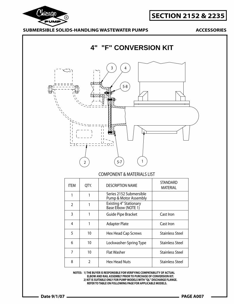
COMPONENT & MATERIALS LIST
ITEM QTY. DESCRIPTION NAMESTANDARDMATERIAL
1
2
3
4
5
6
1
1
1
1
10
10
Series 2152 Submersible Pump & Motor AssemblyExisting 4" Stationary Base Elbow (NOTE 1)
Guide Pipe Bracket
Adapter Plate
Hex Head Cap Screws
Lockwasher-Spring Type
Cast Iron
Stainless Steel
Stainless Steel
7 10 Flat Washer Stainless Steel
8 Hex Head Nuts Stainless Steel2
3 4
5-8
12 5-7
4" "F" CONVERSION KIT
NOTES: 1) THE BUYER IS RESPONSIBLE FOR VERIFYING COMPATABILITY OF ACTUAL ELBOW AND RAIL ASSEMBLY PRIOR TO PURCHASE OF CONVERSION KIT. 2) KIT IS SUITABLE ONLY FOR PUMP MODELS WITH "QL" DISCHARGE FLANGE. REFER TO TABLE ON FOLLOWING PAGE FOR APPLICABLE MODELS.
SUBMERSIBLE SOLIDS-HANDLING WASTEWATER PUMPS
SECTION 2152 & 2235
ACCESSORIES
Date 9/1/07 PAGE A007
R

CABLE HANGERS, IF REQUIRED (BY OTHERS)
10 1/4E
F
G
RECOMMENDED SUBMERGED DEPTH
LIFTING BAILMOTOR POWER & CONTROL CABLES
2 TYP
C
A
B
D
2 TYP.
NOTE: ALL DIMENSIONS ARE IN INCHES.
CLEAR OPENING
NOT CERTIFIED FOR CONSTRUCTION PURPOSES. REFER TO FACTORY FOR CERTIFIED INSTALLATION DRAWINGS
NOTE 1: THE BUYER IS RESPONSIBLE FOR VERIFYING COMPATABILITY OF ACTUAL ELBOW AND RAIL ASSEMBLY PRIOR TO PURCHASE OF CONVERSION KIT.
MOTOR
HP
1
1 1/2
2
3
5
7 1/2
10
15
20
25
30
40
MOTOR FRAME CHART
THREE PHASE - 60 HERTZ
1750 1160 875
140140
180
180
140
210
210
210
250
250250
DIMENSION CHART
4073
19 1/2
8 3/4
6 1/4
7 1/4 6 1/4
6
22 3/410356542250
5 1/211 3/430 18 5/8
18 1/8 13 1/2 11 3/8
4103L
40x28
28x19
26x17
34x25
32x22
6006038
9356440
5005736
3854731
4805736
3654832
3254631
4355736
3204731
2804429
2904731
210
29
210
250
10 1/223 7/8 14 3/8
621 7/8 16 1/4 13 7/8
4153
4123
4103S
4092.5
G
4072.5
EDCB
250140
180
140
180
140
180
210
180
44
210
A MOTORFRAME
APPROX.WT. #
FPUMPMODEL
CLEAROPENING
(MIN.)
10 3/811 3/416 3/8 7
Hz Motor Frame
Model
Totally Enclosed Non-Ventilated w/Thermal Protection & Moisture Detection
RPM,HP,
Rated for GPM at
PhaseVolts
Ft.TDH.
Pump
LIST OF EQUIPMENT FURNISHED:
SUBMERSIBLE SOLIDS-HANDLING WASTEWATER PUMPS
SECTION 2152 & 2235
ACCESSORIES
R
PAGE A008 Date 9/1/07
REVISION DATEISSUE
JOB:
S.O.
5006100OUTLINE DWG #

NOTES: 1) THE BUYER IS RESPONSIBLE FOR VERIFYING COMPATABILITY OF ACTUAL ELBOW AND RAIL ASSEMBLY PRIOR TO PURCHASE OF CONVERSION KIT. 2) KIT IS SUITABLE ONLY FOR PUMP MODELS WITH "QL" DISCHARGE FLANGE. REFER TO TABLE ON FOLLOWING PAGE FOR APPLICABLE MODELS.
Stainless Steel
Stainless Steel
Cast Iron
Neoprene
Lockwasher-Spring Type
Hex Head Cap Screws
Gasket
Guide Pipe Bracket
Existing 6" Stationary Base Elbow (NOTE 1)
Series 2152 Submersible Pump & Motor Assembly
8
8
1
1
1
1
6
5
4
3
2
1
STANDARDMATERIAL
DESCRIPTION NAMEQTY.ITEM
COMPONENT & MATERIALS LIST
2
3
14 65
6" "F" CONVERSION KIT
SUBMERSIBLE SOLIDS-HANDLING WASTEWATER PUMPS
SECTION 2152 & 2235
ACCESSORIES
Date 9/1/07 PAGE A009
R

NOTE: ALL DIMENSIONS ARE IN INCHES.
2 TYP.
2 TYP.
D
B
A
C
CLEAR OPENING
E10 7/8
RECOMMENDED SUBMERGED DEPTH
CABLE HANGERS, IF REQUIRED (BY OTHERS)
F
G
LIFTING BAILMOTOR POWER &CONTROL CABLES
NOT CERTIFIED FOR CONSTRUCTION PURPOSES. REFER TO FACTORY FOR CERTIFIED INSTALLATION DRAWINGS
NOTE 1: THE BUYER IS RESPONSIBLE FOR VERIFYING COMPATABILITY OF ACTUAL ELBOW AND RAIL ASSEMBLY PRIOR TO PURCHASE OF CONVERSION KIT.
250250
250
210
210
210
140
180
180
140140
87511601750
THREE PHASE - 60 HERTZ
MOTOR FRAME CHART
1
1 1/2
2
3
5
7 1/2
10
15
20
25
30
40
50
60
75
100
125
150
200
MOTOR
HP
320
360
320
360
320
360
12 629 3/4 213/4 18 7/8
CLEAROPENING
(MIN.)PUMP
MODELF APPROX.
WT. #MOTORFRAME
A
46
360
320
250
210
320
250
210
180 465
B C D E
DIMENSION CHART
6123
G
6153 22 1/824 3/434 1/2 613 3/8
36
360
41 51 580
43 55 1000
46 57 1415
50 60 2000
42 52 750
44 56 1075
47 58 1525
51 61 1950
40X28
45X31
Model
Totally Enclosed Non-Ventilated w/Thermal Protection & Moisture Detection
RPM,HP,
Rated for GPM at
Phase
Volts
Ft.TDH.
Pump
LIST OF EQUIPMENT FURNISHED:
Hz Motor Frame
SUBMERSIBLE SOLIDS-HANDLING WASTEWATER PUMPS
SECTION 2152 & 2235
ACCESSORIES
R
PAGE A010 Date 9/1/07
REVISION DATEISSUE
JOB:
S.O.
5006101OUTLINE DWG #

CHAIN GRABBER LIFTING SYSTEM
1/2 7/8 3/4
9/1621/323/8
7/169/32 17/32B
A
Dimensions are approximate.
ChainSize
Inches
Dimensions(inches)
A B
Cam-Alloy Grab Links
Hoist
ChainGrabLink
NylonCord*
LiftingChain
1. Connect grab link to hoist and slip nylon cord* thru link.
* Optional stainless steel cable is available in lieu of nylon cord.
2. Lower the grab link until it engages the lifting chain.
3. Release tension on lifting chain so that it engages the grab link and gradually hoists pump.
4. On returning pump to discharge elbow lower hoist cable until it is slack. By eliminating slack in nylon cord* grab link will disengage from lifting chain.
SUBMERSIBLE SOLIDS-HANDLING WASTEWATER PUMPS
SECTION 2152 & 2235
ACCESSORIES
Date 9/1/07 PAGE A011
R

ALUMINUM ACCESS DOORS Single LeafDrwg. No. 107772
E
A
3
BFD
C
AUTOMATIC HOLD OPENARM WITH RED VINYL GRIP
NOTE:
-MATERIAL: ALUMINUM WITH STAINLESS STEEL BOLTS, NUTS, AND HINGES
-LOADING: 150 OR 300 LBS. PER SQ. FOOT
CLEAR OPENING
(LOADING)XX
1
(B)(A)
S.S. HINGESWITH TAMPER PROOF BOLTS
FLUSH DROPHANDLE
FLOOR PLATE3/16" FOR 150 P.S.F.1/4" FOR 300 P.S.F.
STAPLE
SUBMERSIBLE SOLIDS-HANDLING WASTEWATER PUMPS
SECTION 2152 & 2235
ACCESSORIES
Date 9/1/07 PAGE A013
R

ALUMINUM ACCESS DOORSThe frame shall be extruded aluminum with an integral anchor flange and seat. The access door shall be equipped with a flush aluminum drop handle, which shall not protrude above the cover and an automatic hold-open arm with red vinyl grip on a release handle. Hinges shall be stainless steel with tamper proof stainless steel bolts and nuts, and shall be removable for maintenance after the access door is cast in place. The access door shall be furnished with mill finish.
Optional Features:Slamlock
Compression springs
Safety Chain Cable Holder Holes for cable holder and guide bracket
Single Leaf 150 P.S.F. Loading 300 P.S.F. Loading
Size Overall Size Clear
Opening Clear Opening
A B C D Mat'l Thk E F
Wt. (lbs.)
Mat'l Thk E F
Wt. (lbs.)
24 24 30 30 3/16 21 23 30 1/4 21 23 40 24 30 30 36 3/16 21 29 40 1/4 21 29 50 24 36 30 42 3/16 21 35 45 1/4 21 35 55 30 30 36 36 3/16 27 29 45 1/4 27 29 55 30 36 36 42 3/16 27 35 50 1/4 26 35 65 30 48 36 54 3/16 27 47 65 1/4 26 47 80 36 36 42 42 3/16 33 35 60 1/4 32 35 75 36 48 42 54 3/16 33 47 70 1/4 32 47 90 42 42 48 48 3/16 38 41 75 1/4 38 41 95
Double Leaf 150 P.S.F. Loading 300 P.S.F. Loading
Size Overall Size Clear Opening Clear
Opening A B C D
Mat'l Thk E F
Wt. (lbs.)
Mat'l Thk E F
Wt. (lbs.)
30 48 36 54 3/16 29 44 65 1/4 29 43 85 30 54 36 60 3/16 29 50 70 1/4 29 49 90 36 48 42 54 3/16 35 44 75 1/4 35 42 95 36 60 42 66 3/16 35 56 90 1/4 35 53 115 42 48 48 54 3/16 41 43 85 1/4 41 42 105 48 48 54 54 3/16 47 43 95 1/4 47 41 120 48 54 54 60 3/16 47 49 105 1/4 47 47 130 48 72 54 78 3/16 47 66 130 1/4 47 63 165 60 60 66 66 3/16 59 53 140 1/4 59 54 170
NOTE: All dimensions are in inches.
SUBMERSIBLE SOLIDS-HANDLING WASTEWATER PUMPS
SECTION 2152 & 2235
ACCESSORIES
R
PAGE A014 Date 9/1/07

E
A
3
BFD
C
AUTOMATIC HOLD OPENARM WITH RED VINYL GRIP
NOTE:
-MATERIAL: ALUMINUM WITH STAINLESS STEEL BOLTS, NUTS, AND HINGES
-LOADING: 150 OR 300 LBS. PER SQ. FOOT
CLEAR OPENING
(LOADING)XX
1
(B)(A)
S.S. HINGESWITH TAMPER PROOF BOLTS
FLUSH DROPHANDLE
FLOOR PLATE3/16" FOR 150 P.S.F.1/4" FOR 300 P.S.F.
STAPLE
ALUMINUM ACCESS DOORS Double LeafDrwg. No. 107773
SUBMERSIBLE SOLIDS-HANDLING WASTEWATER PUMPS
SECTION 2152 & 2235
ACCESSORIES
Date 9/1/07 PAGE A015
R

DUAL-CHANNEL SEAL FAILURE ALARM RELAYP/N C9-7-79
The dual seal failure module is a specialized control for monitoring seal failure. Each relay provides monitoring of two (2) submersible pump motors. Leaks are detected by sensing the conductivity of the contaminated fluid through the moisture detection probes located in the motor seal chamber and stator housing. In the event of a seal leak, the module energizes one of its SPST output relays indicating that seal maintenance or replacement is required before the motor is damaged. The sensitivity of the probe inputs is field adjustable. When the resistance between one of the probe inputs and the common connection drops below the sensitivity setting, the corresponding output relay and LED are activated.
SUBMERSIBLE SOLIDS-HANDLING WASTEWATER PUMPS
SECTION 2152 & 2235
ACCESSORIES
Date 9/1/07 PAGE A017
R

COMBINATION SEAL FAILURE / OVERTEMPSIMPLEX ALARM RELAY
P/N C9-7-80
SUBMERSIBLE SOLIDS-HANDLING WASTEWATER PUMPS
SECTION 2152 & 2235
ACCESSORIES
Date 9/1/07 PAGE A019
R
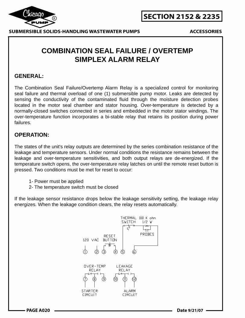
COMBINATION SEAL FAILURE / OVERTEMPSIMPLEX ALARM RELAY
GENERAL:
The Combination Seal Failure/Overtemp Alarm Relay is a specialized control for monitoring seal failure and thermal overload of one (1) submersible pump motor. Leaks are detected by sensing the conductivity of the contaminated fluid through the moisture detection probes located in the motor seal chamber and stator housing. Over-temperature is detected by a normally-closed switches connected in series and embedded in the motor stator windings. The over-temperature function incorporates a bi-stable relay that retains its position during power failures.
OPERATION:
The states of the unit's relay outputs are determined by the series combination resistance of the leakage and temperature sensors. Under normal conditions the resistance remains between the leakage and over-temperature sensitivities, and both output relays are de-energized. If the temperature switch opens, the over-temperature relay latches on until the remote reset button is pressed. Two conditions must be met for reset to occur: 1- Power must be applied 2- The temperature switch must be closed
If the leakage sensor resistance drops below the leakage sensitivity setting, the leakage relay energizes. When the leakage condition clears, the relay resets automatically.
SUBMERSIBLE SOLIDS-HANDLING WASTEWATER PUMPS
SECTION 2152 & 2235
ACCESSORIES
R
PAGE A020 Date 9/21/07
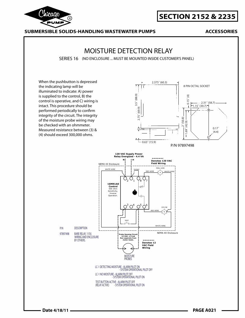
When the pushbutton is depressedthe indicating lamp will beilluminated to indicate: A) poweris supplied to the control, B) thecontrol is operative, and C) wiring is intact. This procedure should be performed periodically to con�rm integrity of the circuit. The integrity of the moisture probe wiring may be checked with an ohmmeter. Measured resistance between (3) & (4) should exceed 300,000 ohms.
P/N 97897498
2.375˝ (60.3)8 PIN OCTAL SOCKET
2.31˝ (58.7)
0.17˝(4.4)
1.15˝ (39.7)3.5˝
(88.
9)
2˝ (5
0.8)
1.69
˝ (42
.9)
0.15
˝ (4)
2.75
˝ (69
.9)
0.63˝ (15.9)
LC-1 DETECTING MOISTURE - ALARM PILOT ON - SYSTEM OPERATIONAL PILOT OFFLC-1 NO MOISTURE - ALARM PILOT OFF - SYSTEM OPERATIONAL PILOT ONTEST BUTTON ACTIVE - ALARM PILOT OFF(RELAY ACTIVE) - SYSTEM OPERATIONAL PILOT ON
MOISTUREPROBES
P/N DESCRIPTION
97897498 BARE RELAY, 115V,WIRING AND ENCLOSURE BY OTHERS.
Probe Sensing Circuit12 VAC, 1.5 mA
Run separate frommotor leads.
16MN1A0Control50K Ohm
Sensitivity,Inverse
Operation.
SYS OK
G
120 VAC Supply PowerRelay Energized - 4.4 VA
HN
WHITE WIRE
RED WIRE
Denotes 12VAC FieldWiring
NEMA 4X Enclosure
NEMA 4X Enclosure
12 8 7
3 4 5 6
SEAL LEAK
ARED WIRE
repmuJERIW ETIHW
Denotes 120 VACField Wiring
WHITE WIRE
TEST
MOISTURE DETECTION RELAYSERIES 16 (NO ENCLOSURE ... MUST BE MOUNTED INSIDE CUSTOMER'S PANEL)
SUBMERSIBLE SOLIDS-HANDLING WASTEWATER PUMPS
SECTION 2152 & 2235
ACCESSORIES
R
PAGE A021Date 4/18/11

LC-1 DETECTING MOISTURE - ALARM PILOT ON - SYSTEM OPERATIONAL PILOT OFFLC-1 NO MOISTURE - ALARM PILOT OFF - SYSTEM OPERATIONAL PILOT ONTEST BUTTON ACTIVE - ALARM PILOT OFF(RELAY ACTIVE) - SYSTEM OPERATIONAL PILOT ON
P/N DESCRIPTION97897501 NEMA 4 ENCLOSURE, 115V,
NO ALARM LIGHT. MODEL 2810AProbe Sensing Circuit
12 VAC, 1.5 mARun separate from
motor leads.
16MN1A0Control50K Ohm
Sensitivity,Inverse
Operation.
SYS OK
G
120 VAC Supply PowerRelay Energized - 4.4 VA
HN
WHITE WIRE
RED WIRE
Denotes 12VAC FieldWiring
NEMA 4X Enclosure
NEMA 4X Enclosure
12 8 7
3 4 5 6
SEAL LEAK*
ARED WIRE
repmuJERIW ETIHW
Denotes 120 VACField Wiring
WHITE WIRE
TEST
MOISTUREPROBES
*REMOTE SEAL LEAK ALARM LIGHT BY OTHERS
MOISTURE DETECTION RELAYTYPE 2800A (NO INDICATING LIGHT)
SYSTEMOPERATIONAL
SYSTEM TEST
PUMP MOTORMOISTUREDETECTOR
FRONT VIEW RIGHT SIDE VIEW
TOP VIEW
1/4
6 1/4
15/32
7 33/64
7 33/64
3/8
7 1/2
6 3/4
5
WARNING - ELECTRICAL SHOCK HAZARDDURING AND AFTER REMOVAL OF COV-ER. DISCONNECT ALL INCOMING ELEC-TRICAL SUPPLIES BEFORE PROCEEDINGTO REMOVE THE ENCLOSURE COVER NEMA 4
WEATHER PROOFP/N 97897501
NOTE:ENCLOSURE DIMENMSIONS MAYVARY BY MANUFACTURE.
SUBMERSIBLE SOLIDS-HANDLING WASTEWATER PUMPS
SECTION 2152 & 2235
ACCESSORIES
R
PAGE A023Date 4/18/11
INSTALLATION AND OPERATING INSTRUCTIONS
GENERAL:The type 2800A is a conductance-actuated control for detection of moisture in the oil chamber of a submersible pump motor. It is used as a warning device to indicate a seal leakage and to signal the need for preventative maintenance.
INSTALLATION:Mount control box vertically on wall or other solid structure and accomplish all indicated wiring. Terminals on the control are numbered and are in the same relative position as shown on the wiring diagram. Terminal pair 1-2 must be continuously energized from an A.C. supply line of electrical characteristics shown on the data plate. Contacts 8-6 and 8-7 are available for load duty, and if required, must be wired in series with the load device or devices, and that series branch circuit connected across a power source compatible with the load. Terminals 3-5 are connected to the moisture sensing probes in the motor marked W1-W2 via the cable provided with the motor.
OPERATION:The oil surrounding the probes is nonconductive and the control will be de-energized. An influx of moisture past the outer seal and into the oil reservoir will cause the relay to energize. Load contacts 8-6 and 8-7 will change from their normally open or normally closed position when the control energizes.
TEST PROCEDURE:A normally closed pushbutton and neon indicating lamp are provided as a part of the control for testing the moisture sensing relay. The motor manufacturer has provided a 330,000 ohm resistor across the probes inside the motor to complete the test. When the test pushbutton is depressed, the contacts 8-6 and 8-7 will change condition to indicate: (A) power is supplied to the control (B) the control is operative (C) the wiring is intact To test the wiring from the relay to the moisture probes in the motor, de-energize and lock out power to the moisture relay. Use a multi-meter and measure the resistance between the relay connection points 3 and 5. Resistance should be greater than 300,000 ohms showing that the wiring from the relay to the moisture probes in the motor are intact.
SUBMERSIBLE SOLIDS-HANDLING WASTEWATER PUMPS
SECTION 2152 & 2235
ACCESSORIES
R
PAGE A024 Date 4/18/11

LC-1 DETECTING MOISTURE - ALARM PILOT ON - SYSTEM OPERATIONAL PILOT OFFLC-1 NO MOISTURE - ALARM PILOT OFF - SYSTEM OPERATIONAL PILOT ONTEST BUTTON ACTIVE - ALARM PILOT OFF(RELAY ACTIVE) - SYSTEM OPERATIONAL PILOT ON
P/N DESCRIPTION97897489 NEMA 4 ENCLOSURE, 115V,
NO ALARM LIGHT. MODEL 2810AProbe Sensing Circuit
12 VAC, 1.5 mARun separate from
motor leads.
16MN1A0Control50K Ohm
Sensitivity,Inverse
Operation.
SYS OK
G
120 VAC Supply PowerRelay Energized - 4.4 VA
HN
WHITE WIRE
RED WIRE
Denotes 12VAC FieldWiring
NEMA 4X Enclosure
NEMA 4X Enclosure
12 8 7
3 4 5 6
SEAL LEAK
ARED WIRE
repmuJERIW ETIHW
Denotes 120 VACField Wiring
WHITE WIRE
TEST
MOISTUREPROBES
MOISTURE DETECTION RELAYTYPE 2810A (WITH INDICATING LIGHT)
SYSTEMOPERATIONAL
SYSTEM TEST
PUMP MOTORMOISTUREDETECTOR
FRONT VIEW RIGHT SIDE VIEW
TOP VIEW
1/4
6 1/4
15/32
7 33/64
7 33/64
3/8
7 1/2
6 3/4
5
WARNING - ELECTRICAL SHOCK HAZARDDURING AND AFTER REMOVAL OF COV-ER. DISCONNECT ALL INCOMING ELEC-TRICAL SUPPLIES BEFORE PROCEEDINGTO REMOVE THE ENCLOSURE COVER NEMA 4
WEATHER PROOFP/N 97897489
NOTE:ENCLOSURE DIMENMSIONS MAYVARY BY MANUFACTURE.
SUBMERSIBLE SOLIDS-HANDLING WASTEWATER PUMPS
SECTION 2152 & 2235
ACCESSORIES
R
PAGE A025Date 4/18/11

INSTALLATION AND OPERATING INSTRUCTIONS
GENERAL:The type 2810A is a conductance-actuated control for detecting moisture in the oil chamber of a submersible pump motor. It is used as a warning device to indicate a seal leakage and to signal the need for preventative maintenance.
INSTALLATION:Mount control box vertically on wall or other solid structure and accomplish all indicated wiring. Terminals on the control are numbered and are in the same relative position as shown on the wiring diagram. Terminal pair 1-2 must be continuously energized from an A.C. supply line of electrical characteristics shown on the data plate. Contacts 8-6 and 8-7 are available for load duty, and if required, must be wired in series with the load device or devices; and that series branch circuit connected across a power source compatible with the load. Terminals 3-5 are connected to the moisture sensing probes in the motor marked W1-W2 via the cable provided with the motor.
OPERATION:The oil surrounding the probes is nonconductive, and the control and seal leakage indicator light will be de-energized. An influx of moisture past the outer seal and into the oil reservoir will cause the relay to energize, and the seal leakage light will energize to indicate a seal leakage. Load contacts 8-6 and 8-7 will also change from their normally open or normally closed position when the control energizes.
TEST PROCEDURE:A normally closed pushbutton and neon indicating lamp are provided as a part of the control for testing the moisture sensing relay. When the test pushbutton is depressed, the neon indicating lamp will be illuminated to simulate a seal leak:
(A) power is supplied to the control (B) the control is operative (C) the wiring is intact To test the wiring from the relay to the moisture probes in the motor, de-energize and lock out power to the moisture relay. Use a multi-meter and measure the resistance between the relay connection points 3 and 5. Resistance should be greater than 300,000 ohms showing that the wiring from the relay to the moisture probes in the motor are intact.
SUBMERSIBLE SOLIDS-HANDLING WASTEWATER PUMPS
SECTION 2152 & 2235
ACCESSORIES
R
PAGE A026 Date 4/18/11

Chicago Pump offers a complete line of high quality pump control panels and integrated systems. From basic control panels to multi-pump integrated VFD systems, Yeomans has the experience to meet your job specific requirements.
When reliable operation, low maintenance and "single source" responsibility are your objectives, specify Chicago Pump pumps and controls for your complete wastewater pumping package.
• Rugged Enclosures - NEMA 12, 3R, 4, 4X - Coated Steel - Stainless Steel - Fiberglass - Deadfront option• Main Breaker• Emergency Breaker• Generator Receptacle• Ammeters• Voltmeter• Phase Monitor• Lightning Arrestors• Surge Capacitors• Power Factor Capacitors• Reduced Voltage Starters• Variable Frequency Drives• Y-Delta Starters
• Level Control Devices - Float Switches - Submersible Level Transducers - Ultrasonic Level Controls - Bubbler Systems• Level Indication Devices• Intrinsically Safe Relays• High / Low Low Level Alarm• PLC Controllers• Digital Operator Interfaces• Back Up Control Systems• Pump Start Delays• Motor Protection• Alarm Lights / Beacons• Audible Alarm w/Silence Button• Automatic Dialers• DC Alarm Systems
• Moisture Detection Relays• Thermal Protection Relays• Surge Protection• Space Heaters• Ventilation Devices• Insulation• Floor Mounting Stands• Sun Shields• Window Kits• Junction Boxes• Door Latches• UL Listed
A wide range of features and options is available, including but not limited to the following:
Please contact Chicago Pump or your local representative for further information and application engineering assistance.
PUMP CONTROL PANELS & SYSTEMS
SUBMERSIBLE SOLIDS-HANDLING WASTEWATER PUMPS
SECTION 2152 & 2235
ACCESSORIES
Date 9/1/07 PAGE A027
R